
Performance Characteristics of In-Line Oil Separator with Various Airfoil Vane Configurations of the Axial-Flow Swirl Generator


1
Graduate School of Mechanical Engineering, Sungkyunkwan University, Suwon 16419, Korea
2
Department of Automotive Engineering, Gangneung-Wonju National University, Wonju 26403, Korea
3
School of Mechanical Engineering, Sungkyunkwan University, Suwon 16419, Korea
*
Authors to whom correspondence should be addressed.
Processes 2022, 10(5), 948; https://0-doi-org.brum.beds.ac.uk/10.3390/pr10050948
Submission received: 15 March 2022
/
Revised: 5 May 2022
/
Accepted: 9 May 2022
/
Published: 10 May 2022
(This article belongs to the Special Issue CFD Based Researches and Applications for Fluid Machinery and Fluid Device, Volume II)
Abstract
:Recently, as the industry develops, global energy consumption has been increasing. Power generation using various energy sources is used to meet energy consumption. The demand for renewable energy resources is increasing as well as the demand for fossil fuels. However, fossil fuel reserves offshore are limited, and the continued resource development is causing the depletion of fossil fuels. Accordingly, there is a demand for resource development not only offshore but also in the deep sea. In order to efficiently separate water and oil, it is necessary to study a compact in-line oil separator. In this study, the oil–water separation characteristics according to various airfoil vane configurations of the in-line type oil separator are numerically calculated. The maximum camber and location of the maximum camber of the NACA(National Advisory Committee for Aeronautics) airfoil model were selected as design parameters. As a result, the maximum separation efficiency of 63.9% was predicted when the maximum camber value was 13.51% and the maximum camber position was 50%.
1. Introduction
Recently, the demand for energy has been increasing due to global industrial development. In order to meet this energy demand, power generation using fossil fuels (e.g., oil, gas) is used. Fossil fuels are being developed offshore and in the deep sea. However, fossil fuel reserves offshore are limited, and the continued resource development is causing the depletion of fossil fuels. Accordingly, efforts are being made to develop resources offshore and in the deep sea. In the early 1990s, resource development was conducted at a depth of 200 m, but recently, the development of exploration and plant technology has made it possible to develop resources at a depth of more than 3000 m. Mined crude oil is separated into solid, liquid, and gas phases through multi-phase separators, traditionally using gravity to separate the phases. In deep-sea resource development, traditional gravity separators have a relatively large volume, which limits their deep-sea use. Therefore, an in-line separator with a relatively small volume and compact design is being studied.
In this study, numerical calculations were performed for liquid–liquid phase separation using an in-line oil separator with an axial-flow swirl generator. As the working fluid passes through the internal swirl element, a swirl flow is created, and water and oil with different densities are separated. Multi-phase separation studies using swirl flow are being actively conducted.
In the solid-gas phase, Wang et al. [1] conducted experiments and numerical calculations using the RSM (Reynolds stress model) for particle behavior in the Lapple cyclone, and Zhou et al. [2] conducted the particle behavior in the cyclone separator. Chu et al. [3] used the discrete element method (DEM) to numerically calculate the effect of various mass flow rates on particle behavior. Mikulcic et al. [4] calculated flow and particle behaviors using the LES (large eddy simulation). Klujszo et al. [5] performed the effects of various configurations of single-cell swirler separators on dust collection performance; Hoekstra [6] conducted the optimization of the cyclone separator to improve separation performance. In the gas–liquid phase, Swanborn [7] analyzed the effects of various separators used in the plant industry. Liu and Bai [8] and Yue et al. [9] performed numerical calculations and experiments on flow characteristics in a straight pipe. Rocha et al. [10] conducted the effects of various Reynolds numbers on flow characteristics.
Hung et al. [11] conducted numerical calculations and experiments on the effects of the various configurations of the swirler on the flow characteristics, and Wang et al. [12] performed experiments for the separation characteristics with a multi-stage separator. In addition, studies on flow visualization for swirl flow in separators have been performed [13,14,15]. In the liquid–liquid phase, Delfos et al. [16] compared the commercial code (Fluent) and HAAS (hydrocyclone axial averaged slice) model results. Amini et al. [17] analyzed the effects of various configurations of separators on flow characteristics. Huang [18] and Yaojun et al. [19] conducted numerical calculations using the RSM for the flow characteristics of hydrocyclone. Experiments were performed to validate the oil–water separator numerical calculation results [20,21,22,23]. The effects of various boundary conditions and configurations of separators on the flow characteristics were analyzed [24,25,26,27,28]. In addition, using the optimization method, a study was conducted to improve separation performance [29,30]. The effect of various separator chamber configurations on separation performance was numerically calculated by Zeng et al. [31], and the conical chamber was found to be more effective in separation performance than the straight chamber.
In this study, a numerical study was performed on the liquid–liquid phase separation of mixtures with different densities. A study was conducted on an in-line type separator with the advantage of a compact design. Numerical calculations were conducted on the effects of airfoil vane configurations on the performance of the in-line oil separator.
2. Numerical Analysis
2.1. Model Description
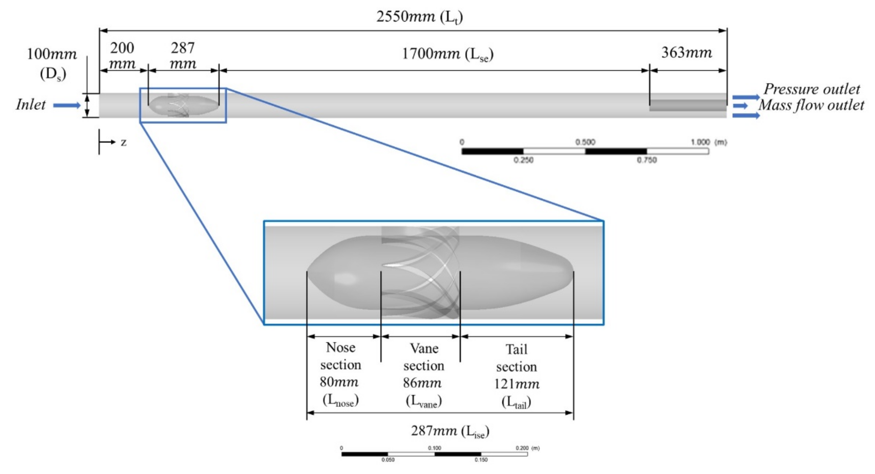
Figure 1 shows a schematic of the in-line oil separator used in this study, referring to Slot’s internal swirl element (ISE) [21]. The total length (Lt) of the oil separator was 2550 mm, and the internal swirl element was installed 200 mm away from the inlet. The outer diameter (Ds) of the internal swirl element was 100 mm, and the total length (Lise) was 287 mm. Additionally, the internal swirl element consisted of nose, vane, and tail sections, and they were 80 mm (Lnose), 86 mm (Lvane), and 121 mm (Ltail), respectively.
In this study, the shapes of the vane were determined using the following NACA 4-digit formula [32]:
Calculate the curve of the mean camber line:
Calculate the gradient of the mean camber line:
Calculate the upper and lower surface:
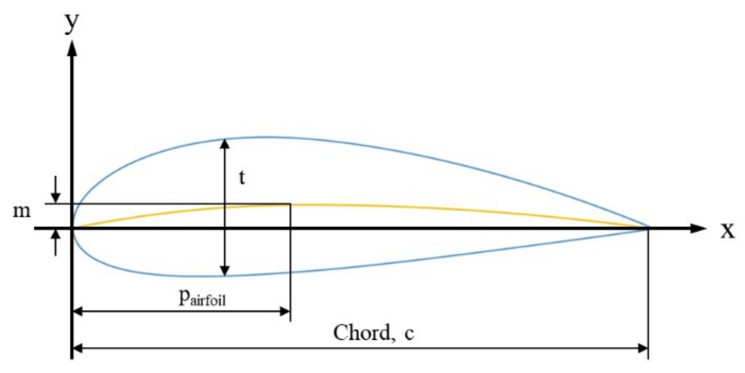
where m is the maximum camber, is the location of the maximum camber, and t is the maximum thickness, respectively (see Figure 2).
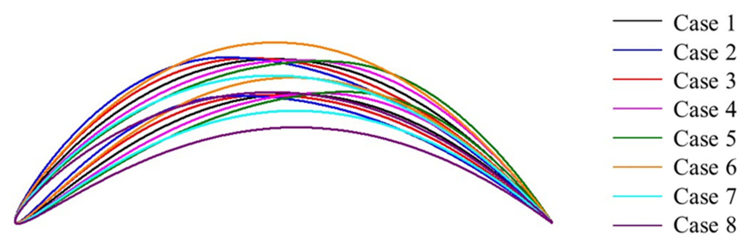
Table 1 describes the configuration of the vane used in the study. The maximum thickness tmax, scaled with the cord length (c), is 4.8%. Figure 3 shows the shapes of the vane used in the study.
The oil separator has one inlet and two exits for oil and water discharge. Velocity inflow, mass flow rate outlet, and pressure outlet were established as the numerical boundary conditions. For water, the volume fraction flowing into the separator was set to 0.75; for oil, it was set at 0.25. All walls were set up with a no-slip boundary condition. The physical parameters of the mixtures used in this study and the boundary conditions for numerical calculations are listed in Table 2. The droplet size of the oil, defined as the dispersed phase, was set to 100 μm. The Schiller–Naumann model [33] was used to calculate the drag law in the momentum conservation equation. The governing equations used for numerical calculation are the continuity equation and the momentum equation, and these equations are coupled by the interfacial momentum transfer term M. For each phase k, the equations for conservation of mass and momentum can be written as follows:
where is the volume fraction of phase k. The viscous stress tensor can be written as follows:
is the interfacial momentum transfer. Here, the surface tension effects are neglected, and, therefore, , where the subscripts and indicate water and oil, respectively. For the water phase, the expression for can be written as follows:
where is the drag coefficient and is the diameter of the oil droplets. The correlation of Schiller and Naumann is defined by
where is defined by
However, Equation (10) does not take into account the effect of impeding movement between droplets. The turbulence model used for calculation was applied to the SSG RSM (Speziale-Sarkar-Gatski Reynolds stress model) [34], which is known to be suitable for swirl flow calculations. The Reynolds stress transport equation for incompressible and isothermal flow is given by
where the constant is 0.22, and is turbulence kinetic energy, respectively. is the production term that gives the Reynolds stresses generated by the mean flow velocity gradients. is the pressure strain correlation term. It describes the energy redistribution among the Reynolds stresses, the interaction of the mean velocity gradient field, the fluctuating velocity field, and the return to the isotropy mechanism of the Reynolds stresses due to energy redistribution. Although pressure strain correlation expressions are extremely complex non-linear equations, these equations provide increased accuracy. However, it also leads to numerical instability during iterative calculations. The pressure strain correlation term of the SSG RSM is given by
where is the normalized anisotropy tensor, defined by
is the production of turbulent kinetic energy, defined by
Furthermore, is the mean strain rate tensor, defined by
and is the mean vorticity tensor, defined by
The constants of the pressure strain correlation term in the SSG RSM are given in Table 3. The turbulence model equation, SSG RSM, was calculated using the commercial code ANSYS CFX 2020R1.
2.2. Grid Systems and Validation
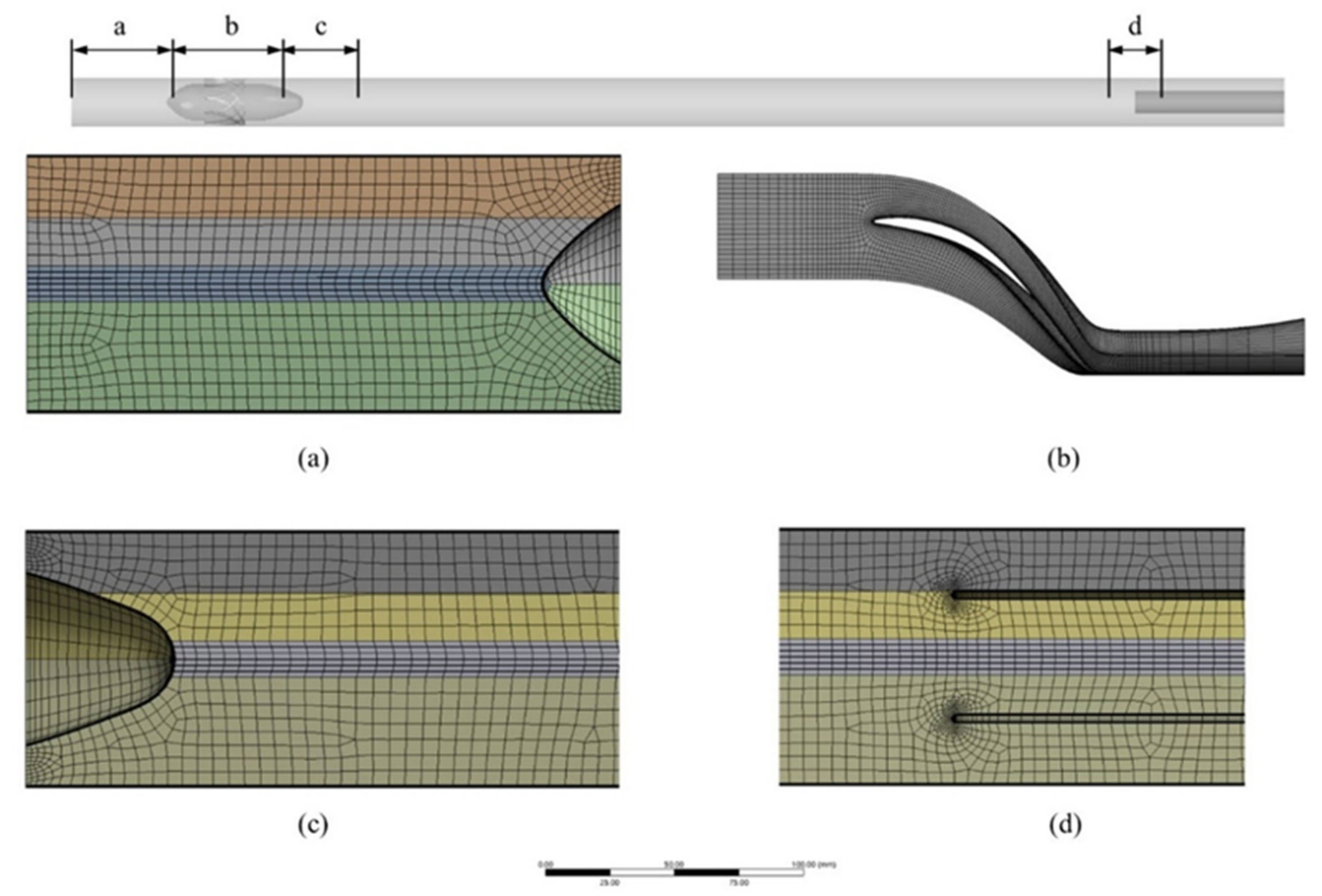
Figure 4 and Table 4 show the grid system of the oil separator; the grid system was composed of triangular prism and hexahedron using ANSYS meshing and turbo grid. The vane was axisymmetric, and a hexahedron grid was constructed using the turbo grid in Figure 4b. The inflation layer was composed of a triangular prism grid, and a scalable wall function was used. In order to minimize the effect of the grid size on the numerical calculation results, a grid dependency test was performed using the results of the separation efficiency. The separation efficiency is defined as the ratio of the oil mass flow rate through the inner outlet to the oil mass flow rate at the inlet. The separation efficiency () can be calculated by the following equation:
The number of grid elements was calculated by changing from 70,000 to 250,000, and, as a result, the change in separation efficiency was insignificant from about 208,000 (see Figure 5). Figure 6 shows the comparison of the numerical analysis results and experimental values of Slot et al. [21] with the calculation results of the present study.
3. Results and Discussion
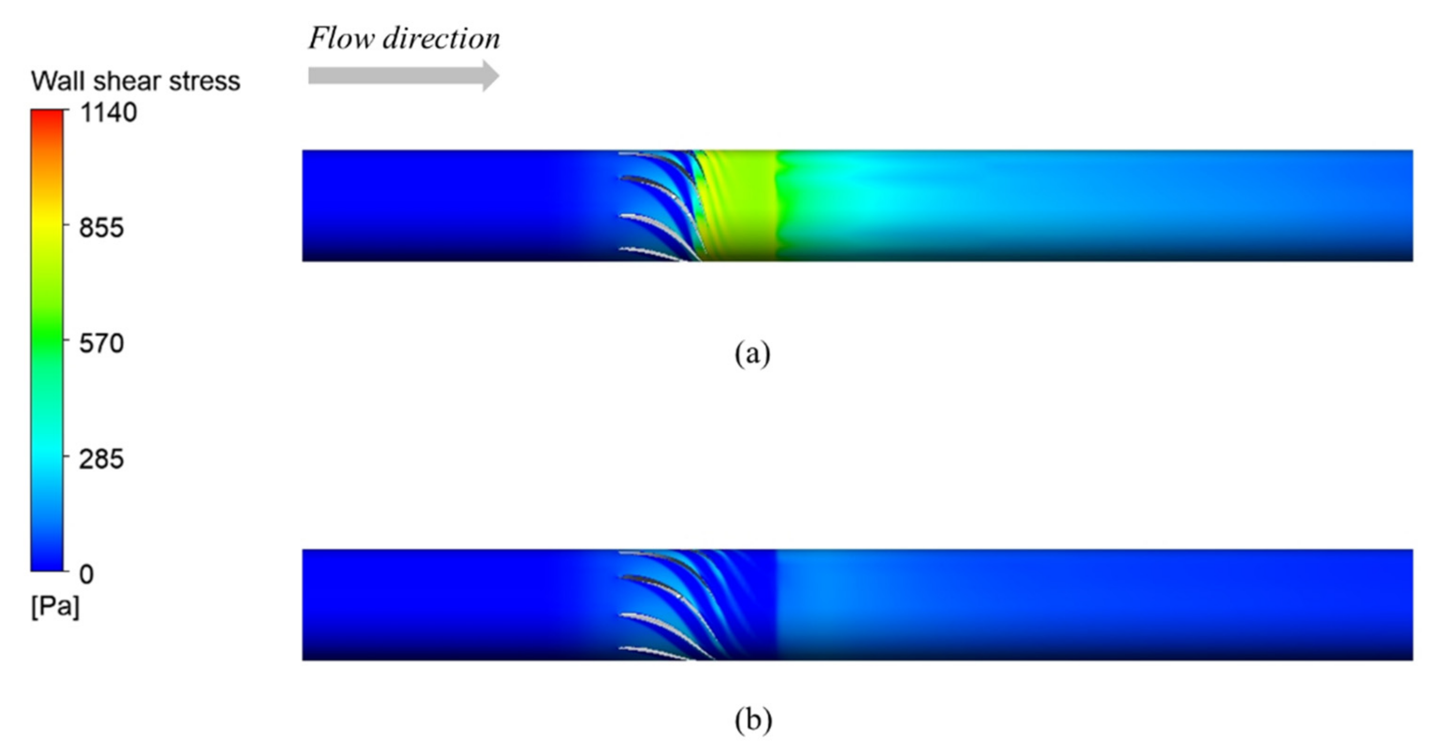
The working fluid passing through the ISE forms a strong swirl flow. Figure 7a shows the axial water velocity at a distance of 4Ds from the ISE, and Figure 7b shows the tangential water velocity for each case. A W-shaped axial water velocity distribution, with relatively slow axial water velocity between the pipe wall and the pipe center, is formed; this W-shaped velocity distribution has been observed by Mattner et al. [35]. The axial water velocity near the pipe wall was faster than the pipe center, and the axial water velocity at the pipe center increased downstream. It was calculated that the smaller the maximum camber value, the slower the tangential water velocity. As the maximum camber value decreases, the vane angle (see Figure 8) decreases, which is considered to decrease the tangential water velocity. Additionally, as the location of the maximum camber of the vane is closer to the inlet, the tangential water velocity tends to increase. The maximum tangential velocity is divided into the forced vortex and the free vortex, which is similar to the Rankine vortex structure [36]. The tangential velocity in the forced vortex region was proportionate to the radius, while the tangential velocity in the free vortex region decreased. In addition, due to wall friction, the tangential velocity rapidly decreased near the wall. Figure 9 shows the distribution of wall shear stress for Case 6 and Case 8. The larger the maximum camber and the closer the location of the maximum camber to the inlet, the greater the wall shear stress.
Figure 10 shows the pressure distribution in the cross-section(A-A’) at a distance of 4Ds from the ISE. The pressure was increased from the center to the wall of the pipe, and the tangential water velocity was higher near the wall. In Case 6, where the maximum tangential water velocity was relatively fast and the minimum axial water velocity was slow, the pressure was high near the wall, and a relatively low-pressure distribution area was wide in the center of the pipe. Figure 11 shows the results of calculating the pressure difference using the averaged pressure values in the cross-sectional planes upstream and downstream of the ISE. As a result, it could be noted that the larger the pressure difference, the larger the maximum magnitude of the axial water velocity.
Table 5 shows the separation efficiency calculation results. As a result of calculating the separation efficiency by changing the location of the maximum camber value from 40% to 60%, it was calculated that the separation efficiency was relatively high at the location of maximum camber 50%. Results also show that the separation efficiency was calculated to be relatively high in Case 9 (at maximum camber 13.51), which had the lowest maximum camber value. In the case where the maximum camber value is larger, the vane angle becomes large. As a result, the axial water velocity was slowed, and the tangential water velocity was increased downstream of ISE. It was calculated that as the maximum camber value was increased, the tangential water velocity increased, and a strong swirl flow was formed. However, the separation efficiency was calculated to be increased in the case where a relatively weak swirl flow was formed.
4. Conclusions
In this study, a numerical analysis was performed on the separation characteristics of an in-line type oil–water separator according to various vane airfoil configurations. In particular, numerical analysis was conducted using the maximum camber value and the location of the maximum camber of the ISE. When the maximum camber value was 13.51%, it was calculated as the highest separation efficiency of 63.9%, and when the location of the maximum camber was 50%, it was confirmed that oil–water separation was performed relatively well. In other words, when the angle of the vane is relatively large, it is considered that the separation is not effectively achieved downstream of ISE due to the formation of a strong swirling flow. In addition, it was confirmed that the pressure difference between the front and rear of the ISE was relatively large due to a strong swirling flow.
In a future study, the optimal design of the airfoil and piping of the in-line oil separator will be conducted, and a separation performance prediction model using AI (artificial intelligence) technology will be studied for various boundary conditions and configurations.
Author Contributions
Conceptualization, Y.-W.J., J.-C.L., and Y.-J.K.; methodology, Y.-W.J.; software, Y.-W.J.; validation, Y.-W.J.; formal analysis, Y.-W.J., and J.-C.L.; investigation, Y.-W.J.; resources, Y.-W.J.; data curation, Y.-W.J., and J.-C.L.; writing—original draft preparation, Y.-W.J.; writing—review and editing, Y.-W.J., and Y.-J.K.; supervision, Y.-J.K. All authors have read and agreed to the published version of the manuscript.
Funding
This research is supported by the Korea Agency for Infrastructure Technology Advancement (KAIA) grant funded by the Ministry of Land, Infrastructure, and Transport (Grant RS-2022-00142936).
Institutional Review Board Statement
Not applicable.
Informed Consent Statement
Not applicable.
Data Availability Statement
The data presented in this study are available on request from the corresponding author.
Conflicts of Interest
The authors declare no conflict of interest.
Nomenclature
| Symbols | Description |
| Volume faction | |
| Dynamic viscosity | |
| Density | |
| Viscous stress tensor | |
| Separation efficiency | |
| Drag coefficient | |
| Droplet diameter | |
| Interfacial momentum transfer of oil | |
| Interfacial momentum transfer of water | |
| Static pressure | |
| Location of maximum camber | |
| Q | Mass flow rate |
| Reynold number | |
| M | Maximum camber |
| t | Thickness of airfoil |
| Instantaneous velocity | |
| Mean velocity | |
| Turbulent velocity fluctuations |
References
- Wang, B.; Xu, D.; Chu, K.; Yu, A. Numerical study of gas–solid flow in a cyclone separator. Appl. Math. Model. 2006, 30, 1326–1342. [Google Scholar] [CrossRef] [Green Version]
- Zhou, H.; Hu, Z.; Zhang, Q.; Wang, Q.; Lv, X. Numerical study on gas-solid flow characteristics of ultra-light particles in a cyclone separator. Powder Technol. 2019, 344, 784–796. [Google Scholar] [CrossRef]
- Chu, K.W.; Wang, B.; Xu, D.L.; Chen, Y.X.; Yu, A.B. CFD-DEM simulation of the gas-solid flow in a cyclone separator. Chem. Eng. Sci. 2011, 66, 834–847. [Google Scholar] [CrossRef]
- Mikulčić, H.; Vujanović, M.; Ashhab, M.S.; Duić, N. Large eddy simulation of a two-phase reacting swirl flow inside a cement cyclone. Energy 2014, 75, 89–96. [Google Scholar] [CrossRef]
- Klujszo, L.A.; Rafaelof, M.; Rajamani, R.K. Dust collection performance of a swirl air cleaner. Powder Technol. 1999, 103, 130–138. [Google Scholar] [CrossRef]
- Hoekstra, A.J. Gas Flow Field and Collection Efficiency of Cyclone Separators. Ph.D. Thesis, Delft University of Technology, Delft, The Netherlands, 2000. [Google Scholar]
- Swanborn, R.A. A New Approach to the Design of Gas-Liquid Separators for the Oil Industry. Ph.D. Thesis, Delft University of Technology, Delft, The Netherlands, 1988. [Google Scholar]
- Liu, W.; Bai, B. Swirl decay in the gas–liquid two-phase swirling flow inside a circular straight pipe. Exp. Therm. Fluid Sci. 2015, 68, 187–195. [Google Scholar] [CrossRef]
- Yue, T.; Chen, J.; Song, J.; Chen, X.; Wang, Y.; Jia, Z.; Xu, R. Experimental and numerical study of Upper Swirling Liquid Film (USLF) among Gas-Liquid Cylindrical Cyclones (GLCC). Chem. Eng. J. 2019, 358, 806–820. [Google Scholar] [CrossRef]
- Rocha, A.D.; Bannwart, A.C.; Ganzarolli, M.M. Numerical and experimental study of an axially induced swirling pipe flow. Int. J. Heat Fluid Flow 2015, 53, 81–90. [Google Scholar] [CrossRef]
- Huang, L.; Deng, S.; Chen, Z.; Guan, J.; Chen, M. Numerical analysis of a novel gas-liquid pre-separation cyclone. Sep. Purif. Technol. 2018, 194, 470–479. [Google Scholar] [CrossRef]
- Wang, G.; Yan, C.; Fan, G.; Wang, J.; Xu, J.; Zeng, X.; Liu, A. Experimental study on a swirl-vane separator for gas–liquid separation. Chem. Eng. Res. Des. 2019, 151, 108–119. [Google Scholar] [CrossRef]
- Xiong, Z.; Lu, M.; Wang, M.; Gu, H.; Cheng, X. Study on flow pattern and separation performance of air–water swirl-vane separator. Ann. Nucl. Energy 2014, 63, 138–145. [Google Scholar] [CrossRef]
- Hreiz, R.; Gentric, C.; Midoux, N.; Lainé, R.; Fünfschilling, D. Hydrodynamics and velocity measurements in gas–liquid swirling flows in cylindrical cyclones. Chem. Eng. Res. Des. 2014, 92, 2231–2246. [Google Scholar] [CrossRef]
- Liu, L.; Wang, K.; Bai, B. Experimental study on flow patterns and transition criteria for vertical swirling gas-liquid flow. Int. J. Multiph. Flow 2020, 122, 103113. [Google Scholar] [CrossRef]
- Delfos, R.; Murphy, S.; Stanbridge, D.; Olujic, D.; Jansens, P.J. A design tool for optimising axial liquid–liquid hydrocyclones. Miner. Eng. 2004, 17, 721–731. [Google Scholar] [CrossRef]
- Amini, S.; Mowla, D.; Golkar, M. Developing a new approach for evaluating a de-oiling hydrocyclone efficiency. Desalination 2012, 285, 131–137. [Google Scholar] [CrossRef]
- Huang, S. Numerical Simulation of Oil-water Hydrocyclone Using Reynolds-Stress Model for Eulerian Multiphase Flows. Can. J. Chem. Eng. 2008, 83, 829–834. [Google Scholar] [CrossRef]
- Lu, Y.; Zhou, L.; Shen, X. Numerical simulation of strongly swirling turbulent flows in a liquid-liquid hydrocyclone using the Reynolds stress transport equation model. Sci. China 2000, 43, 86–96. [Google Scholar] [CrossRef]
- Campen, L.V.; Mudde, R.F.; Slot, J.J.; Hoeihmakers, H. A numerical and experimental survey of a liquid-liquid axial cyclone. Int. J. Chem. React. Eng. 2012, 10, A35. [Google Scholar] [CrossRef]
- Slot, J.J.; Campen, L.V.; Hoeijmakers, H.; Mudde, R.F. In-line oil-water separation in swirling flow. In Proceedings of the 8th International Conference on CFD in Oil & Gas, Metallurgical and Process Industries, Trondheim, Norway, 21–23 June 2011. [Google Scholar]
- Oropeza-Vazquez, C.; Afanador, E.; Gomez, L.; Wang, S.; Mohan, R.; Shoham, O.; Kouba, G. Oil-water separation in a novel liquid-liquid cylindrical cyclone (LLCC) compact separator-Experiments and modeling. In Proceeding of ASME FEDSM’03, Honolulu, HI, USA, 6–10 July 2003. FEDSM2003-45547. [Google Scholar]
- Zeng, X.; Zhao, L.; Fan, G.; Yan, C. Numerical and experimental study on a new axial separator for liquid-liquid separation. J. Taiwan Inst. Chem. Eng. 2021, 123, 104–114. [Google Scholar] [CrossRef]
- Husveg, T.; Rambeau, O.; Drengstig, T.; Bilstad, T. Performance of a deoiling hydrocyclone during variable flow rates. Miner. Eng. 2007, 20, 368–379. [Google Scholar] [CrossRef]
- Sharifi, K.; Behnahani, T.J.; Ebrahimi, S.; Sabeti, M.; Soflaee, S. A new computational fluid dynamics study of a liquid-liquid hydrocyclone in the two phase case for separation of oil droplets and water. Braz. J. Chem. Eng. 2019, 36, 1601–1612. [Google Scholar] [CrossRef] [Green Version]
- Noroozi, S.; Hashemabadi, S.H. CFD Simulation of Inlet Design Effect on Deoiling Hydrocyclone Separation Efficiency. Chem. Eng. Technol. 2009, 32, 1885–1893. [Google Scholar] [CrossRef]
- Zeng, X.; Zhao, L.; Zhao, W.; Hou, M.; Zhu, F.; Fan, G.; Yan, C. Experimental study on a compact axial separator with conical tube for liquid-liquid separation. Sep. Purif. Technol. 2021, 257, 117904. [Google Scholar] [CrossRef]
- Schütz, S.; Gorbach, G.; Piesche, M. Modeling fluid behavior and droplet interactions during liquid–liquid separation in hydrocyclones. Chem. Eng. Sci. 2009, 64, 3935–3952. [Google Scholar] [CrossRef]
- Young, G.; Wakley, W.; Taggart, D.; Andrews, S.; Worrell, J. Oil-water separation using hydrocyclones: An experimental search for optimum dimensions. J. Pet. Sci. Eng. 1994, 11, 37–50. [Google Scholar] [CrossRef]
- Al-Kayiem, H.H.; Hamza, J.E.; Lemmu, T.A. Performance enhancement of axial concurrent liquid–liquid hydrocyclone separator through optimization of the swirler vane angle. J. Pet. Explor. Prod. Technol. 2020, 10, 2957–2967. [Google Scholar] [CrossRef]
- Zeng, X.; Xu, Y.; Zhao, L.; Fan, G.; Yan, C. Numerical investigation on axial liquid-liquid separators with different swirl chambers. Chem. Eng. Processing Process Intensif. 2021, 161, 108324. [Google Scholar] [CrossRef]
- Jacobs, E.N.; Ward, K.E.; Pinkerton, R.M. The characteristics of 78 Related Airfoil Sections from Tests in the Variable-Density Wind Tunnel; Technical Report; NACA: Hampton, VA, USA, 1933. [Google Scholar]
- Shiller, L.; Naumann, A. A drag coefficient correlation. Z. Des Ver. Dtsch. Ing. 1935, 77, 318–320. [Google Scholar]
- Speziale, C.G.; Sarkar, S.; Gatski, T.B. Modelling the pressure-strain correlation of turbulence: An invariant dynamical systems approach. J. Fluid Mech. 1991, 227, 245–272. [Google Scholar] [CrossRef]
- Mattner, T.W.; Joubert, P.N.; Chong, M.S. Vortical flow. part 1. flow through a constant-diameter pipe. J. Fluid Mech. 2002, 463, 259–291. [Google Scholar] [CrossRef] [Green Version]
- Rankine, W.J.M. A Manual of Applied Mechanics; Charles Griffin and Co.: London, UK, 1877. [Google Scholar]
Figure 1.
Schematic of the modeled in-line oil separator.

Figure 2.
Parameters of the NACA 4-digit airfoil.

Figure 3.
Various NACA airfoil models applied in this study.

Figure 4.
Grid systems: (a) stage a, (b) stage b, (c) stage c, (d) stage d.

Figure 5.
Grid dependency test.

Figure 6.
Comparison of the present study and literature data of numerical and experimental results [21].
Figure 6.
Comparison of the present study and literature data of numerical and experimental results [21].

Figure 7.
CFD (Computational fluid dynamics) results at 4Ds downstream of the ISE: (a) axial water velocity, (b) tangential water velocity.
Figure 7.
CFD (Computational fluid dynamics) results at 4Ds downstream of the ISE: (a) axial water velocity, (b) tangential water velocity.

Figure 8.
Schematic of the modeled vane angle.

Figure 9.
Distribution of wall shear stress: (a) Case 6, (b) Case 8.

Figure 10.
Distribution of pressure at 4 Ds(A-A’) downstream of the ISE: (a) case 1, (b) case 2, (c) case 3, (d) case 4, (e) case 5, (f) case 6, (g) case 7, (h) case8.
Figure 10.
Distribution of pressure at 4 Ds(A-A’) downstream of the ISE: (a) case 1, (b) case 2, (c) case 3, (d) case 4, (e) case 5, (f) case 6, (g) case 7, (h) case8.

Figure 11.
Area-averaged pressure difference between the front and rear of the ISE.


Table 1.
Design parameters of the numerical analysis.
| Maximum Camber (m) [%] | Location of Maximum Camber (p) [%] | |
|---|---|---|
| Case 1 | 17.51 | 50 |
| Case 2 | 17.51 | 40 |
| Case 3 | 17.51 | 45 |
| Case 4 | 17.51 | 55 |
| Case 5 | 17.51 | 60 |
| Case 6 | 19.51 | 50 |
| Case 7 | 15.51 | 50 |
| Case 8 | 13.51 | 50 |
Table 2.
Boundary conditions applied in this study.
| Value | ||||
|---|---|---|---|---|
| Calculation type | Steady state | |||
| Turbulence model | SSG Reynolds stress model [34] | |||
| Working fluid | Water | Density | 1068.7 | |
| Viscosity | 1.183 × 10⁻³ | |||
| Oil | Density | 867 | ||
| Viscosity | 8.69 × 10⁻³ | |||
| Droplet size | 100 | |||
| Gravity (z-axis) | −9.81 | |||
| Inlet | Velocity | 2 | ||
| Volume of fraction | 0.75 0.25 | (water) (oil) | ||
| Outlet | Pressure outlet | 101.325 | ||
| Mass flow outlet | 5.03 | |||
| Wall | No-slip wall | |||
| Drag law | Schiller–Naumann model [33] | |||
Table 3.
Constants of pressure strain correlation term in SSG RSM.
| 1.7 | −1.05 | 0.9 | 0.8 | 0.65 | 0.625 | 0.2 |
Table 4.
Grid systems of the in-line oil separator in this study.
| Stage | Program | Method | No. of Grid |
|---|---|---|---|
| a | ANSYS meshing | Triangular prism, hexahedron | 18,000 |
| b | Turbo grid | Hexahedron | 47,000 |
| c, d | ANSYS meshing | Triangular prism, hexahedron | 143,000 |
Table 5.
Separation efficiency.
| Case | Maximum Camber [%] | Location of Maximum Camber [%] | Separation Efficiency |
|---|---|---|---|
| 1 | 17.51 | 50 | 0.617 |
| 2 | 17.51 | 40 | 0.601 |
| 3 | 17.51 | 45 | 0.606 |
| 4 | 17.51 | 55 | 0.610 |
| 5 | 17.51 | 60 | 0.609 |
| 6 | 19.51 | 50 | 0.595 |
| 7 | 15.51 | 50 | 0.625 |
| 8 | 13.51 | 50 | 0.639 |
Publisher’s Note: MDPI stays neutral with regard to jurisdictional claims in published maps and institutional affiliations. |
© 2022 by the authors. Licensee MDPI, Basel, Switzerland. This article is an open access article distributed under the terms and conditions of the Creative Commons Attribution (CC BY) license (https://creativecommons.org/licenses/by/4.0/).
Share and Cite
MDPI and ACS Style
Je, Y.-W.; Lee, J.-C.; Kim, Y.-J. Performance Characteristics of In-Line Oil Separator with Various Airfoil Vane Configurations of the Axial-Flow Swirl Generator. Processes 2022, 10, 948. https://0-doi-org.brum.beds.ac.uk/10.3390/pr10050948
AMA Style
Je Y-W, Lee J-C, Kim Y-J. Performance Characteristics of In-Line Oil Separator with Various Airfoil Vane Configurations of the Axial-Flow Swirl Generator. Processes. 2022; 10(5):948. https://0-doi-org.brum.beds.ac.uk/10.3390/pr10050948
Chicago/Turabian StyleJe, Yeong-Wan, Jong-Chul Lee, and Youn-Jea Kim. 2022. "Performance Characteristics of In-Line Oil Separator with Various Airfoil Vane Configurations of the Axial-Flow Swirl Generator" Processes 10, no. 5: 948. https://0-doi-org.brum.beds.ac.uk/10.3390/pr10050948
Note that from the first issue of 2016, this journal uses article numbers instead of page numbers. See further details here.