
Research on Wellbore Instability of Shale Formation in Extremely Complex Geo-Mechanical Environment


1
CNOOC Research Institute Co., Ltd., Beijing 100028, China
2
Department of Petroleum Engineering, Xi’an Shiyou University, Xi’an 710065, China
3
Department of Petroleum Engineering, China University of Petroleum (Beijing), Beijing 102249, China
*
Authors to whom correspondence should be addressed.
Processes 2022, 10(6), 1060; https://0-doi-org.brum.beds.ac.uk/10.3390/pr10061060
Submission received: 10 April 2022
/
Revised: 13 May 2022
/
Accepted: 24 May 2022
/
Published: 25 May 2022
(This article belongs to the Special Issue Natural Gas Hydrate Production Technology and Rock Mechanics in Petroleum Engineering)
Abstract
:Borehole instability problems are commonly encountered while drilling highly deviated and horizontal shale gas wells within the shale formations associated with high-dip bedding planes. An integrated rock mechanical study is described in this paper to evaluate the risk of the borehole instability problems in this area. First, a set of uniaxial compressive tests are carried out to measure the strength of the bedding shales on cores with different angles between the load direction and the bedding planes. A critical strength criterion is then proposed based on the test results. Next, the stress state of the borehole with arbitrary inclination and azimuth is determined through coordinate transformations. Finally, through combining the strength criterion and the stress state of the borehole, the risk of borehole instability is investigated for deviated and horizontal wells in shale formations with different bedding dips (0–90°) and dip directions (45° and 90° to the direction of minimum horizontal stress ). The results show the dependence of borehole instability on the orientation of bedding planes of the formation as well as inclination and azimuth of the well. The most desirable borehole trajectory from the viewpoint of borehole stability is at the direction normal to the bedding planes. For a horizontal well specifically, if the bedding direction is perpendicular to the direction of , the risk of instability is relatively high for most drilling directions except drilling along the dip direction of the bedding planes. However, if there is a moderate acute angle (e.g., 45°) between the dip direction and the direction of , the risk of instability is relatively low for most drilling directions unless drilling along the direction of .
1. Introduction
Two key technologies that enable economic development of shale gas are hydraulic fracturing and horizontal drilling [1,2,3,4] (Fisher et al., 2004; Watson et al., 2008; Wiley et al., 2004; Wu, 2015). In the shale gas formations, the pay zones of shale gas are mainly within the marine Paleozoic shale formations. Due to the Himalayan Movement from the late Paleogene to Quaternary, several orogenic belts were formed around the upper Yangtze area, including the Longmen, Qinling, Xuefeng, and Dianqian orogenic belts. Influenced by these orogenic belts, high-dip bedding planes in shale formations have developed substantially in this area. Borehole instability problems continuously occur while drilling highly deviated or horizontal wells in these bedding shales, which further lead to problems of hole enlargements and reaming difficulties. Furthermore, the spalled rock debris due to borehole instability can block the annulus and result in a remarkable pressure buildup in the bottom hole. Lost circulation problems are also experienced as a result of this undesirable pressure buildup. With fluid loss into the formation, the height of the fluid column in the annulus may decrease which causes further borehole instability problems [5,6] (Feng et al., 2016; Feng and Gray, 2016). A vicious circle of borehole instability and lost circulation may continue and eventually lead to very high operational cost and even loss of the entire borehole.
The existing studies on borehole instability in bedding shale formations are mainly focused on characterization of strength anisotropy and investigation of the strength criteria for these formations [7,8,9] (Gao et al., 2014; McLamore and Gray, 1967; Okland and Cook, 1998). However, most of these studies are for conventional drilling in shales with low-dip bedding, usually with dip angles less than 45°, and aim to optimize the drilling trajectory. Unfortunately, they are not suitable for analysis of borehole stability in shales with high-dip bedding planes, e.g., with dip angles larger than 45° or even close to 90°. Currently, there is still a lack of an adequate predictive model for borehole instability of highly deviated and horizontal wells in high-dip bedding shales. Therefore, the objective of this paper is to describe an integrated rock mechanical study for this problem.
2. Rock Mechanical Testing and Strength Criterion for Bedding Shales
2.1. Rock Mechanical Testing
Relatively parallel bedding planes are prevalently developed in the shale formations. Figure 1 shows the bedding planes in an outcrop of the Longmaxi shale formation, which is one of the main gas-bearing formations in this area. From the microscopic perspective, oriented bedding planes are also observed as shown in the SEM image in Figure 2. Figure 3 is a schematic illustration of the dip, dip direction, and normal direction used to describe the orientation of the bedding plane.
Due to the existence of these bedding planes, the shales have a strong anisotropic nature and their mechanical properties can be very different from the relatively isotropic rocks [10] (Yuan, 2012). Furthermore, the strength of the bedding planes is usually lower than that of the shale matrix, therefore these weak planes often fail first while drilling through the shale formations and trigger borehole instability problems. Due to these particular features of bedding shales, it is necessary to carry out rock mechanical testing to identify their strength anisotropy, obtain input data for prediction of borehole instability, and understand the mechanisms of the instability problems [9] (Okland and Cook, 1998). Therefore, a rock mechanical testing investigation was first initiated in this study.
Shale core samples from the Longmaxi formation (where the pore pressure of the reservoir is 32 MPa, and the temperature of the reservoir is 88 °C), with obvious bedding planes, were used for rock mechanical tests. The cores were cut at angle κ from 0° to 90° to the normal direction of the bedding planes (i.e., 0° and 90° mean the axis of the core sample is normal and parallel to the bedding plane, respectively) as shown in Figure 4. A micro coring bit with an inner dimeter of 2.54 cm was used to drill core samples. During the coring process, kerosene was used as the coolant to cool the bit and constant bit weight was used to avoid rupture of the sample. After coring, the two ends of the core samples were cut and sanded flat and parallel to each other. Figure 5 shows some well-processed shale core samples. Uniaxial compressive tests were carried out on each sample. Displacement loading control was utilized during the tests with loading rates of 0.001 mm/s and 0.1 mm/min before and after the failure of the samples, respectively.
The extensive distribution of bedding planes and small natural fractures in the rock constrain the preparation of core samples; as a result, most of the core samples have a length/diameter ratio l/D less than 2.0. The measured uniaxial compressive strength (UCS) is shown with the square points in Figure 6. The results indicate strong dependence of UCS on the loading (axial) directions of the core samples relative to the bedding planes. The UCS with a moderate angle (e.g., 45°) between the loading direction and bedding planes is much smaller than that with a loading direction nearly normal or parallel to the bedding planes, as shown in Figure 6.
It is believed that this measured strength is relatively larger due to the size effect associated with small length/diameter ratio. Therefore, in order to eliminate the error due to size effect [11], the adjustment formula (Equation (1)) was used in this study to adjust the test results of samples with l/D < 2.0 to the standard condition with l/D = 2.0.
where l is the length of the shale core sample, cm; D is the diameter of the shale core sample, cm; σc0 is the measured compressive strength of the core sample, MPa; and σc is the adjusted compressive strength of the core sample, MPa.
2.2. Strength Criterion for Bedding Shales
Due to the anisotropic nature of bedding shales, the strength criteria traditionally used for analyzing failure of relatively isotropic rocks are no longer adequate for evaluation of borehole instability problems in bedding shales. The need for a sufficient strength criterion is therefore paramount [8] (McLamore and Gray, 1967). In this study, the strength criterion for anisotropic rocks with bedding planes proposed by Mclamore and Gray was applied. On the basis of their criterion the strength of the bedding shales in the Longmaxi formation can be evaluated using Equation (2) [12] (E Fjær, 2008), which was obtained by fitting the testing results reported in Table 1 to the strength criterion. Excellent fitting results were obtained as shown in Figure 6.
where σ1, σ3 are the maximum and minimum principal stresses, respectively, MPa; is the internal frictional angle, °; is the cohesive strength which is a function of the angle between the direction of σ1 and the normal direction of the bedding planes, MPa; A1, B1, A2, B2, m, n, and θ’ are fitting parameters. Using the measured strength in Table 1, the fitting parameters were determined as A1 = −17.5 MPa, B1 = −12.5 MPa, A2 = −14 MPa, B2 = −9 MPa, χ = 50°, m = 3, n = 3.
When the cut angle is 45°, the normal stress of the bedding plane is the smallest, and the shear stress is the largest. At this time, slip dislocation is most likely to occur. Therefore, when the angle = 45°, UCS reaches the minimum value.
3. Borehole Stress Analysis
For analyzing borehole instability problems of deviated or horizontal wells, the stress state around the borehole must be determined [13,14] (Frydman and da Fontoura, 2001; Zhang, 2002). When the stress state on the borehole wall goes beyond the failure envelope of the strength criterion (e.g., Equation (2) in this study), borehole instability will occur [10] (Yuan et al., 2012). The threshold drilling mud pressure at the occurrence of borehole instability is usually defined as collapse pressure, and the corresponding drilling mud density is usually called equivalent drilling mud density which is a critical parameter for well design and drilling mud optimization [6,15] (Feng et al., 2016; Li and Gray, 2015).
The stress state around the borehole can be determined through coordinate transformations [12,15,16,17] (Aadnoy, 1987; Fjar et al., 2008; Li and Gray, 2015; Zoback, 2010). A Cartesian coordinate system (X, Y, Z) is first defined according to the directions of the far-field stresses with the X-, Y-, and Z-axis coincident with the directions of maximum horizontal stress , minimum horizontal stress , and the vertical overburden stress , respectively, as shown in Figure 7a. Next, the far-field stresses are transformed to a new Cartesian coordinate (X’, Y’, Z’) with the Z’-axis coincident with the borehole axis and the X’-axis coincident with the azimuth direction of the borehole, as shown in Figure 7b. Finally, the stresses are transformed to a cylindrical coordinate system (r, θ, z) with the z-axis coincident with the borehole axis as shown in Figure 7c. After these coordinate transformations, the stress around the borehole can be determined. In the following sections, coordinate systems (X, Y, Z), (X’, Y’, Z’), and (r, θ, z) are referred to as the field Cartesian coordinate system, borehole Cartesian coordinate system, and borehole cylindrical coordinate system, respectively.
Before a borehole is drilled, the rock is at an initial equilibrium state under the far-field stresses. The initial stress state in the borehole Cartesian coordinate system (X’, Y’, Z’) can be determined as [12,17] (Fjar et al., 2008; Zoback, 2010):
where σ is the stress matrix in the borehole Cartesian coordinate system (X’, Y’, Z’); S is the far-field stress matrix in the field Cartesian coordinate system (X, Y, Z); , , and are the maximum horizontal stress, the minimum horizontal stress, and the vertical overburden stress, respectively, MPa;, , , , , , , , and are the field stress components in the borehole Cartesian coordinate system, MPa; L is the coordinate transformation matrix from the field Cartesian coordinate system (X, Y, Z) to the borehole Cartesian coordinate system (X’, Y’, Z’); LT is the transpose of L; α and β are the inclination and azimuth of the borehole, respectively, °.
After a borehole is drilled, it is more convenient to analyze the stress state around and the failure of the borehole using the borehole cylindrical coordinate system (r, θ, z). The stress state on the borehole wall can be obtained by superposing the stresses induced by the field stress components in Equation (4) and drilling mud pressure Pw in the borehole. It can be expressed as [18,19,20]:
where σr, σθ, σz are the radial, tangential, and axial stresses on the borehole wall in the cylindrical coordinate system (r, θ, z), MPa; σrθ, σθz, σzr are the shear stress components in the cylindrical coordinate system, MPa; Pw is borehole pressure, MPa; Pp is pore pressure in the formation, MPa; is a nonlinear correction coefficient, dimensionless; is the porosity of the rock, dimensionless; is the circumferential angle of the wellbore, °; is the effective stress coefficient, dimensionless; is Poisson’s ratio, dimensionless.
Equation (7) implies that, at the borehole wall, σr is a principal stress, but σθ and σz are not because the shear stress on the θ-z plane is not zero. Through stress analysis, the normal stress and shear stress on an oblique plane at angle γ to the z-axis can be obtained as:
The other two principal stresses on the borehole wall can be determined by taking the derivative of shear stress (Equation (9)) with respect to γ and setting it equal to zero. The angles γ for the other two mutually orthogonal principal stresses are therefore determined as [21]:
Substituting Equation (10) into Equation (8), the other two principal stresses on the borehole wall are obtained as:
After the determination of the three principal stresses, the collapse pressure for highly deviated and horizontal boreholes in bedding shale formations can be determined using the strength criterion presented in Section 2. In the following section, a case study is performed to investigate the risk of instability of deviated and horizontal boreholes with various dip angles and dip directions of the bedding planes and with different inclinations and azimuths of boreholes [22,23,24].
4. Case Study
As aforementioned, borehole instability problems of deviated and horizontal wells in shale formations with high-dip bedding planes are not fully understood and require further elucidation [25,26]. Therefore, a case study is presented in this section to illustrate this problem.
A bedding shale formation with a depth of 2200 m is considered in this study. The internal friction angle of this shale formation is determined to be 33°. The cohesive strength τ0(κ) is a function of bedding dip and given by Equation (3) in Section 2. The internal friction angle and cohesive strength should be determined through rock mechanical testing for each individual shale formation with different bedding planes. The maximum horizontal stress , minimum horizontal stress , and overburden stress of this formation are 52 MPa, 46 MPa, and 42 MPa, respectively. The direction of the minimum horizontal stress is at N60° E. In compressive tectonic regimes, the dip direction of the bedding planes is usually at an angle less than or equal to 90° to the direction of the minimum horizontal stress. In this case study, two cases with bedding dip directions of N150° E and N15° E (i.e., 90° and 45° to the direction of minimum horizontal stress) are considered.
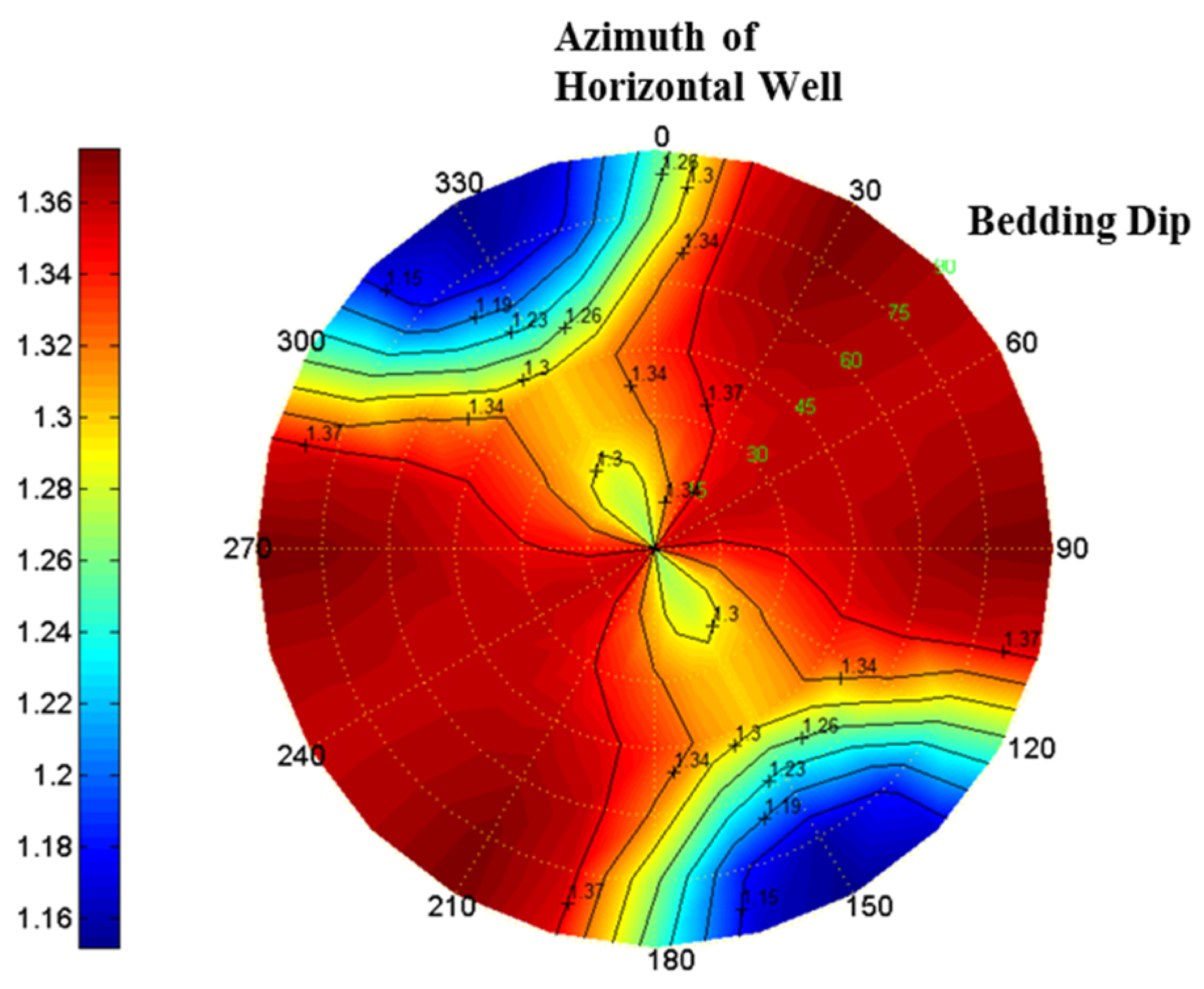
For the case of a shale formation with bedding dip direction of N150° E (perpendicular to the direction of minimum horizontal stress), collapse pressures of boreholes with arbitrary inclination and azimuth and different bedding dips are calculated and plotted in Figure 8. Different plots show the results with different dip angles (0°, 20°, 30°, 50°, 70°, and 90°, respectively) of the bedding planes. For each plot, the azimuth of the borehole is shown in the circumferential direction of the plot from 0° to 360°, with 0° and 180° corresponding to north and south, respectively. Therefore, the direction of the minimum horizontal stress and the dip direction of the bedding planes are at 60° and 150° on the plots, respectively. The radial distance from the center to the outer boundary of the plots represents the inclinations of the borehole from 0° (vertical borehole) to 90° (horizontal borehole). In these plots, red means relatively high collapse pressure and hence high risk of borehole instability in the corresponding conditions, while blue means relatively low risk of instability [27,28].
Figure 8 indicates that, with the increase in the dip angle of the bedding planes, the safe (blue) region of the well trajectory changes and remains relatively small. This means the risk of borehole instability is high for most drilling trajectories when the dip direction of the bedding planes is perpendicular to the direction of minimum horizontal stress. Furthermore, through a close examination of the plots in Figure 8, it is found that well trajectories in the blue region are always approximately normal to the bedding planes. Therefore, it can be concluded that, from the viewpoint of borehole stability, the most desirable drilling direction in bedding shale formations is normal to the bedding planes.
For horizontal boreholes particularly, with the same bedding dip direction of N150° E, Figure 9 shows their collapse pressure for different azimuths of the borehole and dip angles of the bedding planes. It can be seen that the collapse pressure for most regions is relatively high, indicating a high risk of borehole instability for drilling horizontal wells in this bedding shale formation. When drilling perpendicularly to the dip direction of the bedding planes, collapse pressure and thus risk of borehole instability are relatively high and increase with the increase in the dip angle of the bedding planes. However, for a borehole parallel to the dip direction of the bedding planes, the collapse pressure is relatively small, especially for formations with high dip angles. Therefore, the most optimal drilling direction of a horizontal well for avoiding borehole instability problems is drilling along the dip direction of the bedding planes.
Similarly, collapse pressures of a shale formation with a bedding dip direction of N15° E (45° to the direction of minimum horizontal stress) for different borehole inclinations, borehole azimuths, and bedding dip angles are also calculated and plotted in Figure 10. The safe (blue) region moves with the change in dip angle. However, this safe region remains much larger than that in the above case. This means the risk of borehole instability is relatively low for most drilling trajectories when the dip direction of the bedding planes is at a moderate acute angle to the direction of the minimum horizontal stress. From the viewpoint of borehole stability, the most desirable borehole trajectory in this case is also at the direction normal to the bedding planes.
With the same bedding dip direction of N15° E, Figure 11 shows the collapse pressure of a horizontal borehole with different azimuths of the borehole and dip angles of the bedding planes. The collapse pressure for most regions is relatively low, implying a relatively low risk of borehole instability. High risk of instability only exists while drilling at the direction of the minimum horizontal stress. As in the above case, the most optimal direction for drilling horizontal wells is also along the dip direction of the bedding planes.
5. Conclusions
Bedding planes in shale formations are recognized as a key factor causing borehole instability problems. In this paper, a rock mechanical study integrating rock strength testing and mathematical modeling to understand and resolve the borehole instability problems is described.
Uniaxial compressive strength of bedding shale samples from the Longmaxi formation was measured with different angles between the principal stress and the bedding planes. The results display higher rock strength when the principal stress is normal or parallel to the bedding planes and relatively lower strength with moderate angles between the principal stress and the bedding planes. Based on the testing results, a specific strength criterion was proposed for the Longmaxi bedding shale formation. Through combining the stress state around the borehole and the proposed strength criterion, the risk of borehole instability was investigated for deviated and horizontal wells in bedding shales with different dips and dip directions.
When the dip direction of the bedding plane is perpendicular to the direction of the minimum horizontal stress, the risk of borehole instability is relatively high for most drilling trajectories, while, with a moderate acute angle between them, the risk of instability is relatively low for most drilling trajectories and high risk only exists when drilling along the direction of minimum horizontal stress. For both cases, the most desirable borehole trajectory is drilling normal to the bedding planes. Therefore, it is recommended to drill wells as close to the normal direction of the bedding planes as possible to avoid borehole instability problems, and successful implementations have been achieved.
Author Contributions
Conceptualization, J.Y.; methodology, J.Y.; software, Y.F.; validation, J.Y. and K.Z.; formal analysis, J.Y. and Y.F.; investigation, J.Y.; resources, J.Y.; data curation, K.Z.; writing—original draft preparation, J.Y.; writing—review and editing, Y.F.; visualization, K.Z.; supervision, J.Y.; project administration, J.Y.; funding acquisition, Y.F. and J.Y. All authors have read and agreed to the published version of the manuscript.
Funding
This research was funded by [The Basic Research Project of State Key Laboratory of Natural Gas Hydrate] grant number [2022-KJYFPT-SHW], [The Research Project of CNOOC Co., Ltd.] grant number [YXKY-ZX-09-2021], [The Science Foundation of China University of Petroleum, Beijing] grant number [2462019YJRC008], [National Natural Science Foundation of China] grant number [52074312] And The APC was funded by [52074312].
Institutional Review Board Statement
Not applicable.
Informed Consent Statement
Not applicable.
Data Availability Statement
Not applicable.
Conflicts of Interest
The authors declare no conflict of interest.
Nomenclature
| A1 | fitting parameter, MPa |
| A2 | fitting parameter, MPa |
| B1 | fitting parameter, MPa |
| B2 | fitting parameter, MPa |
| D | diameter of shale core sample, cm |
| L | coordinate transformation matrix from the field Cartesian coordinate system to the borehole Cartesian coordinate system |
| LT | the transpose of L |
| l | length of shale core sample, cm |
| m | fitting parameter, dimensionless |
| n | fitting parameter, dimensionless |
| Pp | pore pressure in the formation, MPa |
| Pw | borehole pressure, MPa |
| α | inclination of borehole, ° |
| effective stress coefficient, dimensionless | |
| β | azimuth of borehole, ° |
| γ | angel between an oblique plane and z-axis of the wellbore cylindrical coordinate system, ° |
| nonlinear correction coefficient, dimensionless | |
| circumferential angle of the wellbore from the direction of the maximum horizontal stress, ° | |
| fitting parameters, ° | |
| κ | angle between core axis and normal direction of bedding planes, ° |
| Poisson’s ratio, dimensionless | |
| normal stress at an oblique plane at angle γ to z-axis of the wellbore cylindrical coordinate system, MPa | |
| σ1 | maximum principal stresses, MPa |
| σ3 | minimum principal stresses, MPa |
| σc | adjusted compressive strength of core sample, Mpa |
| σc0 | measured compressive strength of core sample, Mpa |
| maximum horizontal stress, Mpa | |
| minimum horizontal stress, Mpa | |
| overburden stress, Mpa | |
| field stress components in the borehole Cartesian coordinate system, Mpa | |
| σr, σθ, σz | radial, tangential, and axial stresses on borehole wall in the wellbore cylindrical coordinate system, MPa |
| σrθ, σθz, σzr | shear stress components in the wellbore cylindrical coordinate system, MPa |
| two principal stresses on the wellbore wall, MPa | |
| shear stress at an oblique plane at angle γ to z-axis of the wellbore cylindrical coordinate system, MPa | |
| τ0(κ) | cohesive strength, MPa |
| internal frictional angle, ° | |
| porosity, dimensionless | |
| χ | fitting parameters, ° |
References
- Fisher, M.K.; Heinze, J.R.; Harris, C.D.; Davidson, B.M.; Wright, C.A.; Dunn, K.P. Optimizing Horizontal Completion Techniques in the Barnett Shale Using Microseismic Fracture Mapping. In Proceedings of the SPE Annual Technical Conference and Exhibition, Houston, TX, USA, 26–29 September 2004. [Google Scholar]
- Watson, D.R.; Durst, D.G.; Harris, J.T.; Contreras, J.D. One-Trip Multistage Completion Technology for Unconventional Gas Formations. In Proceedings of the CIPC/SPE Gas Technology Symposium 2008 Joint Conference, Calgary, AB, Canada, 16–19 June 2008. [Google Scholar]
- Wiley, C.; Barree, B.; Eberhard, M.; Lantz, T. Improved Horizontal Well Stimulations in the Bakken Formation, Williston Basin, Montana. In Proceedings of the SPE Annual Technical Conference and Exhibition, Houston, TX, USA, 26–29 September 2004. [Google Scholar]
- Wu, K. Numerical Modeling of Complex Hydraulic Fracture Development in Unconventional Reservoirs. Ph.D. Thesis, The University of Texas at Austin, Austin, TX, USA, 2015. [Google Scholar]
- Feng, Y.; Gray, K.E. A parametric study for wellbore strengthening. J. Nat. Gas Sci. Eng. 2016, 30, 350–363. [Google Scholar] [CrossRef]
- Feng, Y.; Jones, J.F.; Gray, K.E. A Review on Fracture-Initiation and -Propagation Pressures for Lost Circulation and Wellbore Strengthening. SPE Drill. Complet. 2016, 31, 134–144. [Google Scholar] [CrossRef]
- Gao, H.J.; Odunlami, T.; Osayande, N. Shale Bedding Impact on Wellbore Stability and Drilling Optimization. In Proceedings of the SPE/CSUR Unconventional Resources Conference—Canada, Calgary, AB, Canada, 30 September–2 October 2014. [Google Scholar]
- McLamore, R.T.; Gray, K.E. A Strength Criterion for Anisotropic Rocks Based Upon Experimental Observations. In Proceedings of the Annual Meeting of the American Institute of Mining, Metallurgical, and Petroleum Engineers, Los Angeles, CA, USA, 19–23 February 1967. [Google Scholar]
- Okland, D.; Cook, J.M. Bedding-Related Borehole Instability in High-Angle Wells. In Proceedings of the SPE/ISRM Rock Mechanics in Petroleum Engineering, Trondheim, Norway, 8–10 July 1998. [Google Scholar]
- Yuan, J.-L.; Deng, J.-G.; Tan, Q.; Yu, B.-H.; Jin, X.-C. Borehole Stability Analysis of Horizontal Drilling in Shale Gas Reservoirs. Rock Mech. Rock Eng. 2012, 46, 1157–1164. [Google Scholar] [CrossRef]
- Yuan, J.; Deng, J.; Li, D.; Cheng, L.; Yan, W.; Hu, L.; Lin, H. Calculation of Micro-hole Collapse Pressure in Gas Shale. Sci. Technol. Rev. 2013, 31, 71–74. [Google Scholar]
- Fjar, E.; Holt, R.M.; Horsrud, P.; Raaen, A.M. Petroleum Related Rock Mechanics, 2nd ed.; Elsevier: Amsterdam, The Netherlands, 2008. [Google Scholar]
- Frydman, M.; da Fontoura, S.A.B. Modeling Aspects of Wellbore Stability in Shales. In Proceedings of the SPE Latin American and Caribbean Petroleum Engineering Conference, Buenos Aires, Argentina, 25–28 March 2001. [Google Scholar]
- Zhang, J. Dual-Porosity Approach to Wellbore Stability in Naturally Fractured Reservoirs. Ph.D. Thesis, The University of Oklahoma, Norman, OK, USA, 2002. [Google Scholar]
- Li, X.; Gray, K.E. Wellbore Stability of Deviated Wells in Depleted Reservoir. In Proceedings of the SPE Annual Technical Conference and Exhibition, Houston, TX, USA, 28–30 September 2015. [Google Scholar]
- Aadnoy, B.S. Modelling of the Stability of Highly Inclined Boreholes in Anisotropic Rock Formations. SPE Drill. Eng. 1988, 3, 259–268. [Google Scholar] [CrossRef]
- Zoback, M.D. Reservoir Geomechanics; Cambridge University Press: Cambridge, UK, 2010. [Google Scholar]
- Khormali, A.; Bahlakeh, G.; Struchkov, I. Increasing inhibition performance of simultaneous precipitation of calcium and strontium sulfate scales using a new inhibitor—Laboratory and field application. J. Pet. Sci. Eng. 2021, 102, 108589. [Google Scholar] [CrossRef]
- Khormali, A.; Moghadasi, R.; Kazemzadeh, Y.; Struchkov, I. Development of a new chemical solvent package for increasing the asphaltene removal performance under static and dynamic conditions. J. Pet. Sci. Eng. 2021, 206, 109066. [Google Scholar] [CrossRef]
- Khormali, A.; Petrakov, D.G.; Lamidi AL, B.; Rastegar, R. Prevention of Calcium Carbonate Precipitation during Water Injection into High-Pressure High-Temperature Wells. In Proceedings of the SPE European Formation Damage Conference and Exhibition, Budapest, Hungary, 3–5 June 2015. [Google Scholar]
- Chen, M.; Jin, Y.; Zhang, G. Rock Mechanics for Petroleum Engineering; Science Press: Beijing, China, 2008; pp. 31–55. [Google Scholar]
- Hu, S.; Li, S.; Xia, L.; Lv, Q.; Cao, J. On the internal oil migration in shale systems and implications for shale oil accumulation: A combined petrological and geochemical investigation in the Eocene Nanxiang Basin, China. J. Pet. Sci. Eng. 2020, 184, 106493. [Google Scholar] [CrossRef]
- Xu, Y.; Lun, Z.; Zhou, X.; Zhang, G.; Wang, H.; Zhao, C.; Zhang, H.; Zhang, D. Influences of microwave irradiation on pore, fracture and methane adsorption of deep shale. J. Nat. Gas Sci. Eng. 2022, 101, 104489. [Google Scholar] [CrossRef]
- Xu, Y.; Lun, Z.; Pan, Z.; Wang, H.; Zhou, X.; Zhao, C.; Zhang, D. Occurrence space and state of shale oil: A review. J. Pet. Sci. Eng. 2022, 211, 110183. [Google Scholar] [CrossRef]
- Yuan, J.; Zhou, J.; Liu, S.; Feng, Y.; Deng, J.; Xie, Q.; Lu, Z. An Improved Fracability-Evaluation Method for Shale Reservoirs Based on New Fracture Toughness-Prediction Models. SPE J. 2017, 22, 1704–1713. [Google Scholar] [CrossRef]
- Li, Z.; Xie, R.; Yuan, J. Study on the drilling safety probability interval in narrow pressure window formation in deepwater HPHT gas fields. Nat. Gas Ind. 2020, 40, 88–94. [Google Scholar]
- Xie, R.; Wu, Y.; Yuan, J.; Zhang, X.; Wu, Z.; He, S.; Qiu, H. Technical feasibility evaluation and key technologyies sudy of drilling and completion for development of UHTHP gas fields in South China Sea. China Offshore Oil Gas 2021, 33, 122–129. [Google Scholar]
- Chen, J.G.; Deng, J.G.; Yuan, J.L.; Yan, W.; Wei, B.H.; Tan, Q. Determination of fracture toughness of modes I and II of shale formation. Chin. J. Rock Mech. Eng. 2015, 34, 1101–1105. [Google Scholar]
Figure 1.
Bedding planes in an outcrop of the Longmaxi shale formation.

Figure 2.
SEM image of a shale sample from Longmaxi formation.

Figure 3.
Illustration of dip, dip direction, and normal direction of a bedding plane.

Figure 4.
Cutting angles of the shale core samples.

Figure 5.
Processed core samples for the rock mechanical tests.

Figure 6.
Measured and fitting results of uniaxial compressive strength of the Longmaxi bedding shales.
Figure 6.
Measured and fitting results of uniaxial compressive strength of the Longmaxi bedding shales.

Figure 7.
Coordinate systems for stress transformation.

Figure 8.
Collapse pressure for different inclinations and azimuths of borehole and dip angles of bedding planes (dip direction of bedding plane is at 150°; direction of the minimum horizontal stress is at 60°).
Figure 8.
Collapse pressure for different inclinations and azimuths of borehole and dip angles of bedding planes (dip direction of bedding plane is at 150°; direction of the minimum horizontal stress is at 60°).

Figure 9.
Collapse pressure of horizontal borehole for different well azimuths and dip angles of bedding planes (dip direction of bedding plane is at 150°; direction of the minimum horizontal stress is at 60°).
Figure 9.
Collapse pressure of horizontal borehole for different well azimuths and dip angles of bedding planes (dip direction of bedding plane is at 150°; direction of the minimum horizontal stress is at 60°).

Figure 10.
Collapse pressure for different inclinations and azimuths of borehole and dip angles of bedding planes (dip direction of bedding plane is at 15°; direction of the minimum horizontal stress is at 60°).
Figure 10.
Collapse pressure for different inclinations and azimuths of borehole and dip angles of bedding planes (dip direction of bedding plane is at 15°; direction of the minimum horizontal stress is at 60°).

Figure 11.
Collapse pressure of horizontal borehole for different well azimuths and dip angles of bedding planes (dip direction of bedding plane is at 15°; direction of the minimum horizontal stress is at 60°).
Figure 11.
Collapse pressure of horizontal borehole for different well azimuths and dip angles of bedding planes (dip direction of bedding plane is at 15°; direction of the minimum horizontal stress is at 60°).


Table 1.
Rock mechanical testing results of bedding shales.
| Cut Angles of Core κ/º | Core Length l/mm | Core Diameter D/mm | Length/Diameter Ratio l/D | Measured UCS σc0/MPa | Adjusted UCS σc/MPa |
|---|---|---|---|---|---|
| 0 | 51.36 | 25.07 | 2.13 | 69.15 | 65.93 |
| 15 | 41.23 | 25.11 | 1.64 | 58.68 | 52.58 |
| 30 | 33.95 | 25.08 | 1.43 | 39.54 | 33.28 |
| 45 | 35.83 | 25.11 | 1.43 | 23.83 | 20.42 |
| 60 | 40.28 | 25.09 | 1.61 | 32.77 | 29.16 |
| 75 | 46.35 | 25.09 | 1.85 | 48.78 | 45.23 |
| 90 | 32.93 | 25.13 | 1.36 | 64.68 | 53.83 |
Publisher’s Note: MDPI stays neutral with regard to jurisdictional claims in published maps and institutional affiliations. |
© 2022 by the authors. Licensee MDPI, Basel, Switzerland. This article is an open access article distributed under the terms and conditions of the Creative Commons Attribution (CC BY) license (https://creativecommons.org/licenses/by/4.0/).
Share and Cite
MDPI and ACS Style
Yuan, J.; Zhao, K.; Feng, Y. Research on Wellbore Instability of Shale Formation in Extremely Complex Geo-Mechanical Environment. Processes 2022, 10, 1060. https://0-doi-org.brum.beds.ac.uk/10.3390/pr10061060
AMA Style
Yuan J, Zhao K, Feng Y. Research on Wellbore Instability of Shale Formation in Extremely Complex Geo-Mechanical Environment. Processes. 2022; 10(6):1060. https://0-doi-org.brum.beds.ac.uk/10.3390/pr10061060
Chicago/Turabian StyleYuan, Junliang, Kai Zhao, and Yongcun Feng. 2022. "Research on Wellbore Instability of Shale Formation in Extremely Complex Geo-Mechanical Environment" Processes 10, no. 6: 1060. https://0-doi-org.brum.beds.ac.uk/10.3390/pr10061060
Note that from the first issue of 2016, this journal uses article numbers instead of page numbers. See further details here.