Article

Simulation and Analysis of the Working Process of Soil Covering and Compacting of Precision Seeding Units Based on the Coupling Model of DEM with MBD

1
College of Engineering and Technology, Jilin Agricultural University, Changchun 130000, China
2
College of Biological and Agricultural Engineering, Jilin University, Changchun 130000, China
*
Author to whom correspondence should be addressed.
Submission received: 11 April 2022 / Revised: 29 May 2022 / Accepted: 30 May 2022 / Published: 1 June 2022
(This article belongs to the Special Issue Big Data in Manufacturing, Biology, Healthcare and Life Sciences)

Abstract

:
In precision seeding, the final displacements of the seeds are determined as a working result of the profiling mechanism, opener, seed-metering device, covering apparatus and compacting machine. For a better understanding of the disturbance of seed displacement during soil covering and compaction in the actual working process, experiments and simulations have been performed. In this paper, a type of soybean seeding monomer was taken as the research object, and a soil bin test of soil covering and compacting was executed. The experimental results showed that the traction velocity and the open angle of the covering discs had a significant influence on the changes in the horizontal and vertical displacements of seeds during the soil covering processing. With an increasing traction velocity, the vertical displacements of seeds increased after soil covering; in contrast, the horizontal displacements decreased. When the covering apparatus had a larger open angle it had a smaller disturbance influence on the soil. Therefore, with an increase in the opening angle, the changes in the vertical and horizontal displacements of seeds showed a decreasing trend. Inversely, in the process of compacting, the forward velocity had little effect on the three-dimensional displacement change in the seeds after compacting. The analysis model of the precision seeding unit was established based on the coupling model of the DEM (discrete element method) with MBDs (multi-body dynamics). The process of soil covering and compacting was simulated and analyzed. The comparison between the experimental results and the simulated results showed that the trend was similar, and the two results were close. Thus, the feasibility and applicability of the coupling method were verified. It also provided a new method for the design and optimization of covering and compacting components of a precise seeding monomer.

1. Introduction

In precision seeding, the distribution of seeds in the field is expressed by three-dimensional spatial coordinates composed of precise row spacing, sowing depth and line spacing. When the precise seeding machine is working, there are contacts between the working parts (seed-metering device, opener, covering apparatus and compacting machine, etc.) and particle materials (seeds and soil particles). The final displacements of the seeds are determined as a working result of the profiling mechanism, opener, seed-metering device, covering apparatus and compacting machine [1,2,3].
There is limited experimental research on bouncing and rolling displacement of seeds after impacting on soil thus far, this is due to the complexity of the covering and compacting process [4,5,6,7]. The studies aimed at the influence on seed displacement after soil covering and compacting are also dependent on tests [8,9]. For example, the compaction characteristics of biomimetic press rollers with ridge structures were investigated by Jin Tong in 2015. The influences of various forms of compaction forces and the forward velocities on compaction performance were studied by experiments [10]. According to the characteristics of the double-row ridge cultivation technique, the profiling elastic press roller was designed by Jia H L in 2016. Moreover, field experiments were also conducted to investigate the effects of press-roller types and forward velocity levels on seedbed properties and soybean emergence [8]. In 2019, SongülGürsoy and ZübeyirTürkb studied the effects of land rolling on soil properties and plant growth in chickpea production. For tevaluating the potential effects of land rolling on some soil properties and plant growth parameters in chickpea production, the land roller was tested at different pressures and used at different times under field conditions [9]. In recent years, with the development of computer technology, scholars have studied the working process of precision seeding units by using simulation, such as the finite element method (FEM). An analysis model of the contact action between soils and a working component could be established by FEM. The material nonlinear behavior of soil, and the soil movement caused by a component could be considered. The flowing motion of the seeds and soils in the processes of covering and compacting were simulated by LS—DYNA software [11]. In 2014, the three-dimensional finite element models of the traditional and bionic compacting apparatus interactions with soils were established, and the simulation was executed. The simulated results were compared with the results of the soil bin test to verify the advantages of bionic compacting apparatus on reducing soil adhesion and resistance [12]. In 2019, the opening-angle and inclination-angle quantitative adjustment mechanism design method of the double-disc soil covering device was studied by Guo Hui. Moreover, conical soil covering–compacting wheels on the finite element software of ABAQUS under different structural parameters and loading conditions were also simulated [13]; although, the contact action between soils and the working component could be analyzed by FEM. However, the soil assembly was treated as a whole and the motion of a single particle and the influence of particle shape could not be well analyzed [14].
More and more scholars have used the discrete element method (DEM) to solve the contact between particle and particle and also particle and component. In this method, the particle assembly is considered for a certain shape and quality of a collection of particles. However, it is well known that the working processing of the precision seeder, including covering and compacting, is a dynamic process with the interaction between tractor traction and soil resistance. Assuming the horizontal forward velocity is constant v, by ignoring the variation in velocity, it is still a dynamic problem with the direction perpendicular to the ground, especially under rough surface conditions. It cannot achieve the complex movement of a working component, only the translation and rotation provided in the DEM. Therefore, the above methods cannot solve the performance analysis and design optimization design for seeding very well. In order to analyze the influence of covering and compacting on seed displacement, the DEM coupled with the MBD method was adopted. These relative studies have not been reported.
In this paper, the working processing of soil covering and compacting was simulated by the coupling method of DEM with MBDs, as seen in Section 3. The interactions between seed–soil and soil–machine were analyzed, and the accuracy of seeding was also considered after soil covering and compacting. The results of simulation and the experiment were compared in Section 4. The feasibility and validity of the coupling method was verified by comparing the simulated results and experimental results in the soil bin test. Furthermore, the influence of the working parameters of the covering device and compacting apparatus on seed spacing was analyzed. This work provided a reference for design and performance analysis of soil covering and compacting apparatus.

2. Materials and Methods

2.1. Soil Bin Test

Trail objective: one type of soybean precision seeder was used in the soil bin test, and the influence of seed displacement in the working processing of soil covering and compacting was considered. The motion diagram of the seeding mechanism is shown in Figure 1.
Experimental location: the soil bin test was conducted in the agricultural machinery laboratory of Jilin University in January 2021. The soil type was sandy loam. The particle size distributions in the soils are listed in Table 1. Moreover, the soil moisture content was as follows: 0–5 cm was of 8.214%, ≥5–10 cm was of 11.73% and ≥10–15 cm was of 14.7%. The moisture content of the soil was adjusted to 18 ± 2% by artificial sprinkling, which was more suitable for sowing conditions.
Experimental instruments: an electric frequency conversion four-wheel drive tractor, as shown in Figure 2a, was used. The soybean precision seeding unit was as shown in Figure 2a. Soil compactability apparatus and rulers were also adopted.

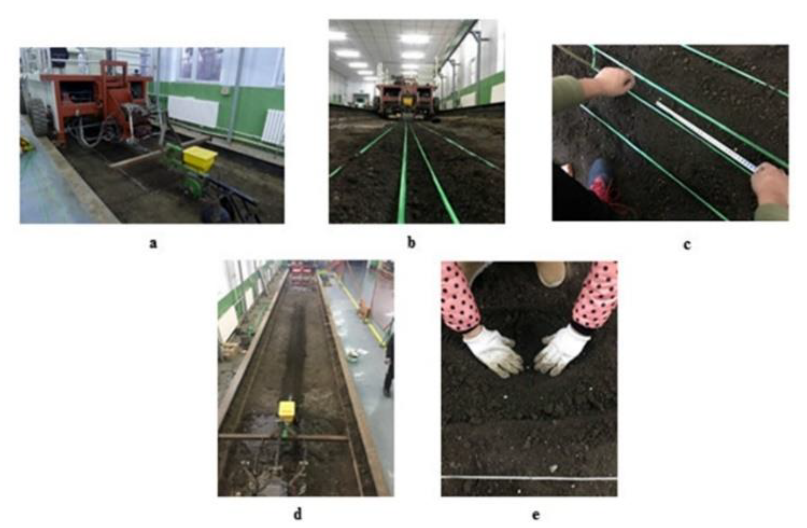
2.1.1. Soil Covering Test

In order to analysis the influence of covering on soil displacement, the soil bin test was achieved in the agricultural machinery laboratory of Jilin University. The electric frequency conversion four-wheel drive tractor and the soybean precision seeding unit with the covering discs are shown in Figure 2a. The horizontal displacement of soybean seeds and the vertical displacement of soybean seeds (mm) were considered in the soil bin test. Moreover, the vertical direction was the forward motion direction of the tractor, and the horizontal direction was perpendicular to the forward direction. In addition, the soil bin tests were performed at a variety of forward velocities (0.75 m/s, 1.11 m/s and 1.47 m/s) and open angles of the covering discs (50°, 60° and 70°). Moreover, the maximum forward velocity was limited by the length of soil bin, and the distances that was needed for acceleration and the braking process were also considered. Additionally, the open angle was the angle between one disc and the forward horizontal line. The target thickness of thecovering soil was 40 mm.
The specific test process was as follows. Firstly, the soil furrow was built by manual work and was composed of two soil ridges with a length, width and height of 4000, 150 and 60 mm, respectively, and the lateral distance between the two soil ridges was 50 mm. Hemp ropes were employed as length and width markers. The soil furrow is shown in Figure 2b. Artificial sowing was adopted, and the vertical distance between the two adjacent soybean seeds was 300 mm, as shown in Figure 2c. A total of 13 soybean seeds were needed in each trial. Each case was repeated 3 times, and the mean value of the 3 experiments was used as the seed displacement in each case. Subsequently, the marker ropes of the soil furrow were removed, and the soil covering was then finished by a covering device, as shown in Figure 2d. Finally, the covering soil above the seed was carefully uncovered by hand (Figure 2e). The vertical and horizontal displacements of seeds were measured. In addition, the distance from the hanging beam to the soil surface was 580 mm, and this distance was calibrated before each test started.

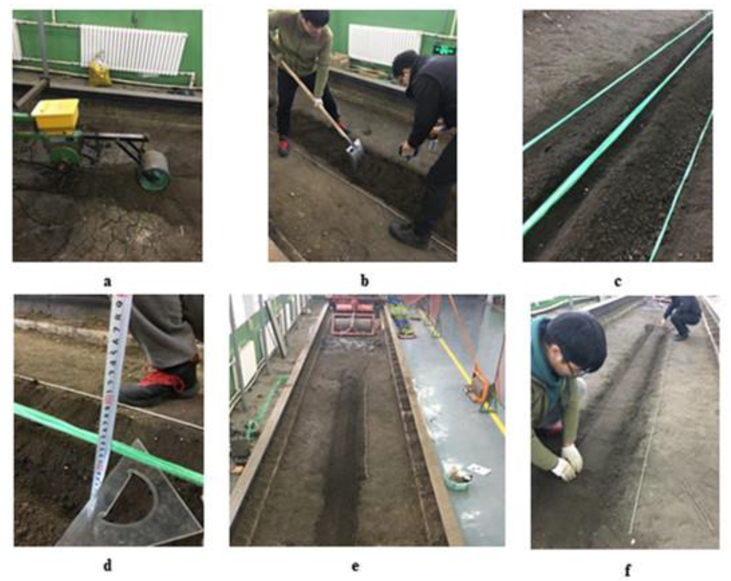
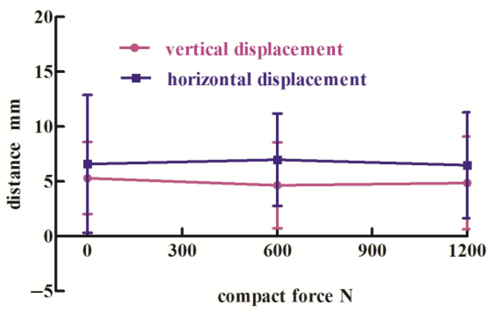
2.1.2. Soil Compacting Test

In order to analysis the influence of compacting on soil displacement, the soil bin test was achieved in the agricultural machinery laboratory. The soybean precision seeding unit with the compacting part is shown in Figure 3a. The horizontal displacement of soybean seeds, the vertical displacement of soybean seeds and the displacement of sowing depth (mm) were considered in the soil bin test. Moreover, the soil bin tests were achieved at a variety of forward velocities (0.75 m/s, 1.11 m/s and 1.47 m/s).
The specific test process was as follows. Firstly, to ensure that the soil conditions remained unchanged during the trials, it was necessary to loosen the soil before each test and measure the soil compactability before and after compacting with a soil firmness measuring instrument, as shown in Figure 3b. Then, the soil furrow was built by manual work and was composed of two soil ridges with a length, width and height of 4000, 150 and 60 mm, respectively, and the lateral distance between the two soil ridges was 50 mm. Hemp ropes were employed as length and width markers. The soil furrow is shown in Figure 3c. Artificial sowing was adopted, and the vertical distance between the two adjacent soybean seeds was 300 mm. A total of 13 soybean seeds were needed in each trial. The sowing depth was measured from the peak of the soil ridge to the furrow bottom (Figure 3d). Artificial covering was adopted, and the target thickness of the covering soil was 40 mm. In particular, when covering the soils, we tried not to disturb the original location of the seeds (Figure 3e). Then, the marker ropes of soil furrow were removed, and the soil compacting was finished by the compacting apparatus. Finally, the covering soil above the seed was carefully uncovered by hand (Figure 3f). Subsequently, the vertical, horizontal and depth displacements of the seeds were measured. Each case was repeated 3 times, and the mean value of the 3 experiments was used as the seed displacement in each case.

2.1.3. Experimental Results Analysis

For the variety of forward velocities (0.75 m/s, 1.11 m/s, 1.47 m/s), the influence of the soil covering processing on the changes in vertical and horizontal displacements of seeds is shown in Figure 4. Changes in the forward velocity had a significant influence on seed displacement during the soil covering processing. With increasing traction velocity, the vertical displacements of the seeds increased after soil covering, while the horizontal displacements decreased.
For the variety of open angles (50°, 60°, 70°), the influence of the soil covering processing on the changes in vertical and horizontal displacements of seeds is shown in Figure 5. Changes in the open angles of the covering discs had a significant influence on seed displacement during the soil covering processing. With the increase in the open angle of the soil covering discs, the vertical and horizontal displacements of seeds decreased after soil covering.
The heap soil phenomena, after soil covering with a variety of open angles of the discs, are shown in Figure 6. The heap soil degree was relieved with increased open angles of the soil covering discs. This indicated that the larger the opening angle of the soil covering discs was, the smaller the disturbance to the soil would be. The results were consistent with those in Figure 5.
For the variety of forward velocities (0.75 m/s, 1.11 m/s, 1.47 m/s), the influence of the soil compacting processing on the changes in vertical and horizontal displacements of seeds is shown in Figure 7. The changes in the vertical and horizontal displacements of seeds after compacting were not obvious with the variety of forward velocities.
For the variety of forward velocities (0.75 m/s, 1.11 m/s, 1.47 m/s), the influence of the soil compacting processing on the changes in sowing depth of the seeds is shown in Figure 8. The changes in the sowing depth of the seeds after compacting were not significant. The sowing depth always fluctuated within the theoretical sowing depth range from 30 mm to 50 mm.

2.2. Simulation Study

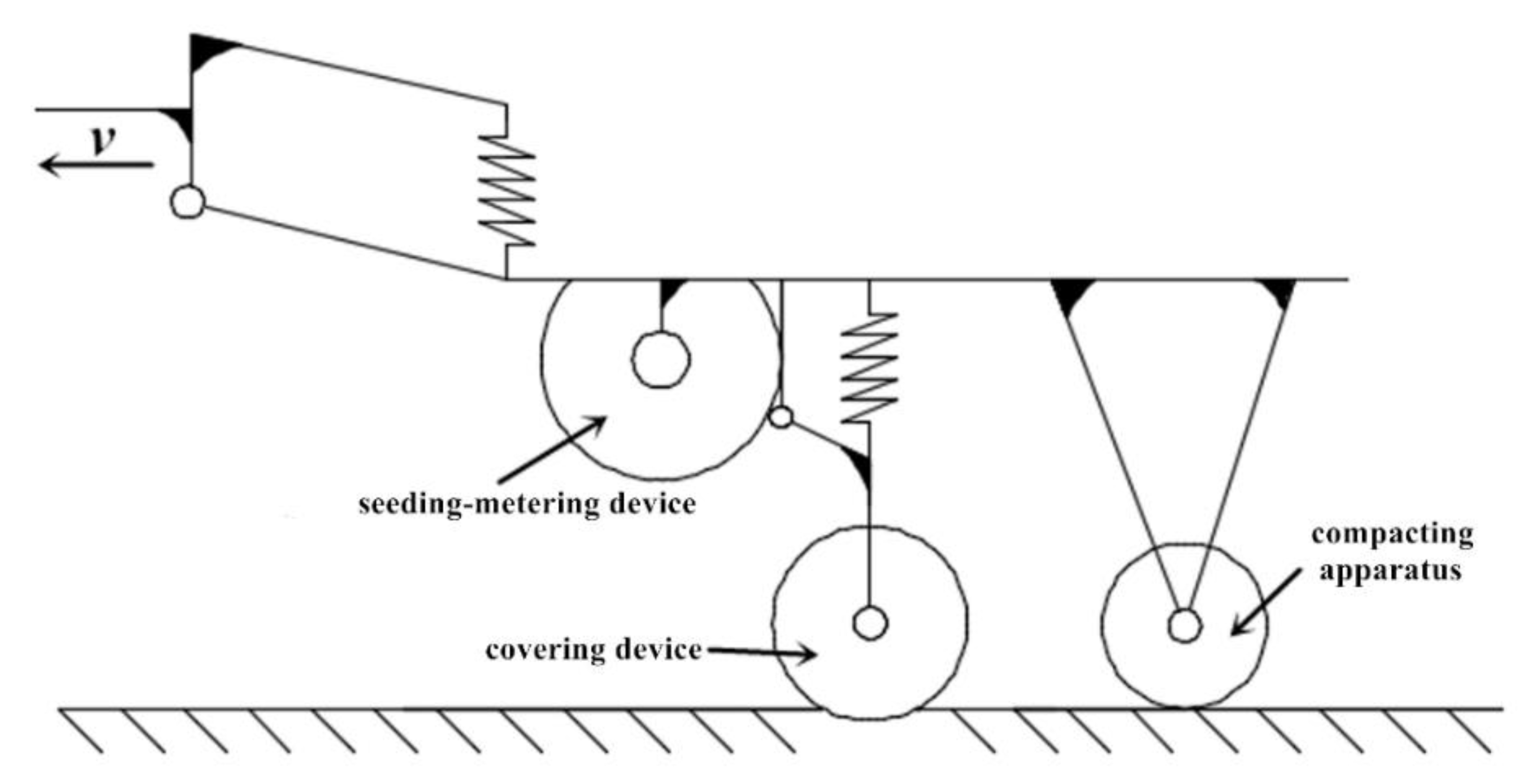
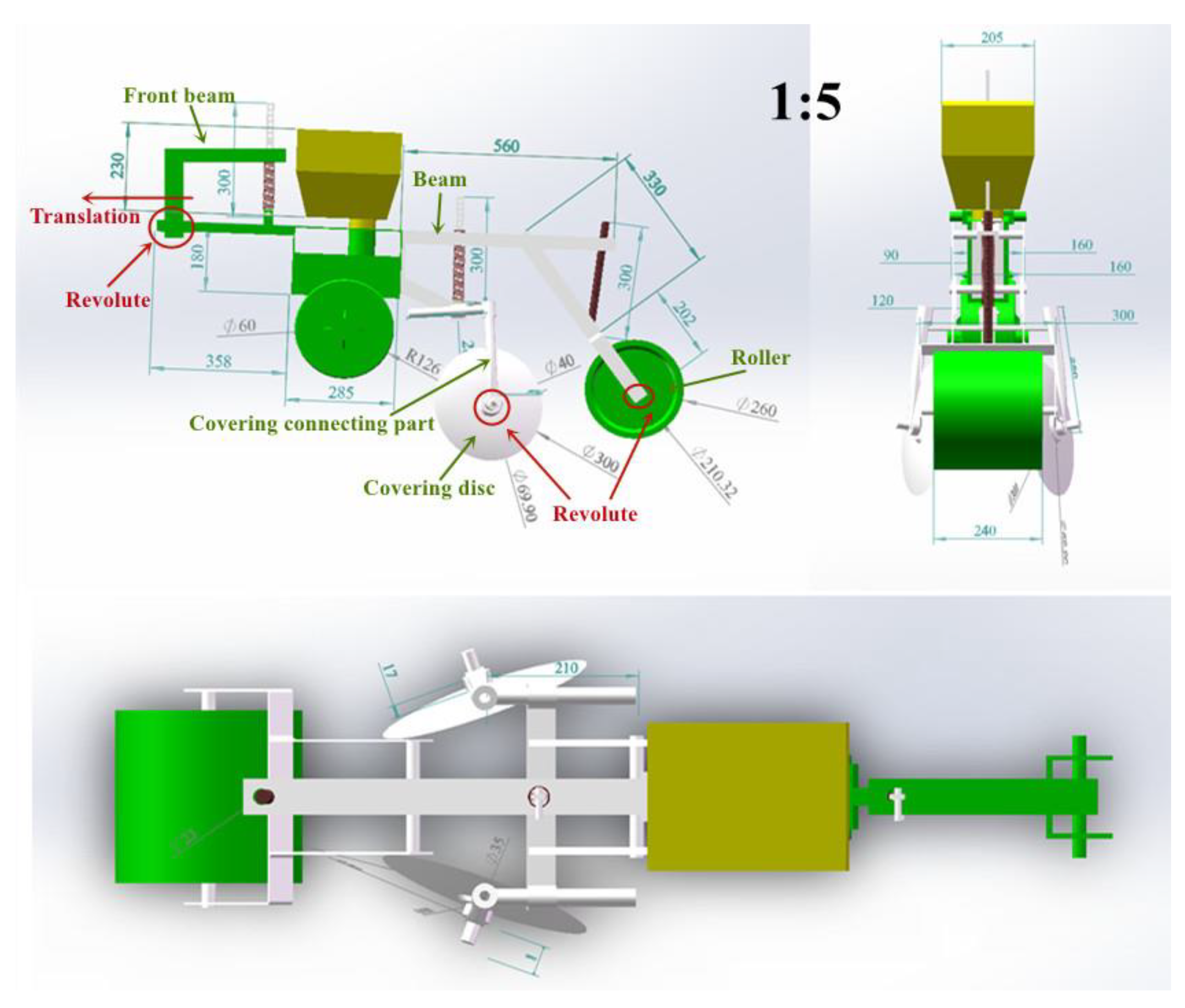
2.2.1. Precision Seeding Unit Modeling

A 3D model of the precision seeding unit is shown in Figure 9. It was stored in the format of “x_t”. This “x_t” file was then imported with the DEM-MBD coupling interface licensed software, and the precision seeding unit model was established.
The material properties of each component in the imported seeding unit model were defined as “steel”. Moreover, the density of steel, ρ, was 7850 kg/m3, the Poisson ratio of the steel, ν, was 0.3, the Young’s modulus, E, was 2.06 × 10¹¹ Pa. The constraints were imposed, and the details are shown in Table 2. Two springs were also imposed, which were similar to the actual precision seeding unit construction with compensation factor (curvature factor) K = 1.2129, the stiffness of the spring KF =16.7 N/mm and spring index C = 7 (where, C = D2/d, D2 is the middle diameter of the spring, and d is the diameter of the wire). In a general way, C = 4–9; while, K = (4C − 1)/(4C − 4) + 0.615/C; thus, when C = 7, K = 1.2129.
Then, the animate constraint of speed was imposed on “Joint_1”, and the function of the animate constraint was listed as 0.75 m/s, 1.11 m/s and 1.47 m/s.

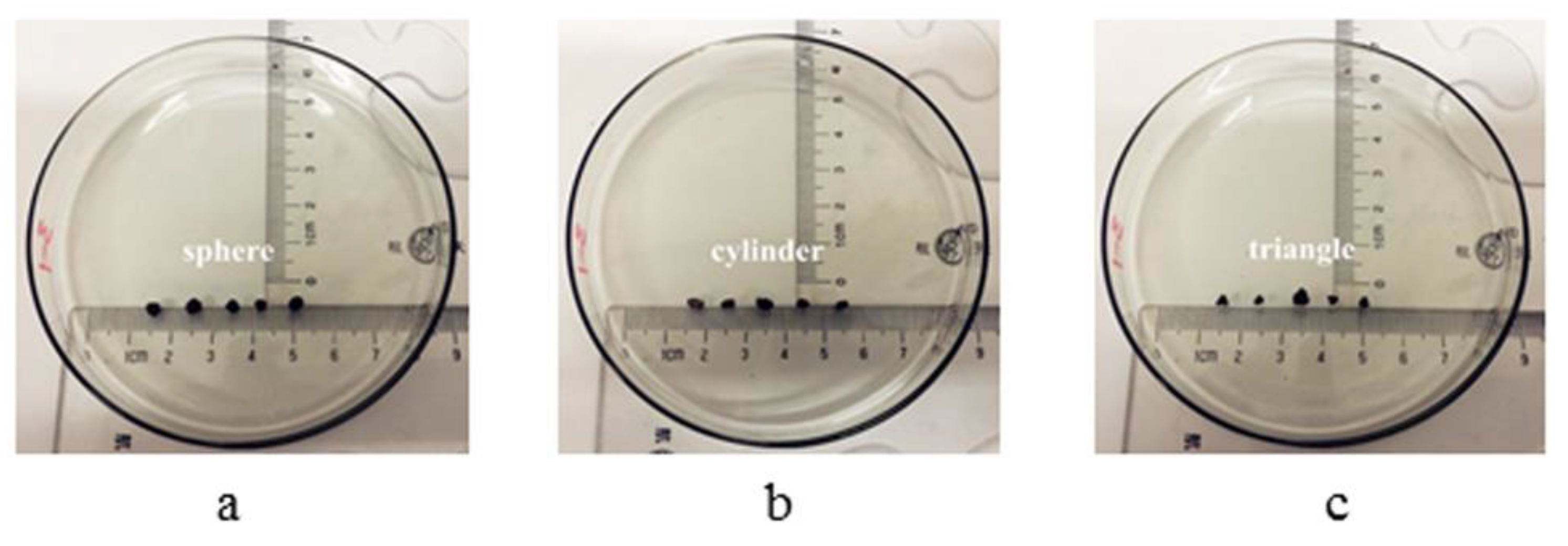
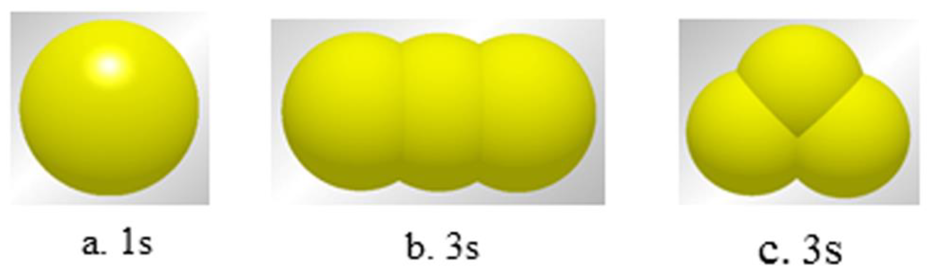
2.2.2. Particle Modeling

The precision seeding unit was imported, and the detail parameters of simulation in EDEM software are listed in Table 3. The density of the soils was determined by the pycnometer method. The values of shear modulus and Poisson’s ratio of the soils were in accordance with the literature [15]. The static friction coefficient and the rolling friction coefficient of soils were obtained by calibration. Moreover, the angle of repose test was adopted. The particle model of a soybean seed used in the simulation was the 5-sphere model, as shown in Figure 10. The other simulation parameters were in accordance with the literature [16].
Soil particle modeling: the Hertz-Mindlin+JKR model was used to describe cohesion between soil particles [17,18,19,20]. The sizes of the soil particles were larger than the actual ones, or the computational time was a high cost in the simulation. The multi-spheres method and particle size amplification were employed as simple and highly efficient methods [21,22,23]. Moreover, it was observed that the shapes of the actual soil particles were irregular, and the representative ones were as shown in Figure 11. Representing the shape of a particle is the key to DEM analysis. The mechanical behavior of granular systems is strongly influenced by particle shape, which is known as the primary characteristic of granular materials [24]. Most particles are non-spherical; they can be represented by ellipsoids [25], super-quadrics [26] and polyhedrons [27,28]. However, the contact detection algorithms for both ellipsoids and super-quadrics are complicated, which leads to a long computational time [29]. Currently, many researchers use the multi-sphere (MS) method to build the non-spherical particle model. In this paper, the soil particle radius was magnified to 10 mm, and the multi-spheres method was employed for the established soil particle. The soil particle models with different filling spheres (1-sphere, 3-sphere, 3-sphere models) in the simulation are shown in Figure 12. In order to simulate the actual soil bin situation, a total number of 1.86 million soil particles were generated in the form of normal volume distribution, and the number of each multi-sphere model accounted for one-third respectively.
The surface energy of soils (γ) was not obtained by experiment, so calibration was needed. The pilling test of soils was adopted. The value was 0.55 J/m2 for the surface energy of the soils, which was obtained by calibration. To ensure that the numerical calculation converged and was stable, the time-step in simulation was 1 × 10⁻⁵ s.
Furthermore, 7 soybean seed factories (boxes) were successively located above the soil surface that had already been generated, and the coordinates of the centers of mass of the soybean particle factories are listed in Table 4. Additionally, soil particles were generated again for establishing soil furrows (the two soil particle factories of the furrows were the same dimensions, with a length of 2500 mm, width of 100 mm and thickness of 400 mm; the coordinates of the soil particle factory centers of mass were X2200, Y100, Z20; X2200, Y100, Z170). The dimensions of the furrows in the simulation were similar to the experimental ones.
The actual coordinates of the soybean seeds generated in the simulation are listed in Table 5. The coordinates of the actual generated soybean seed particles were subtly different from the expected ones, from the comparison between Table 4 and Table 5. This was due to the roughness of the soil surface, as well as the rolling and bouncing of the soybean seeds after being randomly generated from the seed particle factories with a certain height.
The link coupling service was then started. To improve the computing efficiency, the dynamic domain computing method was adopted. The computational time of the multi-body dynamic software was set to 0.001, and the total coupling simulation time was 1.5 s for each case. The CPU calculation time cost was nearly 72 h for each coupling simulation. The EDEM version was DEM Solutions EDEM 2018.

3. Discussion

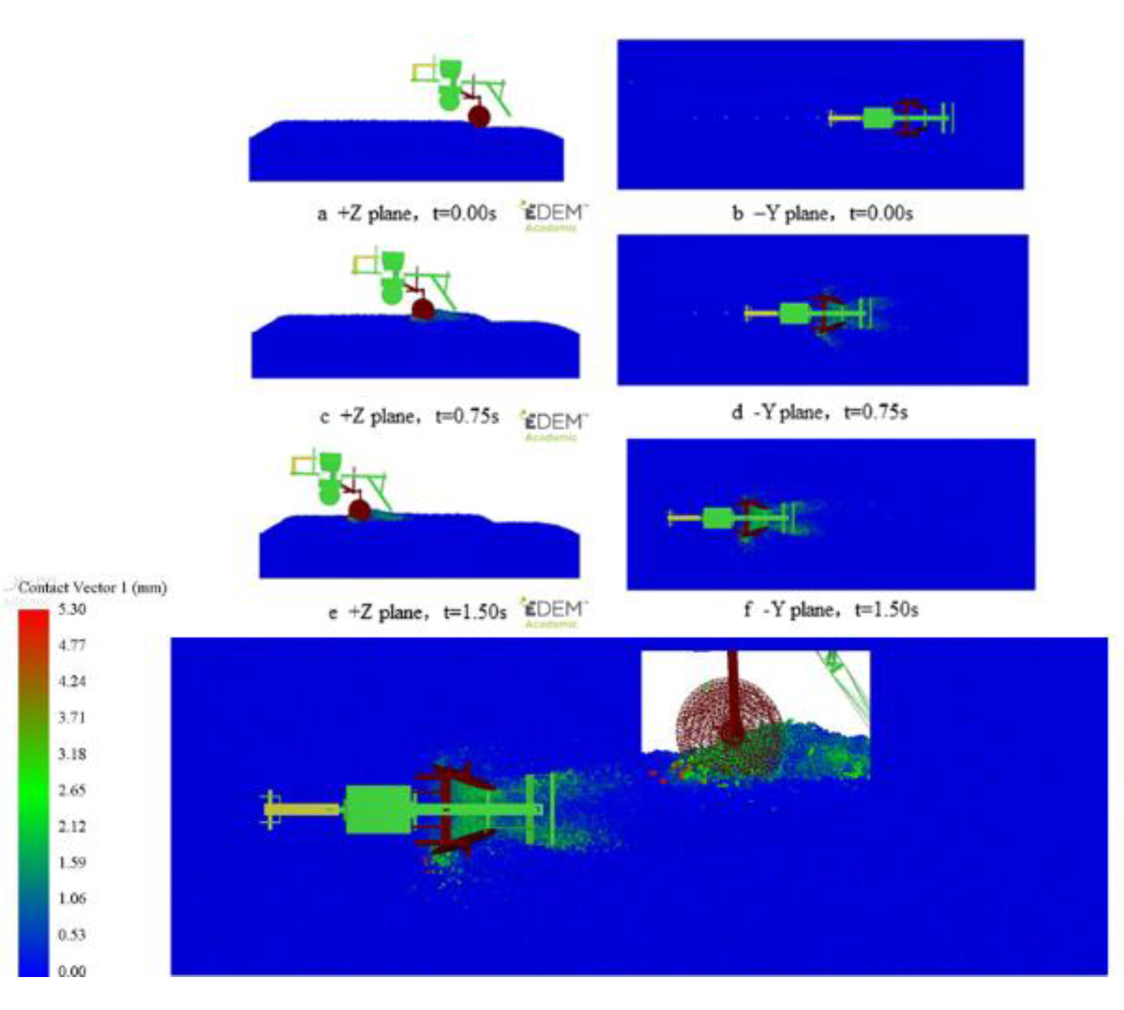
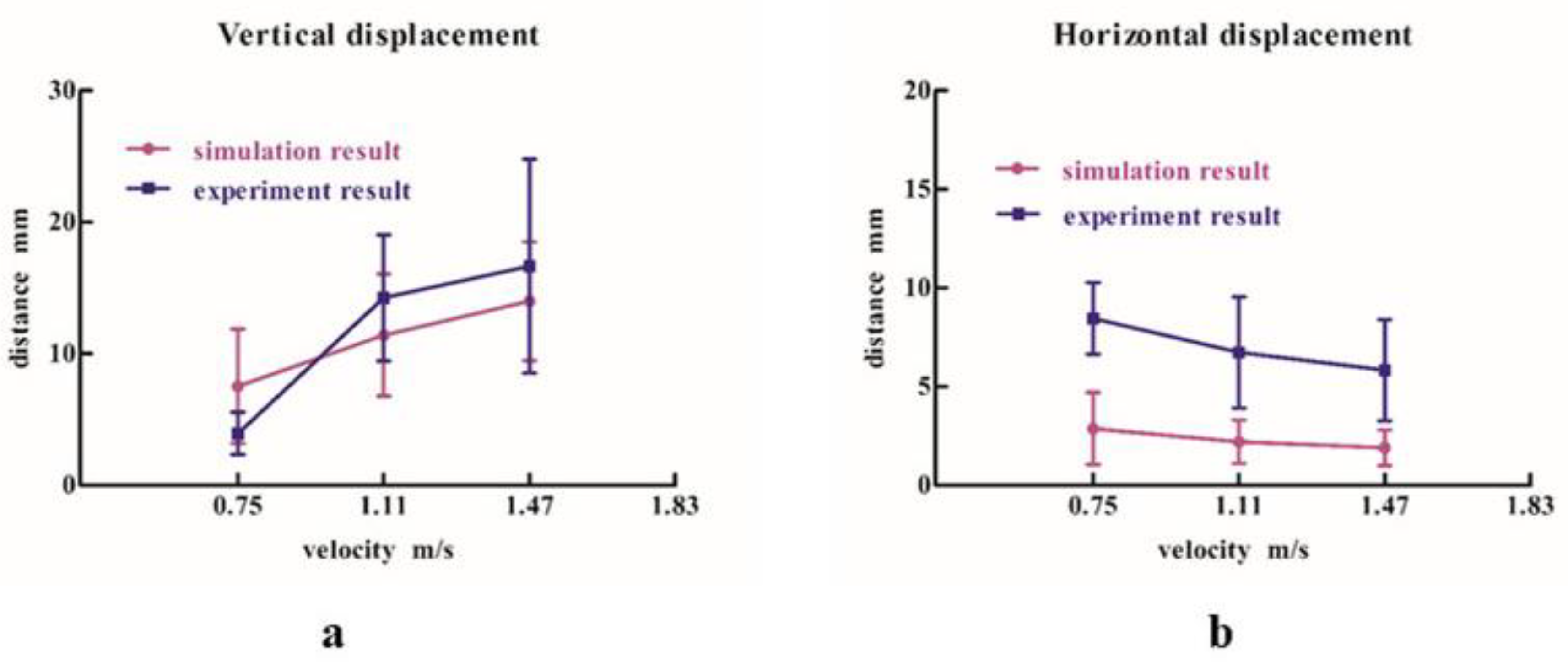
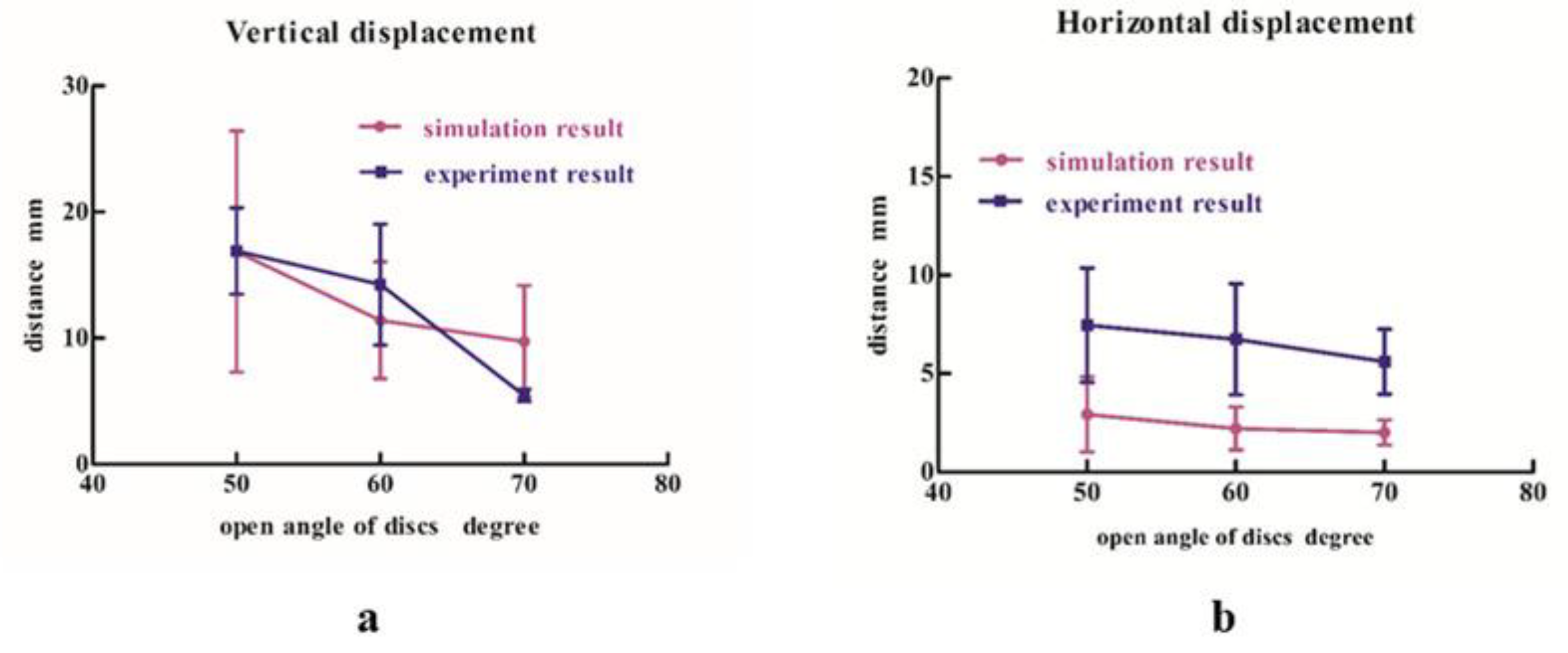
3.1. Comparison between the Simulated Results and the Experimental Results of the Soil Covering Test

Screenshots of the soil covering simulation are shown in Figure 13, with a forward velocity of 1.11 m/s and an open angle of the soil covering discs of 60°. To easily observe the contact action between discs and soils, the soil particles were given various colors for the variety of velocities and contact vectors. The changes in soil disturbance according to the precision seeding units at different times were observed.
Soil particles obtained larger instantaneous velocities when the contact action between the discs and the soils occurred. This was due to the forward velocity of the apparatus and the peripheral speed produced by the rotation of the discs. When the forward velocity was 0.75 m/s, the maximum velocity of the soil particle was 1.49 m/s. When the forward velocity was 1.11 m/s, the maximum velocity of the soil particle was 1.84 m/s. When the forward velocity was 1.47 m/s, the maximum velocity of the soil particle was 1.96 m/s.
The comparisons of the displacements of seeds after soil covering for the variety of forward velocities between simulations and experiments are shown in Figure 14. The simulated results were close to those from the experiments. With increasing traction velocity, the vertical displacements of seeds increased after soil covering, while the horizontal displacements decreased. The feasibility of the coupling method was verified.
The comparisons of displacements of seeds after soil covering for the variety of open angles of the soil covering discs between simulations and experiments are shown in Figure 15. The conclusions of simulations were consistent with those of the experiments. With increasing open angles of soil covering discs, the vertical and horizontal displacements of seeds decreased after soil covering.

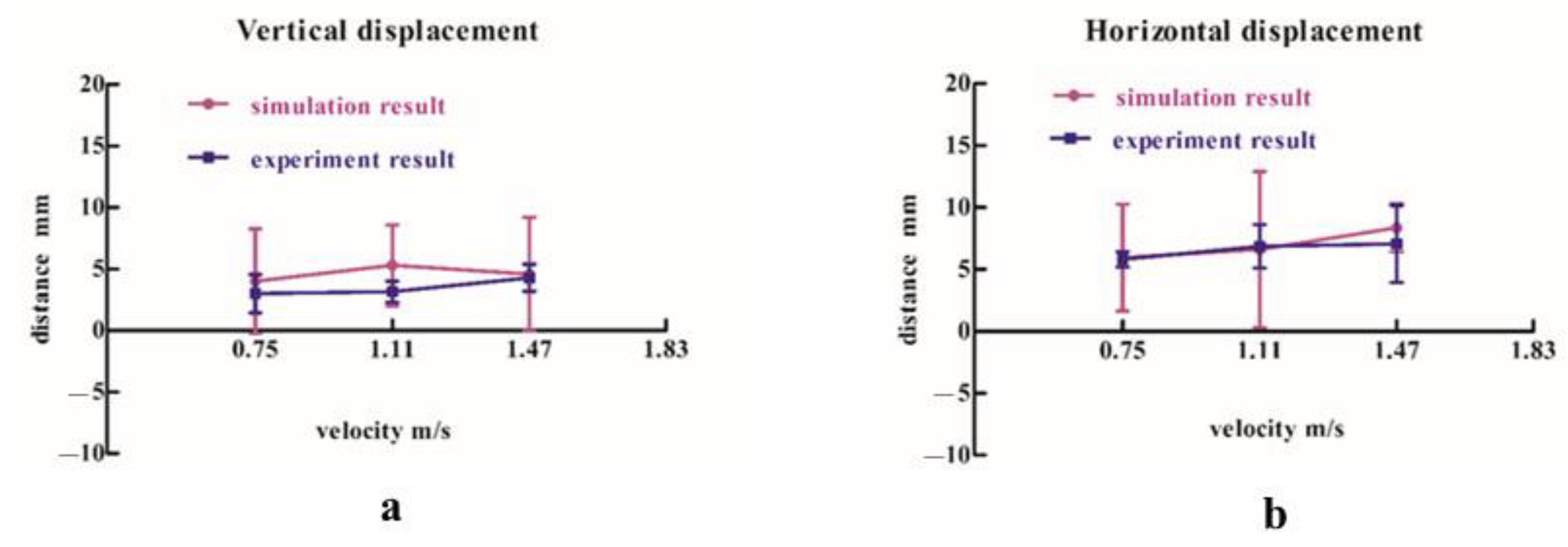
3.2. Comparison between the Simulated Results and the Experimental Results of Soil Compacting Test

The screenshots of the soil compacting simulation are shown in Figure 16, with the forward velocity of 1.11 m/s. The display of the precision seeding unit in the +Z direction was set to mesh. Changes in the soil disturbance were observed according to the precision seeding unit at different times (t = 0.00 s, t = 0.75 s, t = 1.50 s). Moreover, the detailed view of the contact between soils and compacting apparatus is also shown in Figure 16d.
The comparisons of the displacements of seeds after soil compacting for the variety of forward velocities between simulations and experiments are shown in Figure 17. The simulation results were very close to the experiment results. Changes in the vertical and horizontal displacements of seeds after compacting were not obvious with the variety of forward velocities. The feasibility of the coupling method is further verified.
The displacements of seeds after soil compacting for the variety of compacting forces (0 N, 600 N, 1200 N) are shown in Figure 18. Changes in the vertical and horizontal displacements of seeds after compacting were not obvious with the variety of compacting forces.

4. Conclusions

The coupling method of the DEM with MBDs was adopted for simulating the soil covering and compacting working processes, based on soil bin tests. The contact actions between seed–soil and soil-working apparatus were analyzed from the micro perspective. The comparison between the simulated results and the experimental results showed that the trend was similar and the two results were close. As such, the feasibility and applicability of the coupling method were verified. The influence of seed displacement during the soil covering and compacting working processing was also analyzed. It provided a reference for analysis of precise seeding monomers. The conclusions are as follows:
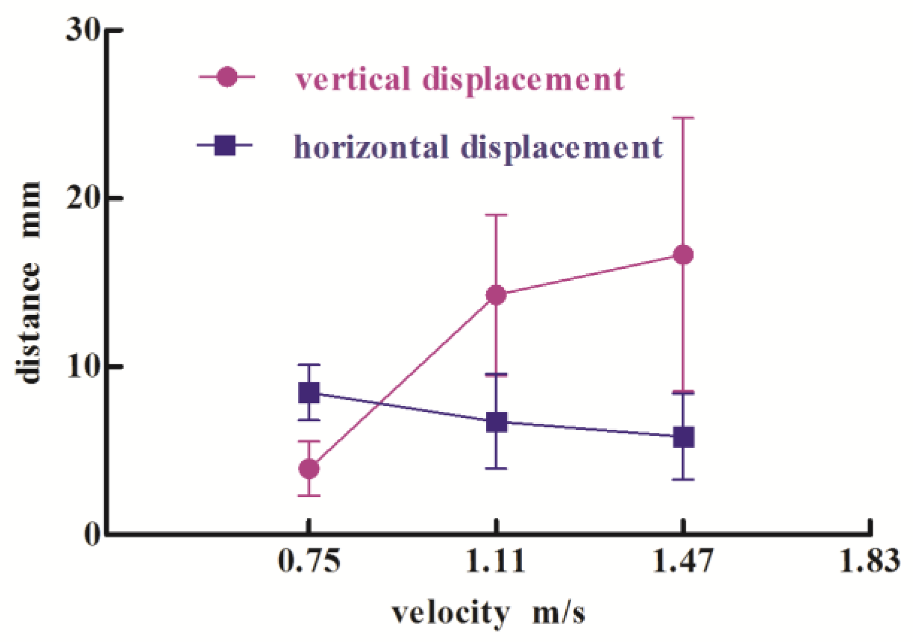
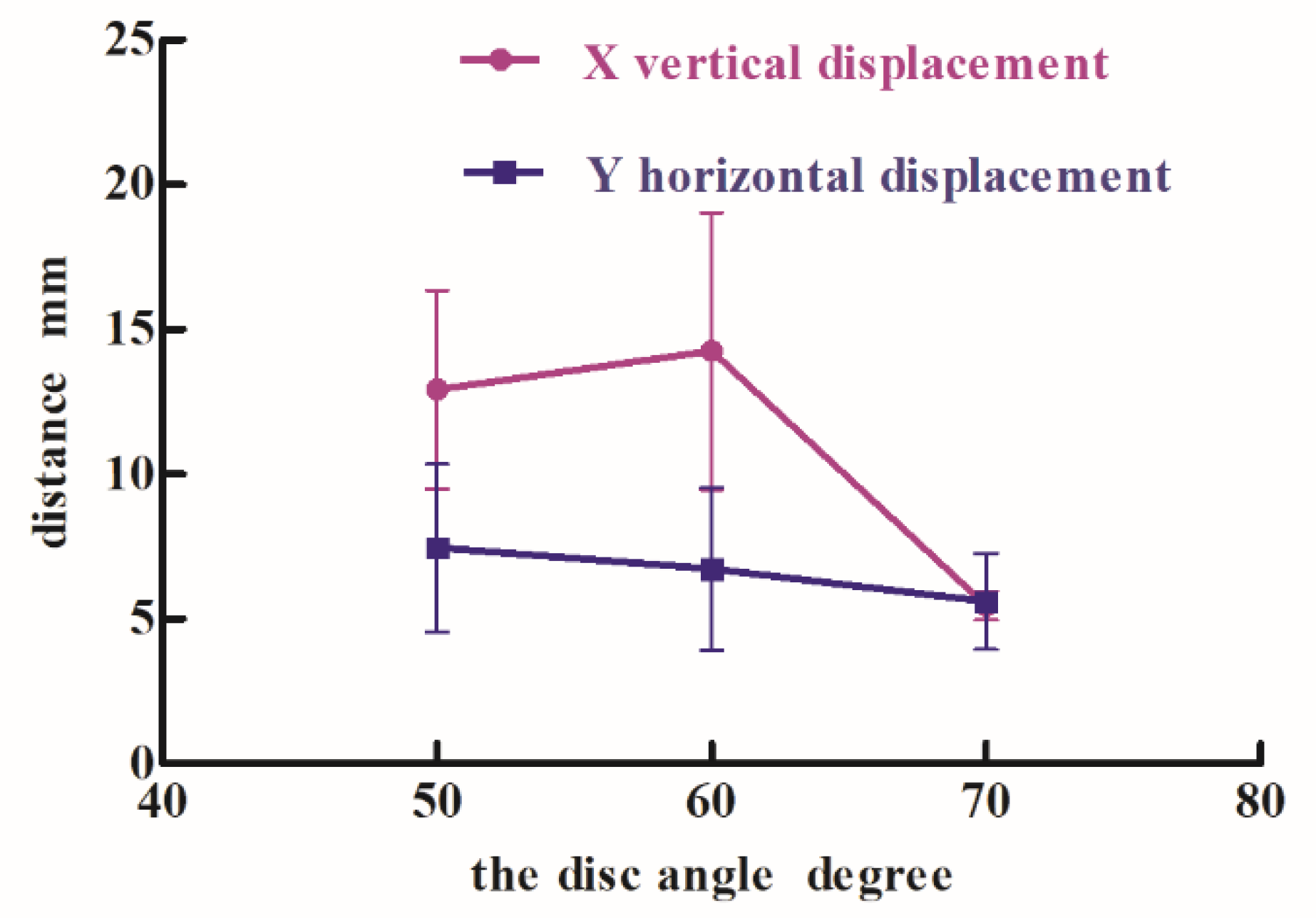
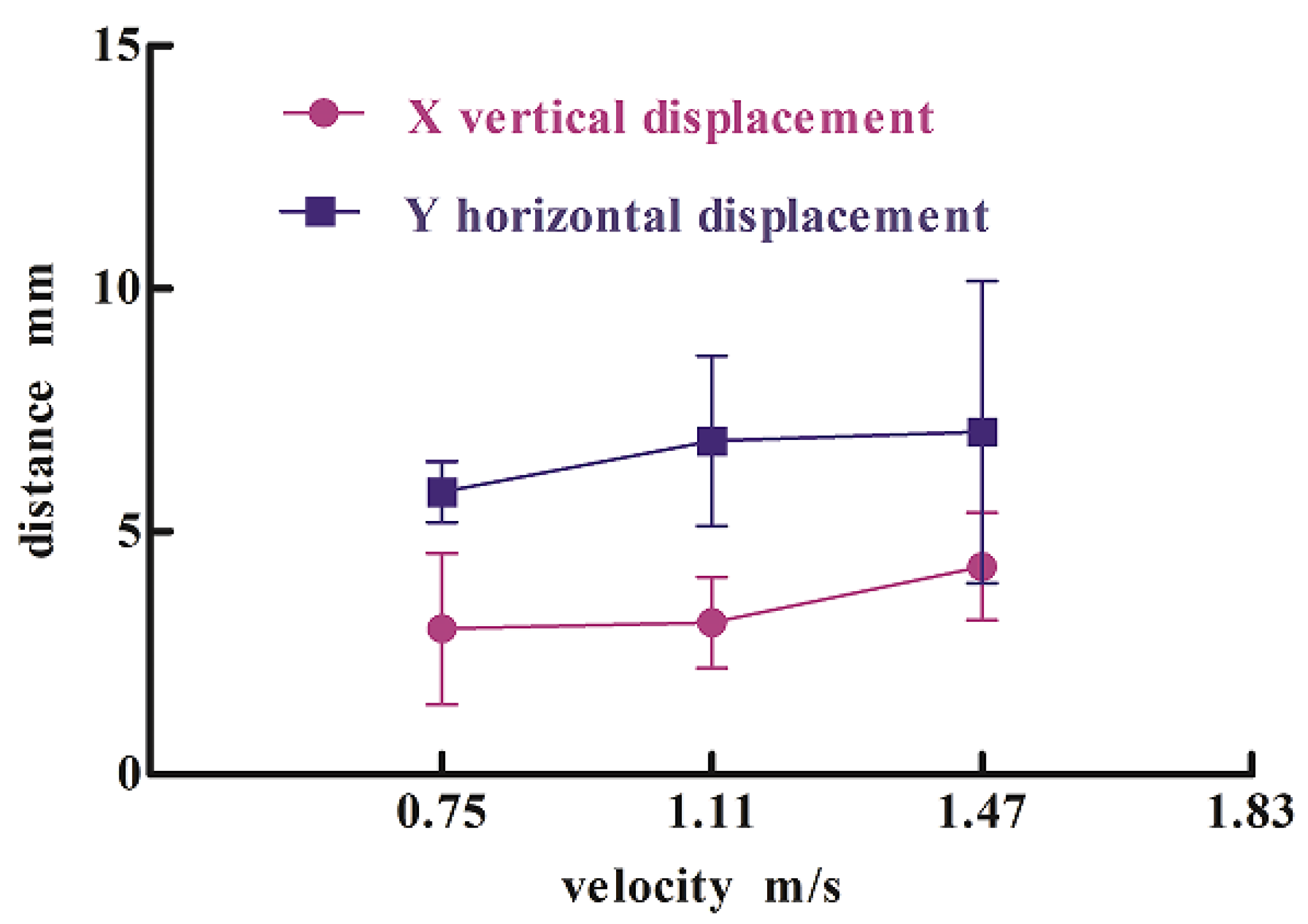
  • With increasing forward velocity, the vertical displacement of seeds after soil covering increased, while the horizontal displacement decreased. The changes in the open angle of the soil covering discs had a significant effect on seed displacement. With increasing open angles of soil covering discs, the vertical and horizontal displacements of seeds decreased.
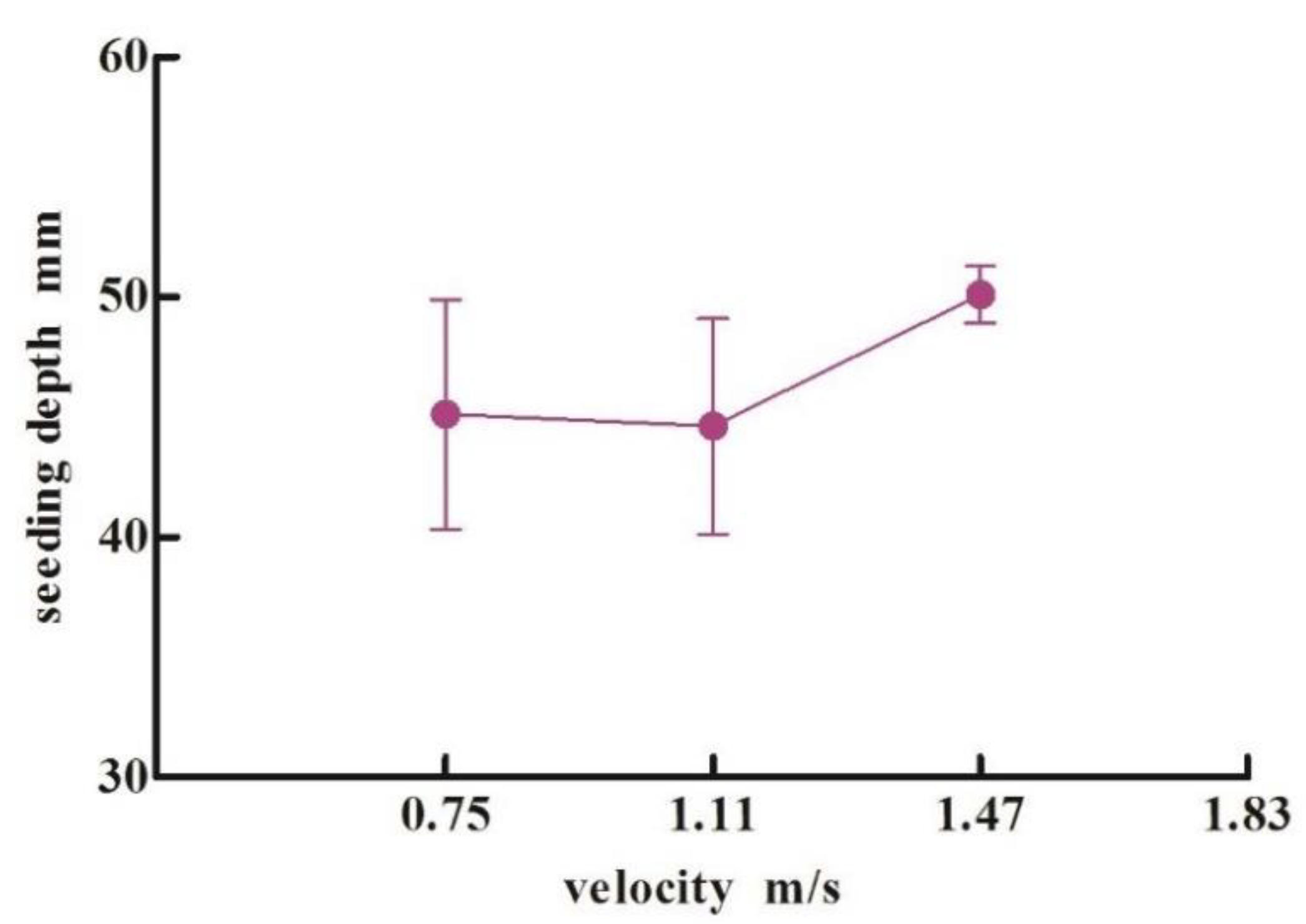
  • With increasing forward velocity, the changes in the vertical and horizontal displacements of seeds after soil compacting appeared non-significant and similar to the seeding depths of the seeds. The seeding depths for the variety of forward velocities were always fluctuating in the range from 30 mm to 50 mm within the theoretical seeding depth.
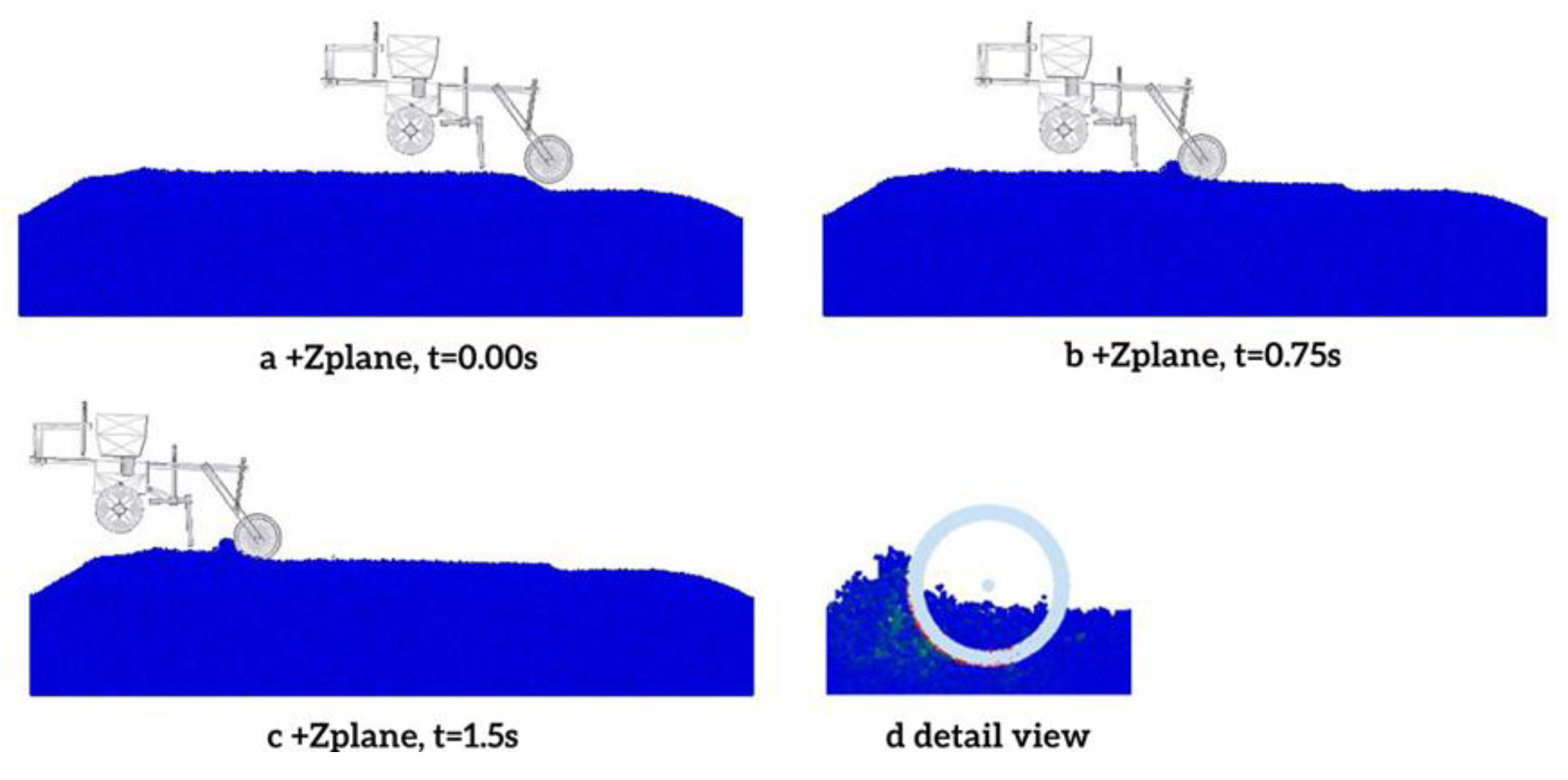
  • The soil covering and compacting working processing was simulated and analyzed by the coupling model of the DEM with MBDs. The comparison between the simulated results and the experimental results showed that the trend was similar and the two results were close. Thus, the feasibility and applicability of the coupling method were verified. It provided a new method for the design and optimization of covering and compacting components in precise seeding monomers.
  • Further information about the paper is in the following: the other working apparatus (opener, seeding device, fertilizer drill, etc.) should be analyzed by experiments and simulations; a more complicated model of the precision seeding unit should be established by the coupling method of the DEM with MBDs. The organic matters, such as crop root residues, should be considered when soil modeling.

Author Contributions

Conceptualization, J.W. and T.X.; methodology, R.Z.; software, T.X. and Y.W.; validation, W.F., X.J. and R.Z.; formal analysis, T.X.; investigation, R.Z.; resources, W.F.; data curation, Y.W. and R.Z.; writing—original draft preparation, T.X.; writing—review and editing, T.X.; visualization, X.J.; supervision, J.W.; project administration, J.W.; funding acquisition, J.W. All authors have read and agreed to the published version of the manuscript.

Funding

This research was funded by Key Research Projects of the Ministry of Science and Technology of the People’s Republic of China, grant number: 2016YFC0501200.

Institutional Review Board Statement

The study did not require ethical approval.

Informed Consent Statement

Not applicable.

Data Availability Statement

The study did not report any data.

Acknowledgments

In this paper, we received technical support from the College of biological and agricultural engineering in Jilin University, including the Licensed software of EDEM and the coupling interface.

Conflicts of Interest

The authors declare no conflict of interest.

References

  1. Gao, X.; Zhou, Z.; Xu, Y.; Yu, Y.; Su, Y.; Cui, T. Numerical simulation of particle motion characteristics in quantitative seed feeding system. Powder Technol. 2020, 367, 643–658. [Google Scholar] [CrossRef]
  2. Yang, L.; Yan, B.; Zhang, D.; Zhang, T.; Zhang, Y.; Cui, T. Research progress on precision planting technology of maize. Trans. Chin. Soc. Agric. 2016, 11, 38–48. [Google Scholar]
  3. Sun, K.; Yu, J.; Liang, L.; Wang, Y.; Yan, D.; Zhou, L.; Yu, Y. A DEM-based general modelling method and experimental verification for wheat seeds. Powder Technol. 2022, 401, 117353. [Google Scholar] [CrossRef]
  4. Zhou, H.; Chen, Y.; Sadek, M.A. Modelling of soil–seed contact using the Discrete Element Method (DEM). Biosyst. Eng. 2014, 121, 56–66. [Google Scholar] [CrossRef]
  5. Bufton, L.P.; Richardson, P.; O’Dogherty, M.J. Seed displacement after impact on a soil surface. J. Agric. Eng. Res. 1974, 19, 327–338. [Google Scholar] [CrossRef]
  6. Abdolahzare, Z.; Mehdizadeh, S.A. Real time laboratory and field monitoring of the effect of the operational parameters on seed falling speed and trajectory of pneumatic planter. Comput. Electron. Agric. 2018, 145, 187–198. [Google Scholar] [CrossRef]
  7. Nielsen, S.K.; Munkholm, L.J.; Lamandé, M.; Nørremark, M.; Gareth, T.C.; Green, E.O. Seed drill depth control system for precision seeding. Comput. Electron. Agric. 2018, 144, 174–180. [Google Scholar] [CrossRef]
  8. Jia, H.; Wang, W.; Luo, X.; Zheng, J.; Guo, M.; Zhuang, J. Effects of profiling elastic press roller on seedbed properties and soybean emergence under double row ridge cultivation. Soil Tillage Res. 2016, 162, 34–40. [Google Scholar] [CrossRef]
  9. Gürsoy, S.; Türk, Z. Effects of land rolling on soil properties and plant growth in chickpea production. Soil Tillage Res. 2019, 195, 104425. [Google Scholar] [CrossRef]
  10. Tong, J.; Zhang, Q.; Guo, L.; Chang, Y.; Guo, Y.; Zhu, F.; Chen, D.; Liu, X. Compaction Performance of Biomimetic Press Roller to Soil. J. Bionic Eng. 2015, 12, 152–159. [Google Scholar] [CrossRef]
  11. Jingli, W. The Research of Displacement Control after Seed Contacting Soil in the Process of Soil Covering and Rolling with Precision Seeder; JinLin University: Changchun, China, 2012. [Google Scholar]
  12. Jin, T.; Qingzhu, Z.; Yuan, C.; Mo, L.; Leilei, Z.; Xin, L. Finite element analysis and experimental verification of bionic press roller in reducing adhesion and resistance. Trans. Chin. Soc. Agric. Mach. 2014, 7, 85–92. [Google Scholar]
  13. Hui, G. Study on Maize Sowing Quality Evaluation and Soil Covering-Compacting Device; JinLin University: Changchun, China, 2019. [Google Scholar]
  14. Sadeghi-Chahardeh, A.; Mollaabbasi, R.; Picard, D.; Taghavi, S.M.; Alamdari, H. Discrete Element Method Modeling for the Failure Analysis of Dry Mono-Size Coke Aggregates. Materials 2021, 14, 2174. [Google Scholar] [CrossRef] [PubMed]
  15. Wang, Y.; Ganwei, C.; Jian, Y. Dynamics simulation of direct shear test. Trans. Chin. Soc. Agric. Mach. 2011, 7, 96–101. [Google Scholar] [CrossRef]
  16. Xu, T.; Yu, J.; Yu, Y.; Wang, Y. A modelling and verification approach for soybean seed particles using the discrete element method. Adv. Powder Technol. 2018, 29, 3274–3290. [Google Scholar] [CrossRef]
  17. Horváth, D.; Poós, T.; Tamás, K. Modeling the movement of hulled millet in agitated drum dryer with discrete element method. Comput. Electron. Agric. 2019, 162, 254–268. [Google Scholar] [CrossRef]
  18. Chen, X.; Elliott, J.A. On the scaling law of JKR contact model for coarse-grained cohesive particles. Chem. Eng. Sci. 2020, 227, 115906. [Google Scholar] [CrossRef]
  19. Zhou, J.; Zhang, L.; Hu, C.; Li, Z.; Tang, J.; Mao, K.; Wang, X. Calibration of wet sand and gravel particles based on JKR contact model. Powder Technol. 2022, 397, 117005. [Google Scholar] [CrossRef]
  20. Feng, X.; Liu, T.; Wang, L.; Yu, Y.; Zhang, S.; Song, L. Investigation on JKR surface energy of high-humidity maize grains. Powder Technol. 2021, 382, 406–419. [Google Scholar] [CrossRef]
  21. Yaron, F.; Rubinstein, D.; Shmulevich, I. Determination of discrete element model parameters for soil-bulldozer blade interaction. In Proceedings of the 15th International Conference of the ISTVS, Hayama, Japan, 25–29 September 2005; pp. 25–29. [Google Scholar]
  22. Asaf, Z.; Shmulevich, I.; Rubinstein, D. Predicting soil-rigid wheel performance using distinct element methods. Trans. ASABE 2006, 49, 607–616. [Google Scholar] [CrossRef]
  23. Tamás, K.; Bernon, L. Role of particle shape and plant roots in the discrete element model of soil–sweep interaction. Biosyst. Eng. 2021, 211, 77–96. [Google Scholar] [CrossRef]
  24. Sadeghi-Chahardeh, A.; Mollaabbasi, R.; Picard, D.; Taghavi, S.M.; Alamdari, H. Effect of Particle Size Distributions and Shapes on the Failure Behavior of Dry Coke Aggregates. Material 2021, 14, 5558. [Google Scholar] [CrossRef] [PubMed]
  25. Ouadfel, H.; Rothenburg, L. An algorithm for detecting inter-ellipsoid contacts. Comput. Geotech. 1999, 24, 245–263. [Google Scholar] [CrossRef]
  26. Cleary, P.W.; Stokes, N. Efficient Collision Detection for Three Dimensional Super-ellipsoidal Particles. In Proceedings of the 8th International Computational Techniques and Applications Conference: CTAC97, Singapore, 29 September–1 October 1997. [Google Scholar]
  27. Cundall, P.A. Formulation of a three-dimensional distinct element model—Part I. A scheme to detect and represent contacts in a system composed of many polyhedral blocks. Int. J. Rock Mech. Min. Sci. Geomech. Abstr. 1988, 25, 107–116. [Google Scholar] [CrossRef]
  28. Govender, N.; Wilke, D.N.; Kok, S.; Els, R. Development of a convex polyhedral discrete element simulation framework for NVIDIA Kepler based GPUs. J. Comput. Appl. Math. 2014, 270, 386–400. [Google Scholar] [CrossRef]
  29. Kruggel-Emden, H.; Rickelt, S.; Wirtz, S.; Scherer, V. A study on the validity of the multi-sphere discrete element method. Powder Technol. 2008, 188, 153–165. [Google Scholar] [CrossRef]
Figure 1. Motion diagram of the seeding mechanism.
Processes 10 01103 g001
Figure 2. Soil bin test for covering. (a) seeding unit with covering discs; (b) artificial construction of soil furrow; (c) artificial sowing; (d) covering soils with precision seeding unit; (e) uncovering the seeds by hand.
Processes 10 01103 g002
Figure 3. Soil bin test of compacting. (a) Soil sample preparation (soil loosening and testing firmness before each trial); (b) seeding unit with the compacting component; (c) artificial construction of soil furrow; (d) recording the positions of the seeds; (e) covering soil not disturbing the seeds; (f) uncovering the seeds after compacting.
Processes 10 01103 g003
Figure 4. The influence of the soil covering processing on the changes in seed displacement with various forward velocities.
Processes 10 01103 g004
Figure 5. The influence of the soil covering process on the changes in seed displacement with various open angles of discs.
Processes 10 01103 g005
Figure 6. Heap soil phenomenon after soil covering with various open angles of the discs. (a) heap soil phenomenon after soil covering with 50 degree of the discs; (b) heap soil phenomenon after soil covering with 60 degree of the discs; (c) heap soil phenomenon after soil covering with 70 degree of the discs.
Processes 10 01103 g006
Figure 7. The influence of the soil compacting processing on the changes in seed displacement with various forward velocities.
Processes 10 01103 g007
Figure 8. The influence of the soil compacting process on the changes in sowing depth with various forward velocities.
Processes 10 01103 g008
Figure 9. A 3D model of the precision seeding unit with constrains presented.
Processes 10 01103 g009
Figure 10. The 5-sphere model of a soybean seed in the DEM.
Processes 10 01103 g010
Figure 11. Representative types of actual soil particles.
Processes 10 01103 g011
Figure 12. The soil particle models with different filling spheres (1-sphere, 3-sphere, 3-sphere models) in simulation.
Processes 10 01103 g012
Figure 13. Screenshots of the soil covering simulation.
Processes 10 01103 g013
Figure 14. Comparisons of displacements of seeds after soil covering for the variety of forward velocities between simulations and experiments.
Processes 10 01103 g014
Figure 15. Comparisons of displacements of seeds after soil covering for the variety of open angles of the soil covering discs between simulations and experiments.
Processes 10 01103 g015
Figure 16. The screenshots of the soil-compacting simulation.
Processes 10 01103 g016
Figure 17. Comparisons of the displacements of seeds after soil compacting for the variety of forward velocities between simulations and experiments.
Processes 10 01103 g017
Figure 18. The displacements of seeds after soil compacting for the variety of compacting forces (0 N, 600 N, 1200 N).
Processes 10 01103 g018
Table 1. The particle size distribution in the soils.
Granular Diameter, mmSample 1,
g
Sample 2,
g
Sample 3,
g
Mean,
g
Proportion,
%
0.05–0.14.724.454.024.402.20
0.1–0.229.9029.2527.6928.9514.48
0.2–0.311.1512.2211.0511.475.74
0.3–0.4540.3042.3740.8041.1620.58
0.45–149.4351.8251.3450.8625.43
1–228.5231.4438.3832.7816.39
≥211.547.958.399.294.65
Table 2. Type of imposed constraint in the working process.
No.Connector ObjectType of Connectors
Joint_1Front beam–groundTranslation
Joint_2Front beam–beamRevolute
Joint_3Beam–covering connecting partRevolute
Joint_4Covering connecting part–çovering disc 1/covering disc 2Revolute
Joint_5Beam–rollerRevolute
Table 3. The detailed parameters in the simulation.
ParametersSymbolSoilSteelSoybean Seed
Density (kg/m3)ρ195078501211
Poisson’s ratiov0.250.30.4
Shear modulus (Pa)G2.73 × 1067.92 × 10101.28 × 108
Restitution coefficiente0.30.50.57
Static friction coefficientμ0.50.10.2
Rolling friction coefficientμr0.030.020.01
Table 4. The coordinates of the centers of mass of the soybean particle factories.
No.xyzNo.xyz
11200.000−20.000125.00052400.000−20.000125.000
21500.000−20.000125.00062700.000−20.000125.000
31800.000−20.000125.00073000.000−20.000125.000
42100.000−20.000125.000
The +X direction is the forward direction of the tractor, which is defined as the vertical direction; the +Z direction is defined as horizontal direction; the −Y direction is the seeding depth.
Table 5. The actual coordinates of the centers of mass of the soybean seed particles generated in the simulation.
No.xyzNo.xyz
11174.600−58.115129.00052396.789−57.730120.190
21491.774−67.713138.90062683.555−59.8447117.000
31798.447−57.730119.90072988.300−73.200123.050
42097.109−69.130133.290
Publisher’s Note: MDPI stays neutral with regard to jurisdictional claims in published maps and institutional affiliations.

