
The Design and the Development of a Biped Robot Cooperation System


1
Department of Information and Telecommunications Engineering, Ming Chuan University, Taoyuan City 333, Taiwan
2
Department of Electrical Engineering, National Ilan University, Yilan 260, Taiwan
*
Author to whom correspondence should be addressed.
Processes 2022, 10(7), 1350; https://0-doi-org.brum.beds.ac.uk/10.3390/pr10071350
Submission received: 18 June 2022
/
Revised: 9 July 2022
/
Accepted: 10 July 2022
/
Published: 12 July 2022
(This article belongs to the Special Issue Application of Fuzzy Control in Computational Intelligence)
Abstract
:The aim of this paper is to design a fuzzy motion control algorithm for a developed monocular vision system based on a cooperative transportation system of two humanoid robots. The control strategies of the cooperation transportation system contain three stages, including object searching, walking toward the transported object, and cooperatively moving the transported object. To have different moving speeds, the gait step size was pre-planned as two different modes, i.e., one of the gaits is selected to let the HR have large variations of motion and another gait is to make the HR with small variations. The fuzzy motion control algorithm is utilized to select the appropriate mode of gait. Both humanoid robots can actively search and move to the front of the target object, then cooperatively lift the target and carry it to the platform. The task of synchronous movement is controlled with fuzzy techniques through the control terminal. From the experimental results, it can be seen that both robots can distinguish the orientation of the target, move to the appropriate position, and then successfully raise the target together.
1. Introduction
In recent years, the application of robots has become increasingly widespread due to the development of control technology and artificial intelligence, especially in the area of the cooperation of multi-robots [1,2,3]. Applications for multiple robot systems include assembly and painting of industrial manipulators [4,5], transportation and formation of multi mobile robots [6,7], crop harvesting of a mobile manipulator [8,9], and hybrid collaborative robot systems [10,11].
Humanoid robots are more flexible than other types of robotic systems since their firm multi-joint structure can complete more sophisticated and tedious tasks [12,13]. Especially, humanoid robots can be applied for object transportation, rescue tasks, sports competition, and logistics handling cooperation [14,15,16,17]. However, a single humanoid robot carrying a heavy object might lose the chance to complete the task successfully when the weight of the heavy object is too large. Therefore, the problem of multi-humanoid robot cooperation has been becoming a hot topic in the field of robotics [18,19,20].
In [18], the research focused on the cooperation between two robots, which is named NAO. However, the behavior of collaboratively carrying objects is based on the way of interaction between human and human. Two robots can achieve synchronous control by multithread communication under the cloud platform models. In [19], based on multi-sensor fusion, kinematics modeling, and object recognition, the authors analyze and design the dynamic identification of object position and pose, trajectory planning of robot motion, and cooperative handling control. Two NAO robots can cooperatively accomplish the task of transportation using the proposed strategies in [19]. In [20], a dynamic model that satisfies the cooperative movements is established, and the motion trajectory of two humanoid robots in the process of cooperative manipulation of objects is planned. Furthermore, the control method based on optimal parameters is adopted to optimize the energy consumption of the cooperative movements of two humanoid robots.
Since the exact model of humanoid robot is hard to obtain, the control method in [20] is not easy to implement in a real humanoid robot. Although the control strategy does not rely on the exact model of a humanoid robot in [19], more sensors, including a Zed2i binocular stereo vision sensor, a RealSense D455 deep infrared sensing camera, and several built-in sensors, are required in a humanoid robot. In [18], the distance between the object and the target is calculated using only one vision sensor. Additionally, the mathematics model is unnecessary in [18]. Moreover, that the object is cooperatively transported to the specified location by two robots is not really implemented in [18].
In this paper, a cooperative transportation system with two humanoid robots is developed. Let the humanoid robots (HRs) could walk smoothly and quickly to near the transported object (TO), a monocular vision system based on fuzzy motion control algorithm is proposed. In general, the processing time of vision analysis is large when the algorithm is implemented in a small single-board computer such as Raspberry-Pi-2. To reduce the computational complexity, the gait step size is pre-planned as two different and fixed modes, i.e., one of the gaits is selected to let the HR have a large variation of motion and another gait is to allow the HR a small variation. The fuzzy motion control algorithm is utilized to select the appropriate mode of gait. There are two stages, including the processing of image information and motion control, in the one period control process. The control performance would be affected by the large image processing time. Thus, reducing the unnecessary image processes would increase the time for the control stage to improve the control performance. Compared with other research of multi-HRs cooperative control, the contributions and novelties in this paper are summarized as follows.
- This paper proposes a study to design a biped robot cooperation system, since few literatures discuss the collaborative transportation of two humanoid bipedal robots;
- The proposed fuzzy motion controllers are not dependent on the mathematical model of humanoid robots. Furthermore, the fuzzy motion control algorithm is utilized to select the appropriate mode of gait to have a different moving speed;
- The HR can capture the environment information only using a monocular vision sensing system. Moreover, the computational complexity of the proposed algorithm is moderate such that both the image processing and the motion controller can be implemented on RPi-2.
The remainder of this paper is organized as follows. Section 2 describes the architecture of a biped robot cooperation transportation system. The motion control algorithms are developed in Section 3. Section 4 presents an experiment to verify the effectiveness of the proposed method. Finally, conclusions are presented in Section 5.
2. Architecture of Biped Robot Cooperation Transportation System
2.1. The Configuration of the Robot System
The diagram of the developed cooperation transportation system is shown in Figure 1. Two humanoid robots are considered in the developed system. Each robot includes a Raspberry Pi-based (RPi) vision system and a modified commercially available humanoid robot XYZ Bolide Y-01 (BHR). The BHR includes eighteen smart servo motors (A1-16) with a high torque ratio (max. torque 25 kg-cm) in which each hand has three degrees of freedom (DoFs) using three motors and each leg has six DoFs using six motors. All smart servo motors are controlled by an Arduino-compatible ATmega1280 microcontroller (RC2200). The RC2200 control board includes a three-axis accelerometer and a distance sensor.
Compared with the original commercially available BHR, there are two parts modified in this study, including a non-functional head that is replaced by a RPi-based vision system, and a smaller grasper is changed to be a longer homemade palm. The modified BHR has the following dimensions L: 140 mm, W: 230 mm, H: 470 mm. The RPi is utilized to capture and to analyze the image of the transported object (TO). In this study, the modified BHR can capture environmental information using only the developed RPi vision system. Moreover, the calculation of the appropriate motion and the message exchange between robots are processed in RPi. Two BHRs exchange information by the socket communication via Wi-Fi.
2.2. Image Processing
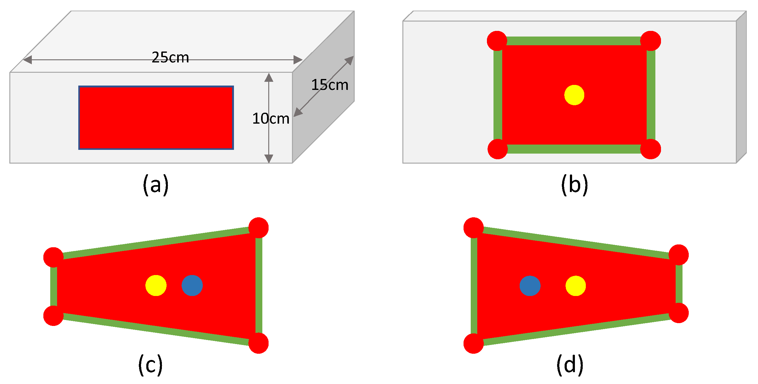
In this research, a white rectangular box is selected as a TO with a red marker attached to the corresponding sides of the box as shown in Figure 2a. The HRs can find the TO using the vision system. The vision system, which is placed on the head of the HR is shown in Figure 1, includes a Microsoft HC-3000 Webcam, a SG-90 servo motor, and Raspberry-Pi-2. The webcam is mounted on the SG-90 servo motor such that the field of view (FOV) can be maximized to by rotating the SG-90.
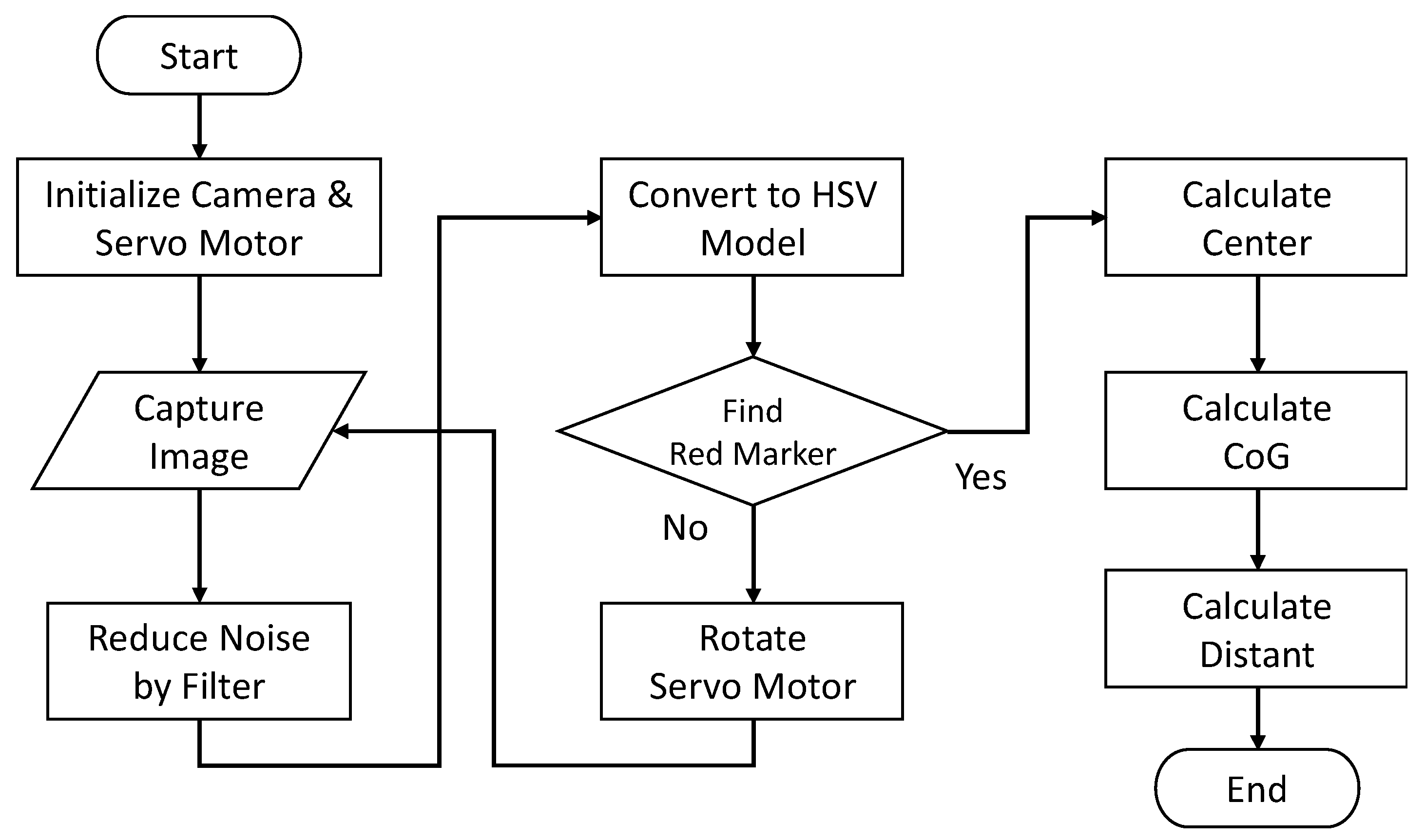
The purpose of the image processing is to have the HR be able to find the TO. Moreover, the HR can obtain the relative orientation from the red masker and then move to the front of the TO. The flowchart of the image processing is illustrated in Figure 3. In the initialization stage, the servo motor would be returned to make the camera face to the front of the HR. Then, the vision system captures an image. This captured image is smoothed with the Gaussian filter to reduce the noise.
In general, the captured image is in 8-bit red-green-blue (RGB) format. The three elements of color image in RGB are all co-related with the amount of light hitting the object. It is hard to separate color information from luminance. In other words, we cannot easily detect the correct color information of the red marker when the luminance of the environment is varying. Therefore, we convert the image format from the RGB model to hue, saturation, and value (HSV) model. “Hue” represents the color, “Saturation” represents the amount with which that respective color is mixed, and “Value” represents the amount of black with which that respective color is mixed. HSV is used to separate image luminance from color information. HSV is more robust external lighting changes. The image processing techniques that are used in this study are implemented by OpenCV and Python on RPi. The kernel dimension of the Gaussian filter is chosen in the practice experiment.
2.3. Orientation Calculating
The vision system further detects whether the red marker is found in the FOV. When the red marker is not found, the SG90 servo motor will rotate a pre-defined angle such that the robot can search for the red marker with a different region until the red marker of the TO is found. Due to the fact that the HR has only a vision sensor to obtain the orientation information of the TO, it is important to find an approach to let the HR move to the front of the TO with the insufficient image information. The captured image is shown as Figure 2b when the HR is standing on the front of the TO. When the TO is in the left front of HR, the view of the HR is shown in Figure 2c. Figure 2d is shown as the TO is in the right front of HR. First, we need to find the corners of the red marker. The center point (the yellow point in Figure 2) and the center of gravity (the blue point in Figure 2) can be calculated using four corner points. Then, we can obtain the orientation information of TO using the relationship between the center point and the center of gravity point (CoG). The center point, , can be calculated as follows
where is the i-th corner coordinate (the red point in Figure 2). The center of gravity, , is calculated in the following
where is the coordinate of the i-th points of the red marker. Therefore, the orientation of the TO in view of HR can be represented as
where is a constant.
2.4. Distance Estimating
As previously mentioned, the sensing ability of HR depends only on the vision system. Besides the orientation, the distance between the HR and the TO, , is another important information. It can be easily seen that HR can lift the TO correctly only when the following condition is satisfied:
where and are constants corresponding with the arm length of the HR, and .
Additionally, the mode of gait pattern of the HR is selected according to the . There are two stages, including the processing of image information and motion control, in the one cycle of the control process. Therefore, the processing time, , in one cycle of the control process can be represented as
where is the time of image processing, is the execution time of completing one gait, and is the idle time and . It is not efficient that the gait is fixed in a fixed due to the limited computational capability of the vision system. Therefore, if the distance is far, , the gait of the HR can execute repeatedly more times such that the period time can be rewritten as
where is a function of to represent the repeat number and the detail of is described in Section 3. Since the size of the marker on the box can be known in advance, we can have the real width, , of the TO. In addition, the distance information can be calculated with the focal length of the camera, ,
To find the , the HR and the TO are placed on a preset position with a known distance, , between the HR and the TO. Then, with the vision camera opened, the width of the TO image can be determined when the distance between HR and TO is fixed at . Since the focal length of the camera is found, the distance of the object to the camera can be calculated as
when the HR starts to move. Although the distance that is obtained by Equation (8) is not precise, it is still necessary and valuable information to have the HR move to the object and satisfy the condition in Equation (4).
3. Cooperative Transportation Strategy
The control strategies of the cooperation transportation system contain three stages, including object TO searching, walking toward the TO, and cooperatively moving the TO. In the first stage, each HR would search for the red marker on the TO and turn to face the TO. In the stage of walking toward the TO, a motion controller is designed to let condition (4) be satisfied. Finally, two HRs would cooperatively move the TO to the destination after the second stage of each HR is completed. Meanwhile, the motion calibration would be triggered to avoid the TO falling when condition (4) is not satisfied in either HR. A flowchart of the control strategy is shown in Figure 4.
3.1. Fuzzy Technique
The motion controllers in various stages are based on fuzzy techniques and two distinct pre-planned gaits. As aforementioned in Section 2.4, the selected gait of the HR can execute repeatedly more times in one cycle of the control process to improve the control performance. Different repeat numbers would be adopted in the different control stages. The repeat number, , is chosen according to the necessary turned angle in the stage of object searching and the repeat number, , is dependent on the distance in stage of walking toward the TO. In this research, the fuzzy technique is utilized to calculate the appropriate repeat number in each stage of motion control.
Consider fuzzy rules as
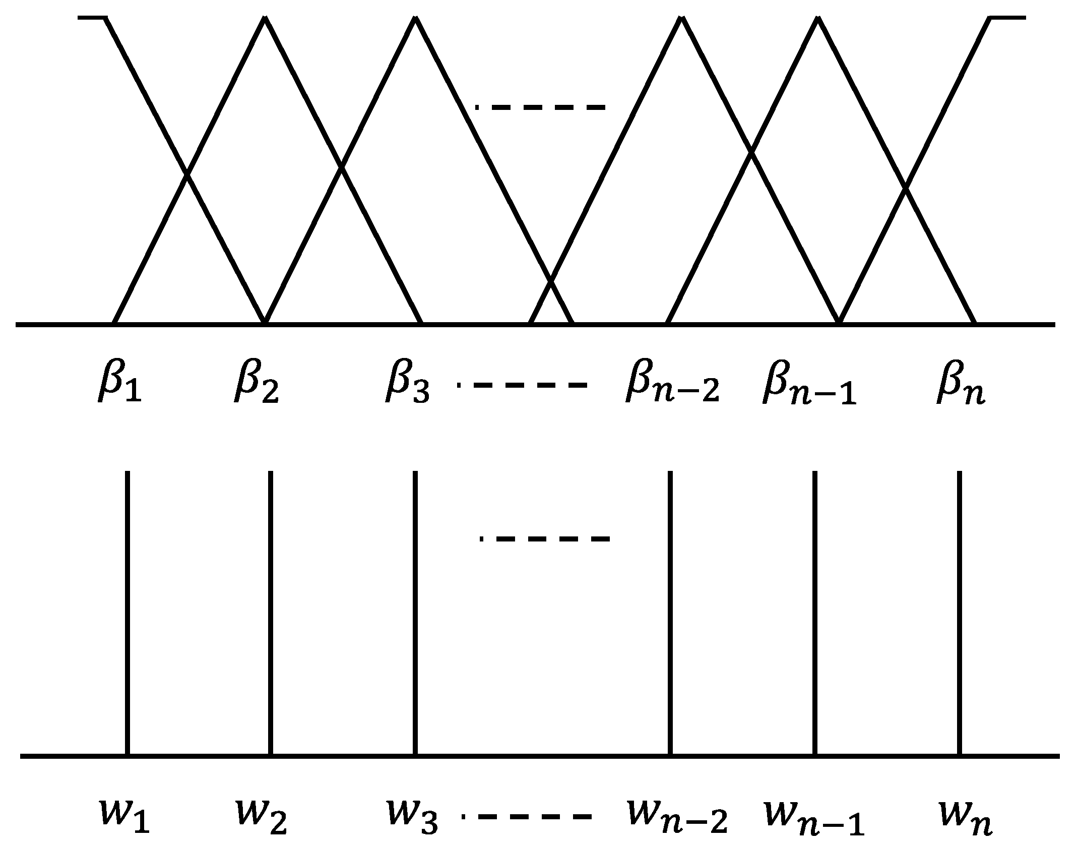
where is the j-th rule, and are the input and output of fuzzy system, respectively. and are the fuzzy sets characterized by fuzzy membership function and , respectively. In this research, the triangular membership functions are selected for and the singleton membership functions are chosen for , shown as Figure 5. By using the centroid defuzzification technique, the output of fuzzy algorithm can be obtained as
As in Figure 5, is the parameters of triangular membership function in the input-part of a fuzzy controller and is the parameters of singleton membership function in the output-part of a fuzzy controller.
3.2. Object Searching
The aim of this stage is to let the red marker be found by the vision system in the FOV. The SG90 servo motor will rotate at a pre-defined angle until the red marker of the TO is found. The accumulative rotating angle of SG90 is saved as when the red marker of the red marker is found. Then, the HR needs to be controlled to turn an angle .
In general, HR cannot turn to the desired angle in one move. We design two different and fixed modes of turning gait, i.e., one of the turning gaits is selected to let the HR have a large variation of turning angle if and another gait is to allow the HR with a small variation if , where is a switching threshold. Based on the fuzzy technique, an algorithm to determine the turning repeat number is designed as follows
and the parameters of fuzzy system are selected as and . The repeat number, , is calculated in the following
The turned direction is left if is negative and right if is positive. The pseudocode of object searching is shown in Algorithm 1.
| Algorithm 1: Algorithm of searching TO. | |
| 1: | Initialization: setting the SG-90 to the home position |
| 2: | if the red market is not in front of FOV then |
| 3: | if the red marker is in the left front of FOV then |
| 4: | The robot should turn left |
| 5: | elseif the red market is in the right front of FOV then |
| 6: | The robot should turn right |
| 7: | else |
| 8: | The robot should turn left |
| 9: | Goto 2 |
| 10: | end |
| 11: | end |
3.3. Moving to Object
To control the HR walking to an object, we designed two different and fixed modes of moving gait, i.e., one of the gaits was selected to let the HR have a large variation of motion if and another gait was to allow the HR a small variation if or , where is a switching threshold. Based on the fuzzy technique, an algorithm of a moving repeat number is designed as follows
and the parameters of a fuzzy system are selected as and . The repeat number, , is calculated in the following
The pseudocode of walking to TO is shown in Algorithm 2.
| Algorithm 2: Algorithm of walking to TO. | |
| 1: | if then |
| 2: | go to the next stage |
| 3: | end |
| 4: | if then |
| 5: | HR go back with small variation gait |
| 6: | elseif then |
| 7: | HR goes forward with small variation gait and repeat |
| 8: | elseif then |
| 9: | HR goes forward with large variation gait and repeat |
| 10: | end |
| 11: | go to the stage of transported object searching |
3.4. Cooperative Transportation and Calibration
In the stage of cooperatively moving the TO, the movements of the two HRs must be synchronized. Therefore, a master–slave system using TCP/IP to communicate through a wireless network is implemented to exchange the movement command between the two cooperative HR. The master HR would transmit a motion request to the slave HR and await the Acknowledge (ACK) from the slave HR. Then, the master HR executes the according motion when the ACK is received. On the other hand, the slave HR would transmit an ACK to the master HR when it receives a request, and it has completed the previous action. After ACK is transmitted, the slave HR would execute the specified motion. In this stage, to complete the task that moves the TO from the starting position to the desired position, the candidate motions contain raising arm, walking sideways, and putting down.
Since the type of HR arm is a tray, not a gripper, the TO might be dropped during transportation. In general, the motion of walking sideways is executed to make not only lateral movement but also slightly turning such that the accumulated turning angle would be increased. The HR moving sideways with the existing turned angle would lead the distance to be increased or decreased such that condition (4) fails. Therefore, the angle of facing the TO needs to be calibrated. The rotating angle of SG90 cannot be utilized to estimate the facing angle because the red marker is always in the FOV, when . To overcome this problem and to estimate the relative orientation between the HR and the TO, the center point and the center of gravity point, which are described in Section 2.3, are adopted to calculate the orientation in Equation (3). The process of calibration would be enabled and the process of moving the TO would be paused, when the condition was not satisfied. Then, the HR would be controlled by the corresponding motion according to Equation (3) until the conditions and were satisfied. The pseudocode of cooperative transportation and calibration is shown in Algorithm 3.
| Algorithm 3: Algorithm of cooperative transportation. | |
| 1: | Awaiting the condition (4) is satisfied in each HR |
| 2: | Lifting TO |
| 3: | whileTO does not arrive the desired position do |
| 4: | if then |
| 5: | repeat |
| 6: | motion calibration |
| 7: | until and |
| 8: | end |
| 9: | HR walking sideways |
| 10: | End |
| 11: | Putting down TO |
4. Experimental Results
Two experiments are presented to validate the effectiveness of the proposed approach in this section. The first scenario is that one HR moves toward the TO with/without the proposed fuzzy motion controller. The second scenario is that two HRs cooperatively transport the TO. Due to the load capacity of HR, a white box, in which its dimension is (L: 320 mm, W: 220 mm, H: 110 mm) and its weight is 200 g, is selected as a TO in each experiment. To facilitate the observation and recording of the experimental results, an additional red marker is placed on the top of the white box, except on both sides. Since the performance of the smart servo motor would be affected by a low battery, the power source of each HR is an external power adapter to guarantee that the supply voltage can be stable in the experiments.
The first experiment aims to compare the response of motion control with and without a fuzzy technique. The experiment results are illustrated in Figure 6 and Figure 7, where Figure 6 and Figure 7 are the snapshots of the HR moving toward the TO without and with a fuzzy technique, respectively. In this experiment, the HR is initially placed approximately 60–80 cm away from the TO. From Figure 6, it is seen that it takes approximately 66 s for the task to be accomplished, with the proposed motion controller without fuzzy technique. However, the lifted box looks a little askew at the end of the experiment. From Figure 7, we can obviously see that it takes only 55 s to precisely lift the TO with the proposed fuzzy motion controller. To verify its reproducibility, the same experiments are repeated ten times. Except the proposed fuzzy motion controller has a shorter execution time; the situation that the lifted box looks a little askew only occurs one time with the proposed fuzzy motion controller but four times using the motion controller without fuzzy technique.
The second experiment is to validate the effectiveness of the proposed fuzzy motion controller for two HRs to cooperatively transport the TO. The configuration of the second experiment is shown in Figure 8, where the white rectangle is the initial location for the TO, the target location of the TO is the gray rectangle. Each black circle represents the HR and the corresponding initial orientation. It is noted that two HRs are placed away on both sides of the box. The initial orientation of HRs is set to have each HR not face the object. Each gray circle represents the target position of each task, respectively. That is, one is the target position for the task to move toward the TO. Another is the target position for the task of moving the TO to its desired position. The dash line is shown as the desired moving trajectories of the two HR. The objective of the experiment is that two HRs cooperatively transport a TO from the initial location to the desired location. The distance between the HR and the TO is approximately 40–60 cm and the distance between the TO and the desired position is also approximately 30–40 cm.
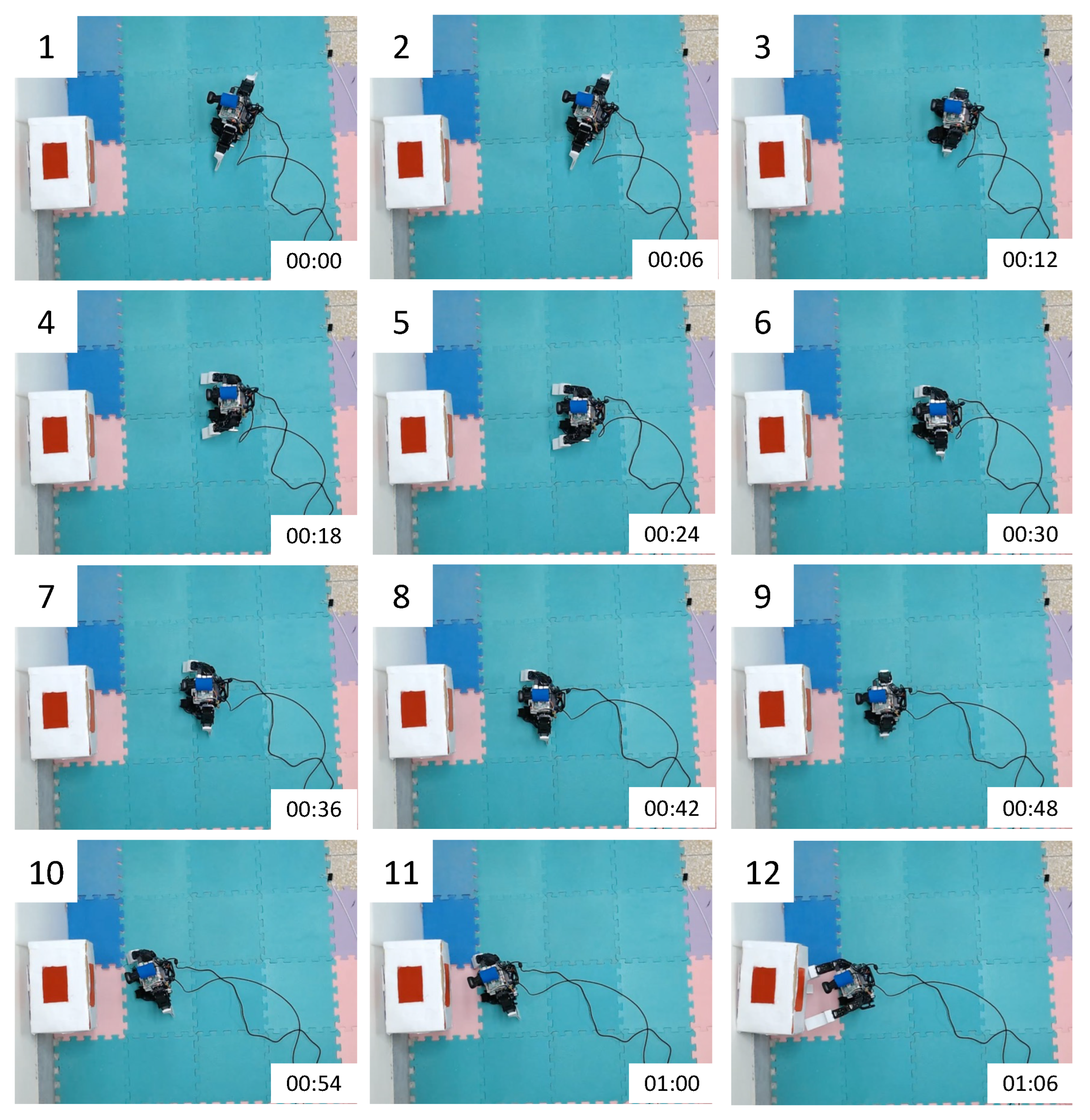
The experimental results are illustrated in Figure 9 (including fourteen subfigures). Two HRs need to cooperatively transport a box to be on top of the white brick in the left. From 1 to 3 in the Figure 9, we can see that two HRs can turn to face box first. Then, each HR moves towards the TO. The HR will lift the TO when distance is smaller than , which is shown in 4 and 6. Figure 7, Figure 8 and Figure 9 show two robots that cooperatively transport an object moving laterally to the desired position. Finally, two HR can put the TO down gently on the white brick, which is shown in 12. Similarly, to verify the experiment’s reproducibility, this experiment is repeated ten times. Both HRs can move to the front of the TO at all times, and HRs can put the TO steadily on the platform at the desired position with a success rate of 0.8; however, HRs can put the TO at the desired position without a platform with a success rate of 0.9.
5. Conclusions
A cooperative transportation system with two humanoid robots has been designed in this paper. A raspberry Pi-based vision system has been developed on each modified commercially available Bolide Y-01 humanoid robot. The motion controllers in various stages are based on fuzzy techniques that are utilized to calculate the appropriate repeat numbers in each stage of the motion control. The proposed fuzzy motion controllers are also successfully implemented on the RPi to complete the transportation tasks. From experimental results, it is noted that each robot can search the TO and then move the TO from the starting position to the destination by the proposed algorithm, using only vision feedback. The proposed method can be applied to the simple and the cheap humanoid robot system to execute the cooperative tasks. In this study, the TO is assumed to be well-known, including its shape, dimension, and suitable grab points. In future work, we will further study how to transport a non-rectangle object, especially without a specific marker to let the proposed biped robot cooperation system to be applied to practical applications.
Author Contributions
Conceptualization, C.-W.C. and C.-W.T.; methodology, C.-W.C. and C.-W.T.; software, C.-W.C.; validation, C.-W.C.; writing—original draft preparation, C.-W.C.; writing—review and editing, C.-W.C. and C.-W.T.; funding acquisition, C.-W.T. All authors have read and agreed to the published version of the manuscript.
Funding
This research was funded by Ministry of Science and Technology of Taiwan grant number 110-2221-E-197-030.
Institutional Review Board Statement
Not applicable.
Informed Consent Statement
Not applicable.
Data Availability Statement
Data are contained within the article.
Conflicts of Interest
The authors declare no conflict of interest.
References
- Queralta, J.P.; Taipalmaa, J.; Pullinen, B.C.; Sarker, V.K.; Gia, T.N.; Tenhunen, H.; Gabbouj, M.; Raitoharju, J.; Westerlund, T. Collaborative Multi-Robot Search and Rescue: Planning, Coordination, Perception, and Active Vision. IEEE Access 2020, 8, 191617–191643. [Google Scholar] [CrossRef]
- Zhang, L.; Sun, Y.; Barth, A.; Ma, O. Decentralized Control of Multi-Robot System in Cooperative Object Transportation Using Deep Reinforcement Learning. IEEE Access 2020, 8, 184109–184119. [Google Scholar] [CrossRef]
- Rasheed, A.A.A.; Abdullah, M.N.; Al-Araji, A.S. A Review of Multi-Agent Mobile Robot Systems Applications. Int. J. Electr. Comput. Eng. 2022, 12, 3517–3529. [Google Scholar]
- Feng, Z.; Hu, G.; Sun, Y.; Soon, J. An Overview of Collaborative Robotic Manipulation in Multi-robot Systems. Annu. Rev. Control 2020, 49, 113–127. [Google Scholar] [CrossRef]
- Zbiss, K.; Kacem, A.; Santillo, M.; Mohammadi, A. Automatic Collision-Free Trajectory Generation for Collaborative Robotic Car-Painting. IEEE Access 2022, 10, 9950–9959. [Google Scholar] [CrossRef]
- Hu, J.; Bhowmick, P.; Lanzon, A. Group Coordinated Control of Networked Mobile Robots with Applications to Object Transportation. IEEE Trans. Veh. Technol. 2021, 70, 8269–8274. [Google Scholar] [CrossRef]
- Chang, Y.-H.; Chang, C.-W.; Chen, C.-L.; Tao, C.-W. Fuzzy Sliding-Mode Formation Control for Multirobot Systems: Design and Implementation. IEEE Trans. Syst. Man Cybern. Part B 2012, 42, 444–457. [Google Scholar] [CrossRef]
- Lytridis, C.; Kaburlasos, V.G.; Pachidis, T.; Manios, M.; Vrochidou, E.; Kalampokas, T.; Chatzistamatis, S. An Overview of Cooperative Robotics in Agriculture. Agronomy 2021, 11, 1818. [Google Scholar] [CrossRef]
- Morar, C.A.; Doroftei, I.A.; Doroftei, I.; Hagan, M.G. Robotic applications on agricultural industry. A Rev. IOP Conf. Ser. Mater. Sci. Eng. 2020, 997, 012081. [Google Scholar] [CrossRef]
- Grigore, L.S.; Priescu, I.; Joita, D.; Oncioiu, I. The Integration of Collaborative Robot Systems and Their Environmental Impacts. Processes 2020, 8, 494. [Google Scholar] [CrossRef] [Green Version]
- Tsai, C.-C.; Hsu, C.-F.; Wu, C.-W.; Tai, F.-C. Cooperative Localization Using Fuzzy DDEIF and Broad Learning System for Uncertain Heterogeneous Omnidirectional Multi-robots. Int. J. Fuzzy Syst. 2019, 21, 2542–2555. [Google Scholar] [CrossRef]
- Joseph, A.; Christian, B.; Abiodun, A.A.; Oyawale, F. A Review on Humanoid Robotics in Healthcare. MATEC Web of Conferences 2018, 153, 02004. [Google Scholar] [CrossRef]
- Rojas-Quintero, J.A.; Rodríguez-Liñán, M.C. A Literature Review of Sensor Heads for Humanoid Robots. Robot. Auton. Syst. 2021, 143, 103834. [Google Scholar] [CrossRef]
- Kuo, P.-H.; Hu, J.; Lin, S.-T. Fuzzy Deep Deterministic Policy Gradient-Based Motion Controller for Humanoid Robot. Int. J. Fuzzy Syst. 2022. [Google Scholar] [CrossRef]
- Kahraman, C.; Deveci, M.; Boltürk, E.; Türk, S. Fuzzy controlled humanoid robots: A literature review. Robot. Auton. Syst. 2020, 134, 103643. [Google Scholar] [CrossRef]
- Angelopoulos, G.; Baras, N.; Dasygenis, M. Secure Autonomous Cloud Brained Humanoid Robot Assisting Rescuers in Hazardous Environments. Electronics 2021, 10, 124. [Google Scholar] [CrossRef]
- Zanlongo, S.A.; Dirksmeier, P.; Long, P.; Padir, T.; Bobadilla, L. Scheduling and Path-Planning for Operator Oversight of Multiple Robots. Robotics 2021, 10, 57. [Google Scholar] [CrossRef]
- Juang, L.H. The Cooperation Modes for Two Humanoid Robots. Int. J. Soc. Robot. 2021, 13, 1613–1623. [Google Scholar] [CrossRef]
- Wang, X.; Zheng, L. Design of Multi-Robot Cooperative Transport System. In Proceedings of the 7th International Conference on Intelligent Computing and Signal Processing (ICSP), Xi’an, China, 15–17 April 2022; pp. 1370–1373. [Google Scholar]
- Zhong, Q.; Li, Y.; Zheng, C.; Shen, T. Humanoid Robot Cooperative Motion Control Based on Optimal Parameterization. Front. Neurorobotics 2021, 15, 699820. [Google Scholar] [CrossRef] [PubMed]
Figure 1.
The diagram of the cooperation transportation system.

Figure 2.
Schematic of the transportation object where (a) is a transportation object, and the view of the robot in (b) the center of box, (c) the right of box, (d) the left of box.
Figure 2.
Schematic of the transportation object where (a) is a transportation object, and the view of the robot in (b) the center of box, (c) the right of box, (d) the left of box.

Figure 3.
Flowchart of the image processing.

Figure 4.
Flowchart of the motion of HR.

Figure 5.
The membership function of fuzzy system.

Figure 6.
Experimental results of one HR without fuzzy technique.

Figure 7.
Experimental results of one HR with fuzzy technique.

Figure 8.
Experimental configuration.

Figure 9.
Experimental results of cooperative transportation.

Publisher’s Note: MDPI stays neutral with regard to jurisdictional claims in published maps and institutional affiliations. |
© 2022 by the authors. Licensee MDPI, Basel, Switzerland. This article is an open access article distributed under the terms and conditions of the Creative Commons Attribution (CC BY) license (https://creativecommons.org/licenses/by/4.0/).
Share and Cite
MDPI and ACS Style
Chang, C.-W.; Tao, C.-W. The Design and the Development of a Biped Robot Cooperation System. Processes 2022, 10, 1350. https://0-doi-org.brum.beds.ac.uk/10.3390/pr10071350
AMA Style
Chang C-W, Tao C-W. The Design and the Development of a Biped Robot Cooperation System. Processes. 2022; 10(7):1350. https://0-doi-org.brum.beds.ac.uk/10.3390/pr10071350
Chicago/Turabian StyleChang, Chia-Wen, and Chin-Wang Tao. 2022. "The Design and the Development of a Biped Robot Cooperation System" Processes 10, no. 7: 1350. https://0-doi-org.brum.beds.ac.uk/10.3390/pr10071350
Note that from the first issue of 2016, this journal uses article numbers instead of page numbers. See further details here.