Article

Device Testing: High-Efficiency and High-Uniformity Microwave Water Treatment System Based on Horn Antennas

1
College of Electronic and Information Engineering, Sichuan University, Chengdu 610065, China
2
College of Computer Science and Cyber Security, Chengdu University of Technology, Chengdu 610065, China
3
College of Electronic Engineering, Chengdu University of Information Technology, Chengdu 610065, China
*
Author to whom correspondence should be addressed.
Submission received: 8 February 2023 / Revised: 2 March 2023 / Accepted: 7 March 2023 / Published: 9 March 2023
(This article belongs to the Special Issue Chemical Process Modelling and Simulation)

Abstract

:
Microwave heating has excellent potential for applications in wastewater treatment. This study proposes a highly efficient continuous liquid-phase microwave heating system to overcome the problems of low treatment capacity, low dynamic range of loads, and insufficient heating uniformity of the existing equipment. First, a quarter-wavelength impedance-matching layer improves heating efficiency, and the heating uniformity has been enhanced by horn antennas. Second, an experimental system is developed. The simulation and experimental results are consistent, with the microwave system achieving over 90% energy utilization for different thicknesses and concentrations of salt water. Finally, simulations are performed to analyze microwave efficiency and heating uniformity at different flow rates, salinities, dielectric properties, and sawtooth structures. The system can efficiently heat loads with a wide range of dielectric properties, including saline water. Generally, when the permittivity varies from 10 to 80, and the loss tangent varies dynamically from 0.15 to 0.6, more than 90% of microwave efficiency and excellent temperature distribution (The coefficient of temperature variation COV < 0.5) can be achieved. The system’s modular design enables scaling up to further boost processing capacity. Overall, the system provides high-throughput, high-efficiency, high-uniformity, and large-dynamic-range microwave water treatment, which has promising applications in industrial water treatment.

1. Introduction

With the advantages of green, clean, fast, efficient, and timely heating [1,2,3], microwave heating technology has exhibited great potential in wastewater treatment. Examples include the treatment of strongly alkaline and acidic wastewater [4,5], waste permeate [6], sewage sludge [7,8], high-salt wastewater [9], and others. Compared to conventional biochemical treatment methods, microwave water treatment is free from secondary and membrane contamination [10], has lower investment and operating costs [11], and results in gentler operating conditions [12]. Microwave water treatment can generate additional energy by-products [13,14]. Existing microwave-based improvements in water treatment equipment and methods have enhanced performance. Bi et al. utilized a microwave-catalyzed ClO2 process to treat phenol wastewater, and the COD (chemical oxygen demand) and phenol removal rates increased by 15.6 and 18.7%, respectively, compared to the conventional scheme. The microwave-induced ClO2 catalytic oxidation system could significantly improve the degradation efficiency [15]. However, the method incurs high operating costs and has unstable catalytic activity. The first simultaneous removal of Cr(VI) and PNP using a non-electric microwave atmospheric pressure plasma jet by Zhao et al. showed that the removal of Cr(VI) and PNP from a mixed solution was 96.1% and 94.0%, respectively, which provided a rapid and efficient single-step treatment of wastewater contaminated with organic pollutants and heavy metals [16]. Liu et al. used an oven intermittently irradiated dye-contaminated wastewater and showed that methylene blue (MB) conversion was as high as 93% after just one minute, which is equivalent to the conventional Fenton method achieved in 65 min [17]. Moreover, Li et al. constructed an MW-enhanced Fenton system using a microwave oven, and compared it to the Fenton process, the Bisphenol A (BPA) removal efficiency increased from 93% to 99.7% and the rate constant increased from 0.87 to 4.67, with microwave intervention facilitating much higher reagent utilization [18]. Based on the existing literature, it can be concluded that most related studies have focused on static water treatment, and there is a lack of devices that can efficiently treat continuous streams. In fact, most of the devices are based on household microwave/oven modifications or are limited to a laboratory setting [19] and may not be adaptable to large-scale treatment volume scenarios in the industry. More importantly, heating uniformity and energy efficiency are two major issues that limit the development and application of microwave heating technology [20].
In liquid-phase microwave heating, uneven heating can result in unstable product quality, thermal runaway, and hot spots [21,22]. Many scholars have attempted to overcome the problem of non-uniformity. Zhao et al. modified glass using the concept of cut-off waveguides, which improves the electric field distribution in the upper and lower layers and promotes natural convection to enhance the transfer of heat. On using this approach of heating in the oven, the temperature difference between the top and bottom of the water reduced from 7.8 °C to 0.5 °C [23]. Rakesh et al. successfully improved the temperature distribution by combining microwave, convection, and radiation heating [24]. Zhao et al. added bubbles to microwave reactors to enhance the flow and improve temperature uniformity [25]. However, the above methods have the problems of static stream processing and low throughput. The throughput can be increased using large-size, high-grade continuous-mode reactors. The establishment of continuous flow piping systems has become a widely accepted measure, as it not only improves the temperature distribution but also facilitates the concentration of microwave energy. Cuccurullo et al. constructed a straight tube structure to provide a high uniformity of heating for low-viscosity Newtonian liquids [26]. Spiral tubes have better heat transfer characteristics than straight tubes because it promotes secondary flow. Zhang et al. obtained an excellent heating performance by adjusting the geometrical parameters of the spiral tube (PCD, diameter, and pitch of the spiral tube) [27]. However, the heating characteristics are sensitive to the load characteristics. Ye et al. developed a microwave heating system for biodiesel synthesis based on a pipe and propeller structure and demonstrated that the heating performance could be improved by adjusting the blade width and propeller pitch [21]. Large-sized machines are also often used; for example, multimode applicators with stirrers and rotating turntables are suitable for pasteurizing large quantities of milk [28], Lin et al. treated sludge with horizontal microwave continuous pyrolysis equipment with a horizontal feed function, effectively increasing biogas production (50.15 wt%) [29], and Shi et al. proposed a coaxial probe microwave reactor beyond the laboratory scale, with an increased number of microwave probes effectively improving heating efficiency, but prone to uncontrolled hot spots [30]. Generally, these methods have a small dynamic range of loads, that is the performance of the reactor is sensitive to the load properties.
There have also been many studies on microwave efficiency. Microwave energy utilization and industrial operating costs are closely related. Triple tuners are the most widely employed method for improving microwave efficiency and exhibits suitable promise for industrial impedance-matching applications [31]. However, the matching algorithm is cumbersome and requires further optimization. Recently, the application of metamaterials has also achieved suitable results in improving microwave efficiency. Wang et al. optimized microwave heating efficiency by configuring the content of wave-absorbing materials [32]. The synthesis of Ag-coated Fe (Fe@Ag) core-shell nanowires, which significantly improved impedance matching, demonstrated excellent microwave absorption performance over a wide range of frequency bands [33]. Metamaterials designed based on the black hole theory can achieve efficient microwave absorption in scenarios where the loading parameters vary within a certain range [3]. However, the limitations of the manufacturing process result in non-ideal materials being processed, causing interference with the performance of the methods described above. Lee et al. developed a new model for liquid heating under simultaneous microwave (MW) and ultrasound (US) irradiation, which increased the liquid flow and heat transfer, thereby improving the efficiency and uniformity of microwave heating [34]. However, the mechanism by which ultrasound improves heating efficiency is unknown and there are additional uncertainties in applying it to industrial wastewater treatment. Gentry et al. improved the efficiency of microwave heating in a continuous flow pasteurization system by designing process parameters, such as input power, volume, load size, and volume flow rate [35];however their method is only valid for specific loads. Most of these studies have focused on improving the heating efficiency at specific loads and are highly dependent on the dielectric load properties. The permittivity of wastewater changes dynamically during heating owing to impurities, salinity, purity, bubbles, temperature, etc. [36]. Therefore, it is urgent to propose a microwave heating system that is not sensitive to loads and can efficiently heat various loads.
The aim of this study is to propose a novel continuous flow microwave water treatment system, which offers the advantages of high efficiency, high-temperature uniformity, large throughput, and a wide dynamic range of loads. The structure of the microwave system is designed in the simulation software, which consists of quarter-wavelength matching layer and horn antennas. A physical model was processed to verify the simulation results. In addition, sensitivity analysis was performed in the simulation software. Microwave efficiency and heating uniformity were tested for different cases (salinity, height, flow rate, dielectric properties, sawtooth structure and comparison with multiple cavities). Overall, the system can efficiently heat different loads with large-dynamic-range dielectric constants.

2. Materials and Methods

2.1. Geometry Model

Figure 1 illustrates the geometric model created using COMSOL Multiphysics (COMSOL Inc., Stockholm, Sweden). The simulation model consists of four parts, four BJ-22 waveguides (height h = 100 mm) for microwave power input, four horn cavities, a quarter-wavelength impedance-matching layer (length(w1) = 16.38 cm, width (b1) = 8.19 cm, thickness (t) = 1 cm), and a double-ended open cavity (length (w2) = 33.76 cm, width (b2) = 17.38 cm, and height (wh) = 3 cm) for passing continuous flow.
With a horn cavity height (hw) of 120 mm and a 5° tilt at the top and bottom ports, the electric field is evenly distributed in the direction of the center of the wide side of the horn antenna parallel to the narrow side, which uniformly heats the liquid flowing overhead. The impedance-matching layer is designed for the water load so that electromagnetic waves can be radiated to the upper medium with little reflection. To further improve the uniformity and efficiency of heating, a sawtooth structure can be added to the water layer, which is discussed in a later section.

2.2. Simulation Settings and Governing Equations

In this study, the electromagnetic wave frequency was set at 2.45 GHz, which is a freely licensed ISM frequency defined by the International Telecommunication Union (ITU) and is widely utilized in the industry. One side of the waveguide was a rectangular excitation port, from which 1 kW of the electromagnetic wave was fed. The waveguide and cavity walls were set up as perfect electrical conductors (PEC), and electromagnetic waves propagated along the cavity with a single mode of TM10. Following transmission to the water-loading layer, electromagnetic energy is absorbed and converted to heat.
The electromagnetic module follows Maxwell’s equations:
× H = J + ε E t
× E = B t
· B = 0
· D = ρ e
where E denotes the electric field strength (V/m), H indicates the magnetic field strength (A/m), B denotes the magnetic induction strength (Wb/m2), D signifies the potential shift vector (C/m2), J corresponds to the current density (A/m2), ε symbolizes the relative permittivity (F/m), and ρe denotes the charge density (C/m3).
The electromagnetic energy loss in the system is expressed as
Q e = 1 2 ω ε 0 ε | E | 2
where Qe denotes the electromagnetic power loss (W) and ε″ symbolizes the imaginary part of the complex dielectric constant. From the law of conservation of energy, this energy is used as the heat source for heating the liquid load according to the following relationship:
Q e = ρ C p T t k 2 T
where T denotes the temperature (K), Qe represents the heat source, ρ symbolizes the density of the material (kg/m3), Cp refers to the constant pressure heat capacity (J/(kg·K)), and k represents the thermal conductivity (W/(m·K)). The initial temperature T0 was set to 293.15 K.
Furthermore, the flow of the liquid-phase layer in this system should satisfy the Navier–Stokes equations, and the laminar flow module must satisfy the following continuity conditions:
ρ u / t + ρ ( u ) u = [ p I + μ ( u + ( u ) T ) 2 / 3 μ ( u ) I ]
ρ u = 0
Here, u denotes the fluid velocity (m/s), ρ symbolizes the fluid density ((kg/m3), μ denotes the hydrodynamic viscosity (Pa · s), and I represents the unit matrix.
In COMSOL simulations, the electromagnetic field was calculated using the RF module with the PARDISO Direct Solver. Continuous flow and heat transfer were solved using the laminar flow module. Unidirectional coupled electromagnetic heat and non-isothermal flows were selected for the multiphysics field. The study steps are as follows: steady-state laminar flow, frequency-domain electromagnetic waves, transient fluid heat transfer, and electromagnetic heat. A fully coupled solution method using the MUMPS direct solver was utilized. The heating time is 20 s. Because the heating time is short, the change in the dielectric constant and other parameters can be neglected.

2.3. Horn Antenna

Horn antennas are surface antennas with the advantages of high gain, wide bandwidth, and high power capacity. The circular or rectangular cross-section of its waveguide terminals gradually expands, which improves the matching between the waveguide and free space, allowing most of the electromagnetic energy transmitted in the waveguide to be radiated. The figures below show the radiation direction diagram and the electric field distribution in the cross-section of the horn antenna designed in this study.
From the directional diagram (Figure 2), it can be seen that the horn antenna has suitable directionality, and the energy is concentrated in the main flap part with a gain of approximately 26.9 dB. Figure 3 shows that the horn antenna improved the microwave energy distribution. At the center of the wide edge of the horn, the electric field energy is high and evenly distributed in the direction parallel to the narrow edge, thus heating the flowing liquid load more evenly and improving the temperature uniformity of heating.

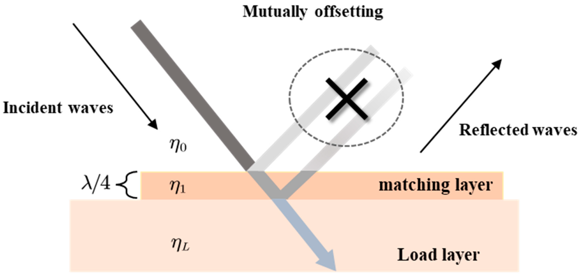
2.4. Quarter-Wavelength Matching Layers

Generally, adding an impedance-matching network between two media can increase microwave energy absorption at the load side and reduce unwanted reflections, which improves the microwave efficiency. The quarter-wavelength has a suitable matching performance near the center frequency. In Figure 4, η0 represents the wave impedance of the lower medium, ηL represents the wave impedance of the load, and η1 represents the wave impedance of the medium introduced for the length of the quarter-wavelength. The matching equation is as follows:
η 1 = η 0 η L
The equipment used in this study, ηL and η0, represent the wave impedances of water load and air, respectively. The wave impedance expression is given in Equation (9), and it is known as εwater = 78 and ε0 = 1. Combined with the matching equation, we can obtain the dielectric constant of the matching layer as ε 1 = ε water ε 0 = 9 .
Matching layer thickness l = λ/4, where λ indicates the phase wavelength, which is calculated as
λ = λ 0 ε r μ r
It is known that μr = 1, εr = 9. Moreover, λ0 denotes the operating wavelength of an electromagnetic wave with a frequency of 2.45 GHz. The calculation yields l ≈ 1.02 cm. Quarter impedance matching was achieved in actual machined experimental equipment using a 1 cm thick ceramic plate. The efficiency of the microwaves radiated from the horn antenna can be improved by introducing an impedance-matching layer, allowing the upper water load to absorb more microwave energy, thus improving energy utilization.

2.5. Boundary Conditions

Corresponding physics boundary conditions are required to solve the computed model. In the EMF module, all surfaces of the model, except for the ports, are defined as perfect electrical conductors to simulate the actual machined metal surfaces. The governing equations for perfect electrical conductors can be expressed as
n × E = 0
where n denotes the unit normal vector of the corresponding surface.
Electromagnetic waves enter the cavity from the four ports in mode TE10 and are absorbed and converted into heat energy after radiation to the topmost layer. During the simulation, the heat was transferred only within the heated material. The thermal boundary between the water layer and the inner wall was set as an insulating boundary condition:
n · q = 0
Here, q denotes the heat flux and n represents the unit vector.
For laminar flow boundaries, set the no-slip boundary conditions as u = 0. The relative velocity of fluid and boundary is zero. The pressure at the outlet of the unit was set to zero, which means that there is no resistance at the outlet [37].

2.6. Experimental System

The experimental system and corresponding equipment were machined, as shown in Figure 5. The horn and housing of the device were composed of aluminum oxide (Chengdu Maipin Power Technology Company Ltd., Chengdu, China). The uppermost layer was used to contain the liquid load, and the top two ends of the layer include the inlet and outlet ports for passing a continuous flow of liquid. The quarter-wavelength matching layer is composed of an alumina ceramic plate with a dielectric constant equal to approximately nine, which is appropriate for the impedance-matching requirement. Other equipment used to complete the experiments include four magnetrons with corresponding cooling fans, a standard BJ22 size waveguide coaxial adapter and corresponding cables (Chengdu Maiping Power Technology Company Ltd., Chengdu, China), and a microwave network analyzer (E83363c, Agilent Technologies, Inc., Wood Dale, IL, USA). The fan (AVC 2B12038B24H) was mounted on one side of the magnetron (Panasonic 2M244-M1, Panasonic, Kadoma, Japan) and driven by four motors for heat dissipation. The microwave power supply was an industrial digital inverter microwave power supply (WepeX1280A) (Shenzhen Magmeet Electric Co., Shenzhen, China), which produced microwaves at a frequency of 2.45 GHz. By injecting the uppermost load cavity with different thicknesses of the liquid layer, the microwave reflection coefficient can be measured directly using a vector network analyzer; thus, the microwave energy utilization can be calculated.
Due to the limitation that the experimental device is not convenient for temperature measurement, the experiment was carried out only in the low-signal mode, with no appreciable heating of water. The maximum output power of the vector network analyzer test port is +24 dBm.

3. Results

3.1. Experimental Validation

This section combines simulation and experiments to verify the microwave utilization of the device under various conditions. Specifically, the microwave absorption rate of highly saline wastewater was investigated at different flow rates and concentrations. The energy efficiency (EE) is equivalent to the microwave absorption rate, which can be calculated from the reflection coefficient S11:
S 11 = 10 lg ( 1 E E )
Numerical simulations were performed using the finite element method in COMSOL (COMSOL Inc., Stockholm, Sweden). The boundary conditions and calculation settings are presented in Section 2, and the material parameters used are listed in Table 1. The reflectance coefficients S11 were obtained for different concentrations of saline at different water layer thicknesses. In the physical experiments, deionized water and analytically pure sodium chloride crystals (Chengdu Changlian Chemical Reagent Co. Ltd., Chengdu, China) were mixed in different proportions to simulate different concentrations of high-salt wastewater. Room temperature conditions were configured with 0% saline, 1% saline, 2% saline, and 3% saline (0% means the test material is deionized water). S11 at different water heights were measured using a microwave network analyzer and compared with the simulation results.
As shown in Figure 6, the simulation and physical experimental results were generally consistent. The liquid thickness affects the reflection coefficient; the thicker the water layer, the smaller the reflection coefficient and the higher the energy utilization. The addition of salt significantly improved microwave efficiency, with saline outperforming deionized water in all cases. The microwave efficiency of saltwater in the simulation exceeded 99% (S11 <−20 dB). In the experiments, the S11 of various concentrations of salt water is less than −10 dB, which is higher than 90% of the energy absorption. When the concentration of saline reaches 2% and 3%, the average energy utilization is over 95%. Furthermore, once the liquid thickness reaches 2 cm or more, the microwave absorption is very high (>99%) and no longer seems to be influenced by the properties of the load, at which point the simulation and experimental results are in suitable agreement.
Based on the above experimental verification, we conclude that the device proposed in this study can achieve efficient microwave water treatment for different liquid heights and brine concentrations, with energy efficiencies greater than 90%. In particular, a higher microwave efficiency (99%) can be achieved with large treatment volumes (increasing the liquid height). Furthermore, the device is more efficient than normal water loading in the treatment of saline water and may exhibit excellent performance in high-salt wastewater treatment.

3.2. Sensitivity Analysis

The coefficient of temperature variation (COV) is used as a measure of the uniformity of the temperature distribution; the higher the value, the less uniform the temperature distribution. It was calculated by dividing the standard deviation of the temperature rises at each position of the sample by the average temperature rise at each position. The COV expression is as follows [40]:
C O V = ( T i T a ) 2 n / ( T a T 0 )
where Ti and Ta are the point and average temperatures of the selected area, and Ta denotes the average temperature of the selected area. n indicates the total number of selected points, and T0 is the initial average temperature.
Because the device proposed in this study is for a continuous fluid, the temperature of the outflow surface is used to calculate the uniformity of heating. Several factors were considered that could affect the heating uniformity of the device, such as the flow rate and height of the fluid, dielectric properties of the fluid, and sawtooth structure. The sensitivity of the device was tested by varying these variables.

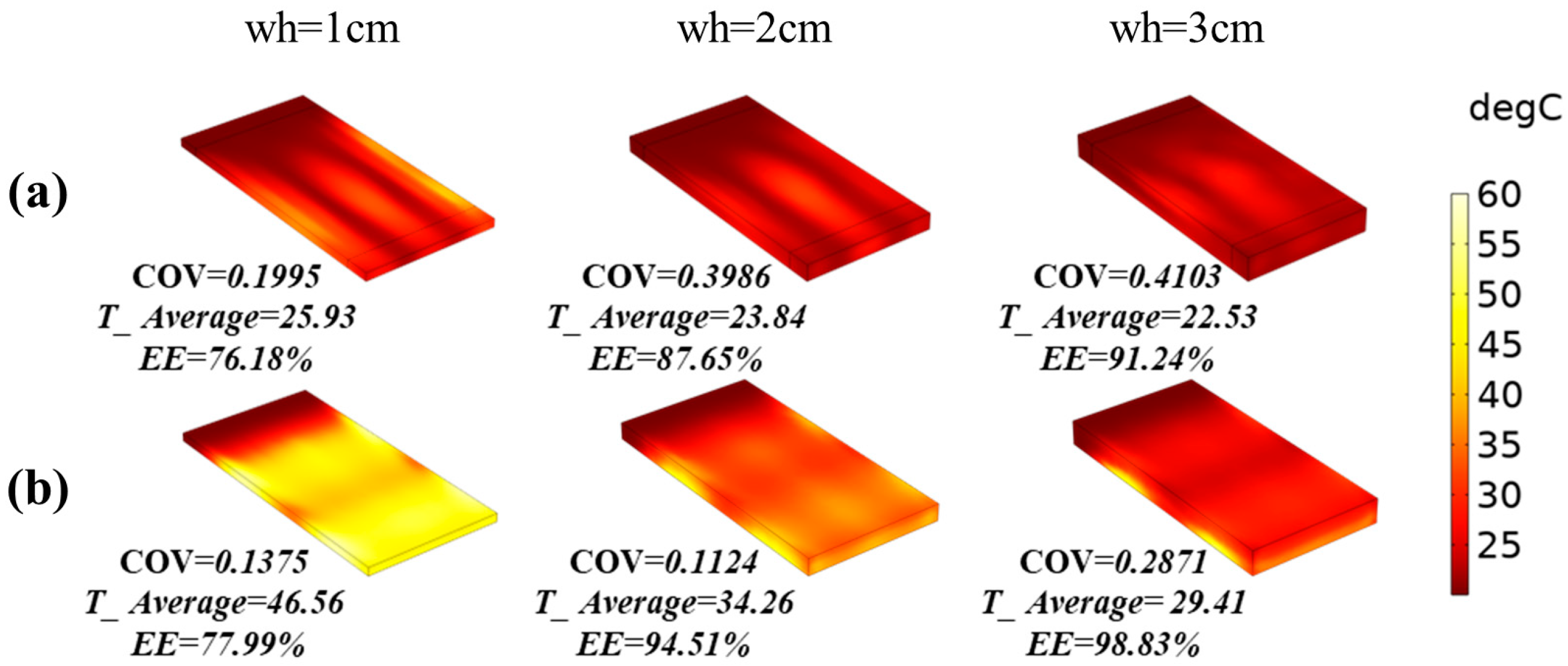
3.2.1. Effect of Fluid Velocity and Height on Heating Uniformity

Figure 7 illustrates the temperature distribution and uniformity at different flow rates and heights. In the practical application of wastewater treatment equipment, velocities of 10 cm/s and 1 cm/s can represent fast and slow flow rates [41,42]. When the height is fixed, the smoother the velocity, the better the temperature uniformity of the outflow section. Similarly, with a fixed velocity, the lower the height, the better the heating uniformity. This indicated that the temperature uniformity of the outflow surface improved as the flow rate decreased. Here, the state with the optimum temperature distribution (COV = 0.1124) did not exactly correspond to the moment of minimum water flow (wh = 1 cm, v = 1 cm/s). This is probably because the microwave energy is fixed, and the water height is so small that the reflection coefficient increases; thus, the thermal energy converted is reduced. Another point that can be observed from Figure 7 is that the average COV value is 0.2647, and the overall heating performance was stable and did not deteriorate sharply as the flow rate increased. The worst case in the results also performed well with COV = 0.4265.

3.2.2. Effects of Saline Water on Heating Uniformity and Electric Field Distribution

In Section 3.1, owing to the inconvenience of measuring the temperature uniformity, only the reflection coefficient (S11) was measured in the experimental section. In this subsection, we use simulations to discuss the heating uniformity of different concentrations of salt water and its electric field distribution. The boundary conditions and control equations were the same as before, and the continuous flow inlet velocity was fixed at 1.5 cm/s. In Figure 8, the reflection coefficient decreases as the water layer thickness increase for a fixed constant brine concentration (consistent with the results shown in Figure 6). The energy efficiency was maintained at over 90% for all statuses. This illustrates that although the matching layer in the device is impedance-matched for pure water, it is also valid for different brines, even if their dielectric properties have changed relative to pure water. In addition, as noted later in the discussion, the microwave efficiency of the device can reach up to 90%, even when the load dielectric constant varies over a certain dynamic range.
For heating uniformity, the smaller the height of the brine, the easier it was to obtain an excellent temperature distribution state (COV < 0.1). From Figure 8, it can be observed that the heating uniformity decreases with increasing salinity when the thickness of the water layer is fixed. This indicates that high salinity affects the heating homogeneity of the equipment and weakens water treatment performance. For example, 3% brine at the height of 3 cm has a COV of 0.7134, at which point the temperature distribution was significantly worse than that of 1% brine at 0.2346. The most effective way to combat this degradation is to reduce the liquid flow rate slightly. As can be seen in the last column of Figure 8, the COV changes from 0.7134 to 0.4012 when the brine concentration was fixed at 3% (at this point, it is considered high salinity and reaches seawater levels [43]) and the height is reduced from 3 to 2 cm, improving the temperature distribution uniformity by 43.76%. Although the optimum temperature distribution (COV = 0.0388) was not achieved at wh = 1 cm, it ensured that the treatment volume was not too small. In practical production applications for low-salinity wastewater (concentrations of approximately 0.5–2%), our equipment easily achieves high energy efficiency and high-temperature uniformity in microwave water treatment. Even in the case of highly saline wastewater treatment, the appropriate flow rate (height and speed) can be adjusted based on the required outlet temperature and uniformity. This demonstrates the robustness of the device proposed in this study, which can ensure both high uniformity of microwave heating and the maintenance of a large treatment capacity.

3.2.3. Effects of Load’s Dielectric Properties on Heating Performance

It is necessary to investigate the performances of our system under different dielectric loads. The simulation was set up as before (v = 1.5 cm/s, wh = 1 cm), and two cases were simulated and calculated. In the first case, the loss angle tangent value of 0.15 is kept constant, and the real part of the dielectric constant varies in the range of 10–80; in the second case, the real part of the dielectric constant was fixed at 80, and the loss tangent value varies in the range 0.15–0.6.
Figure 9 illustrates the S11 and COV curves for different liquid thicknesses as the real part of the dielectric constant was varied. As the real part gradually increases, the reflection coefficients corresponding to different heights exhibit a trend of decreasing and then increasing. When the real part of the complex dielectric constant is greater than 20, the reflection coefficient S11 is less than −10 dB, which is greater than 90% of the microwave efficiency, except in the case of 1 cm and 1.5 cm water height. When the real part ranges from about 20–50, the microwave efficiency corresponding to 1 cm height is also higher than 90%. When the real part of the dielectric is greater than 30, the microwave efficiency of 1.5 cm liquid height is stable above 90%. However, increasing the real part of the dielectric constant can increase the heating uniformity and improve the temperature distribution of the outflow cross-section. The right panel of Figure 9 illustrates that the COV is generally less than 0.5, with the COV value gradually decreasing as the dielectric real part increases. When the liquid height is less than 2 cm, COV < 0.3. Figure 10 illustrates the S11 and COV curves corresponding to different liquid thicknesses as the loss tangent varies. The average reflection coefficient S11 < −20 dB at each height, except for the case of wh = 1 cm; that is, the microwave efficiency was high at different loss angles, exceeding 99%. As the loss tangent increases, the COV increases; that is, the temperature distribution uniformity is affected; however, overall COV < 0.55 is satisfied, and the heating uniformity of the microwave system is suitable. It is worth mentioning that the case of increasing loss tangent covers the previous discussion on the relationship with different concentrations of salt water (Figure 6, Figure 8), as the salinity of the water primarily affects the imaginary part of the complex dielectric constant [44]. In conclusion, excluding extreme cases (extremely low load height, reduce the dielectric real part, or loss tangent too large), the proposed device can ensure stable heating efficiency (COV < 0.5) and high microwave absorption (S11 < −10 dB). The performance of the heating system is insensitive to loads and has a large dynamic range of dielectric properties.

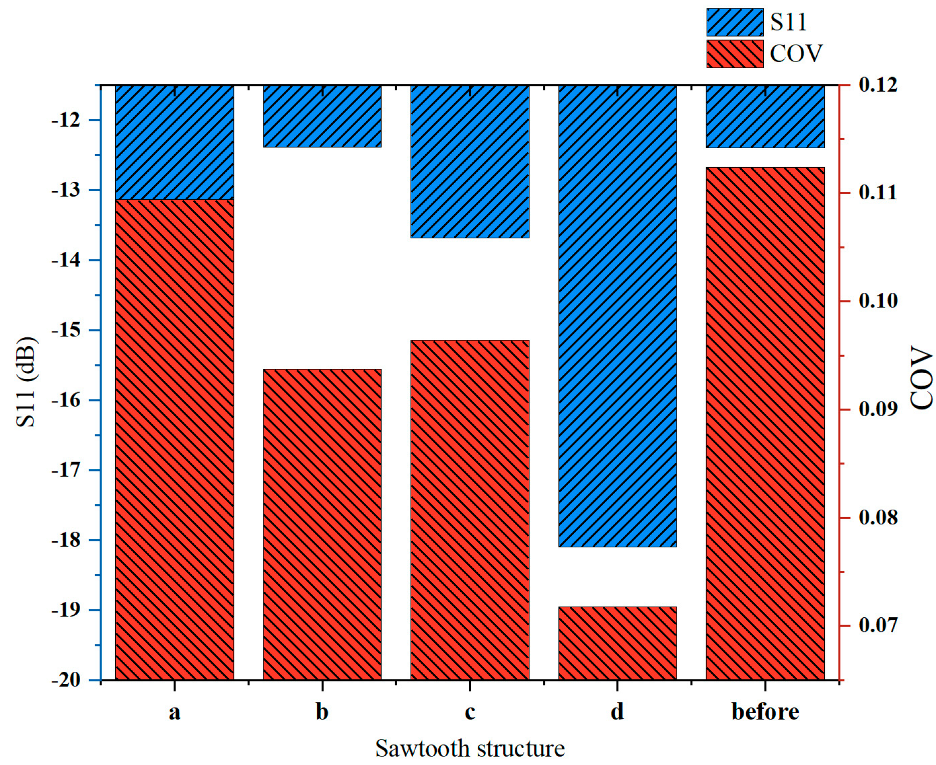
3.2.4. Effect of Sawtooth Structure on the Heating Uniformity

The design of the sawtooth structure or undulating structure in the uppermost layer of the device could help increase the radiation area of microwaves and promote more uniform and effective absorption of microwaves, thus improving the heating uniformity. The following numerical simulations were performed to verify this conclusion: Several different sawtooth structures were designed (Figure 11) with the following structural parameters: (a) bar sawtooth, 3 × 5, length-width-height 1 cm × 8 cm × 3 cm; (b) conical sawtooth, 4 × 6, bottom radius 1.5 cm, height 2 cm; and (c) block sawtooth, 5 × 10, length-width-high 1 cm × 1 cm × 3 cm. (d) spherical sawtooth (hemispherical), 4 × 6, radius 1 cm. Keeping the flow rate 0.1 m/s and the height of the liquid layer at 2 cm, other settings, and boundary conditions were kept the same as before, and the microwave heating and microwave efficiency were analyzed using COMSOL (Figure 12).
From Figure 13, it is evident that all the schemes except the strip serration (Scheme a) help improve the temperature uniformity; schemes c and d are particularly obvious, and the COV values are reduced from the original 0.1124 to 0.0952/0.0718, respectively, while the S11 parameters are reduced from the original −12.4 dB to −13.69 dB and −18.10 dB, respectively, and the microwave efficiency is higher than 95%. Based on these findings, it is concluded that the design of the sawtooth structure/undulating structure improves energy utilization and uniformity, which is helpful for increasing the performance of the device. In particular, the hemispherical structure (Scheme d) is the best, as it allows a 36.12% reduction in COV, a 31.4% increase in microwave efficiency, and the highest average temperature, as shown in Figure 11.

3.2.5. Compared to Conventional Multimode Cavity

The proposed heating system is compared with a conventional multimode heating cavity under different loading conditions (multimode heating cavity model from COMSOL case library, application ID: 1424). The multimode heating cavity is a conventional microwave oven with the geometry shown in Figure 14. The dimensions of the heated object in both systems were set identically at 327.6 mm × 163.8 mm × 2 mm. a continuous flow load was applied through the microwave oven at a distance of 21 mm from the bottom, and the speed was set at 1 cm/s. The microwave power was 1000 W, the initial temperature was 293.15 K, the microwave frequency was 2.45 GHz, and the heating time was 20 s.
First, the real part of the dielectric constant of the heated object was modeled as 80, with a loss tangent between 0.15 and 0.6. The reflection coefficients were calculated for different cases (Figure 15a). Next, the loss angle of the object being heated was kept at 0.15, and the relative permittivity was varied in the range of 10–80 to calculate the reflection coefficient (Figure 15b). The effect of the mean temperature on relative permittivity is ignored in the simulation. The reflection coefficient is indicative of the microwave energy utilization and is used to describe the heating efficiency. As shown in Figure 15, when the load loss angle is in the range of 0.15–0.6, the reflection coefficient of our proposed system is reduced by an average of 12.6 dB compared to a multimode cavity, which is an improvement in the energy efficiency of 94.5% approximately. When the real part of the relative dielectric constant is varied from 10 to 80, the energy efficiency is improved by 71.2% on average. In addition, in Figure 16, we can also find that the heating uniformity of our proposed system is better than that of the multimode cavity at different treatment volumes. In particular, the heating uniformity improves significantly when the water layer height wh = 2 cm, by about 254.62%. Overall, our system has a more stable heating efficiency for different loads.

3.2.6. Scale-Up

To enable larger-scale microwave water treatment, the suggested system can be expanded by connecting in a variety of ways. The increase in treatment capacity was achieved by expanding the number of horn antennas without compromising efficiency and temperature uniformity (Figure 17). In the simulation, the load was still water, the water velocity was set to 1 cm/s, the height was 1 cm, and the other boundary conditions were set as before. The microwave power at each horn antenna port was 1 kW, and the initial temperature of the inflow surface was 293.15 K.
As shown in Figure 17, enlarging the horn array has not affected the heating efficiency and has greatly increased the real-time throughput. The 2 × 2, 3 × 3, 4 × 4 array of horn antennas processes 1.073 L/s, 2.414 L/s, and 4.293 L/s of water per second, respectively. Another advantage of the system can be seen here: the modular design allows for flexible configuration, splicing, and expansion according to the needs of any water flow, with a high degree of reconfigurability. High-throughput, high-efficiency, high-uniformity, and high-dynamic-range microwave water treatment have become possible.
When multiple microwave sources are present, there may be a coherence problem, which requires additional discussion. We calculated the data for S21, S31, and S41 at different water layer heights in our simulation (Figure 18). As can be seen from the graph: S21, S31, and S41 are below −20 dB, or even less, which means that the energy transmitted from one port input to other ports is only less than 1%. It is concluded that the mutual coupling between multiple microwave sources is so small that it can be neglected; therefore, we consider the sources to be incoherent.

4. Conclusions

In this study, a new microwave water treatment system that enables continuous flow heating with high efficiency and high-temperature uniformity was developed. The proposed system uses a quarter-wavelength matched layer to enhance microwave absorption and a uniform electric field distribution at the center of the broadside of the horn antenna to improve heating uniformity. Experiments have proved that the system has the advantage of high throughput and a large dynamic range of dielectric properties. First, the energy utilization of the proposed system is higher than 90% when the water height is 1–3 cm, and the brine concentration is 1–3%. At the same time, excellent heating uniformity (COV < 0.1) can be obtained. Second, by varying the flow rate and height of the liquid, the COV value will not exceed 0.5. Energy utilization is above 90% with a height of more than 1 cm. Third, the heating performance is insensitive to the load properties. Simulations show that the average energy utilization is above 90%, and the temperature uniformity is excellent when both the real and imaginary parts of the relative dielectric constant are varied. Fourth, a comparison is made with conventional multimode heating cavities. The results show that when the loss tangent of the relative dielectric constant ranges from 0.15 to 0.6, the average microwave heating efficiency of the proposed system is approximately 94.5% higher than the conventional microwave heating system. Fifth, the introduction of a sawtooth structure can enhance the heating uniformity, such that the COV increases by approximately 30% while ensuring high energy utilization. Additionally, the system adopts a modular design, allowing for flexible expansion of the processing capacity.
This study further demonstrates that the designed microwave water treatment system has promising applications in the treatment of saline wastewater. This occurs because, as demonstrated by studies and simulators, an increase in salt concentration leads to a rise in dielectric loss, which significantly improves microwave absorption. Depending on the actual requirements, the liquid flow can be modified to provide the optimum temperature distribution. This study has significance for both the science of wastewater treatment and the building of large-scale, highly effective industrial water treatment plants.

Author Contributions

Conceptualization, Methodology, Funding acquisition, H.Z.; Software, Data curation, Visualization, Writing original draft preparation, R.T. and F.Y.; Data curation, Validation, Investigation, Y.W. and J.L.; Project administration, Resources, Y.Y. All authors have read and agreed to the published version of the manuscript.

Funding

This work was financially supported by the National Natural Science Foundation of China (grant no. 61971295), the Key Technology of Shunde District (grant no. 2130218002514), the National Key Project (grant no. GJXM92579), and the Nature Science Foundation of Sichuan Province (grant no. 2022NSFSC0562).

Data Availability Statement

The data are contained in the article.

Acknowledgments

The authors would like to thank the Institute of Applied Electromagnetism of Sichuan University for providing the experimental site.

Conflicts of Interest

The authors declare no conflict of interest.

References

  1. Campañone, L.A.; Zaritzky, N.E. Mathematical analysis of microwave heating process. J. Food Eng. 2005, 69, 359–368. [Google Scholar] [CrossRef]
  2. Ye, H.; Dai, W.; Chen, X.; Zhang, H.; Bie, S.; Jiang, J. High-Selectivity Frequency-Selective Rasorber Based on Low-Profile Bandpass Filter. IEEE Antennas Wirel. Propag. Lett. 2021, 20, 150–154. [Google Scholar] [CrossRef]
  3. Zhu, H.; Shu, W.; Xu, C.; Yang, Y.; Huang, K.; Ye, J. Novel electromagnetic-black-hole-based high-efficiency single-mode microwave liquid-phase food heating system. Innov. Food Sci. Emerg. Technol. 2022, 78, 103012. [Google Scholar] [CrossRef]
  4. Kosai, S.; Kurogi, D.; Kozaki, K.; Yamasue, E. Distributed recycling system with microwave-based heating for obsolete alkaline batteries. Resour. Environ. Sustain. 2022, 9, 100071. [Google Scholar] [CrossRef]
  5. Šeremet, D.; Jokić, S.; Aladić, K.; Vojvodić Cebin, A.; Božac, N.; Mandura, A.; Komes, D. Optimization of heat-, microwave-assisted and subcritical water extraction of phenolic compounds from ground ivy (Glechoma hederacea L.) using response surface methodology. J. Appl. Res. Med. Aromat. Plants 2021, 25, 100346. [Google Scholar] [CrossRef]
  6. Lin, L.; Yuan, S.; Chen, J.; Wang, L.; Wan, J.; Lu, X. Treatment of chloramphenicol-contaminated soil by microwave radiation. Chemosphere 2010, 78, 66–71. [Google Scholar] [CrossRef] [PubMed]
  7. Rao, B.; Su, J.; Xu, S.; Pang, H.; Xu, P.; Zhang, Y.; Zhu, J.; Tu, H. Thermal and non-thermal mechanism of microwave irradiation on moisture content reduction of municipal sludge. Water Res. 2022, 226, 119231. [Google Scholar] [CrossRef]
  8. Liu, J.; Wei, Y.; Li, K.; Tong, J.; Wang, Y.; Jia, R. Microwave-acid pretreatment: A potential process for enhancing sludge dewaterability. Water Res. 2016, 90, 225–234. [Google Scholar] [CrossRef]
  9. Sun, J.; Liu, L.; Yang, F. Electro-enhanced chlorine-mediated ammonium nitrogen removal triggered by an optimized catalytic anode for sustainable saline wastewater treatment. Sci. Total Environ. 2021, 776, 146035. [Google Scholar] [CrossRef]
  10. Bhatia, D.; Sharma, N.R.; Singh, J.; Kanwar, R.S. Biological methods for textile dye removal from wastewater: A review. Crit. Rev. Environ. Sci. Technol. 2017, 47, 1836–1876. [Google Scholar] [CrossRef]
  11. Kanagaraj, J.; Senthilvelan, T.; Panda, R.C. Degradation of azo dyes by laccase: Biological method to reduce pollution load in dye wastewater. Clean Technol. Environ. Policy 2015, 17, 1443–1456. [Google Scholar] [CrossRef]
  12. Qi, Y.; Mei, Y.; Li, J.; Yao, T.; Yang, Y.; Jia, W.; Tong, X.; Wu, J.; Xin, B. Highly efficient microwave-assisted Fenton degradation of metacycline using pine-needle-like CuCo2O4 nanocatalyst. Chem. Eng. J. 2019, 373, 1158–1167. [Google Scholar] [CrossRef]
  13. Eskicioglu, C.; Kennedy, K.J.; Droste, R.L. Enhanced disinfection and methane production from sewage sludge by microwave irradiation. Desalination 2009, 248, 279–285. [Google Scholar] [CrossRef]
  14. Gifford, M.; Liu, J.; Rittmann, B.E.; Vannela, R.; Westerhoff, P. Phosphorus recovery from microbial biofuel residual using microwave peroxide digestion and anion exchange. Water Res. 2015, 70, 130–137. [Google Scholar] [CrossRef] [PubMed] [Green Version]
  15. Bi, X.; Wang, P.; Jiang, H.; Xu, H.; Shi, S.; Huang, J. Treatment of phenol wastewater by microwave-induced ClO2-CuOx/Al2O3 catalytic oxidation process. J. Environ. Sci. 2007, 19, 1510–1515. [Google Scholar] [CrossRef]
  16. Zhao, C.; Xue, L.; Shi, H.; Chen, W.; Zhong, Y.; Zhang, Y.; Zhou, Y.; Huang, K. Simultaneous degradation of p-nitrophenol and reduction of Cr(VI) in one step using microwave atmospheric pressure plasma. Water Res. 2022, 212, 118124. [Google Scholar] [CrossRef]
  17. Liu, S.-T.; Huang, J.; Ye, Y.; Zhang, A.-B.; Pan, L.; Chen, X.-G. Microwave enhanced Fenton process for the removal of methylene blue from aqueous solution. Chem. Eng. J. 2013, 215–216, 586–590. [Google Scholar] [CrossRef]
  18. Li, S.; Zhang, G.; Wang, P.; Zheng, H.; Zheng, Y. Microwave-enhanced Mn-Fenton process for the removal of BPA in water. Chem. Eng. J. 2016, 294, 371–379. [Google Scholar] [CrossRef] [Green Version]
  19. Falciglia, P.P.; Maddalena, R.; Mancuso, G.; Messina, V.; Vagliasindi, F.G.A. Lab-scale investigation on remediation of diesel-contaminated aquifer using microwave energy. J. Environ. Manag. 2016, 167, 196–205. [Google Scholar] [CrossRef] [Green Version]
  20. Vadivambal, R.; Jayas, D.S. Non-uniform Temperature Distribution During Microwave Heating of Food Materials—A Review. Food Bioprocess Technol. 2010, 3, 161–171. [Google Scholar] [CrossRef]
  21. Ye, J.; Zhu, H.; Yang, Y.; Huang, K.; Vijaya Raghavan, G.S. Dynamic analysis of a continuous-flow microwave-assisted screw propeller system for biodiesel production. Chem. Eng. Sci. 2019, 202, 146–156. [Google Scholar] [CrossRef]
  22. Shen, X.; Li, H.; Zhao, Z.; Li, X.; Liu, K.; Gao, X. Imaging of liquid temperature distribution during microwave heating via thermochromic metal organic frameworks. Int. J. Heat Mass Transf. 2022, 189, 122667. [Google Scholar] [CrossRef]
  23. Zhao, P.; Gan, W.; Feng, C.; Qu, Z.; Liu, J.; Wu, Z.; Gong, Y.; Zeng, B. Multiphysics analysis for unusual heat convection in microwave heating liquid. AIP Adv. 2020, 10, 085201. [Google Scholar] [CrossRef]
  24. Rakesh, V.; Datta, A.K.; Walton, J.H.; McCarthy, K.L.; McCarthy, M.J. Microwave combination heating: Coupled electromagnetics- multiphase porous media modeling and MRI experimentation. AIChE J. 2012, 58, 1262–1278. [Google Scholar] [CrossRef]
  25. Zhao, H.; Li, H.; Li, X.; Gao, X. Process intensification for improving the uniformity and efficiency of microwave heating reactor by bubbles-enhanced flow method. Appl. Therm. Eng. 2021, 197, 117346. [Google Scholar] [CrossRef]
  26. Cuccurullo, G.; Giordano, L.; Viccione, G. Numerical and experimental modeling for thermal developing pipe flow with microwave heating. Int. J. Mech. 2016, 10, 68–74. [Google Scholar]
  27. Zhang, Y.; Yang, H.; Yan, B.; Zhu, H.; Gao, W.; Zhao, J.; Zhang, H.; Chen, W.; Fan, D. Continuous flow microwave system with helical tubes for liquid food heating. J. Food Eng. 2021, 294, 110409. [Google Scholar] [CrossRef]
  28. Martins, C.P.C.; Cavalcanti, R.N.; Couto, S.M.; Moraes, J.; Esmerino, E.A.; Silva, M.C.; Raices, R.S.L.; Gut, J.A.W.; Ramaswamy, H.S.; Tadini, C.C.; et al. Microwave Processing: Current Background and Effects on the Physicochemical and Microbiological Aspects of Dairy Products. Compr. Rev. Food Sci. Food Saf. 2019, 18, 67–83. [Google Scholar] [CrossRef] [Green Version]
  29. Lin, J.; Liu, S.; Han, Z.; Ma, R.; Cui, C.; Sun, S. Scaled-up microwave pyrolysis of sludge for hydrogen-rich biogas and life cycle assessment: Parameters synergistic optimization, carbon footprint analysis and technology upgrade. Chem. Eng. J. 2023, 452, 139551. [Google Scholar] [CrossRef]
  30. Shi, W.-D.; Wang, C.; Yan, W.-C. Model-based design and operation of coaxial probe-type microwave reactor toward large-scale production of nanoparticles. Chem. Eng. Sci. 2022, 264, 118162. [Google Scholar] [CrossRef]
  31. Lai, S.; Qiao, J.; Rasool, N.; Li, K.; Zhu, H.; Yang, Y. A dynamic impedance matching algorithm of three-stub tuners based on equivalent circuit analysis. J. Microw. Power Electromagn. Energy 2020, 54, 330–347. [Google Scholar] [CrossRef]
  32. Wang, Y.; Chen, W.; Zhou, Y.; Zhong, Y.; Zhong, N.; Jia, S.; Huang, K. Investigation of microwave enhanced catalytic degradation of VOCs with a novel double ridge field compressed cavity. Chem. Eng. J. 2022, 442, 136181. [Google Scholar] [CrossRef]
  33. Yang, P.-A.; Huang, Y.; Li, R.; Huang, X.; Ruan, H.; Shou, M.; Li, W.; Zhang, Y.; Li, N.; Dong, L. Optimization of Fe@Ag core–shell nanowires with improved impedance matching and microwave absorption properties. Chem. Eng. J. 2022, 430, 132878. [Google Scholar] [CrossRef]
  34. Lee, G.L.; Law, M.C.; Lee, V.C.-C. Modelling of liquid heating subject to simultaneous microwave and ultrasound irradiation. Appl. Therm. Eng. 2019, 150, 1126–1140. [Google Scholar] [CrossRef]
  35. Gentry, T.S.; Roberts, J.S. Design and evaluation of a continuous flow microwave pasteurization system for apple cider. LWT Food Sci. Technol. 2005, 38, 227–238. [Google Scholar] [CrossRef]
  36. Yang, F.; Zhu, H.; Yang, Y.; Huang, K. High-Efficiency Continuous-Flow Microwave Heating System Based on Asymmetric Propagation Waveguide. IEEE Trans. Microw. Theory Tech. 2022, 70, 1920–1931. [Google Scholar] [CrossRef]
  37. Pan, F.; Chen, X.D.; Mercadé-Prieto, R.; Xiao, J. Numerical simulation of milk fouling: Taking fouling layer domain and localized surface reaction kinetics into account. Chem. Eng. Sci. 2019, 197, 306–316. [Google Scholar] [CrossRef]
  38. Stogryn, A. Equations for Calculating the Dielectric Constant of Saline Water (Correspondence). IEEE Trans. Microw. Theory Tech. 1971, 19, 733–736. [Google Scholar] [CrossRef]
  39. Ye, J.; Tao, H.; Wu, Y.; Li, W.; Liao, Y.; Zhu, H.; Yang, Y.; Huang, K. Model Stirrer Based on a Multi-Material Turntable for Microwave Processing Materials. Materials 2017, 10, 95. [Google Scholar] [CrossRef] [Green Version]
  40. Zhu, H.; He, J.; Hong, T.; Yang, Q.; Wu, Y.; Yang, Y.; Huang, K. A rotary radiation structure for microwave heating uniformity improvement. Appl. Therm. Eng. 2018, 141, 648–658. [Google Scholar] [CrossRef]
  41. Najafzadeh, M.; Zeinolabedini, M. Prognostication of waste water treatment plant performance using efficient soft computing models: An environmental evaluation. Measurement 2019, 138, 690–701. [Google Scholar] [CrossRef]
  42. Rajakumar, R.; Meenambal, T.; Banu, J.R.; Yeom, I.T. Treatment of poultry slaughterhouse wastewater in upflow anaerobic filter under low upflow velocity. Int. J. Environ. Sci. Technol. 2011, 8, 149–158. [Google Scholar] [CrossRef] [Green Version]
  43. Choi, S.; Kim, B.; Nayar, K.G.; Yoon, J.; Al-Hammadi, S.; Lienhard, V.J.H.; Han, J.; Al-Anzi, B. Techno-economic analysis of ion concentration polarization desalination for high salinity desalination applications. Water Res. 2019, 155, 162–174. [Google Scholar] [CrossRef] [PubMed]
  44. Periasamy, S.; Ravi, K.P. A novel approach to quantify soil salinity by simulating the dielectric loss of SAR in three-dimensional density space. Remote Sens. Environ. 2020, 251, 112059. [Google Scholar] [CrossRef]
Figure 1. Integral geometry model.
Processes 11 00826 g001
Figure 2. Horn antenna radiation direction diagram.
Processes 11 00826 g002
Figure 3. Electric field distribution in the cross-section of a horn antenna.
Processes 11 00826 g003
Figure 4. Quarter-wavelength impedance-matching principle.
Processes 11 00826 g004
Figure 5. (a) Vector network analyzers (VNA); (b) photo of the experimental system.
Processes 11 00826 g005
Figure 6. Experimental and simulation results for energy efficiency (the horizontal axis represents the different liquid layer thicknesses. The darkest blue bar indicates water, then the colors from dark to light indicate 1% concentration saline, 2% concentration saline, and 3% concentration saline, respectively. Bars with slashes indicate physical experimental results, and bars without slashes include simulation results).
Processes 11 00826 g006
Figure 7. Effect of water flow and water velocity on heating uniformity (wh indicates the liquid thickness, and v represents the velocity).
Processes 11 00826 g007
Figure 8. Effect of different concentrations and heights of saline water on electric field distribution and temperature uniformity (‘wh’ represents the liquid thickness).
Processes 11 00826 g008
Figure 9. Effect of the real part of the dielectric constant on microwave efficiency and temperature uniformity (reflectance coefficients for different water heights are shown on the left and COV for different water heights on the right).
Processes 11 00826 g009
Figure 10. Effect of loss tangent on microwave efficiency and temperature uniformity (reflectance coefficients for different water heights are depicted on the left and COV for different water heights on the right).
Processes 11 00826 g010
Figure 11. Sawtooth structure design solutions. (a) bar sawtooth (b) conical sawtooth (c) block sawtooth (d) spherical sawtooth.
Processes 11 00826 g011
Figure 12. Electric field distribution and temperature distribution. (ad) represent the case after adding each of the four sawtooth structures, and ‘original state’ represents the case before adding.
Processes 11 00826 g012
Figure 13. Reflection coefficient and heating uniformity of different structural solutions (ad) represent the case after adding each of the four sawtooth structures, and ‘before’ represents the case before adding).
Processes 11 00826 g013
Figure 14. Plane size of the model; (a) multimode heating chamber; (b) horn antenna heating system.
Processes 11 00826 g014
Figure 15. Comparison of the heating performance of multi-cavities and systems at different dielectric properties. (a) Variation of loss tangent, (b) variation of the real part of the dielectric constant.
Processes 11 00826 g015
Figure 16. Comparison of the heating performance of multimode cavity and our system at different flow rates. (a) The multimode cavity, (b) our system.
Processes 11 00826 g016
Figure 17. Diagram of scale-up.
Processes 11 00826 g017
Figure 18. S-parameters.
Processes 11 00826 g018
Table 1. Summary of material properties applied in the model.
PropertyApplied DomainsValueSource
Relative permittivityAir1[38,39]
Water78
1% saline75
2% saline72
3% saline68
Matching layer9
Dielectric loss factorWater12[38,39]
1% saline21
2% saline31
3% saline42
Relative permeabilityAir1[39]
Water1
Matching layer1
Conductivity (S/m)Air0[39]
Water0
Matching layer0
Thermal conductivity (W/(m3·K))Water0.5944[21]
Density (kg/m3)Water996.6[21]
Heat capacity at constant pressure (J/(kg·K))Water4190[21]
Air1005
Disclaimer/Publisher’s Note: The statements, opinions and data contained in all publications are solely those of the individual author(s) and contributor(s) and not of MDPI and/or the editor(s). MDPI and/or the editor(s) disclaim responsibility for any injury to people or property resulting from any ideas, methods, instructions or products referred to in the content.

