
Optimization and Control of Propylene Production by Metathesis of 2-Butene

Department of Chemical and Biochemical Engineering, University Politehnica of Bucharest, str. Gh. Polizu 1-7, 011061 Bucharest, Romania
*
Author to whom correspondence should be addressed.
Processes 2023, 11(5), 1325; https://0-doi-org.brum.beds.ac.uk/10.3390/pr11051325
Submission received: 30 March 2023
/
Revised: 13 April 2023
/
Accepted: 20 April 2023
/
Published: 25 April 2023
(This article belongs to the Special Issue Chemical Engineering and Technology)
Abstract
:This article considers the design and control of the 2-butene metathesis process. The process transforms a low-value feedstock derived from a fluid catalytic cracking unit into more valuable products. The economical optimization is applied to the preheat–reaction and separation sections, with the objective of minimizing the total annual cost. The dynamic response and control of the plant are evaluated for feed flow perturbations. Although the process control system acts as a first line of defense against potential hazards, other independent safety layers are discussed with safety limits specific to the critical equipment of the 2-butene metathesis unit. The results prove that the metathesis reaction of 2-butene over a mesoporous tungsten catalyst is economically attractive. For a 5.7 t/h feed rate consisting of 2-butene (70% molar) and n-butane (30% molar), a reaction–separation plant (without recycle) requires 6570 × 103 $ investment and has a profitability of 2300 × 103 $/year.
1. Introduction
Propylene is mainly supplied by naphtha steam crackers and fluid catalytic cracking units. Relatively small amounts are obtained from other olefin processes, which is the reason for the increasing interest in alternative technologies, such as propane dehydrogenation [1], olefin metathesis, the conversion of methanol to propylene, and the cracking of low-value olefins. Studies of 1-butene self-metathesis over a molybdenum catalyst supported on modified silica reported high yields of propylene and ethylene [2]. Investigations were conducted for olefin metathesis using various supported metal oxides, both industrial-type and organometallic complexes [3,4,5]. Olefin metathesis is applied in industrial processes such as the Shell Higher Olefin Process (SHOP) and Philips triolefin process [6].
The fluid catalytic cracking unit (FCCU) is a versatile and complex unit. After the cracking process is performed, the products are separated in a train of distillation columns according to their boiling points. The C4 fraction is separated into a light fraction (denoted as iBB), comprising of isobutene and isobutane, and a heavy fraction (denoted as nBB), which contains mainly 2-butene (about 70%) and n-butane (30%). The latter is a low-value by-product, typically routed to the LPG pool for blending with other components. However, 2-butene can be processed as a reactant in isomerization–metathesis reactions, leading to more cost-attractive olefins, such as ethylene, propylene, and higher olefins.
This work considers the design and control of an olefin metathesis process, in which 2-butene is upgraded to more cost-attractive products, such as propylene. The basis of the design related to feed characterization, stoichiometry, reaction kinetics, and thermodynamics is considered. On this ground, several process flowsheets of 2-butene metathesis for propylene production, with or without recycling, were assessed using a hierarchical approach [7]. In the present work, the design of the main flowsheet equipment is based on engineering guidelines and best practices. Economic optimization is carried out considering the total annual cost (TAC) as the objective function. Firstly, the reaction section (feed-effluent heat exchanger, furnace, and reactor) is considered. The optimization aims to find the optimal amount of heat to be saved by a process–process exchange. Secondly, the separation section, consisting of a series of four distillation columns, is considered. The decision variables are column pressure, the number of trays, and feed location. The dynamic control of the 2-butene metathesis plant is studied in Aspen Dynamic, with the response of the process with respect to feed-rate disturbances being evaluated. The safety analysis of critical equipment is discussed to highlight the importance of independent protection layers for preventing hazards or undesirable incidents.
2. Basis of Design
In the presence of a tungsten oxide catalyst, the metathesis reaction can be carried out, converting butenes to valuable olefin products, ranging from C2 to C6, predominantly propylene [8]. The design of the industrial process follows a hierarchical methodology [7,9]. Reaction chemistry, kinetics, and thermodynamic properties of the species involved are the basis of the design. After flowsheet development, computer simulation using the commercial software Aspen Plus v.10 is used for sizing the main units, optimizing the plant, and performing control studies.
2.1. Chemistry
Reference [8] presents the chemistry of the process. Isomerization (1), cross-metathesis (2), and self-metathesis (3) are the main reactions, which are considered to be reversible. Additionally, cracking (4) occurs. For the purpose of process simulation, pentene and hexene isomers are lumped as 2-pentene and 3-hexene, respectively. The production of paraffins, isobutene, and aromatic products is negligible. Secondary metathesis and oligomerization reactions are not considered.
2-Butene (A) ⇄ 1-Butene (B)
2-Butene (A) + 1-Butene (B) ⇄ Propylene (C) + 2-Pentene (D)
1-Butene (B) + 1-Butene (B) ⇄ Ethylene (E) + 3-Hexene (F)
2-Butene (A) → Ethylene (E) + 2 Propylene (C)
2.2. Thermodynamics
The physical properties of all species are accessible in the Aspen Plus pure component database. Such properties are boiling points, enthalpies of formation, ideal gas heat capacities, Antoine parameters, molar density, etc. In this case, as non-polar chemical species are involved in the process, the behavior of the liquid phase is assumed ideal. One key element in designing the separation section for multiple components is the temperature dependence of vapor pressures since this determines the operating pressure and, ultimately, the choice of the cooling agent. Thus, at 50 °C, the relative volatilities with respect to n-butane are 0.12 (2-hexene), 0.32 (2-pentene), 0.9 (2-butene), 1.2 (1-butene), 4.12 (propylene), and 21.65 (ethylene). The separation seems to be rather easy, except for the split of the 1-butene/n-butane/2-butene mixture. Consequently, high pressure is required for the separation of light gases (ethylene and propylene) through distillations to allow the use of cooling water or sometimes refrigerant in the condensers. Thus, the Peng–Robinson equation of state is used to model the non-ideality of the vapor phase.
The isomerization and self-metathesis reactions are slightly endothermal, while the cross-metathesis is slightly exothermal. The chemical equilibrium is weakly dependent on temperature. At 500 °C, the equilibrium constants (Keq,i i = 1…3) are 3.17, 5.29, and 5.48, respectively. The cracking reaction is endothermal.
2.3. Kinetics
2.4. Process Design
2.4.1. Flowsheet Alternatives and Preliminary Mass Balance
The price of the nBB feed is assumed to be 388.8 $/tonne. Among the products, propylene has the highest price (648 $/tonne), followed by ethylene (540 $/tonne) and higher olefins (pentene, hexene—486 $/tonne). The isomerization of 2-butene to 1-butene does not bring any benefit, as the resulting C4 mix (388 $/tonne) is also used in the LPG pool. However, the separation of n-butane (452 $/tonne) to be used as raw material in alkylation or dehydrogenation processes can be beneficial.
The input–output analysis revealed that the olefin metathesis process can be profitable for a production capacity of 5.7 t/h. Thus, 1 tonne of raw material costs 388.8 $ and contains 700 kg of 2-butene and 300 kg of n-butane. In an ideal process, the entire amount of 2-butene is converted to propylene, giving 700 kg × 0.648 $/kg = 453.6 $. The high-purity n-butane gives 300 kg × 0.452 $/kg = 135.6 $. The economic potential can be 9175 × 103 $/year, or about 52% of the raw material costs. Note that these calculations assume the ideal case of 100% 2-butene conversion and 100% selectivity toward the most expensive product (propylene). Moreover, investment and operating costs are not taken into account.
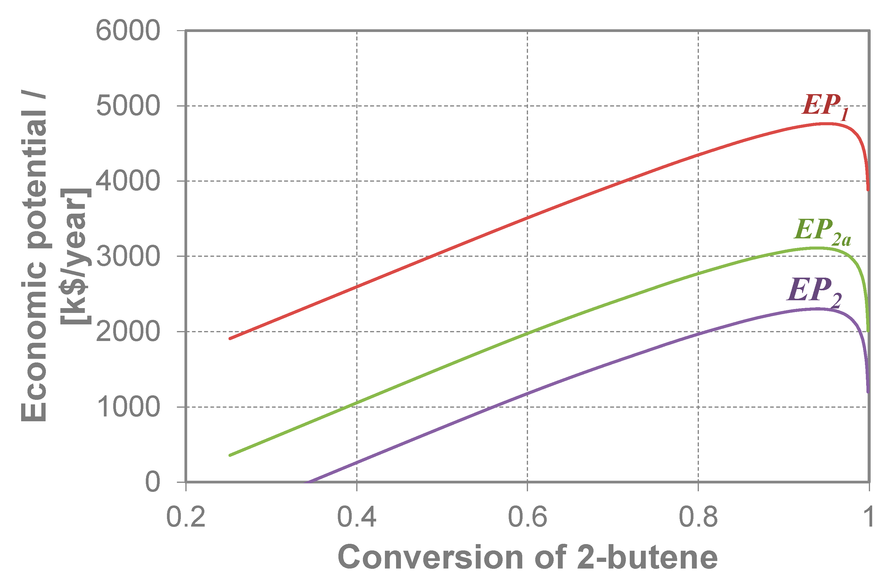
Andrei and Bildea [10] evaluated several process alternatives. By performing sensitivity studies, they showed that the most profitable alternative consists of a reaction section followed by product separation, without reactant recycling. This happens because of the close boiling points of butenes and n-butane, which make their separation very costly. In the present article, we present the optimization of the reaction–separation plant for the metathesis of 2-butene. Figure 1 shows the dependence of the economic potential EP versus the 2-butene conversion, calculated at different levels of detail. Thus, EP1 takes into account only the difference between product sales revenue and raw material cost. EP2a takes into account the investment and operating costs associated with the reaction. Finally, EP2 incorporates the costs of separation, including the distillation columns (column and reflux drum, condenser, reboiler, internals), cooling of the condenser, and heating of the reboiler. This preliminary analysis allows for finding the optimal value for conversion, which is the basis of a preliminary mass balance.
In the present article, the total annual cost (TAC) is used as the objective function. This approach, which conveniently combines capital expenditure (CAPEX) and operating expenditure (OPEX), has been used in many design and control studies [11,12,13]. These references also present the equations that can be used to estimate the installed equipment cost and give values for utility prices (high-pressure steam, 9.88 $/GJ; medium-pressure steam, 8.22 $/GJ; low-pressure steam, 7.78 $/GJ; electricity, 16.8 $/GJ; cooling water, 0.72 $/GJ; refrigerant at −20 °C, 7.89 $/GJ, refrigerant at −50 °C, 13.11 $/GJ). The restrictions of the optimization problem are represented by the mass and energy balance of the plant, together with the equilibrium and kinetic conditions, as implemented in the Aspen Plus models of the unit operation. The decision variables are described in the next sections.
2.4.2. Reaction Section
The reaction takes place in a fixed-bed, vapor-phase tubular reactor, which is operated adiabatically. This type of reactor was chosen because it is suitable for housing large amounts of catalyst and it is easy to operate. The reactor diameter was determined for a pressure drop of 0.01 bar/m (the typical value for single-phase fixed-bed catalytic reactors) and the corresponding cross-sectional area. A simulation of the chemical reactor, using the RPLUG Aspen Plus model, (Bedford, MA 01730, USA) allowed for the finding of the length necessary to achieve the required conversion.
2.4.3. Separation Section
The columns were sized using the DSTWU shortcut distillation model from Aspen Plus. The recoveries of the light and heavy key components were specified, together with the reflux ratio being 1.2 times the minimum value. The DSTWU model determined the data required by the RADFRAC rigorous model (the number of trays NT, reflux ratio R, feed tray location NF, distillate-to-feed ratio D:F). For all columns, two design specifications were used. The mole fraction of the heavy key component in the distillate was set to 0.1 mole%. The ratio between the light and the sum of light and heavy key components in the bottom was set to a target of 0.5 mole%. This ensured that, in the subsequent distillation column, it was possible to obtain the distillate with high purity. The variables adjusted to reach the specifications were the reflux and the distillate-to-feed ratios, R and D:F, respectively. Then, the location of the feed stage NF was changed in order to find the value leading to minimum reboiler duty, and the total annual cost TAC was evaluated. The procedure was repeated for a different number of stages NT until a minimum value of the TAC was obtained.
Column height was determined considering the number of actual stages calculated with the typical value of tray spacing 0.6 m and allowing for the equivalent of four trays of vapor disengaging at the top of the column and a residence time in the bottom of the column equivalent to three trays. The column diameter was determined using the tray sizing facility available in Aspen Plus. The vessels were sized based on a residence time to allow sufficient time to reject process perturbation and to ensure enough net positive suction head for the reflux pump.
The operating pressure for distillation columns was selected to allow the use of cooling water in the condenser (except for the first column, where refrigerant is used). Two levels of steam were used as a heating agent in the reboilers, super-heated medium-pressure steam (MPS) at 12 barg and 220 °C and low-pressure steam (LPS) at 3 barg and 140 °C, respectively.
2.4.4. Heat Exchangers
The heat exchangers were sized considering a minimum temperature approach of 15 °C for the shell and tube exchangers and a typical value of 200 W/m2/K for the overall heat transfer coefficient. The log mean temperature difference was calculated from the energy balance and, hence, the heat transfer area.
2.4.5. Process Control
The dynamics and control of the plant were assessed using Aspen Dynamics v.10 flow-driven dynamic simulation. Some basic controllers were automatically added by the Aspen software. The control structure follows standard industry practice and is described in the Results section. The flow, temperature, pressure, and composition controllers were conventional PI-type. The level controllers (reflux drums, the sumps of the columns, and feed vessels) were P-type. For most controllers, the gain was set to 1 (%OP range/% PV range), and the integral time was chosen as an estimation of the loop time constant [7]. Composition controllers were tuned by running a relay-feedback test with the Tyreus–Luyben tuning rule.
3. Results and Discussion
3.1. Process Description
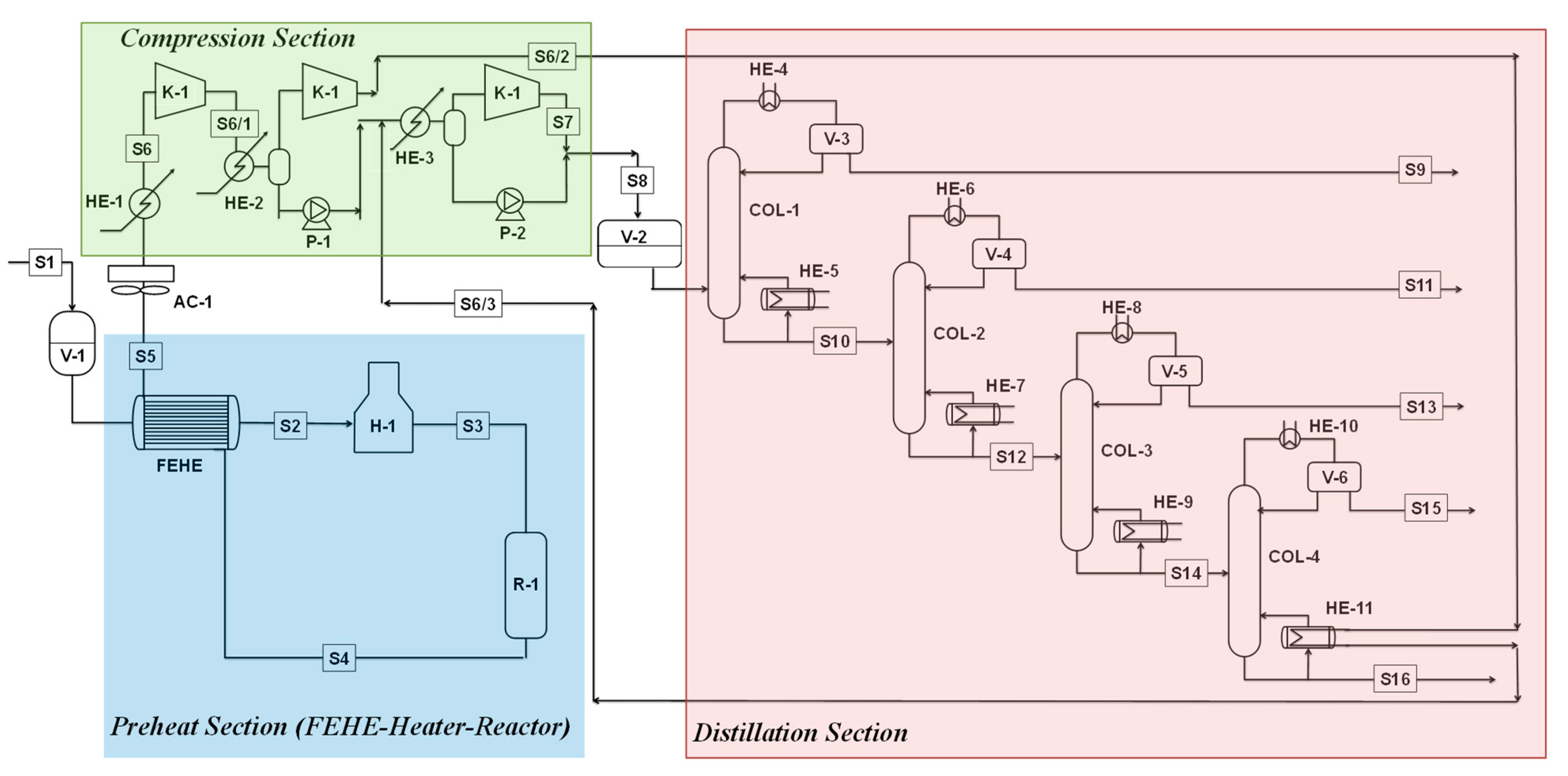
The olefin metathesis unit is a reactor-separation flowsheet consisting of preheat, heating, reaction, and separation sections (Figure 2). The low-value product nBB of the fluid catalytic cracking unit (FCCU) is pumped to the olefin metathesis unit from feed surge drum V-1. The feed consists of a mixture of 2-butene (70 mol%) as the reactant and n-butane (30 mol%) acting as inert. The feed surge drum (V-1) is sized to ensure sufficient holdup volume in case of an inadvertent pump trip and is operated at 8 bar(g) to ensure the feed mixture is kept in a liquid state. The fresh feed is routed to the feed-effluent exchanger (FEHE) and then to the furnace (H-1). The reaction section consists of an adiabatic tubular reactor operating at P = 1 bar and inlet temperature T = 550 °C with a tungsten oxide catalyst supported on silica. The reaction is conducted in the vapor phase and is slightly endothermic. The reactor effluent passes through the feed-effluent exchanger (FEHE) and is cooled in the air cooler (AC-1) and water cooler (HE-1) to ensure an acceptable temperature at the inlet of the compressor (K-1), typically below 50 °C. Prior to entering the separation section, the pressure of the reactor effluent is increased by the compressor (K-1). Moreover, heat can be recovered by using the hot, compressed stream S6/1 as a heat source in one distillation column reboiler (HE-10). The distillation section consists of four distillation columns separating ethylene C2 (99 mol%), propylene C3 (99 mol%), the C4 mixture of n-butane, 1-butene, 2-butene (99 mol%), pentene C5 (99 mol%), and hexene C6 (99 mol%). The direct sequence was chosen because it leads to the lowest energy requirements. Moreover, other heuristics [7,9] (such as “remove first the component in high amount” or “perform last the difficult separation”) do not apply here.
Table 2 presents the mass balance of the process. The 2-butene conversion is 90.4%. The product yields are (in kg product/100 kg C4 feed) 5.94 (ethylene), 19.72 (propylene), 33.5 (C4 hydrocarbons), 26.8 (pentene), and 14.0 (hexene).
3.2. Reaction Section
The olefin metathesis takes place in the vapor phase in a fixed-bed tubular reactor. The reactor is operated adiabatically at an atmospheric pressure of P = 1 bar. The inlet and outlet temperatures are 550 and 512.5 °C, respectively. The reactor diameter and length are D = 3 m and L = 9 m, for a total volume of 81 m3 (34 s residence time). The reactor employs 56.7 tonnes of catalysts. The reactor sizing results are shown in Table 3.
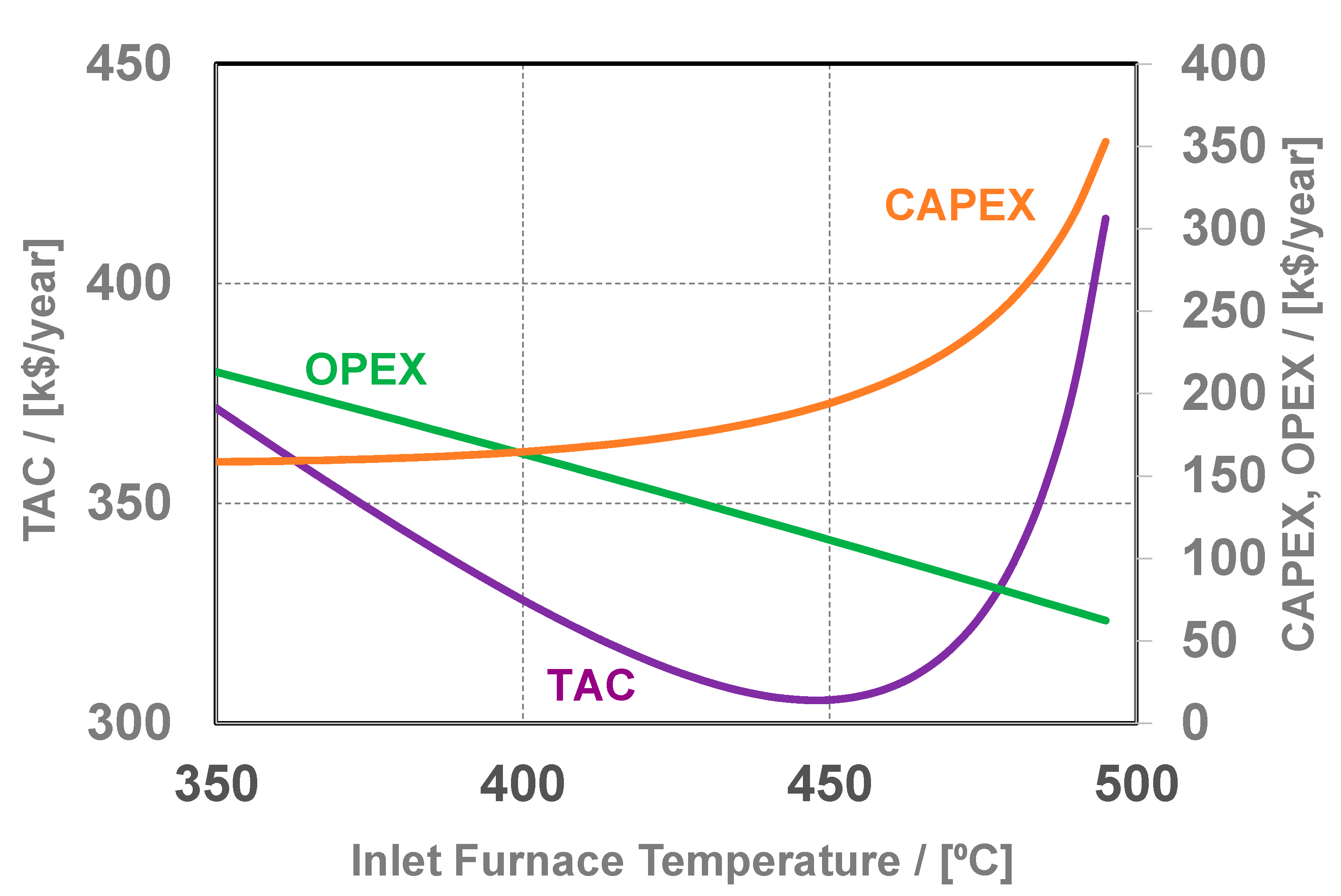
Figure 3 presents the results of optimizing the feed preheat section. As expected, the operating expenditure (OPEX) decreases with the furnace inlet temperature (because more heat is recovered). The capital expenditure (CAPEX) shows an opposite trend, as a more expensive feed-effluent heat exchanger is required for heat recovery. It turns out that the best solution is to preheat the fresh feed from 40 to 450 °C using the heat of the reactor effluent (512.5 to 150.9 °C) in a feed-effluent heat exchanger (1511.9 kW, 179 m2, log mean temperature difference 84.5 °C) and then to bring the mixture at the reaction temperature in a furnace (450 to 555 °C, 488 kW). The investment and operating costs are 205 × 103 $ and 100 × 103 $ /year, respectively.
3.3. Separation Section
The design of the distillation columns is summarized in Table 4. The ethylene column operates at 32 bar to allow the use of a refrigerant in the condenser. The operating pressures are lower for propylene, C4, and pentene columns, which use cooling water in their condensers. The total annual costs are in the range of 417–610 × 103 $/year. Note that the optimization procedure resulted in a 220 × 103 $/year (about 9.6%) reduction of the TAC compared to the base case design (based on the Underwood–Fenske shortcut method).
3.4. Process Control
3.4.1. Basic Process Control
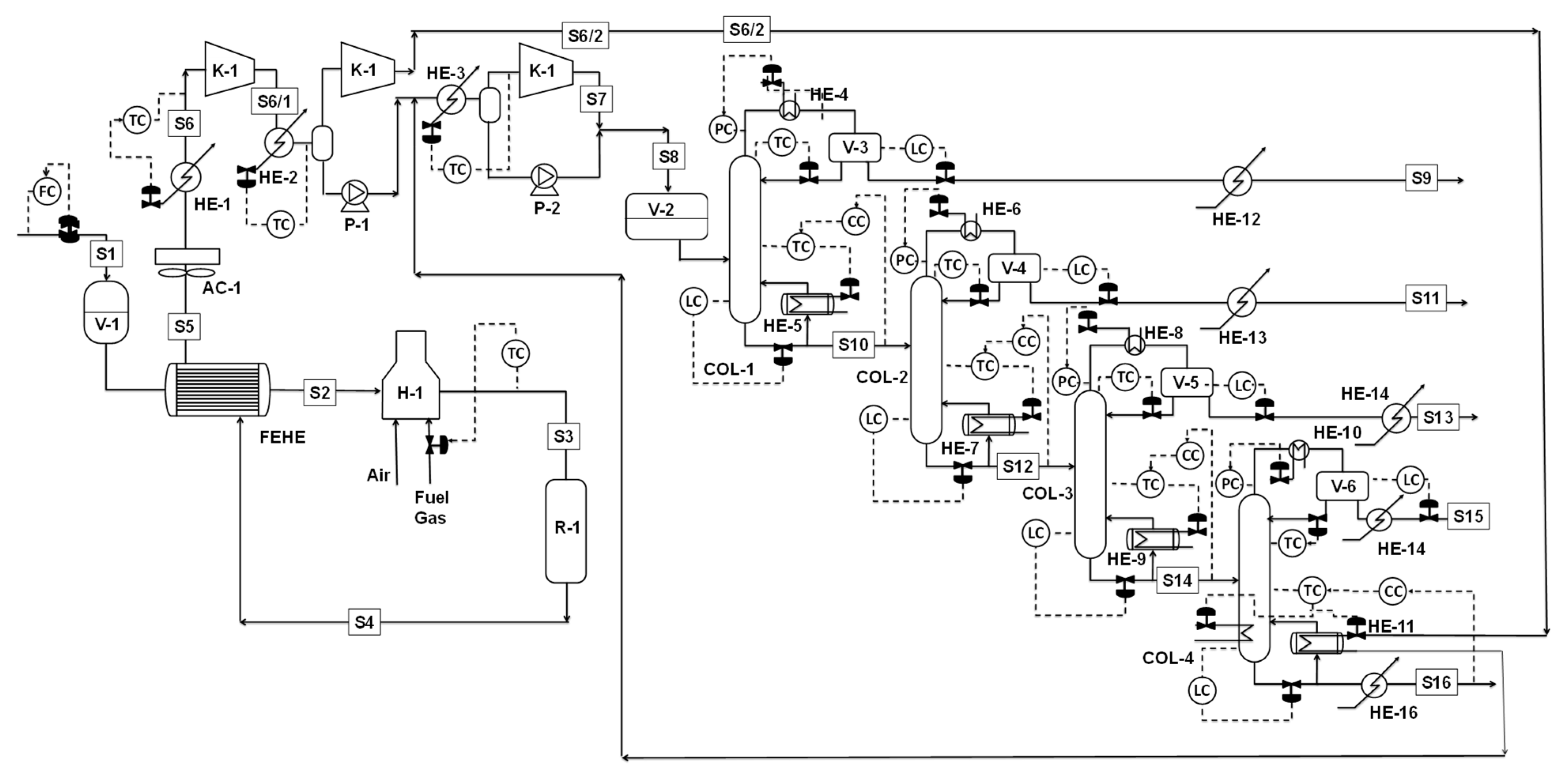
Figure 4 presents the plantwide control of the 2-butene metathesis process. After passing the feed-effluent heat exchanger (FEHE), the temperature of the feed stream at the reactor inlet is controlled by the furnace duty. Before being compressed and sent to the separation section, the temperature of the reactor-outlet mixture is controlled by the duty of the heat exchanger HE-1.
In the distillation section, each column is equipped with a pressure controller on the condenser and level controllers for the sump and reflux drums. All reflux drums and column sump are sized to provide sufficient holdup when the level is 50% full. The pressure is controlled by the condenser duty. The liquid holdups are maintained via the product flow rates. This approach for level control is best suited for relatively small reflux ratios (L/D) and boil-up ratios (V/B) [14].
The first distillation column is designed to separate the ethylene from the reactor effluent on the overhead. The specification of the ethylene product is kept by indirect composition control via a temperature controller provided on Tray 7, which manipulates the reflux rate. It should be noted that the location for all temperature-control trays is based on the “sensitivity criterion”, where the largest change in temperature for a change in the manipulated variables (either reflux ratio or reboiler duty) is observed [15].
Since there are four distillations columns in series and each distillate requires a relatively high-purity product, it is imperative to prevent the light product carryover in the bottom flow. A cascade of composition control (XC) and temperature control (TC) is employed. Similar to industrial practice, the composition control loops involve a 10 min sampling period and 10 min measurement dead time, while the temperature control loop is much faster.
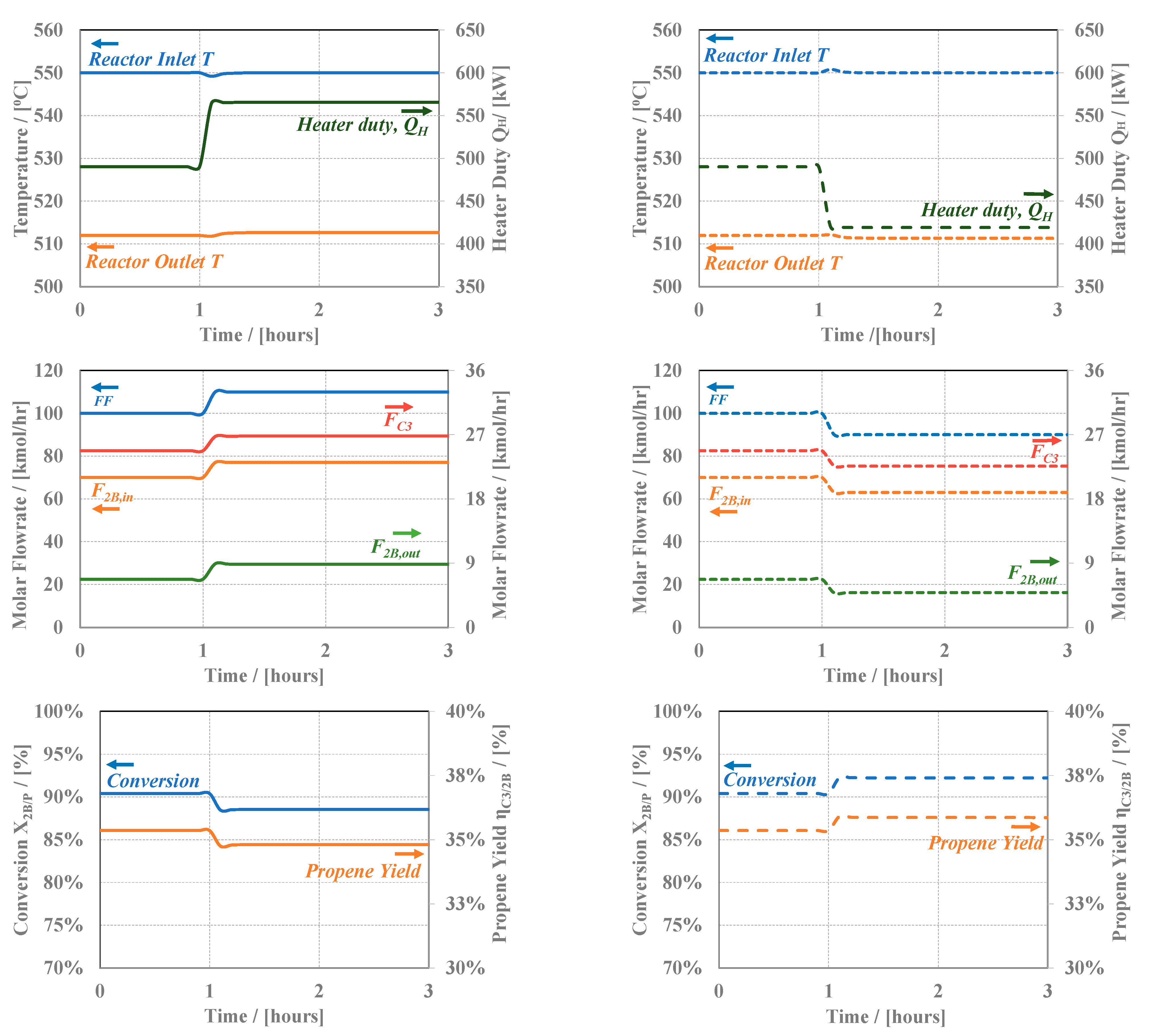
Figure 5 presents dynamic simulation results for feed flow rate disturbances. The simulation starts from a steady state, which is maintained for 1 h. Then, the feed flow rate (FF) is increased (left diagrams) or decreased (right diagrams) by 10%. The top diagrams show the performance of reactor-inlet temperature control, which succeeds in maintaining the temperature at the required value. The middle row shows the feed (FF—total, F2B,in—2-butene), propylene product (FC3), and unreacted 2-butene (F2B,out) reactor-outlet flow rates. The bottom row shows the change in 2-butene conversion and propylene yield. Lower/higher values of the residence times (due to a higher/lower flow rate) lead to an increase/decrease in the conversion. Note that the product formation rate is given by the feed rate × conversion. Among the two factors, the feed rate has the biggest influence. Thus, higher feed rates lead to more product being obtained. Note that the dynamics of the reaction section is fast because of low inventory.
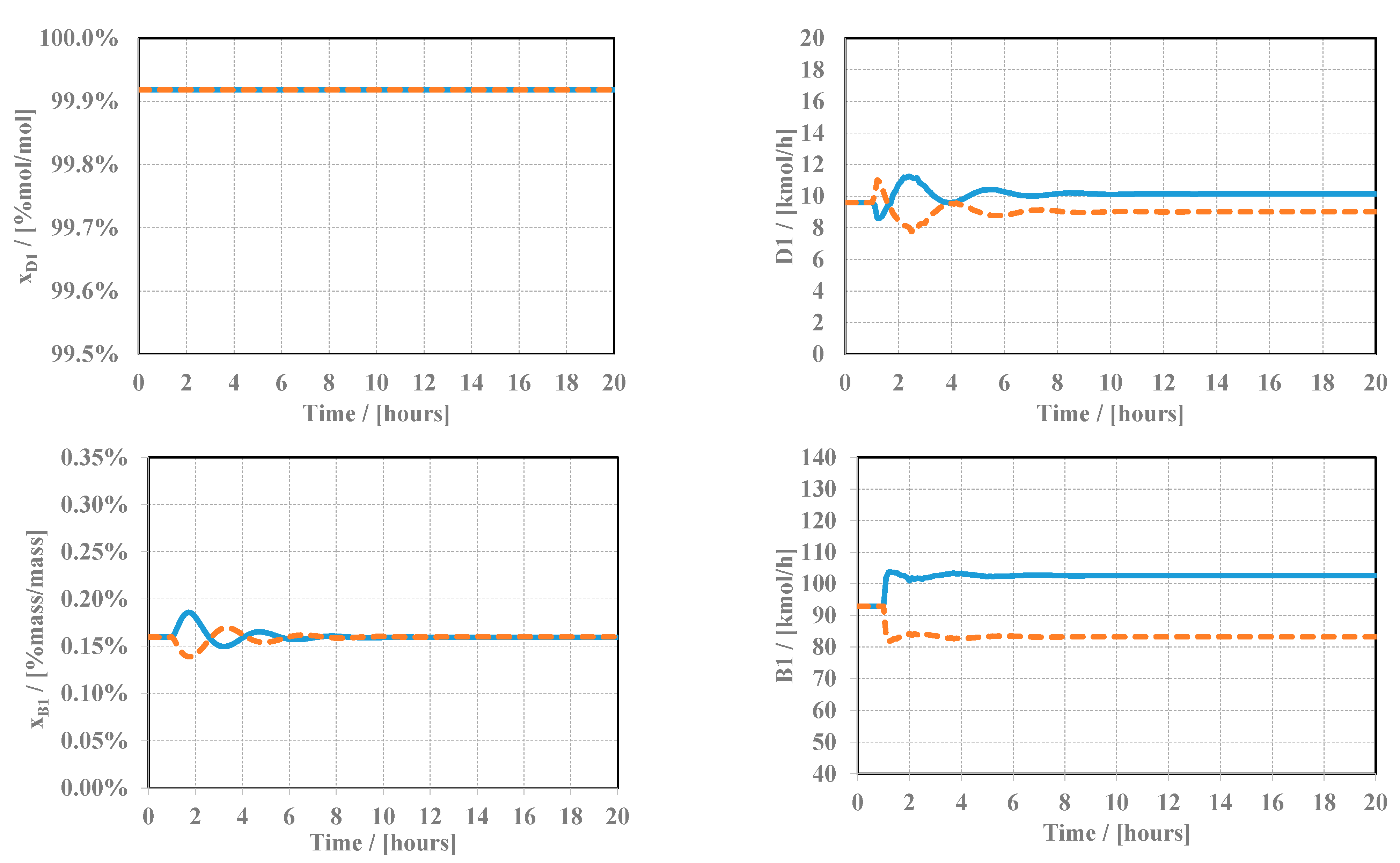
Figure 6 shows the dynamics of the ethylene column when the plant inlet flow rate increases (solid lines) or decreases (dashed lines). The distillate (D1) purity is practically not affected by the disturbance, but it takes several hours and a slight overshoot until the new production rate is reached. This can be explained by the rather large inventory of the reflux drum, which dampens the disturbances. Regarding the bottom stream (B1), the amount of ethylene lost here is limited, and the flow change is much faster.
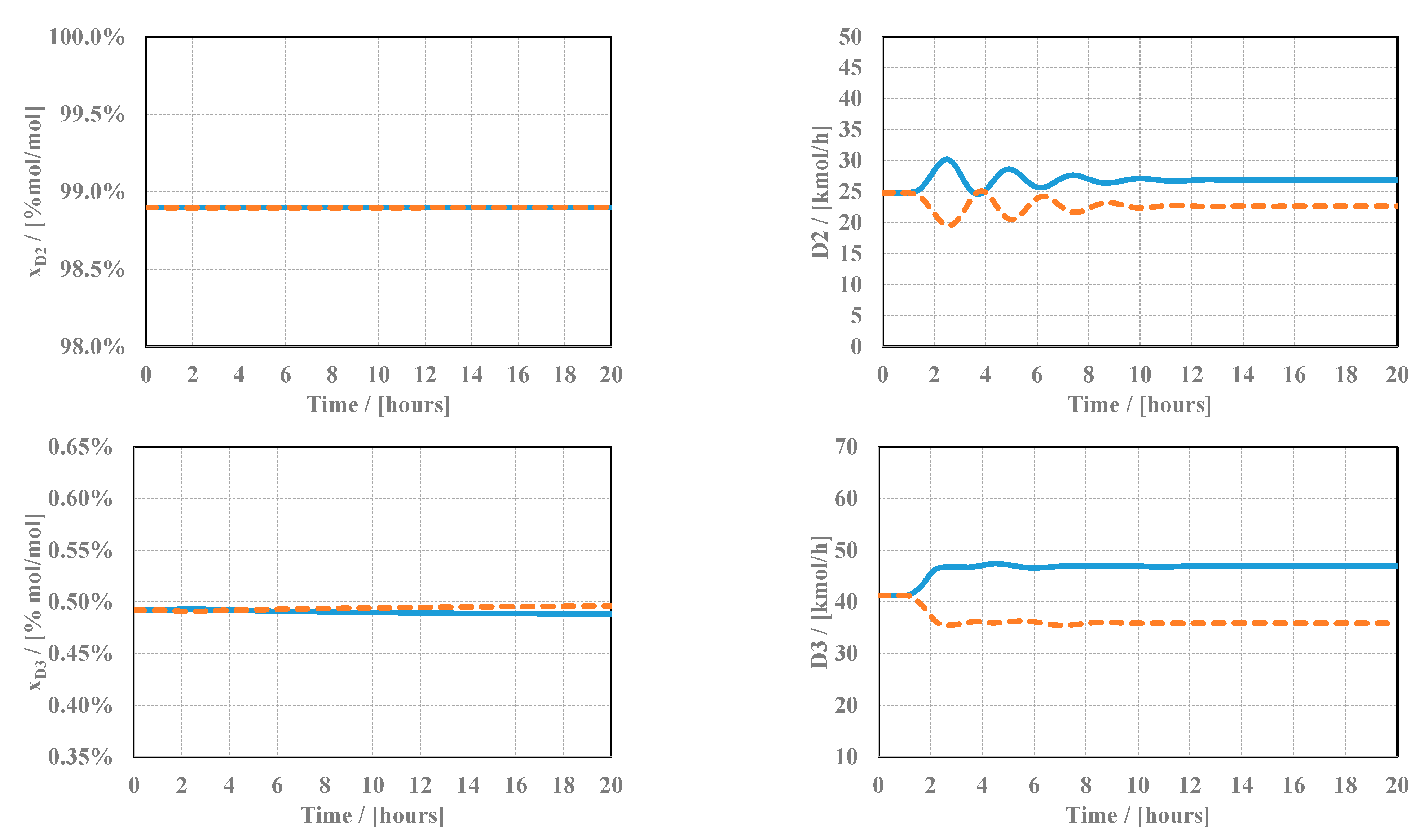
Figure 7 presents the performance of the propylene and C4 columns. The propylene purity (xD2) is practically unchanged, but the distillate rate (D2) transient regime lasts for several hours. The number of light olefins (ethylene and propylene, xD3) lost in the stream of C4 hydrocarbons (D3) is limited.
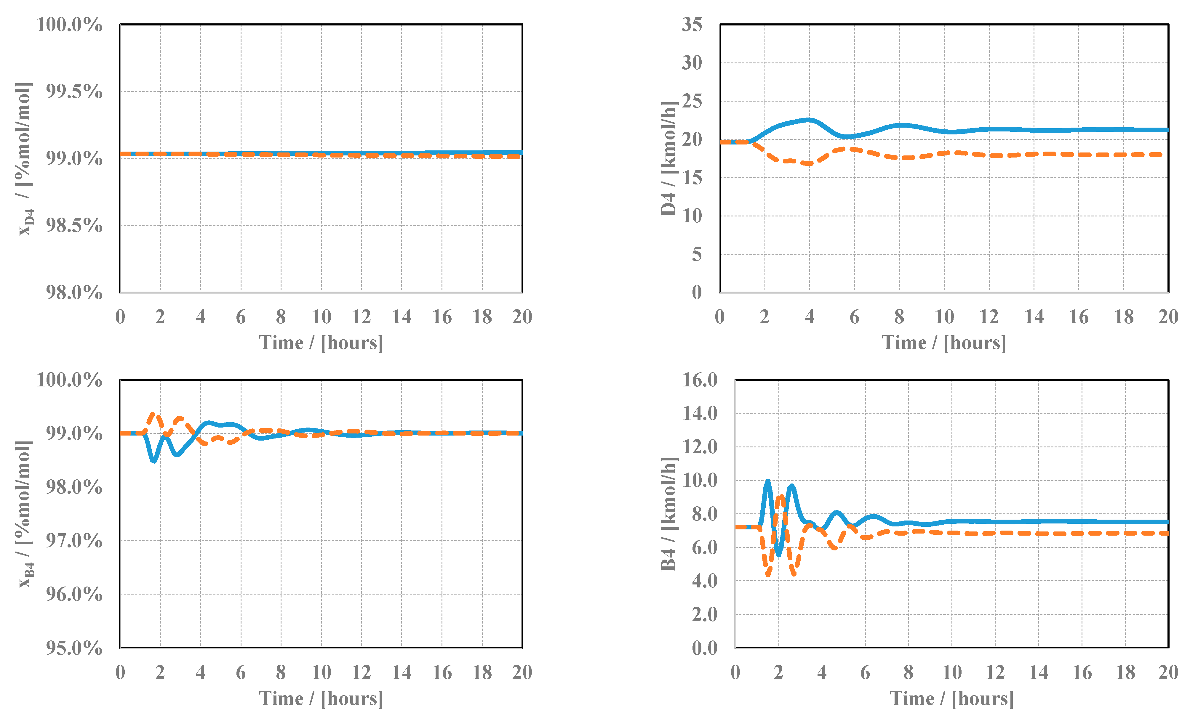
The dynamics of pentene (D4) and hexene (B4) products are shown in Figure 8. Similar to the other columns, the control system is able to keep the product purities close to their setpoints while the flow rates reach a new stationary value according to the increase/decrease in the fresh feed rate.
3.4.2. Safety Analysis
In the design phase, it is necessary to investigate and include the safety aspects concerning the unit as early as possible. One such safeguard is represented by the independent protection layers (IPLs), which operate on demand (during normal or abnormal events) and prevent or mitigate the risk of a hazard. Typically, the failure of one independent layer should not affect the next safety barrier. The IPLs are classified based on two important functions: prevention and mitigation. Several well-established methods for quantifying risk assessment in a plant are available in the literature. Companies have developed their in-house procedures and protocols for applying these methods within their risk management systems (e.g., LOPA, HAZOP), which are discussed in this work.
The intention of this section is to provide the reader with basic guidelines pertaining to the safety aspects applied for industrial equipment within the design phase, specifically, in this case, for the olefin metathesis plant.
Process control is the first line of defense that prevents injury to personnel, protects the environment, and ultimately prevents damage to company assets. It is followed by a process alarm with operator intervention, an emergency shutdown system (automatic valves for safety close/release of hydrocarbons), an active protection layer (safety valves or rupture disks), passive protection (dikes, fire extinguisher, monitors, fire and gas system), and, finally, the refinery emergency for evacuation.
The alarms have the primary function of alerting the operator that a variable has passed a predetermined critical limit, leading to a potentially dangerous situation. Some basic principles when configuring an alarm system should be considered, such as not overwhelming the operator with too many notifications (leading to overstressing and eventually silencing the alarm) and allowing enough time to take corrective measures (typically 60–120 s) from when the variable passes the normal operating range (e.g., low, normal, high levels), typically referred to as an operating window or envelope. The alarm sensor should be independent of the process control sensor, undoubtedly, if the reliability of the sensor is expected to be a weak point. Proper operator supervision and manual intervention, with periodical training sessions to increase the awareness of such situations and correct comprehension of process manuals and procedures, act as decisive factors in the development of experienced and well-trained operators in view of these possible events. Practically, an alarm sensor can be configured for each variable of a piece of equipment, given that there are available instruments to measure that specific variable (e.g., pressure, flow, temperature, level). Such alarms may operate in both directions, high deviation or low deviation, e.g., low pressure or high temperature.
In case the alarm system layer fails to prevent the propagation of the hazard, then the next independent protection layers should be available, namely the emergency shutdown (ESD) system.
The ESD system is represented by a well-established sequence of corrective measures (effects) initiated by a trigger or cause (represented by a process variable deviation/limit or operator pushbutton), which responds automatically to drive the process to a safe state when the deviation occurs and has not been corrected by the previous protection layers. Typical actions undertaken by an emergency shutdown system are the shutdown of certain equipment or sections of the process, hydrocarbon inventories isolation, the stopping of hydrocarbon flow, and, ultimately, depressurization and/or blow-down. Emergency shutdown systems can also be classified based on the actions undertaken and company standards. Most important is that these ESD systems have dedicated logic controllers, sensors, and actuators, separate from process control systems, to avoid the simultaneous failure of both protection layers. The architecture of such systems and safety functions is widely available and well-documented in the literature; however, several examples pertaining to the unit olefin metathesis are provided.
In case these prevention layers (process control, alarm system, and ESD) fail to propagate the hazard, then the next protection layer is available, specifically, the relief system designed to reduce or mitigate the risks of the hazard. The relief system consists in mechanical devices that open at a defined set pressure to protect equipment from exceeding allowable pressure levels by means of discharging gas, liquid, or vapor to a safe and reliable exit. The design pressure is calculated based on the maximum operating pressure of the equipment, system, or part of the unit, plus some additional margin in order to account for any errors in the calculation. The release can be achieved through dedicated mechanical devices designed and manufactured for equipment under pressure, e.g., pressure safety valves or rupture disks. These mechanical devices are positioned on pressure vessels or pipelines. The pressure of the relief device, i.e., the safety valve, is typically set at 10% above the normal operating pressure of the protected pressure equipment. However, other conditions may apply depending on the specific situation. In order to determine the capacity (flow) of the relief system, several scenarios are investigated, and the worst-case scenario is the one that returns the maximum flow of the mechanical device.
Typically, the release of hydrocarbons is collected in a flare header, represented by a series of sub-headers and headers, directed via a knock-out drum to separate the gases from the carryover liquid hydrocarbons, and finally, they are safely disposed of by means of combustion into a stack with a flare tip, also referred as a flare.
In case the release of hydrocarbons is imminent, then another (passive) protection layer is available to limit the spread of the hazard, such as a dike or fire and gas equipment (detectors, extinguishers, etc.), that ceases or reduces the amplitude of the hazard.
The final and least desirable protection layer is the plant emergency alarm and subsequent evacuation of personnel with the alert of a fire-fighting team.
Specifically, for the olefin metathesis unit, only the critical equipment is studied, e.g., reactor R-1, heater H-1, and compressor K-1, with regards to the alarm system and emergency shutdown (ESD) system (Table 5). The relief system is very equipment-specific and requires unit partitioning and thus is not investigated.
4. Conclusions
This article presents the economical optimization and dynamic control of a reactor reaction-separation flowsheet of 2-butene metathesis. The once-through configuration of reactor-separation design is determined as the most cost-effective solution. Low-value by-product from FCCU, 2-butene, is used as raw material to produce a high-value olefin, propylene. Two types of flowsheet designs are investigated [10], namely, with and without recycling. The first decision levels (input–output analysis and reactor selectivity) are not conclusive enough to select the most economical attractive flowsheet. With the optimal conversion determined around 90%, further consideration of the investment and operation costs related to separation equipment reveal that removing the inert from the reactants is costly because of low relative volatility. Alternatively, recycling substantial amounts of inert inside the plant contributes to higher capital costs and operating expenditures. It turns out that a simple reactor–separation flowsheet (without recycling) is the most attractive economical solution. This was a rather surprising result mostly because (for the case considered here) the product separation leaves a by-product stream containing reactants and the inert product, which has a rather high value and does not increase the additional disposal costs.
In the current work, the flowsheet of reactor separation is optimized economically for two sections of the unit: preheating and separation. For the preheating section, the decision variable is the furnace inlet temperature, which determines the energy savings and the heat transfer areas of the FEHE and furnace. These variables influence both the capital and operating costs.
For the separation section, comprising four distillation columns, the optimization variables are column pressure, the number of stages, feed location reflux, and distillate-to-feed ratios. The optimization results show that approximately a 10% reduction can be achieved for the operating and capital costs, returning a total annual cost of TAC = 2099 × 103 $/k$/year.
The dynamic response of the unit is studied for ±10% feed flow disturbance. The control system is more than capable of bringing the unit to a new steady state in a couple of minutes for the reactor section. The control system of the distillation columns succeeds in keeping the product purities close to their required values at all times. However, the dynamics of the product flow rate is slower, requiring several hours until the new steady state is reached.
Concerning the safety analysis, the independent protection layers are discussed, with the objective of highlighting the importance and necessity of setting independent safety layers in the design of any industrial plant.
The results prove that the metathesis reaction of 2-butene over a mesoporous tungsten catalyst is a viable opportunity to produce more valuable olefins (such as propylene) from low-value feedstock (such as 2-butene). The most economical solution is a reaction–separation plant (without recycling) with a profitability of 2300 × 103 $/year. For a 5.7 t/h feed rate consisting of 2-butene (70% molar) and n-butane (30% molar), the investment cost is 6570 × 103 $, giving a return of investment of ROI = 35%.
Author Contributions
Conceptualization, A.M.A. and C.S.B.; methodology, A.M.A. and C.S.B.; software, A.M.A.; writing—original draft preparation, A.M.A.; writing—review and editing, A.M.A. and C.S.B.; funding acquisition, C.S.B. All authors have read and agreed to the published version of the manuscript.
Funding
This research was funded by the European Commission through the European Regional Development Fund and the Romanian state budget, Grant Agreement 155/25.11.2016 (Project POC P-37-449, acronym ASPiRE). The APC was funded by the University Politehnica of Bucharest.
Data Availability Statement
No new data were created or analyzed in this study. Data sharing is not applicable to this article.
Conflicts of Interest
The authors declare no conflict of interest. The funders had no role in the design of the study; in the collection, analyses, or interpretation of data; in the writing of the manuscript; or in the decision to publish the results.
References
- Fazlinezhad, A.; Fattahi, M.; Tavakoli-Chaleshtori, R.; Rezaveisi, H. Sensitivity Analysis and Multi-Objective Optimization of Oxidative Dehydrogenation of Propane in a Fixed-bed Reactor over Vanadium/Graphene for Propylene Production. Chem. Eng. Techol. 2022, 45, 309–318. [Google Scholar] [CrossRef]
- Yuming, C.; Liu, N.; Xia, Y.; Lv, J. Efficient self-metathesis of 1-butene on molybdenum oxide supported on silica modified one-dimensional γ-Al2O3. J. Mol. Catal. A Chem. 2014, 394, 1–9. [Google Scholar]
- Lwin, S.; Wachs, I.E. Olefin Metathesis by supported Metal Oxide Catalysts. ACS Catal. 2014, 4, 2505–2520. [Google Scholar] [CrossRef]
- Mazoyer, E.; Szeto, K.; Merle, N.; Norsic, S.; Boyron, O.; Basset, J.-M.; Taoufik, M.; Nicholas, C. Study of ethylene/2-butene cross-metathesis over W-H/Al2O3 for propylene production: Effect of the temperature and reactant ratios on the productivity and deactivation. J. Catal. 2013, 301, 1–7. [Google Scholar] [CrossRef]
- Felischak, M.; Wolff, T.; Alvarado Perea, L.; Seidel-Morgenstern, A.; Hamel, C. Evaluation of Catalysts for the Metathesis of Ethene and 2-Butene to Propene. Catalysts 2022, 12, 188. [Google Scholar] [CrossRef]
- Mol, J.C. Industrial applications of olefin metathesis. J. Mol. Catal. A Chem. 2004, 213, 39–45. [Google Scholar] [CrossRef]
- Dimian, A.C.; Bîldea, C.S.; Kiss, A.A. Process Synthesis by the Hierarchical Approach. In Integrated Design and Simulation of Chemical Processes, 2nd ed.; Elsevier: Amsterdam, The Netherlands, 2014; Volume 35, pp. 253–300. [Google Scholar]
- Bhuiyan, T.I.; Arudra, P.; Hossain, M.M.; Akhtar, M.N.; Aitani, A.M.; Abudawoud, R.H.; Al-Khattaf, S.S. Kinetics modelling of 2-butene metathesis over tungsten oxide containing mesoporous silica catalyst. Can. J. Chem. Eng. 2014, 92, 1271–1282. [Google Scholar] [CrossRef]
- Douglas, J. Conceptual Design of Chemical Processes, 1st ed.; McGraw-Hill Science Engineering Math: Singapore, 1988; pp. 99–315. [Google Scholar]
- Andrei, M.; Bîldea, C.S. Conceptual Design of propylene production by metathesis of 2-butene. Univ. Politeh. Buchar. Sci. Bull. Ser. B-Chem. Mater. Sci. 2018, 80, 47–62. [Google Scholar]
- Dimian, A.C.; Bildea, C.S.; Kiss, A.A. Economic evaluation of projects. In Integrated Design and Simulation of Chemical Processes, 2nd ed.; Elsevier: Amsterdam, The Netherlands, 2014; Volume 35, pp. 572–604. [Google Scholar]
- Dimian, A.C.; Bildea, C.S.; Kiss, A.A. Applications in Design and Simulation of Sustainable Chemical Processes, 1st ed.; Elsevier: Amsterdam, The Netherlands, 2019; pp. 183–215. [Google Scholar]
- Luyben, W.L. Principles and Case Studies of Simultaneous Design, 1st ed.; AIChE Wiley: New York, NY, USA, 2011; pp. 53–57. [Google Scholar]
- Skogestad, S. The Dos and Don’ts of Distillation Column Control. Chem. Eng. Res. Des. 2007, 85, 13–23. [Google Scholar] [CrossRef]
- Luyben, W. Evaluation of criteria for selecting temperature control trays in distillation columns. J. Process Control 2016, 16, 115–134. [Google Scholar] [CrossRef]
Figure 1.
Economic potential vs. conversion of 2-butene for olefin metathesis unit.

Figure 2.
Olefin metathesis of 2-butene flowsheet.

Figure 3.
Feed preheat section: TAC, OPEX, CAPEX versus furnace inlet temperature.

Figure 4.
Metathesis process of 2-butene—flowsheet and plantwide control.

Figure 5.
Reactor dynamic stream results and performance for feed flow disturbance (solid lines indicate +10% FF, and dashed lines indicate −10%FF).
Figure 5.
Reactor dynamic stream results and performance for feed flow disturbance (solid lines indicate +10% FF, and dashed lines indicate −10%FF).

Figure 6.
Feed disturbances for COL-1 with feed step changes (solid lines +10%; dashed line −10%).

Figure 7.
Feed disturbances for COL-3 and COL-4 with feed step changes (solid lines are +10%; dashed lines are −10%).
Figure 7.
Feed disturbances for COL-3 and COL-4 with feed step changes (solid lines are +10%; dashed lines are −10%).

Figure 8.
Feed disturbances for COL-4 with feed step changes (solid lines are +10%; dashed lines are −10%).
Figure 8.
Feed disturbances for COL-4 with feed step changes (solid lines are +10%; dashed lines are −10%).


Table 1.
Parameters of the kinetic model.
| Reaction | Pre-Exponential Factor k(T0) (m3/kmol/s) | Activation Energy Ea (kJ/kmol) | Ai | Bi (K) |
|---|---|---|---|---|
| 1 | 0.0287 | 25.12821 | 4.662791 | −1154.68 |
| 2 | 6.802 | 102.0203 | 5.480296 | −144.335 |
| 3 | 3.815 | 187.0776 | 9.544931 | −3139.28 |
| 4 | 0.123 | 84.56967 | 20.7 | 0 |
Table 2.
Mass balance for the olefin metathesis flowsheet.
| Stream | U.M | S1 | S2 | S3 | S4 | S5 | S6 | S6-1 | S6-2 | S6-3 | S7 |
|---|---|---|---|---|---|---|---|---|---|---|---|
| Temperature | °C | 40 | 450 | 550 | 511.7 | 149.7 | 50 | 114 | 115.1 | 89.6 | 108.6 |
| Pressure | bar | 7 | 1.1 | 1 | 0.895 | 0.845 | 0.745 | 3.5 | 14 | 13.9 | 34 |
| Vapor Frac | 0 | 1 | 1 | 1 | 1 | 1 | 1 | 1 | 1 | 1 | |
| Mole Flow | kmol/h | 100 | 100 | 100 | 102.5 | 102.5 | 102.5 | 102.5 | 97.8 | 97.8 | 1.34 |
| Mass Flow | kg/h | 5671 | 5671 | 5671 | 5671 | 5671 | 5671 | 5671 | 5346 | 5346 | 53.2 |
| Mole Fraction | |||||||||||
| 2-Butene | 0.7 | 0.7 | 0.7 | 0.065 | 0.065 | 0.065 | 0.065 | 0.065 | 0.065 | 0.026 | |
| 1-Butene | 0.042 | 0.021 | 0.021 | 0.021 | 0.042 | 0.042 | 0.021 | ||||
| Propylene | 0.242 | 0.259 | 0.259 | 0.259 | 0.242 | 0.242 | 0.259 | ||||
| 2-Pentene | 0.191 | 0.209 | 0.209 | 0.209 | 0.191 | 0.191 | 0.209 | ||||
| Ethylene | 0.1 | 0.117 | 0.117 | 0.117 | 0.1 | 0.1 | 0.117 | ||||
| 3-Hexene | 0.07 | 0.092 | 0.092 | 0.092 | 0.07 | 0.07 | 0.092 | ||||
| n-Butane | 0.3 | 0.3 | 0.3 | 0.29 | 0.29 | 0.29 | 0.29 | 0.29 | 0.29 | 0.133 | |
| Stream | U.M | S8 | S9 | S10 | S11 | S12 | S13 | S14 | S15 | S16 | |
| Temperature | °C | 55 | −15 | 140 | 40 | 154 | 40 | 112.7 | 40 | 40 | |
| Pressure | bar | 32.9 | 32 | 34.2 | 25.5 | 25.5 | 6.5 | 7.5 | 2.5 | 3.5 | |
| Vapor Frac | 0 | 0 | 0 | 0 | 0 | 0 | 0 | 0 | 0 | ||
| Mole Flow | kmol/h | 102.5 | 12.0 | 90.5 | 26.5 | 64 | 32.8 | 31.2 | 21.74 | 9.42 | |
| Mass Flow | kg/h | 5671 | 337 | 5334 | 1118.2 | 4215.3 | 1901.3 | 2314 | 1520.9 | 793.1 | |
| Mole Fraction | |||||||||||
| 2-Butene | 0.065 | 0.01 | 0.01 | 0.01 | 0.014 | 0.019 | 0.01 | 0.01 | 0.01 | ||
| 1-Butene | 0.021 | 0.01 | 0.024 | 0.01 | 0.034 | 0.067 | 0.01 | 0.01 | 0.01 | ||
| Propylene | 0.259 | 0.01 | 0.294 | 0.99 | 0.01 | 0.01 | 0.01 | 0.01 | 0.01 | ||
| 2-Pentene | 0.209 | 0.01 | 0.236 | 0.01 | 0.335 | 0.01 | 0.687 | 0.99 | 0.01 | ||
| Ethylene | 0.117 | 0.99 | <0.01 | 0.01 | 0.01 | 0.01 | 0.01 | 0.01 | 0.01 | ||
| 3-Hexene | 0.092 | 0.01 | 0.104 | 0.01 | 0.147 | 0.01 | 0.303 | 0.01 | 0.99 | ||
| n-Butane | 0.29 | 0.01 | 0.331 | 0.01 | 0.469 | 0.913 | 0.01 | 0.01 | 0.01 | ||
Table 3.
Reactor design results.
| Reactor Tag | R-1 |
|---|---|
| Reactor type | Adiabatic tubular reactor |
| Inlet temperature (°C) | 550 |
| Outlet temperature (°C) | 512.5 |
| Inlet pressure (bar) | 1 |
| Diameter (m) | 3 |
| Length (m) | 9 |
| Volume (m3) | 81 |
| Residence time (s) | 34 |
| Pressure drop (bar) | 0.105 |
Table 4.
Design of the distillation columns.
| COL-1 | COL-2 | COL-3 | COL-4 | |
|---|---|---|---|---|
| Column description | Ethylene column | Propylene column | C4-column | Pentene column |
| Top pressure (bar) | 32 | 17 | 3.9 | 1.15 |
| Top temperature (°C) | −10.7 | 40.8 | 40 | 40 |
| Reflux ratio, RR | 3.72 | 4.7 | 1.34 | 1.13 |
| Number of stages, NTT | 30 | 38 | 30 | 28 |
| Feed location, NF | 13 | 15 | 15 | 16 |
| Reboiler duty, QR (kW) | 444.3 | 353.2 | 339.2 | 244.3 |
| Reboiler temperature (°C) | 137 | 125 | 92 | 77 |
| Steam type | MPS | MPS | LPS | LPS |
| Condenser duty, Qc (kW) | −87.8 | −501.5 | −544.8 | −295.6 |
| OPEX (103 $/year) | 185 | 140 | 95 | 60.6 |
| CAPEX/Payback (1000 $/year) | 421 | 440 | 438 | 357 |
| TAC (103 $/year) | 607 | 580 | 533 | 417.6 |
Table 5.
Alarm and shutdown settings for 2-butene metathesis unit.
| Variable | Normal Operation | Alarm System | Trip System (ESD) | ||||||
|---|---|---|---|---|---|---|---|---|---|
| Instrument | Value (NP) | Instrument | Value | Type | Instrument | Trip Value | Trip Group | ||
| Compressor K-1 | |||||||||
| Molar flow | Flow | FC-001 | 102.5 kmol/h | FC-002 | 75% of NP | Flow Alarm Low (FAL) | FSLL-001 | 60 kmol/h | IS-1 |
| Discharge temperature | Temperature | TI-001 | 115 °C | TI-002 | 125 °C | Temperature Alarm High (TAH) | TSHH-001 | 135 °C | IS-1 |
| High level in compressor K.O drum | Level | LIC-001 | 600 mm | LIC-002 | 700 mm | Level Alarm High (LAH) | LSHH-001 | 900 mm | IS-1 |
| Suction temperature | Temperature | TI-003 | 50 °C | TI-004 | 60 °C | Temperature Alarm High (TAH) | TSHH-002 | 110 °C | IS-1 |
| Heater H-1 | |||||||||
| Outlet temperature | Temperature | TI-004 | 550 °C | TI-005 | 560 | Temperature Alarm High (TAH) | TSHH-003 | 570 °C | IS-2 |
| Fuel gas to main burner | Pressure | PDI-001 | 3.5 barg | PDI-002 | 3.7 barg | Pressure Alarm High (PAH) | PSHH-01 | 5 barg | IS-2 |
| PDI-003 | 2.5 barg | Pressure Alarm High (PAL) | PSLL-001 | 2 barg | IS-2 | ||||
| Level in fuel gas K.O drum | Level | LIC-003 | 600 mm | LIC-004 | 700 mm | Level Alarm High (LAL) | LSHH-002 | 900 mm | IS-2 |
| Heater H-1 skin temperature | Temperature | TI-006 | 600 °C | TI-007 | 620 °C | Temperature Alarm High (TAH) | TSHH-004 | 640 °C | IS-2 |
| O2 content in furnace, H-1 | Analyzer GC | AI-001 | 2 vol% | AI-002 | 4 vol% | Analyzer Alarm Low (AAL) | ASLL-001 | <0.5 vol% | IS-2 |
| Reactor R-1 | |||||||||
| Inlet temperature | Temperature | TI-008 | 550°C | TI-009 | 570 °C | Temperature Alarm High (TAH) | TSHH-005 | 590 °C | IS-3 |
| Pressure drop | Pressure | PDI-003 | 0.1 bar | PDI-004 | 0.2 | DP Alarm High (DPAH) | |||
Disclaimer/Publisher’s Note: The statements, opinions and data contained in all publications are solely those of the individual author(s) and contributor(s) and not of MDPI and/or the editor(s). MDPI and/or the editor(s) disclaim responsibility for any injury to people or property resulting from any ideas, methods, instructions or products referred to in the content. |
© 2023 by the authors. Licensee MDPI, Basel, Switzerland. This article is an open access article distributed under the terms and conditions of the Creative Commons Attribution (CC BY) license (https://creativecommons.org/licenses/by/4.0/).
Share and Cite
MDPI and ACS Style
Andrei, A.M.; Bildea, C.S. Optimization and Control of Propylene Production by Metathesis of 2-Butene. Processes 2023, 11, 1325. https://0-doi-org.brum.beds.ac.uk/10.3390/pr11051325
AMA Style
Andrei AM, Bildea CS. Optimization and Control of Propylene Production by Metathesis of 2-Butene. Processes. 2023; 11(5):1325. https://0-doi-org.brum.beds.ac.uk/10.3390/pr11051325
Chicago/Turabian StyleAndrei, Andrei Maxim, and Costin Sorin Bildea. 2023. "Optimization and Control of Propylene Production by Metathesis of 2-Butene" Processes 11, no. 5: 1325. https://0-doi-org.brum.beds.ac.uk/10.3390/pr11051325
Note that from the first issue of 2016, this journal uses article numbers instead of page numbers. See further details here.