1. Introduction
Surge protection devices using ZnO-based varistors, known as metal oxide varistors, have originally been designed for medium and high voltage applications [
1]. They have also been developed for the low voltage range since the 1980s. Today, they are the most technical solution to make effective surge protections for all voltage levels [
2].
Each varistor manufacturer has its own “recipe” for the manufacturing process of varistors, starting from the initial chemical composition and ending with the manufacturing process operations themselves. Only a few processes are standardized, providing a set of well-defined operation sets to the user through standardized procedures. The parameters of the varistors manufacturing process are extremely important for their performance [
3]. However, in the desire to simplify manufacturing technology, many varistor manufacturers, especially non-traditional companies and Research & Development support, completely ignore many aspects of these parameters [
1].
The main requirements for varistors, irrespective of their field of application, are:
Threshold voltage sufficiently high for an excellent response to all types of stresses;
Good behavior on electrical, thermal, chemical and mechanical stress (or combined) [
4];
Highest absorption capacity in energy;
Low electrical capacity (for telecommunication applications mostly);
Aging as slow as possible [
5];
Lowest price;
The possibility of manufacturing on an industrial scale.
Obviously, these requirements, which are the “minimal varistor specifications”, are ideal. There is no such varistor in practice, and the varistor manufacturing process must consider the compromise between all these properties [
6].
The threshold voltage also depends on the average size of ceramic zinc oxide microcrystals. It is therefore essential that we can control their size, which requires the study of two types of parameters:
From all the oxides important to the varistor composition, most have direct effect on the granulometric composition. In terms of synthesis, a classical behavior for ceramics can be observed, where the size of the crystals increases with the heating temperature range. Under these conditions it is possible to vary the size of the zinc oxide granules between 3 and 80 μm.
2. Existing Manufacturing Process of Metal Oxides Varistors
The manufacturing of varistors is a conventional ceramic process. It is a succession of operations where many parameters are likely to influence the quality of the finished product. The way of manufacturing zinc oxide varistors has been little changed since they were discovered. Instead, studies in the field of ceramics, chemistry and electrical engineering have allowed optimization of electrical characteristics and thermal performance.
Most of the manufacturing process data were empirically obtained. Subsequently, there were also models to explain (in whole or in part) the complex process of manufacturing varistors based on mixtures of metallic oxides. Even though for the time being metal oxide based varistor manufacturing technology is in a saturated process, new elements are expected in the future to optimize their performance from the manufacturing stage.
Inside a ZnO based metal oxide varistor with, the highest percentage of material is over 90% (molar concentration) ZnO (over 80% mass concentration) and the composition is balanced by the addition of other metal oxides. As we have already mentioned, several additional oxides can be added to make the properties of the varistor material: Bi, Pr, Ba, Sr, La, Co, Mn, Ni, Cr, Sb, Si, B, Ti and others [
8].
Oxides used as starting material are in the form of crystalline powders. Crystal sizes are variable, depending on the type of oxides, but remain below 10 μm, with ZnO crystals being the basis of the composition.
The threshold voltage essentially depends on the particle size granulation of the metallic oxide powder. In general, if a good quality varistor is desired, the following considerations must be considered:
Control of the properties of the raw materials in the composition (purity, chemical reactivity, granulometric distribution, density, etc.);
Preparation of a homogeneous powder;
Respecting the thermal treatment parameters;
Permanent atmosphere control of the furnace during heating [
9];
Nature and technology of application of metallized electrode substrate;
Type and thickness of epoxy resin clothing.
Nowadays, over one billion varistors are in service, with operating voltages ranging from 5 V to 10 kV (and even more), and are primarily used as voltage suppressors, but also as voltage regulators. It is a booming industry, with the home appliance applications of varistors dating back to the 1980s and 1990s. Soon, by generalizing new standards for the protection of consumer electronics or similar domestic ones, automotive electronics and power supplies for computer technology and automation, the market would be able to take up approx. 10 billion varistors over the next 10 years, being comparable to the classical “semiconductor” applications market. Unfortunately, the number of manufacturers is relatively small [
10]. Regardless of the type, size, application range and composition of the varistors, the manufacturing operations are identical.
The main steps for the manufacturing process of metal oxide varistors are:
In general, most of the constituent oxides are commercially available, and it is not necessary to produce them in the laboratory, which contributes to a relatively low manufacturing cost, especially when working on an industrial scale.
2.1. Main Operations of the Manufacturing Process
All references are made to the technology developed in the “Génie Electrique”—LAPLACE laboratory of PAUL SABATIER University in Toulouse [
8] and applied by the authors for the purpose of making a series of varistors used in subsequent experiments and for familiarization with technological operations.
Figure 1 shows all the phases of a classical varistor manufacturing process:
The technological process operations are [
8]:
2.1.1. Weighing
Component weighing was performed with an electronic balance, which can accurately weigh more than 0.1 milligrams. The operation is relatively simple because all the oxides are delivered in the form of powders, for which granulometry is well determined. The initial chemical composition of the studied varistors with 2 and 5 additives will be detailed later.
2.1.2. Grinding and Mixing
It is, in fact, a homogenization of the mixture of oxides. Milling is necessary to facilitate this. After weighing, the oxides are milled in a ball cylinder. This mixing operation is made much easier in the liquid phase by the addition of distilled water and organic polymerization agent. This operation takes about 30 h. Reduced amounts of material are produced due to the limited capacity of the ball mixer.
2.1.3. Light Heating, Drying and Dry Grinding
The resulting material in the previous step is viscous and plastilineous. The paste obtained in the previous step is dried by exposure over a heated plate, or in an oven, until complete evaporation of the water occurs. After this operation, the resulting powder has a non-uniform grain size. Therefore, it must be milled again, but this time a dry grinding takes place on an average of 8–10 h. Prior to milling the homogeneous powder is again subjected to preheating, at approx. 200 °C. This preheating is carried out with the help of a thermostated oven.
2.1.4. Pressing
The powder is poured into a cylindrical shape and then pressed to 400–600 bar. This pressing is different from the pressing performed for sintering purposes. The dimensions of the pills to be obtained (and of course the pressing molds) are determined according to the nominal current (diameter) and the threshold voltage (pillow height) to be assured. For our research, we have opted for the useful diameters of 30 mm, disk varistors, having a height of 3 mm.
2.1.5. Sieving
Prior to pressing and casting, the mixture undergoes a preheat, this time at over 700 °C. Even though the dry grinding has led to a largely acceptable granulation, after the dry grinding, sieving is carried out in order to separate the granules from the powder with a size greater than 200 μm. This operation facilitates filling of shapes and then pressing of powder into these shapes.
2.1.6. Sintering
This is the most important operation because the parameters of the thermal cycle depend very much on the physicochemical reactions between the different constituents, the structure and the properties of the varistor. Thermal cycle parameters are different from one varistor manufacturer to another. But, as an order of magnitude, they are identical. In the first phase, an increase with a low temperature gradient (for 10 h), up to 400 °C, is performed, maintaining a constant temperature for 3 h. At this stage, any traces of waste water are removed [
11].
Thereafter, the increase is made up to 840 °C, with a pitch of at least one hour at this temperature. In this phase the crystalline structure of the material is realized. In the last phase an increase to 1250 °C is again carried out and then a slow cooling down to ambient temperature occurs [
12]. Due to the large number of constituents and the stages of the thermal process as well as the high temperatures, the physicochemical knowledge of the processes inside the varistor is still imperfect. During heating at 1250 °C partial vaporization of the additive oxides, first of the bismuth oxide, occurs.
The varistor’s heating is obviously uneven, being more important at the surface than in the center. Regardless of the chemical composition of the varistors, in industry the thermal cycle parameters are the same.
This operation results in a reduction in the initial volume of the pill [
10] by about 20%, an increase in density to the theoretical density of 5.7 kg/m
3. Density reaches 98–99% of this theoretical value. This fact will be highlighted by the final size of the pill (the diameter decreases by 10% in all manufactured series and the height decreases by 15%).
At this stage, the varistor body is finalized, and its color is dark grey. It is slightly brisk, but more resistant than after pressing. After reheating, its color will become light grey, with increased mechanical strength.
2.1.7. Deposition of Electrodes
After the samples are sintered, a conductive paste, based on Ag or less rarely by Al, is deposited on the two sides of the cylindrical tablet by serigraphy or brush, these surfaces constituting the varistors or varistor cylinder electrodes.
2.1.8. Varistor Reheating
The previously deposited paste has an organic polymer in its composition. For the paste on the front surfaces to become metallic and therefore to form the pill electrodes, a heat treatment of reheating above 600 °C is required. The removal of the solvent and the polymerization on the surface of the electrodes are carried out, Ag and Al being embedded in the polymer structure [
13]. The bonding wires can be added to the layer thus formed by gluing or welding.
2.1.9. Covering the Side Surface with Resin
An insulating epoxy resin is deposited on the periphery of the sample. This lining is made in order to protect the varistor against the action of the environment, chemical aggressions, but especially to avoid any overburden that may occur in the application of high amplitude current and voltage shocks. The varistor is preheated to 220 °C for 2–3 h so that the resin adheres perfectly and polymerizes on the side surface. The epoxy resin may fully incorporate the varistor or may be deposited only on the side surface of the varistor. 30 mm disc varistors were chosen for this solution, and for 20 mm the full coverage was achieved [
14]. The thickness of the epoxy resin layer is approx. 1 mm for the low voltage range. After this operation, the varistors will be subjected to quality assurance and quality assurance tests, which will then be presented.
2.2. Main Directions for Process Optimization
When resuming the manufacturing process of Metal Oxide Varistors, we can say that additional oxides are used for impurification (“doping”) in powder formation, with dimensions of several microns, and they are weighed and mixed with zinc oxide, by using grinding balls. The duration of this operation is about several hours, in a wet environment, with the addition of organic products such as binders and lubricants, in order to facilitate subsequent operations. This last operation allows obtaining a “spheroids based” powder of 100 mm diameter. The powder is pressed into a mold with a suitable shape, and the samples obtained are then sintered at 1000–1300 °C. This operation is very important because it ensures the crystal growth of ZnO grains and the formation of the microstructure on which the varistor’s electrical properties depend [
15].
The addition of other additives does not change the electronic microstructure of the energy bands, but also contributes to the improvement of the electrical characteristics of the obtained material. Thus, if the Sb and Cr oxides limit the size of the granules, Ti or Si favors their growth.
Aluminum, through its nitrates and oxides, reduces the resistivity of the material, while Li has a contrary effect. A systematization of the influence of each component on the physicochemical and electrical properties is not clearly obtained.
Even the electrical conduction of the varistor is determined by the potential barriers that form in the intergranular spaces. As we have shown in previous chapters, this preparation of the initial composition is based on much empiricism and experiments [
16].
Improving the electrical properties of varistors can be done both by optimizing the concentration of each constituent and by altering the parameters of the thermal sintering cycle.
It is noted that these varistors, produced by the authors, are made to be relatively coarse and artisanal, and cannot be put on the market. However, their electrical properties are good enough.
3. New Material Compositions
As their name implies, varistors are largely composed of ZnO, to which several oxides are added, each of which has a role. The simplest chemical composition of a varistor material has been developed by M. Matsuoka since 1968. Being of remarkable simplicity but characterized by a high quality, it is still cited as a reference point for any other manufacturing technology.
We will present a simple new material, based on a set of 5 additive oxides (and another one, with only 2), namely Bi
2O
3, MnO
2, Co
3O
4, Cr
2O
3 and Sb
2O
3 [
17]. This final composition has been improved over the years by the authors during their stages at the Génie Electrique Laboratory—LAPLACE, from the PAUL SABATIER University in Toulouse [
8]. The authors have perfected this composition along with a new manufacturing technology. With this relatively simple manufacturing technology, general-purpose varistors can be produced for civil applications, especially in the energy field, while less so in electronics, telecommunication, or military applications. The approximate chemical composition of a new original varistor, developed by the author in L.G.E.—Laplace Toulouse, with 2 and with 5 additive oxides, after completion of all manufacturing operations is given in
Table 1 and
Table 2.
It is unanimously recognized that the improvement of the electrical performance can be achieved by increasing the number of additives, optimizing their concentration and establishing optimal thermal cycles.
The first varistors developed during the 1950s and 1960s had ZnO as their main component, along with a single additive, like, for example, TiO
2, SiO
2, SnO
2. As we know, the main progress was made when it was introduced Bi
2O
3 as an additive, which virtually introduced the double junction at the intergranular layer [
18].
Some authors have attempted to dope zinc oxide with oxides of metals such as La or Pr, achieving excellent results, but this technology is particularly expensive, and not cost-effective for common applications.
Additives may in principle be divided into two groups. The first group is composed of oxides whose cations participate directly in the creation of the intergranular layer (Bi, Co
3+, and sometimes Mn). Titanium can play a similar role in the form of Ti
3+, as well as other trivalent ions, which have an ionic radius [
19]. The second group contains all the other ions which diffuse inside the ZnO crystal and contribute to the good performance of the varistor. Some of these dopants may, during sintering, form intermediate compounds with the first group, favoring or inhibiting the growth of the crystals. For example, the presence of MnO or CoO favors the formation of intermediate compounds that fix Bi
2O
3, avoiding its loss of pine evaporation, even at high baking (sintering) temperatures.
Due to the many parameters involved, the manufacture of varistors consequently remains a succession of more empirical operations. Moreover, despite the industrial automation of the production process, even in the situation of the major varistor manufacturers, many of the operations are done manually, which leads to an increase in the final price.
The technological process in industry is long lasting. From the time of component weighing, until epoxy resin coating, it usually takes days, during which the manufacturing facilities remain blocked at certain stages of the process, and the production stream is somewhat discontinuous. That is why the price of these electronic components is affected by the quantity they are produced. The higher the quantity is, the more the price decreases and, obviously, the opposite, a small quantity determines a high price.
The role of each additive is presented in
Table 3.
The influence of the mean diameter of the ZnO granules on the VN threshold voltage has a great importance for the varistor manufacturer and user. A varistor with ZnO is made up of granules of different sizes. Therefore, there will be a preferential way of passing the current on the minimum resistance path, with crossing ZnO granules having the smallest electrical resistance.
Considering the field of use and the material from which they were manufactured, the 230 V general purpose varistors (home appliance) have a height of 3 mm.
The design of the varistors is simple, with the manufacturing technology being relatively complicated [
21]. Research on improving the performance of varistors can target a wide range of aspects, starting from different areas of study.
These areas are:
basic physics (conduction theory, microstructure and crystal formation mechanism);
chemical engineering (manufacturing technology, dopants, chemical stability and degradation);
electrical engineering (applications, use, form and testing of varistors).
A multidisciplinary approach to these interconnected problems is needed to find affordable, cost-effective technical solutions for this dynamic and growing market [
22].
Most of all the oxides susceptible to the varistor composition have direct effect on the granulometric composition. In terms of synthesis, classical behavior in ceramics can be observed: the size of the crystals increases with the heating temperature range. Under these conditions it is possible to vary the size of the zinc oxide granules between 3 and 80 μm.
4. New Research about the Sintering Temperature of Varistor Materials
A first set of measurements refers to varistors made from the two materials described above (with 2 and 5 oxides of additives) but which have been sintered at different temperatures. The influence of sintering temperature was generally not considered until now, with most varistor manufacturers taking constant values of approx. 1200–1300 degrees Celsius for sintering, values taken from the usual ceramics area, applied as such and for semiconductor ceramics [
23].
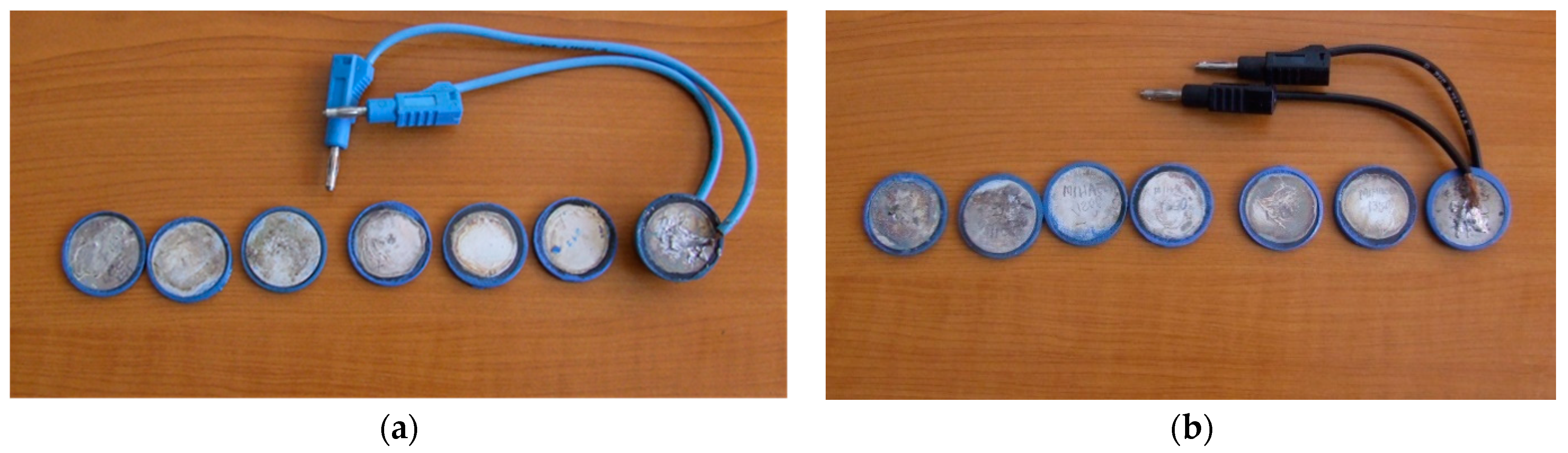
The varistors used, sintered at a pressure of 500 kgf/cm2, were:
with 2 additive oxides, 7 varistors sintered at 1100 °C, 1150 °C, 1200 °C, 1250 °C, 1300 °C, 1350 °C, 1400 °C (
Figure 2a);
with 5 additive oxides, 7 varistors sintered at 1100 °C, 1150 °C, 1200 °C, 1250 °C, 1300 °C, 1350 °C, 1400 °C (
Figure 2b);
With these varistors, the tracing of the current voltage characteristics for each of them, as well as the plot of the variance of the non-linear coefficient, will be made.
These properties are considered as essential for the characterization of the varistor material. The purpose of the whole approach was to identify the influence of temperature on the best material considered.
Due to the size of the test apparatus and equipment with the LAPLACE L.G.E.T. Laboratory, the authors decided to manufacture and test only low-voltage disc varistors, the cylindrical ones for high voltage being more difficult to test. Ultimately, they were interested in all material properties, which are not too highly influenced by the size of the varistor. All tests were performed using the apparatus described above in accordance with standardized test norms and procedures.
We used varistors with a final diameter of 30 mm (without insulation) and the final thickness (height) of approx. 3 mm. These varistors were made at L.G.E.Toulouse, using the process briefly described before. We tried to maintain the same height by offsetting with approx. 5–10% (addition of additional mixing material) for varistors that are sintered at over 1250 degrees Celsius.
In each photo, one of the varistors is bonded to the connecting cables, which connect it to the polarization test facility.
All these varistors have been crafted, including metallic deposition on both sides as well as lateral coating with blue epoxy resin. On them you can see the sintering temperature values.
We noticed that if we did not know their manufacturing process, all these 14 varistors would be similar.
4.1. Mass Losses
The problem of mass losses (through the decomposition and vaporization of some components) remains an important aspect for the metal oxide based varistor manufacturing technology, especially when manufactured on higher temperatures [
23].
The actual masses of the mixture were detailed in the previous chapters, as being the additional initial amount to be added to compensate for the losses.
We notice a constant difference of approx. 5–7% between the mass losses of the material with 2 additive oxides and those of the material with 5 additive oxides for the reasons described above. This feature should be considered in the case of serial production of varistors with 5 additive oxides, especially where it will be necessary to make a sintering mixture somewhat more voluminous than it should be.
In
Figure 3 we present the graph of mass losses as a result of exposure of varistor material to different sintering temperatures. We note that the worst-case scenario is encountered with 5 additive oxides due to a more pronounced chemical instability.
Figure 3a presents mass losses function of the sintering temperature for a 3 mm height varistor both for 2 and 5 oxides.
Figure 3b presents mass losses function of varistor height, for the 5 oxides materials only (which has a risk of degradation at high temperatures), having sintering temperatures as a parameter.
For the sintering temperature considered (1300 degrees Celsius) we find the previous values for the height of 3 mm, corresponding to losses of approx. 11–12%, which are quite significant.
We observe an almost linear dependence of the increase of the losses on the final thickness of the varistor, as the varistor is thicker (higher), the mass losses are reduced.
At the value of about 5 mm thick, the losses reach a saturation point below which they can no longer be reduced, regardless of the increase in the thickness of the varistor. This aspect is useful in the construction of varistors for high voltage fields.
In the case of thin varistors, designed to operate at low voltages, the mass losses are high, therefore, they must be carefully considered so as not to endanger the other properties of the final varistor. From a physicochemical point of view, extra additive oxides are responsible for additional mass losses which form various stable or unstable chemical structures that decompose or volatilize at high temperatures [
24].
Clearly, as the sintering temperature of the mixture is higher, the mass losses increase, therefore, the temperature of approx 1300 degrees is a good reference for the sintering process. This must be determined by further measurements.
Measurements have been reported for the initial mass of the mixture, the percentages to be lost should be added in the form of additional mass percentage of the final mixture, even if not all the oxides in the mixture are responsible for this loss, thereby accidentally making their concentration possible (compensation for loss through percent initial mix).
So, a first conclusion is that the optimal sintering temperature is around 1300 degrees Celsius.
This will be checked, especially in the case of varistors with 5 additive oxides. The next set of measurements will only consider the electrical properties of the 5 oxides additive material.
It will try to characterize the material in terms of electrical properties in order to formulate some conclusions regarding its efficiency from the point of view of the electric power.
4.2. Main Parameters for Material Assessment
The most important measurement carried out in order to assess the performances of the varistor material is dedicated to the current-voltage characteristic. All major parameters of the varistor are computed starting from this set of measurements [
8].
The principle of the method consists in measuring the varistor current at different values of the polarization voltage. The applied tensions are continuous. The measured currents are very low, which implies the use of extremely precise instruments, according to specific standards. The varistor is mounted connected by wires, not electrodes, to avoid their influence on the varistor.
Figure 4 presents the equipment used for this type of measurements.
Figure 4a presents the electrical schema of the installation and
Figure 4b presents a general photo, as it is placed at the LAPLACE Laboratory in Toulouse.
From the current-voltage characteristics, we can assess some major parameters for that varistor (or for the varistor material):
The leakage current is the current measured at the nominal voltage Un (or field intensity En), (below 1 mA at medium and high voltage). It is known as the If flow (or the current density Jf).
Varistor (or equipment) threshold voltage Us, one of the reference quantities, which is conventionally measured at a current density of 1 mA/cm2, or to simplify the measurements at a current of 1 mA. Also, for simplicity, we will refer directly to voltage and current, not to field strength and current density.
The non-linearity coefficient α, which reflects the electrical properties expected to be provided by the varistor. The higher the value of this exponent, the more the varistor protection characteristic can be said to approach the ideal one. The nonlinearity exponent is determined relatively simply by observing that it represents the slope of the characteristic I (U) for the non-linear area in logarithmic coordinates. The above relation is the equation of a straight line in which α is the slope of the straight line. As the right is determined by two points, we will consider two points on the characteristic, the coordinates (I1, U1) and (I2, U2), from where a is determined.
Conventionally, the two points of the characteristic required to determine α are chosen for current densities J = 1 and 10 mA/cm2. To simplify the measurements, we considered for this determination the currents of 1 and 10 mA.
4.3. Influence of the Sintering Temperature on Varistors’ Behaviour
We will try to characterize the material in terms of electrical properties in order to formulate some conclusions about its efficiency from the point of view of the electric power.
For measurements, the same 30 mm diameter varistors, the thickness of which was 3 mm, were used for the 230 volts AC voltage domestic applications.
With these varistors, the tracing of the current voltage characteristics for each of them, as well as the plot of the variance of the non-linear coefficient, will be performed.
These properties are considered as essential for the characterization of the varistor material. The purpose of the whole approach was to identify the influence of sintering temperature on the new material.
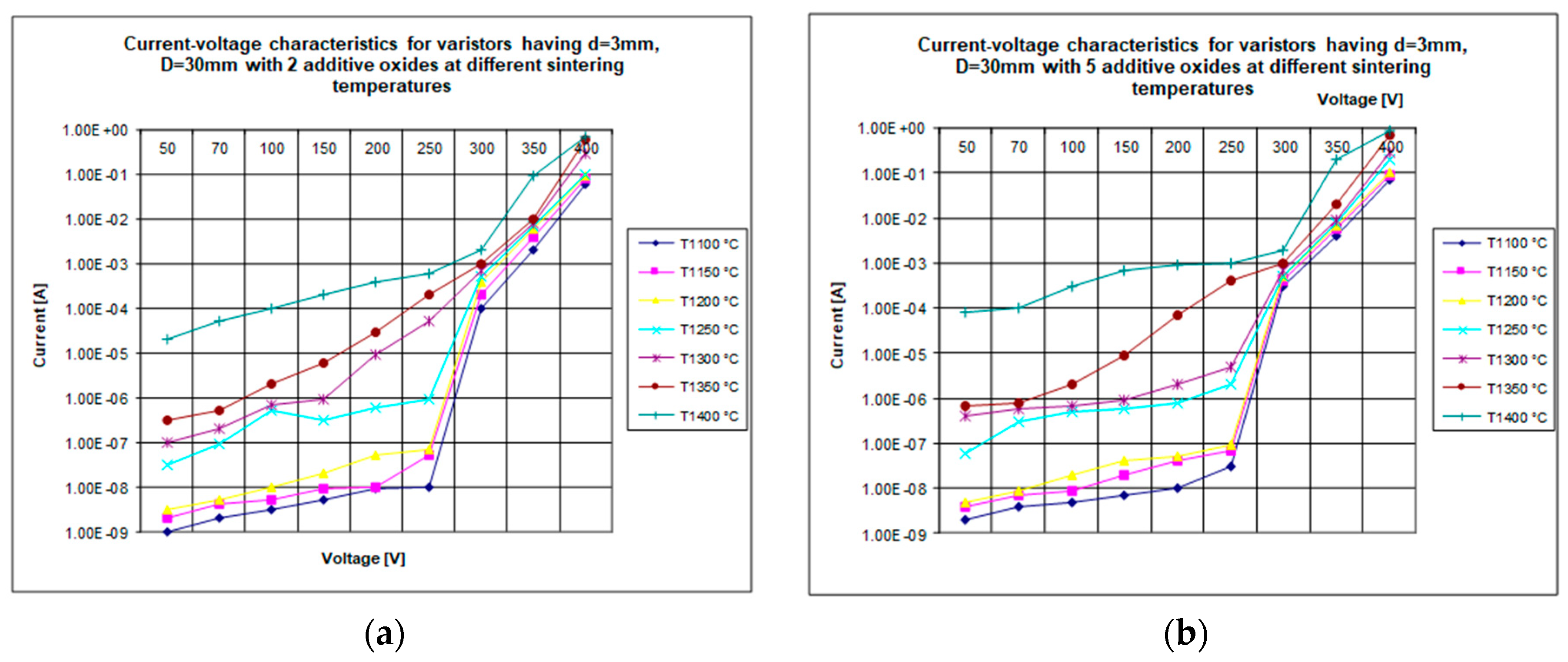
The tests were made between 50 and 400 V, DC, knowing that the opening voltage of these varistors is around 300 VDC.
Figure 5a will present the current-voltage characteristic for the seven varistors sintered at different temperatures, having two additive oxides.
Figure 5b will present the same characteristics, obtained for the seven varistors having five additive oxides.
Analyzing the measurements synthesized in
Figure 5a,b, we can formulate the following observations:
For varistors sintered between 1300 and 1400 degrees Celsius, the current-voltage characteristic is highly placed, due to the sensitivity of sintered material at high temperatures;
There is an upward movement of the current-voltage characteristics with the increase of the sintering temperature, which prevents an increase in the sensitivity of these materials, which may be beneficial in principle, but can lead to an unwarranted varistor heating;
We note that between the characteristics of the sintered materials at 1100 degrees Celsius and those at 1400 degrees Celsius there is an enormous distance of 4 orders of magnitude, the distance that is reduced to the final after the opening of the varistor at around 300 VDC. This must be considered only if we want to rise the varistor sensitivity;
We find that the varistor opening voltage is around 300–315 V when the current reaches a value of about 1 mA. This confirms the proper dimensioning of these varistors;
After opening, the behavior of the varistors is somewhat similar, the protection function being ensured, regardless of the temperature at which the varistors were sintered;
The features are in rough form, not interpolated, precisely to show the real variation of the measured parameters;
The optimum sintering temperature, in terms of opening voltage, remains around 1300 degrees Celsius, which gives a slight sensitivity to varistors, but does not endanger the safety of their operation, in a range between 1250 °C and 1350 °C.
The 2-oxide varistors compared to the 5-oxide additive varistors, have a slight descent of all the characteristics, which indeed confirms the existence of slightly lower electric performances;
Even though this material, with 2 additive oxides, is of inferior quality and in a raw form, it can be successfully used in the structure of varistors designed to operate at medium and high voltage, where the sensitivity to voltages below the opening value does not matter a lot.
Therefore, the characterization of varistor materials must be done in both situations, since each material can be useful in a dedicated application, without classifying certain combinations as unnecessarily.
Figure 6a will present the current-voltage characteristic for the seven varistors sintered at different temperatures, having two additive oxides.
Figure 6b will present the same characteristics, obtained for the seven varistors having five additive oxides.
By analyzing the measurements synthesized in the graph in
Figure 6, we can formulate the following conclusions:
All homologous characteristics of the 2 additive oxides are below the characteristics of the more elaborate material, with 5 additive oxides, which was, in a certain way, predictable. However, the difference in nonlinearity performances is not so pronounced, with an average of approx. 2–3 units;
For sintered varistors between 1300 and 1400 degrees Celsius, the nonlinearity coefficient characteristic is high due to the sensitivity of sintered material at high temperatures (due to the previous set of conclusions, we keep the same temperature range, in order to obtain a precise and clear recommended value);
Non-linearity increases significantly around the opening voltage (about 315 VDC) and has a maximum around 430–450 VDC for all varistors;
There is an upward movement of the nonlinearity coefficient characteristics with the increase in the sintering temperature, which prevents an increase in the sensitivity of these materials, which may be beneficial in principle, but can lead to an unwarranted heating of the varistor;
The value of this maximum ranges from approx. 23 to approx. 45, with a large dispersion for the two temperatures;
After the maximum, the nonlinearity decreases fast, until it reaches values of 10–15;
These values remain stabilized, regardless of the increase in tension;
Therefore, the maximum of nonlinearity remains around the varistor opening voltage;
After opening, the behavior of the varistors is somewhat similar, with the protection function being ensured regardless of the temperature at which the varistors were sintered;
The non-linearity is low and close to the value for low voltages, below the opening;
The optimum sintering temperature, from the point of view of the opening voltage, remains around 1300 degrees Celsius, which gives a slight sensitivity to varistors but does not jeopardize the safety in their operation, amid a non-linearity of over 40, which is perfect in exploitation (the same temperature as in previous case).
In order to make a complete comparison between the two materials without unnecessarily complicating the graphs, we will make a comparison between two homologous varistors, sintered at 1300 degrees Celsius, one having two additive oxides, the other five having additive oxides.
This study will consider the current-voltage characteristics and the variation of the non-linearity coefficient, the main monitored quantities in the case of general-purpose varistors.
In
Figure 7a, the comparative current-voltage characteristics obtained by performing these tests, are presented for homologous varistor materials sintered at 1300 degrees Celsius. Tests were made between 10 and 300 V, in DC, assuming that the opening voltage of these varistors is around 300 VDC. The varistors have not been placed in the opening situation, for better characterizing their sensitive zone, rather than the conduction area.
The average diameter of the ZnO granules has a great importance for the varistor manufacturer and user because it sets on the UN threshold tension (opening voltage). A ZnO based varistor is made up of granules having different sizes. Therefore, there will be a preferential way for passing the current on the minimum resistance path, crossing the ZnO granules having the smallest electrical resistance. The 5-oxide additive material limits the diameter of the granules, and therefore increases the sensitivity of the varistor.
We used the same varistors (2 pieces) having the final diameter of 30 mm (without insulation) and the final thickness (height) of approx. 3 mm. These varistors were made using the technique described before.
This comparison is necessary because it better highlights the applicability of the two materials.
Figure 8a presents the influence of the sintering temperature on the I
F (the flow/leakage current), measured at a voltage of 320 VDC, is shown, rated as similar as the peak voltage value in AC regime.
Figure 8b describes the influence of the sintering temperature on the U
D (the opening voltage), measured for a 1 mA in DC regime.
Analyzing the measurements synthesized in
Figure 8a, we can formulate the following conclusions:
For varistors sintered between 1100 and 1250 degrees Celsius, the leakage current is approximately the same regardless of the number of oxides of additives;
For varistors sintered between 1300 and 1400 degrees Celsius, the leakage current begins to increase, reaching significant values for those obtained at 1400 degrees Celsius, which prevents an increase in the sensitivity of these materials. It could be useful in principle, but leads to an unwarranted varistor heating;
This increase of the permanent drainage current is aggravated in the situation of the varistors with 5 additive oxides, which obviously become more sensitive, a process which is not necessarily beneficial;
The optimum sintering temperature, from the point of view of the drainage current remains approx. 1300 degrees Celsius, which gives a slight sensitivity to varistors but does not endanger the safety of their operation.
Sintered at approx. 1300 degrees Celsius, varistor material with 5 oxide additives is slightly more sensitive.
Analyzing the measurements synthesized in
Figure 8b, we can formulate the following conclusions:
For varistors sintered between 1250 and 1400 degrees Celsius, the opening voltage is approximately the same regardless of the number of oxides of additives;
For varistors sintered from 1250 to 1400 degrees Celsius, the opening voltage begins to decrease, reaching low values for those obtained at 1400 degrees Celsius, which prevents an increase in the sensitivity of these material. This is not always seen as an advantage;
This decrease in permanent opening voltage is aggravated at varistors having 5 additive oxides, which clearly become more sensitive, a trend that is not necessarily wanted;
In this case, the optimal sintering temperature, in terms of opening voltage, is approx. 1300 degrees Celsius, which gives a slight sensitivity to varistors but does not endanger the safety of their operation.
Sintered at approx. 1300 degrees Celsius and even more, varistor material with 5 oxide additives is slightly more sensitive.
5. New Research about the Sintering Pressure of Varistor Materials
The other important parameter of the sintering process is the sintering pressure.
From a physicochemical point of view, a higher sintering pressure provides a better material. But high-pressure sintering installations are extremely costly. Therefore, the influence of the sintering pressure on the varistor material must be checked by measurements.
At the crystalline structure of the varistor, the high sintering pressure causes a reduction in the size of the granules and the intergranular junctions, which leads to increased sensitivity of the varistor material, which is not always desirable [
8].
Varistors so far have been sintered at a pressure of 500 kgf/cm2. Through the above-described installation, a sintering of the varistors at a doubled pressure of 1000 kgf/cm2, which is the maximum possible of the installation, was also attempted. The sintering temperature is what is considered optimal from previous measurements, i.e., 1300 °C.
Even if the sintering pressure is doubled, the mass losses are about the same, being affected only by the volatilization of some compounds in the atmosphere (by temperature)). No variation in density is registered.
Four varistors having d = 3 mm and D = 30 mm were used as follows:
Two varistors of material with two additive oxides, sintered at 500 kgf/cm2 (one of the previous ones) and 1000 kgf/cm2 (new one), respectively;
Two varistors of material with five additive oxides sintered at 500 kgf/cm2 (one of the previous ones) and 1000 kgf/cm2 (new one) respectively;
Figure 9a presents the family of current-voltage characteristics obtained by these tests, having the sintering pressure as a parameter. The tests were made between 50 and 400 V in DC regime, assuming that the opening voltage of these varistors is around 300 VDC.
Figure 9b describes the family of characteristics for the nonlinearity coefficient according to the voltage obtained by these tests, having as parameters the two materials with 2 and 5 additive oxides, with two sintering pressures, made as 500 and 1000 kgf/cm
2 respectively. The tests were made between 50 and 600 V in DC regime, presuming that the opening voltage of these varistors is around 300 VDC. The varistors are those already made and subjected to standard tests using the technique described before.
Analyzing the measurements synthesized in
Figure 9a, we can formulate the following conclusions:
For this sintering temperature, the four curves are very close, practically we cannot opt for one or the other in terms of some slightly better electric performances;
Practically, the sintering pressure has no visible and spectacular effect on the electrical performance of these varistors;
For all varistors sintered at 1300 degrees Celsius, with 2 or 5 oxides at different pressures, the current-voltage characteristic is high due to the sensitivity of sintered material at high temperatures;
Among the characteristics of materials with 2 and 5 oxides additives, there are very little differences, which makes them similar in quality from the point of view of tension;
We find that the previous statement, namely that the varistor opening voltage is around 300–315 V when the current reaches a value of about 1 mA, confirms their proper dimensioning, regardless of the number of oxides of additives taken in calculation and considered in sintering pressure;
After opening, the behavior of the varistors is somewhat similar, the protection function being ensured, regardless of the pressure at which varistors have been sintered;
The features are in rough form, not interpolated, precisely to show the real variation of the measured parameters;
The optimum sintering pressure, in terms of opening voltage, remains about. 500 kgf/cm2, because it can also be made on simpler installations like construction, reducing the manufacturing costs of varistors. The price difference of a high-pressure installation (apparatus, molds, etc.) is not amortized by the price difference that may be required based on a difference in electrical properties.
Analyzing the measurements synthesized in
Figure 9b, we can formulate the following conclusions:
The difference of nonlinearity performance is also quite pronounced in this case;
The material with 5 oxides of additives also reaches quite pronounced values of nonlinearity at about 43 immediately after opening, which is very useful for their use in low voltage/domestic applications and 230 VAC.
The increase in the sintering pressure leads to the upward movement of the nonlinearity of varistors, regardless of the number of oxides of the constituent additives;
The characteristics for two oxides or for five additive oxides are relatively close, from where we confirmed the hypothesis that the pressure does not have an important role in determining the electrical properties of the material;
The value of this maximum ranges from approx. 23 at approx. 45, with a large dispersion for the two materials;
After the maximum, the nonlinearity decreases until it reaches values of 10–15;
These values remain stabilized, regardless of the increase in tension;
Therefore, the maximum of non-linearity remains around the varistor opening voltage, especially in the case of materials with 5 additive oxides and sintered at a higher pressure;
The optimum sintering pressure, in terms of opening voltage, remains about. 500 kgf/cm2, because it can also be made on simpler installations like construction, reducing the manufacturing costs of varistors. The price difference of a high-pressure installation (apparatus, molds, etc.) is not economically justified and covered by the price difference that may be required on sale, based on a small difference in electrical properties. This conclusion was also verified by the previous set of measurements.
6. Discussion
Most of the discussions on this article were carried out after presenting the results.
Concerning the composition and the manufacturing process of the varistors, the following aspects must be emphasized:
In the situation of thin varistors designed to function at low voltages, the mass losses are high, therefore, they must be considered very carefully so as not to endanger the other properties of the final varistor;
These mass losses, which must be compensated by the addition of an additional initial mixture, can reach up to 10–15% in the case of 5 additive oxide varistors;
Any improvement in manufacturing technology produces an upward movement of nonlinearity coefficient and current-voltage characteristics, which prevents an increase in the sensitivity of these materials. This may be beneficial in principle, but can lead to an unwarranted varistor heating;
The 5 additive oxide material is more electrically sensitive than the one based on 2 additive oxides, especially at low voltages below the opening threshold voltage, making this material suitable for applications in the field of electronics or in the 230 VAC area, while the more robust and rigid 2-oxide can be used for medium and high voltage;
The optimal sintering temperature for both varistor compositions remains verified and stabilized around 1250 °C–1300 °C, as a reasonable current-voltage characteristic is obtained here, without causing an unwarranted increase in varistor sensitivity, which could create subsequent thermal runout or unstable operation;
The optimal sintering pressure, in terms of the opening tension and nonlinearity coefficient, remains about 500 kgf/cm2, because it can also be made on simpler installations, reducing the manufacturing costs of varistors. The price difference of a high-pressure installation (apparatus, molds, etc.) is not justified and covered by the price difference that may be required based on a difference in electrical properties. This conclusion was also verified by the previous set of measurements;
After opening, the behavior of the varistors is somewhat similar, the protection function being ensured, regardless of the voltage at which the varistors are exposed, the initial mixing or the parameters of the sintering cycle;
Due to the equipment existing at the LAPLACE L.G.E.T. Laboratories, we performed all tests on low voltage disc varistors, the high voltage cylindrical ones being more difficult to test;
The material properties were mostly taken in account, which are not too much influenced by the size of the varistor piece made of that material. All tests were performed using the apparatus described above are in accordance with standardized test norms and procedures.
7. Conclusions
This article covers a short study on the influence of some varistors manufacturing issues (sintering temperature and pressure) on their electrical parameters, both for two additive oxide varistors and for those with five additive oxides.
The measurements aimed to establish chemically reproducible compositions that were effective and safe in terms of the electrical properties of the material.
These chemical compositions are new and original, made in order to provide a simple variant of a varistor manufacture and easily reproduced by any manufacturer of such electronic power devices.
In the daily practice of varistors, there is no mathematical model that leads to a certain varistor manufacturing dedicated technology with certain properties. The physicochemical mechanisms that lead to the formation of the crystalline structure of the varistor are not elucidated at present, and the theories of silicate chemistry or the physics of solid bodies fail to explain the process of sintering of varistors based on oxide mixtures metal in detail.
Consequently, the serial production of these semiconductor-based electronic power devices is a purely empirical activity based on simple research, which is related to the optimization of the main parameters of the manufacturing process through experiments and successive tests, sometimes combined with elements solid physics and silicate compounds technology.
This domain is a cross-border, transdisciplinary, but interdisciplinary area, as far as all these elements are found.
Manufacturing varistors remains, consequently, a succession of more empirical operations. From the engineering point of view, this empiricism can be useful until an efficient technology is developed, and the scientific models will be further developed. This approach is defining the entire approach of this paper, without affecting the scientific quality of the work. Improving the electrical properties of varistors can be done both by optimizing the concentration of each constituent and by altering the parameters of the thermal sintering cycle.


