Droplet Characteristics of Rotating Packed Bed in H2S Absorption: A Computational Fluid Dynamics Analysis

School of Chemistry and Chemical Engineering, Southwest Petroleum University, Chengdu 610500, China
*
Authors to whom correspondence should be addressed.
Processes 2019, 7(10), 724; https://0-doi-org.brum.beds.ac.uk/10.3390/pr7100724
Submission received: 7 August 2019
/
Revised: 5 October 2019
/
Accepted: 8 October 2019
/
Published: 11 October 2019
(This article belongs to the Special Issue CFD Modeling of Complex Chemical Processes: Multiscale and Multiphysics Challenges)
Abstract
:Rotating packed bed (RPB) has been demonstrated as a significant and emerging technology to be applied in natural gas desulfurization. However, droplet characteristics and principle in H2S selective absorption with N-methyldiethanolamine (MDEA) solution have seldom been fully investigated by experimental method. Therefore, a 3D Eulerian–Lagrangian approach has been established to investigate the droplet characteristics. The discrete phase model (DPM) is implemented to track the behavior of droplets, meanwhile the collision model and breakup model are employed to describe the coalescence and breakup of droplets. The simulation results indicate that rotating speed and radial position have a dominant impact on droplet velocity, average residence time and average diameter rather than initial droplet velocity. A short residence time of 0.039–0.085 s is credited in this study for faster mass transfer and reaction rate in RPB. The average droplet diameter decreases when the initial droplet velocity and rotating speed enhances. Restriction of minimum droplet diameter for it to be broken and an appropriate rotating speed have also been elaborated. Additional correlations on droplet velocity and diameter have been obtained mainly considering the rotating speed and radial position in RPB. This proposed formula leads to a much better understanding of droplet characteristics in RPB.
1. Introduction
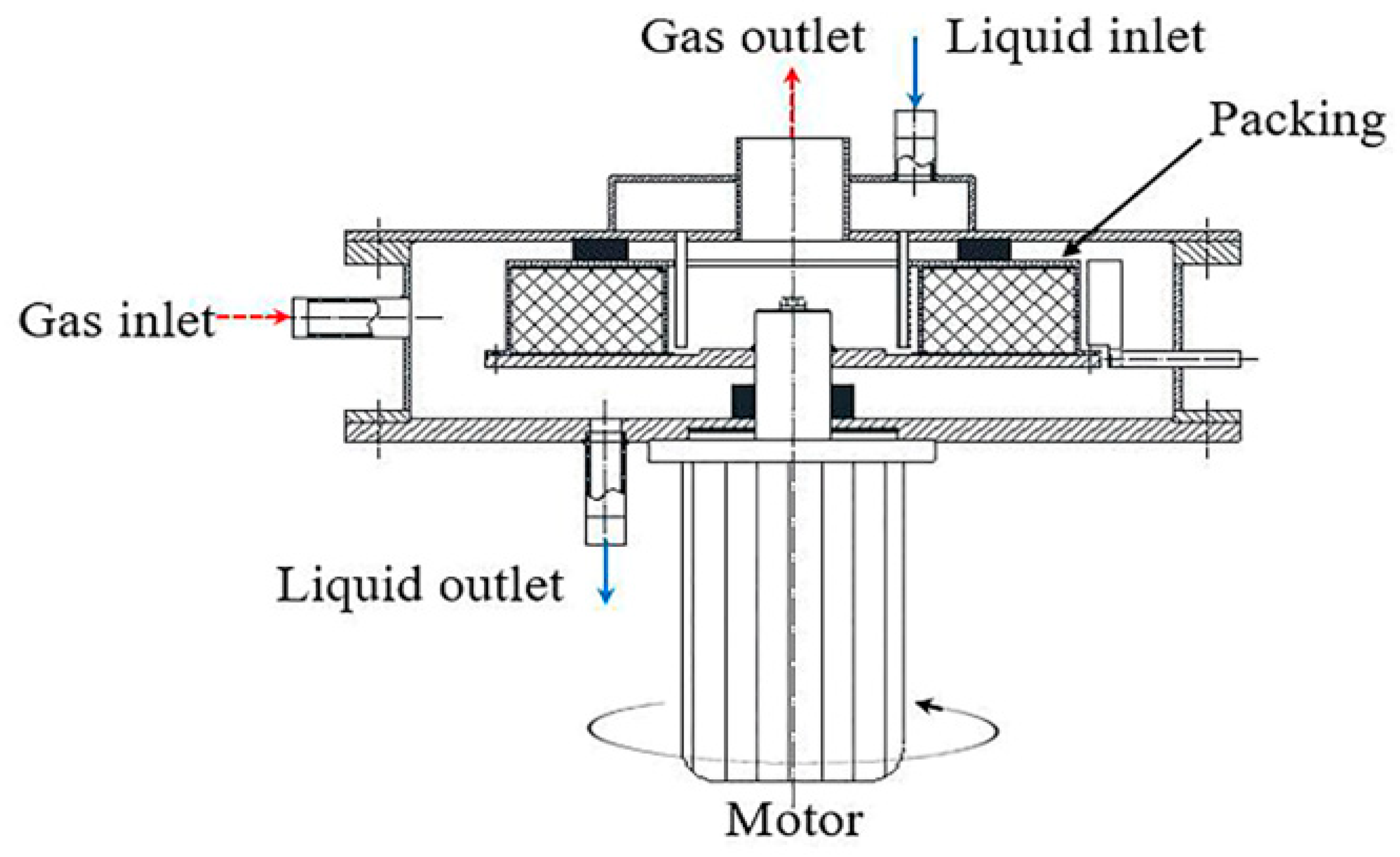
Rotating packed bed (RPB) has been demonstrated as a novel and efficient equipment in process intensification of mass transfer and reaction [1], as displayed in Figure 1. Gas phase and liquid phase contact counter-currently in the packing by centrifugal force, and the height of mass transfer unit (HTU) in RPB can dramatically decrease by 1–3 orders of magnitude compared with that in a conventional column. Therefore, RPB can evidently enhance productivity while also remarkably reducing the device size and equipment investments. RPB has been maturely applied to the traditional chemical industry [2] in processes such as distillation, absorption and extraction. It has gradually begun to play a crucial role in gas purification, especially for H2S removal in natural gas.
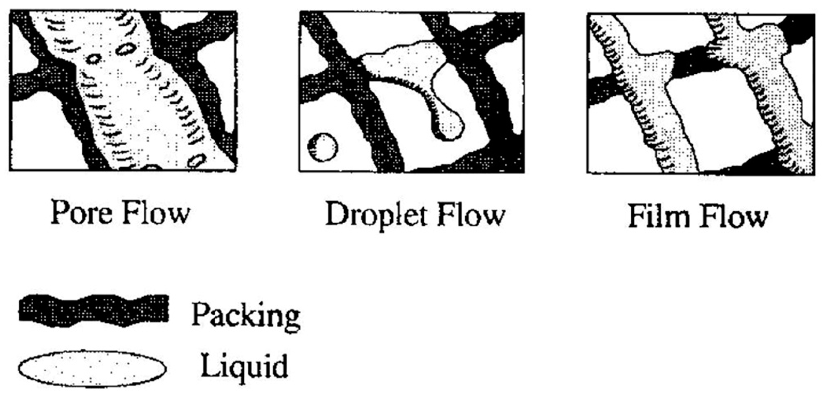
Various investigations have been carried out to reveal the gas–liquid behavior in RPB by experimental method. Burns and Ramshaw [3] exhibited a visual liquid patterns, shown in Figure 2, in the way that a video camera was arranged rotating synchronously with the packing. Liquid patterns can be distinguished into pore flow, droplet flow and film flow in different stages and positions. At a lower rotating speed, the rivulet flow was dominant while droplet flow mainly existed at a higher rotating speed. Guo [4] found that liquid impinged and deformed intensively within the initial 7–10 mm from the inner diameter and that liquid performed two states in the packing: Films on the packing surface and films flying in the gap of packing. Moreover, Li [5] investigated the effect of a various operating conditions especially for the layer numbers on the liquid patterns and drew a conclusion that the droplet was the main pattern in packing. As for recent research, Sang [6] indicated a criterion to distinguish two typical liquid patterns: Ligament flow and droplet flow.The Computational fluid dynamics is called CFD for short, which is a combination of computer and numerical techniques. The nature of CFD is that some physical phenomena can be obtained by solving related partial differential equations in computer. Due to the lower cost and visualization of process and results of CFD technology, the application of CFD has become a powerful approach to depict the liquid patterns and behaviors in RPB. Shi [7] verified that the flow patterns were varied under different rotating speeds in CFD simulation. Ouyang emphasized that a higher viscosity of liquid led a liquid line predominantly [8]. In another simulation article, Ouyang et al. pointed out that droplet diameter increased with decreasing rotating speed, liquid initial velocity and number of layers in a Rotor–Stator reactor (RSR) [9]. Conclusively, Xie [10] figured out that the collision and merging of droplets occurred between droplets and packing and that the liquid flow tended to form droplets under the influence of surface tension (larger contact angles) and high rotating speeds (1000–1500 rpm).
Aforementioned visual studies through experimental method and CFD method elaborate that typical flow pattern in RPB is liquid droplet. Although characteristics of droplets such as velocity, average residence time and average diameter exert great influence in design and improvement of RPB, there are still few studies on them. Consequently the present work investigated the influence of rotating speed, initial droplet velocity and initial droplet diameter on droplet velocity, average droplet residence time as well as average droplet diameter by CFD method. Through introducing the collision and breakup model, correlations of droplet velocity and average diameter were proposed. Additionally, a phenomenon called “end effect” in the end zone and a principle of processing intensification contributing to H2S selective absorption were also presented.
2. Simulation
2.1. Physical Model and Grid Refinement of RPB
The structure of RPB in this study is based on a pilot installation built in a natural gas purification plant, and Table 1 displays the main dimensions of RPB. It has a 24 mm height, 45 mm inner diameter and 160 mm outer diameter. Packing is regarded as a crucial part of RPB and it generally consists of uniform thickness wire, which has a 20 mm height, 48 mm inner diameter and 92 mm outer diameter.
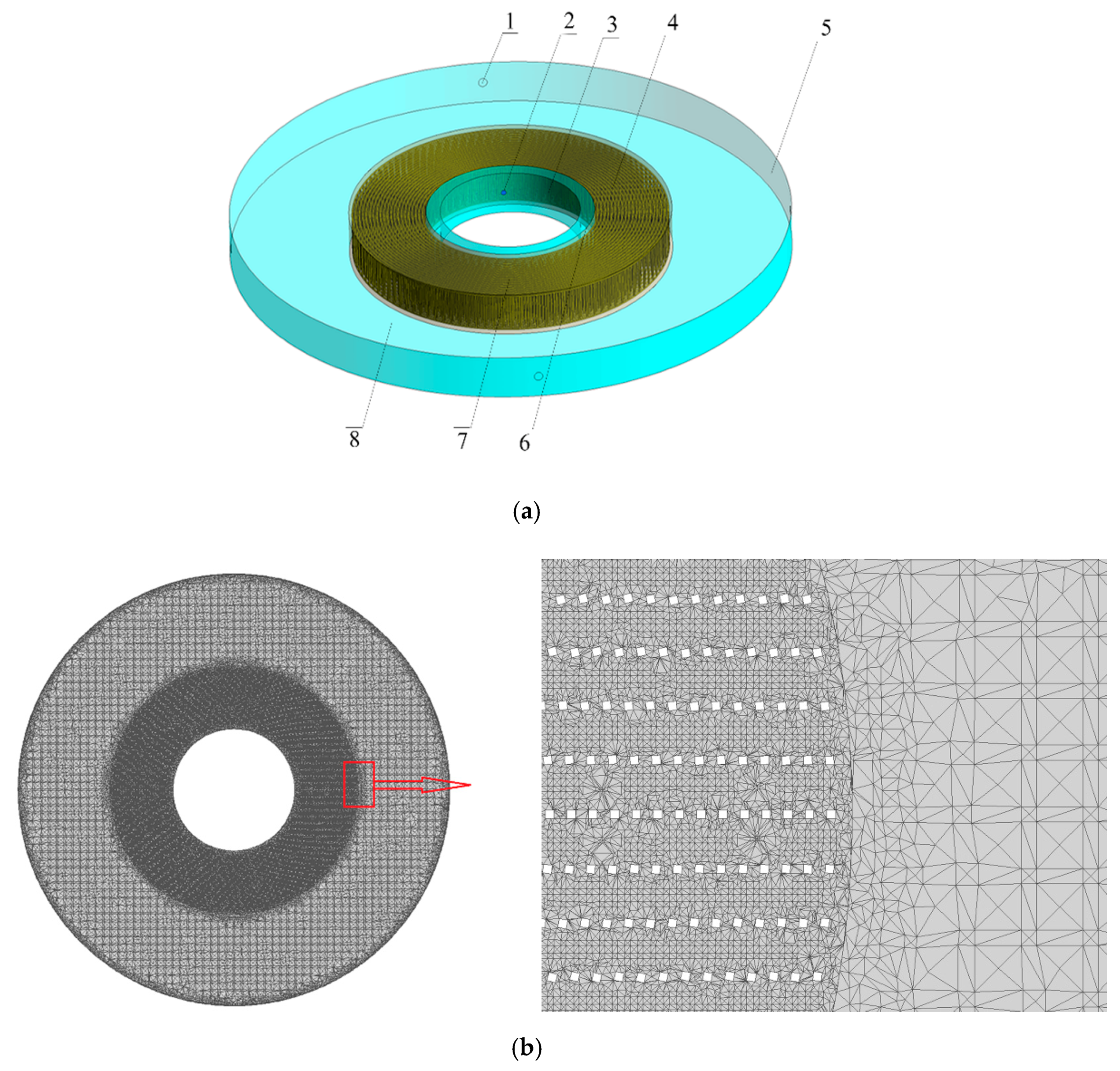
In order to make the 3D model as consistent as possible with the actual structure, there are three parts in 3D model: End zone, packing zone and cavity zone (Figure 3a). The packing zone is built with 21 concentric layers, and the foursquare obstacles model is employed to simulate the wire behavior in RPB. Consequently, the side length of each foursquare is 0.8 mm and the center distances between two foursquares in radial and tangential directions are 2 mm and 5 mm, respectively. Four annulus distributors set uniformly in the inner radius of RPB are set as liquid inlets and an outer ring is the outlet.
A computational 3D model grid is built by ICEM 19.0. In order to describe more details, a grid refinement has been made, namely different numbers of cells are meshed in different parts. At the same time, the packing zone and the end zone are meshed by tetrahedral cell, and the cavity zone is meshed by mixed cell. The meshing result is shown in Figure 3b.
2.2. Mathematical Modelling
In this study, based on an assumption that the second phase as a dispersed part occupies a low volume fraction (below 10%), the Eulerian–Lagrangian approach is used in which the natural gas is considered as a continuous phase while the MDEA solution is regarded as a discrete dispersed phase. Forces, like drag force, buoyancy force and virtual mass force, are taken into account to describe the particle force balance. A turbulence model is introduced to reflect the turbulent process when packing shears the MDEA solution intensely under high rotation speed. Models, such as Taylor analogy breakup (TAB) model and O’Rourke model, are carried out to predict the breakup and coalescence of droplets.
2.2.1. Governing Equations
The basic equations coupled in CFD models for solving mass and momentum conservation equations are listed below for an incompressible, laminar flow, non-accelerating and unsteady state process:
Mass conservation equation
Momentum conservation equation
where is the static pressure, is the fluid density, is the gravitational vector, is the molecular viscosity and is the external body force representing the interactions between the dispersed phase and the continuous phase. As for a flow in a rotating reference frame, like the rotation in RPB, the origin of the non-accelerating system is determined by a centrifugal acceleration in a rotating system, hence the governing equations of flow in a rotating reference frame are as follows:
where is the relative velocity, is the centrifugal acceleration, is the Coriolis acceleration, is the whirl velocity and is the centripetal acceleration.
Although the Navier–Stokes equation can accurately describe the mass and momentum of the laminar flow, the turbulence caused by intensive movement can evidently influence the transport process. Therefore, the turbulence model determines additional variables as time-averaged or ensemble-averaged in the modified governing equations.
2.2.2. Turbulence Model
The standard – model is presented by molecular viscosity and dynamic viscosity due to the turbulence and it is a two-equation model. It is a semi-empirical model, and the solution of the k equation allows the turbulent kinetic energy to be determined while the result of the equation can be considered relying on phenomenological considerations and empiricism.
where represents the influence of the mean velocity gradients, represents the influence of the buoyancy force, is the turbulent viscosity, is the turbulent Prandtl number for energy, is the turbulence kinetic energy and is the dissipation rate. , , , , , are the model constants and the default values are: , , , , .
2.2.3. Droplet Force Balance
In a Lagrangian reference frame, the force balance on the particle which drives the particle acceleration is due to the difference in velocity between fluid and particles as well as various influences of force, like drag force, gravity, virtual mass force and centrifugal force in RPB. Hence, a particle force balance can be written as:
Drag force
where is the drag force per unit particle mass, is the gravity per unit particle mass, is the additional acceleration term (force per unit particle mass), is the drag coefficient, is the relative Reynolds number, is the particle velocity, is the fluid velocity and is the particle density.
Virtual mass force
Forces in rotating reference frames
where is the virtual mass force, and are the forces in rotating reference frames in and directions, respectively and is the rotating speed.
2.2.4. Droplet Coalescence and Breakup Model
The coalescence model
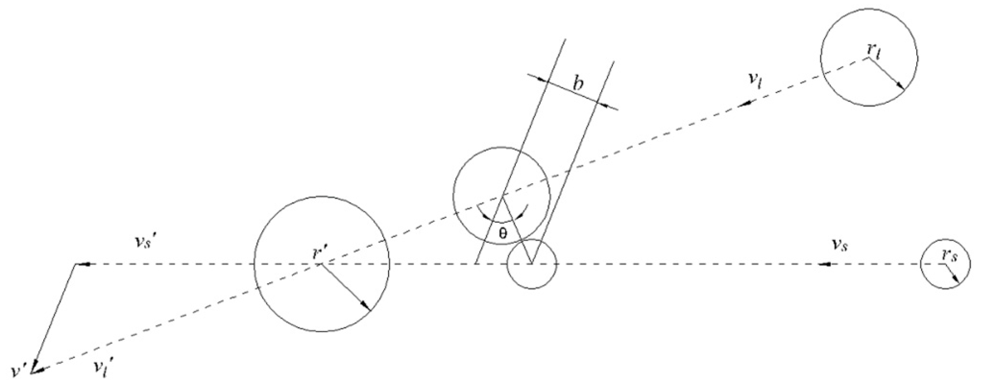
The O’Rourke model a is model based on energy balance; the droplets will coalescence once the kinetic energy cannot overcome the surface energy of a new droplet [11]. is defined as a ratio of inertial force to surface tension to quantify the collision and coalescence of droplets. Therefore, the critical offset is a function of the collisional, shown in Figure 4.
where is the Weber number, and are the velocities of large droplets and small droplets, respectively, is the arithmetic mean diameter of two droplets, and are the radii of large droplets and small droplets, respectively, and are the actual collision parameter and the critical offset of collision, respectively. If , the result of collision is coalescence, and the new velocity based on conservation of momentum and kinetic energy is calculated below:
where and are the masses of large droplets and small droplets, respectively.
Taylor Analogy Breakup (TAB) model
The TAB model governs the oscillating and distorting droplet; when the droplet oscillations grow to a critical value, the large droplet will break up into small droplets. The droplet distortion governing equation is defined as follows:
where is the displacement of the droplet, is the droplet mass, is the aerodynamic force of the droplet, is the surface tension of the droplet and is the viscous force.
where , , are dimensionless constants, , , . Setting , when and , the non-dimensional equation for droplet breakup is shown in Equation (28).
The size of droplet is determined by the energy conservation between the parent droplet and the child droplets which satisfies the Sauter distribution and the number of child droplets can be calculated by mass conservation.
2.3. Fluid Properties
MDEA aqueous solution is one of the conventional absorbents for H2S selective absorption. In this study, the gas mixture consists mainly of methane and the mass fraction of the aqueous solution is 35%. The properties of the gas and liquid used for the CFD simulations are shown in Table 2. The MDEA aqueous solution is assumed to operate at a constant temperature of 30 °C and 2 MPa, which are close to the real operation conditions for H2S selective absorption in RPB. Under these temperature and pressure conditions, the density and viscosity of the gas mixture are 15.99 kg/m3 and 1.203 × 10⁻⁵ kg/(m·s), respectively; the density and viscosity of the aqueous solution are and 1027 kg/m3 and 1.203 × 10⁻⁵ kg/(m·s), respectively.
2.4. Solution Procedure
The domain of the packing zone is defined as the moving reference frame (MFR) and the rest of RPB: End zone and cavity zone are relative to a stationary reference frame in the Fluent 19.0 software. Thus, the packing with a reflect boundary rotates in a rotating speed of 300 to 900 rpm and the wall condition with no-slip and escape boundary is set to simulate the casing of RPB. The gas inlet and outlet in RPB are set as the velocity inlet boundary and pressure outlet boundary conditions, respectively, while the liquid inlet and outlet are defined as discrete phase surface injection and trap boundary condition, respectively. The gas velocity is considered as a constant 0.5 m/s, and the droplets are injected into the RPB in this way that initial droplet velocity is specified by a range of 0.5 to 2.5 m/s, the initial droplet diameter is set to 1 to 5 mm and the number of droplets injected into the RPB is 400. Steady simulations are implemented with standard model and DPM model to investigate the droplet characteristics in RPB. The droplet discrete phase interacts with the continuous phase every five iterations and an unsteady particle tracking is applied to track the droplet trajectories individually with a time step size of 0.001 s for a maximum of 5000 steps. Drag force, gravity, virtual mass force and centrifugal force are considered in this solution and droplet coalescence and breakup models mentioned above are also introduced. The pressure–velocity coupling is resolved by SIMPLE scheme and spatial discretization methods for gradient and pressure are least squares cell-based and PRESTO, respectively. The second-order upwind scheme is employed for solving the momentum equations and turbulence equations. For the convergence absolute criteria, the residuals in mass conservation, momentum conservation and turbulence are less than 1 × 10⁻⁵. In addition, the maximum number of iterations for steady calculation is 4000 to achieve the steady state in RPB.
2.5. Grid Independence
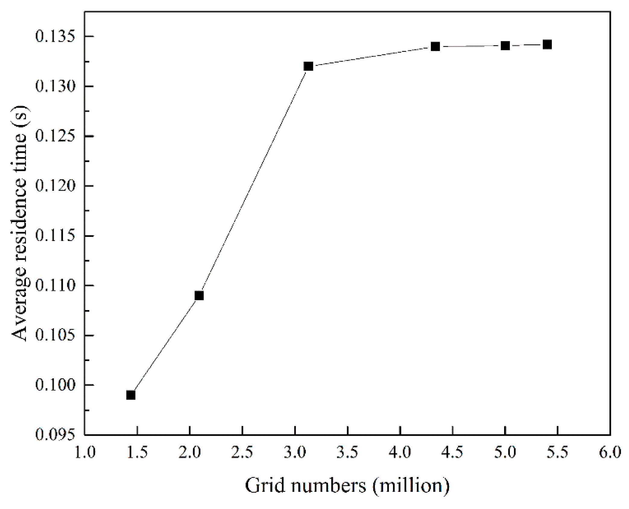
As is known, the number of grids has a great impact on the accuracy of the simulation result. Therefore, a grid independence study is performed to obtain a reasonable computational mesh. Fixing the droplet diameter of 2 mm, rotating speed of 300 rpm and initial droplet velocity of 0.5 m/s as the initial conditions and choosing the droplet average residence time as the only dependent variable, five different grids consisting of 1.4, 2.5, 3.3, 4.3 and 5 million unstructured cells have been implemented to analyze the effect of the cell on the droplet average residence time. As shown in Figure 5, the average residence time is almost same when the number of cells reaches 4.3 million, which may be considered as a responsible grid to predict droplet characteristics. Finally, the number of 4,349,428 cells is selected to investigate other simulation results while considering the computing resources and accuracy.
3. Results and Discussions
Since droplet form in RPB is the dominant liquid pattern, its characteristics such as velocity, residence time and diameter in mass transfer and reactions will play a crucial role in novel research. Therefore, a CFD simulation on droplet characteristics will demonstrate a visual flow distribution as well as significant guide for H2S selective absorption into MDEA solution in RPB.
3.1. Droplet Velocity in RPB
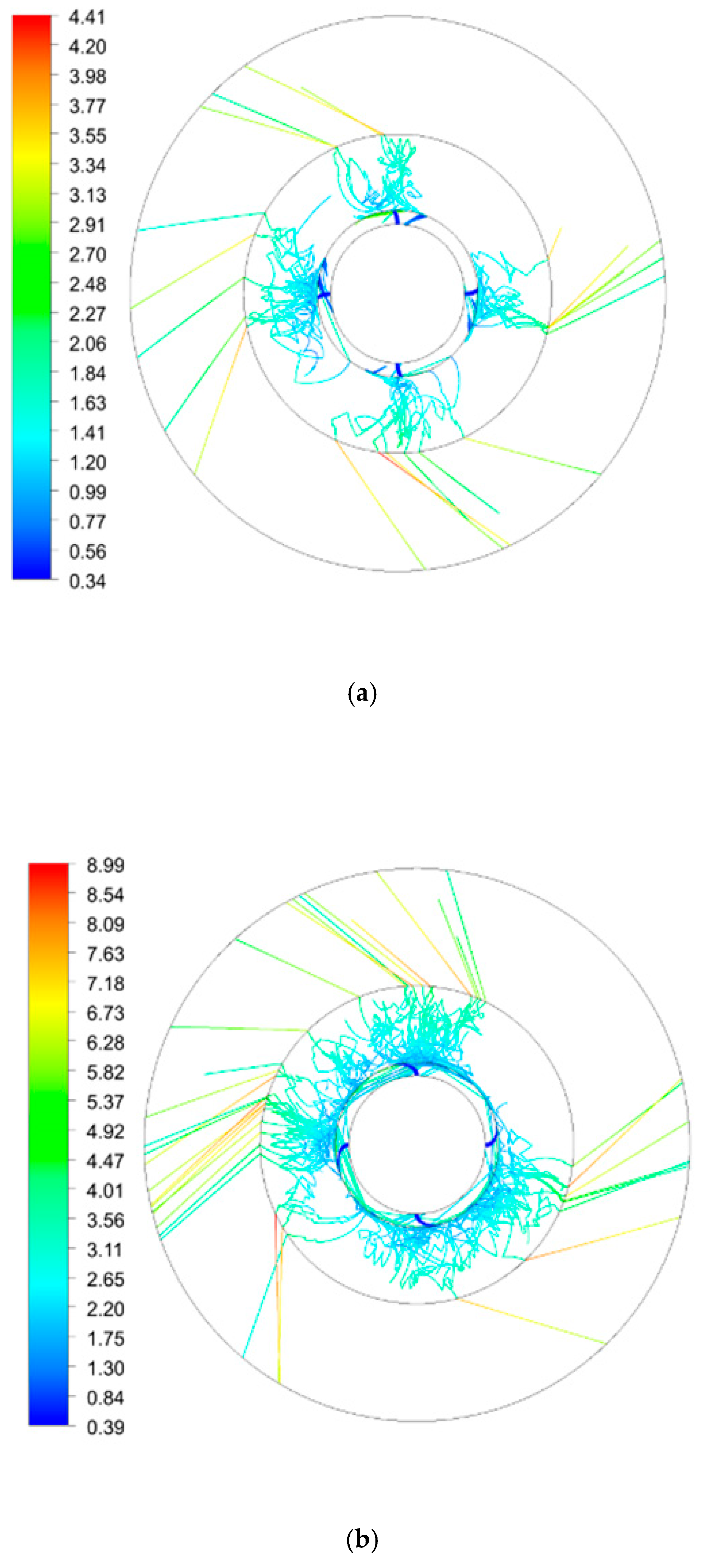
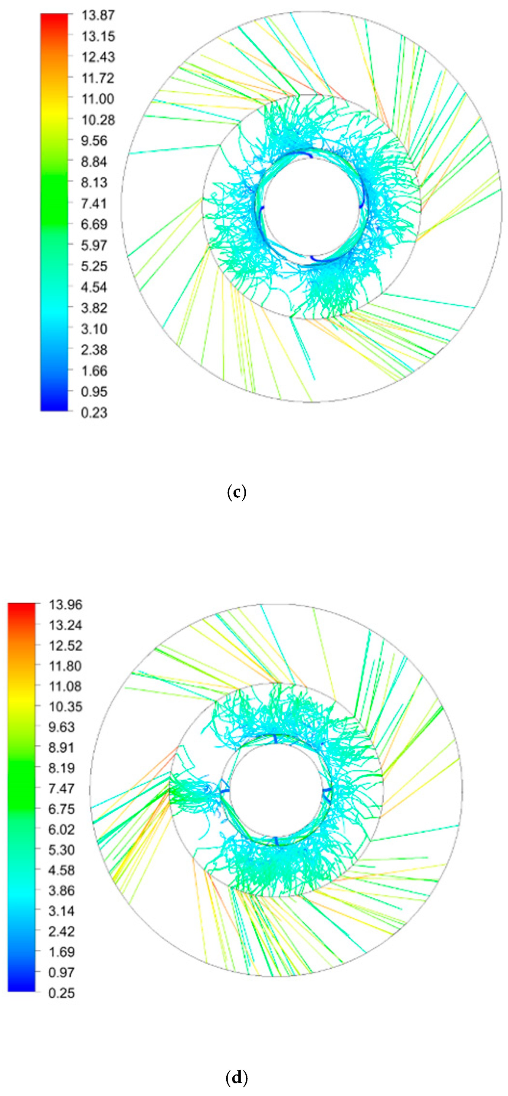
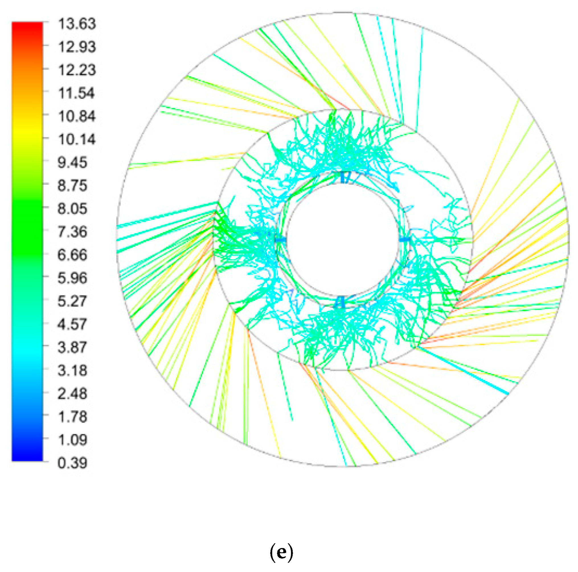
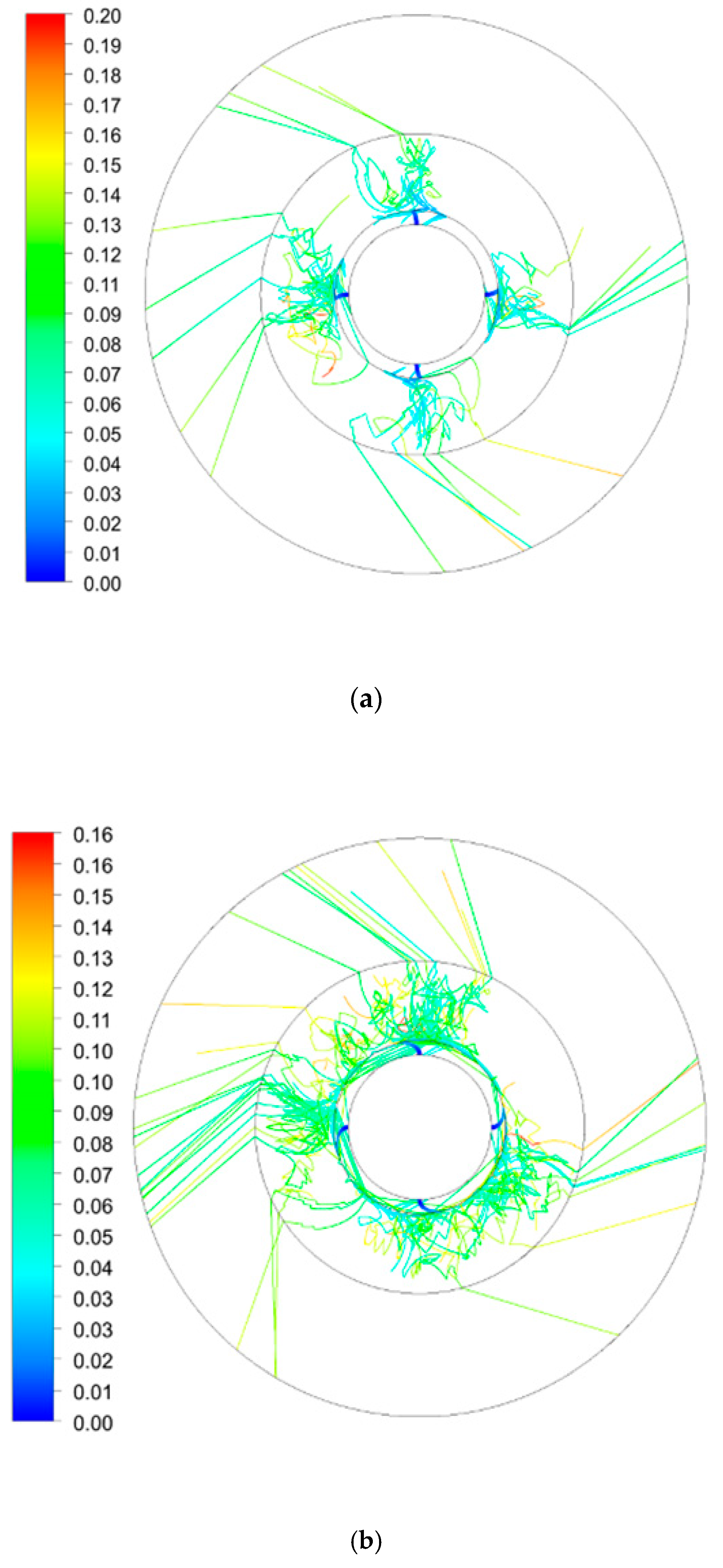
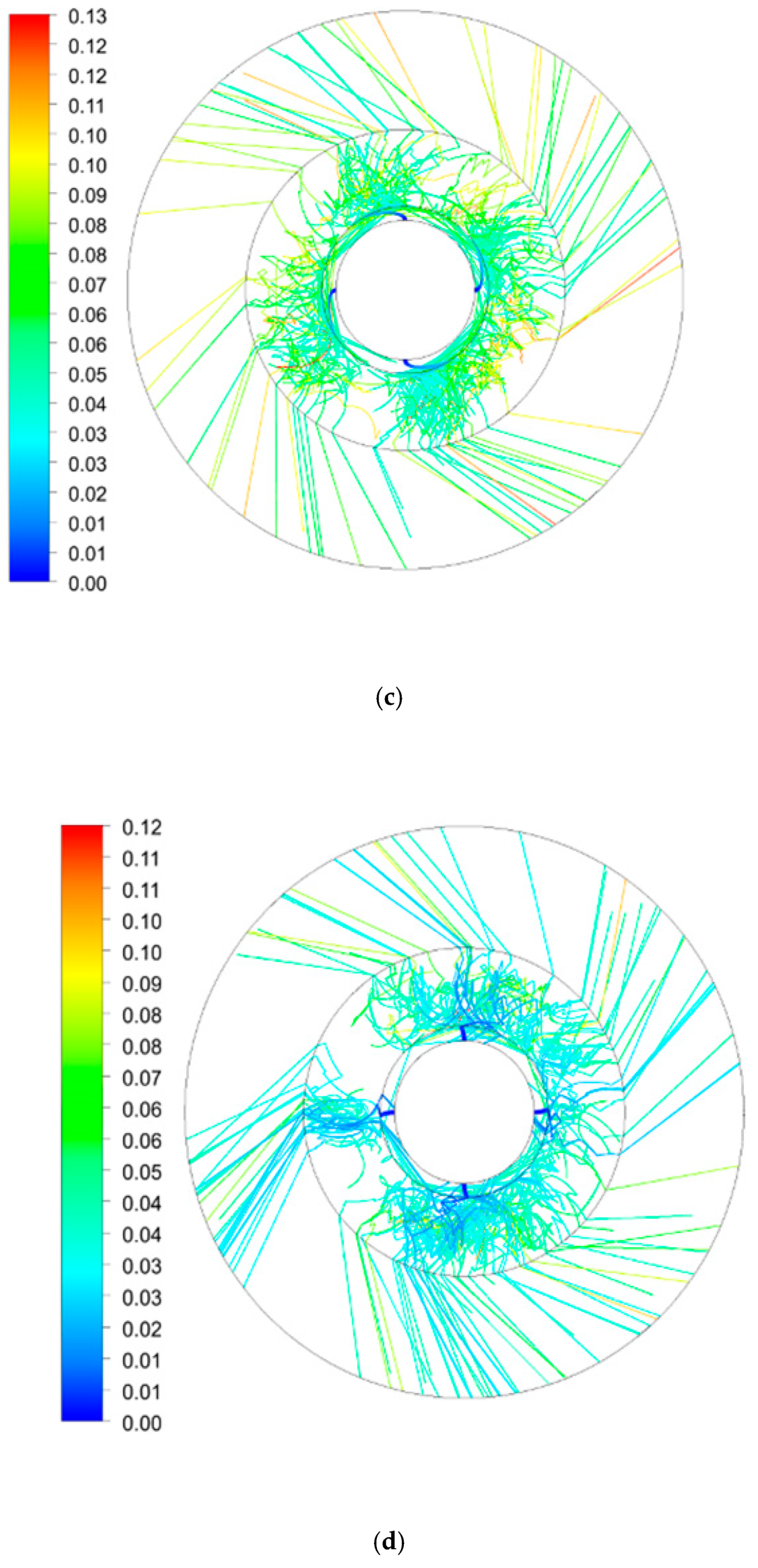
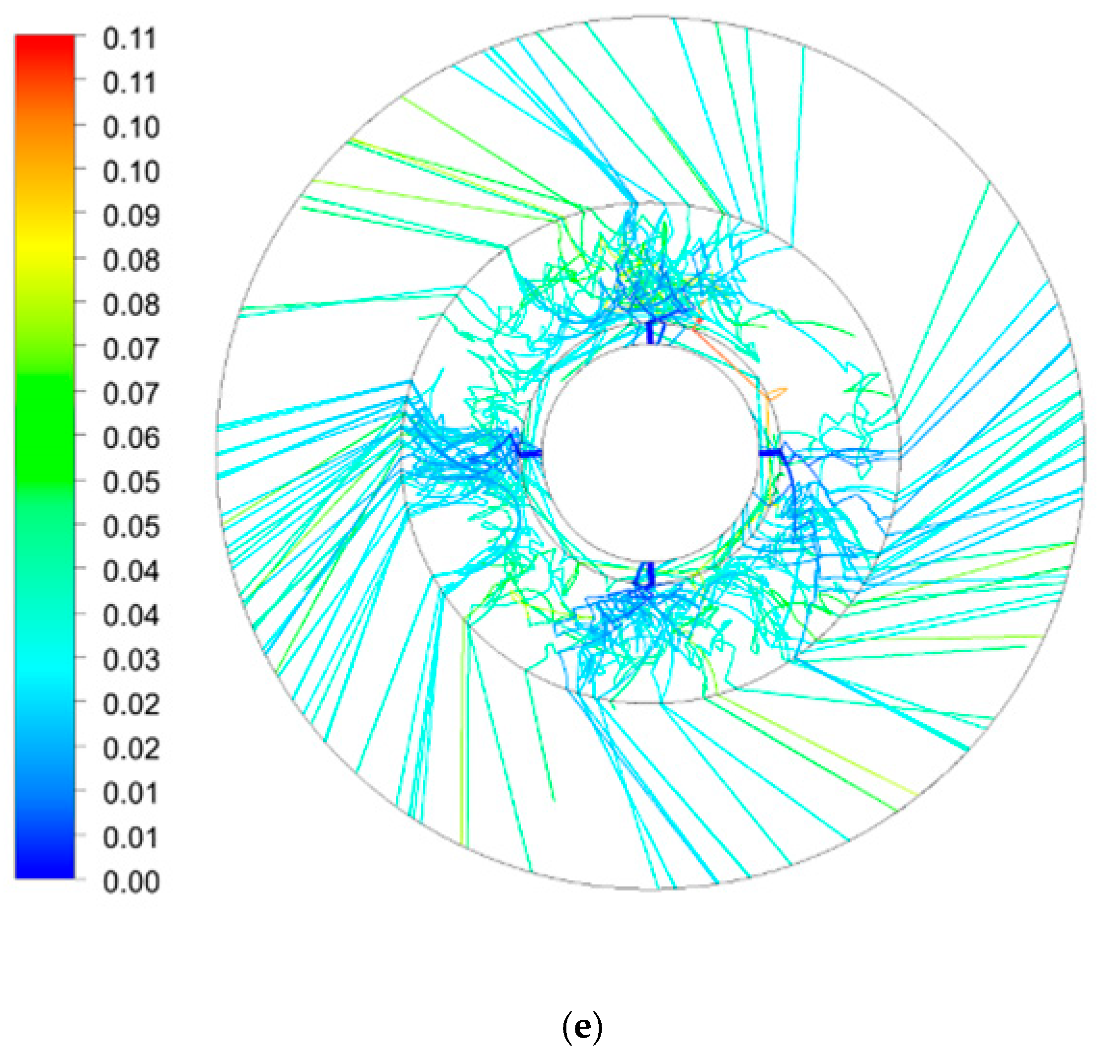
Velocity distribution, as a common and crucial characteristic of droplets, has a direct effect on residence time and diameter, therefore the velocity value and vector under various rotating speeds and initial droplet velocities are shown in Figure 6. Similarly, the velocity is distributed uniformly and symmetrically along the radial and tangential directions. The liquid is injected and dispersed uniformly into packing zone from the liquid distributor and it rapidly obtains a synchronous tangential speed as it is packing, finally liquid droplets are spun out from the outer packing zone into the cavity randomly.
In the end zone, a parabolic droplet motion is observed with the increase of rotating speed from 300–900 rpm, since the initial droplet velocity in the radial direction is lower than that in tangential direction. Further, a phenomena of back-mixing, called “end effect” in our review [12] on mass transfer process in RPB, was also confirmed to have a superiority in processing intensification on mass transfer [13]. In the packing zone, droplets move in a radial spiral and distribute irregularly. An analysis on different rotating speeds and initial droplet velocities illustrates that the radial velocity is mainly affected by initial droplet velocity while the tangential velocity is related to rotating speed and radial position. In the cavity zone, droplets move towards the outer wall of RPB with a constant angle which decreases with the increase of rotating speed, and it manifests that rotating speed has a major impact on resultant droplet velocity.
Under the sustaining shear from the packing, a large proportion of droplets are synchronous with packing and the droplet velocity increases linearly along the radial position. Some fluctuation of droplet velocity has also been observed because the collision, breakup and coalescence of droplets take place among droplet–droplet, droplet–gas and droplet–packing interactions.
3.1.1. Effect of Initial Droplet Velocity on Droplet Velocity
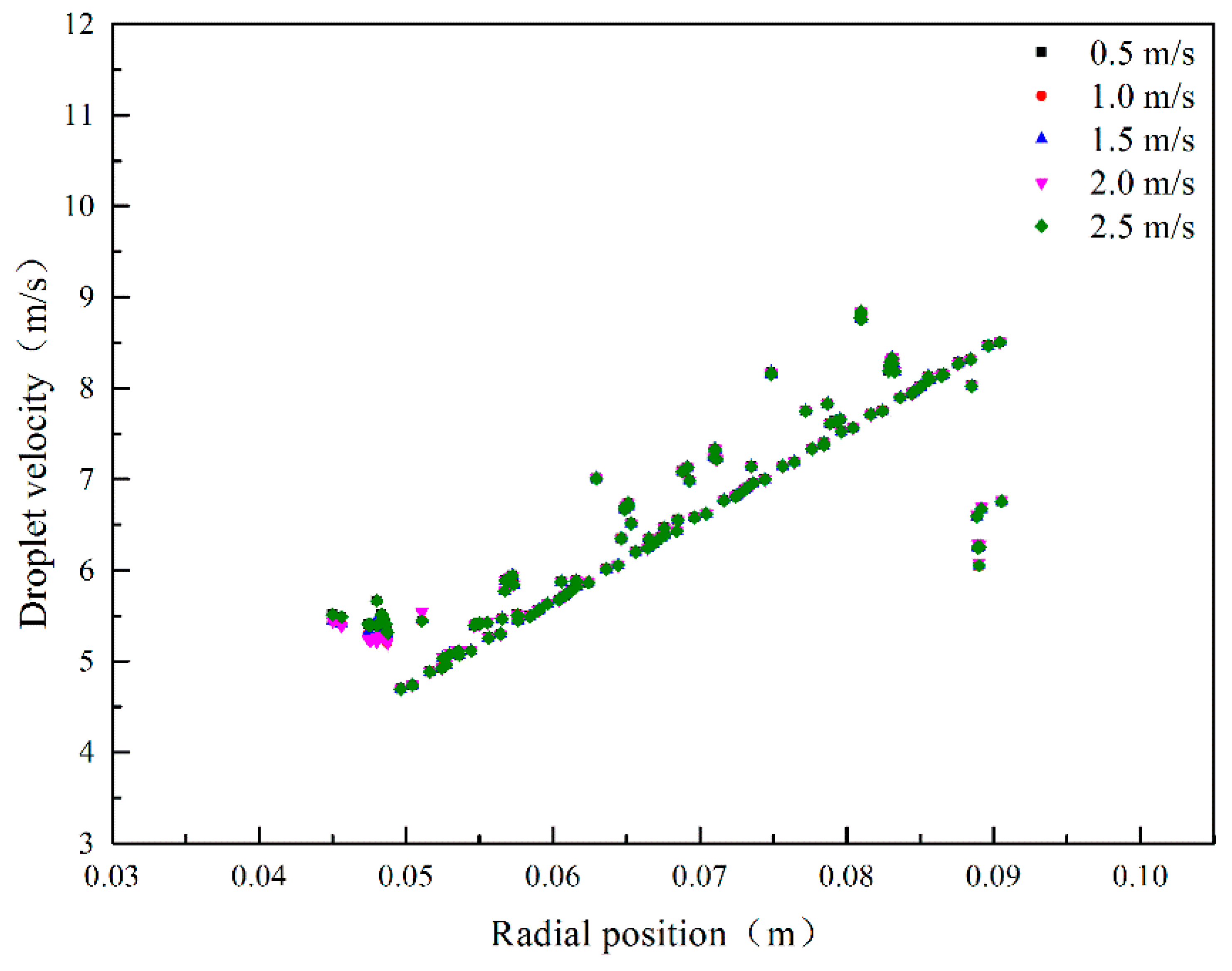
Figure 7 show the effect of initial droplet velocity on droplet velocity in the packing zone under the condition that initial droplet diameter is 3 mm and rotating speed is 900 rpm. In this zone, the droplet velocity is seldom influenced by initial droplet velocity. The reason is that the initial droplet velocity makes less contribution to resultant velocity compared with the tangential velocity generated by centrifugal force. On the other hand, the inelastic collision on droplets results in the loss of kinetic energy once droplets are sheared by packing.
3.1.2. Effect of Rotating Speed on Droplet Velocity
Figure 8 establishes the effect of rotating speed on droplet velocity in the packing zone under the condition that initial droplet diameter is 3 mm and initial droplet velocity is 0.5 m/s. In the packing zone, the rotating speed is dominant for droplet velocity increasing and it illustrates that the droplet velocity increases along with rotating speed increasing. As a consequence, Equation (33) for predicting droplet velocity in RPB is proposed by considering the influence of initial droplet velocity, rotating speed and radial position; validation Equation (34), predicted from Sang [14], is implemented. Finally, the mathematic expression declares that rotating speed and radial position have the main impacts on droplet velocity.
3.2. Average Residence Time Distribution in RPB
Analysis on selective absorption with MDEA indicated that it was kinetically selective towards H2S while thermodynamically selective towards CO2 [15]. According to the theory of the diffusion–reaction process for H2S selective absorption, the reaction and mass transfer on H2S are both instantaneously fast, while those process are restrained in CO2 mass transfer into the liquid film. Therefore, average residence time of droplet is considered as a key parameter in the H2S selective absorption into MDEA process in RPB. A method to obtain the residence time distribution is applied by tracking droplets, and residence time distributions in RPB under various initial droplet velocities and rotating speeds are shown in Figure 9.
Droplets interact intensely with the rotating packing and they are driven by centrifugal force, gravity, gas viscous resistance and packing frictional resistance, resulting in a frequent path change. Most of the droplets are accelerated to a synchronous motion with packing and are ejected in a radial spiral. With the increase of initial droplet velocity and rotating speed, the turbulence intensity increases with the increase of random trajectory. Table 3 summarizes the number of tracked droplets and average residence time in RPB under different rotating speeds and initial droplet velocities.
3.2.1. Effect of Initial Droplet Velocity on Average Residence Time
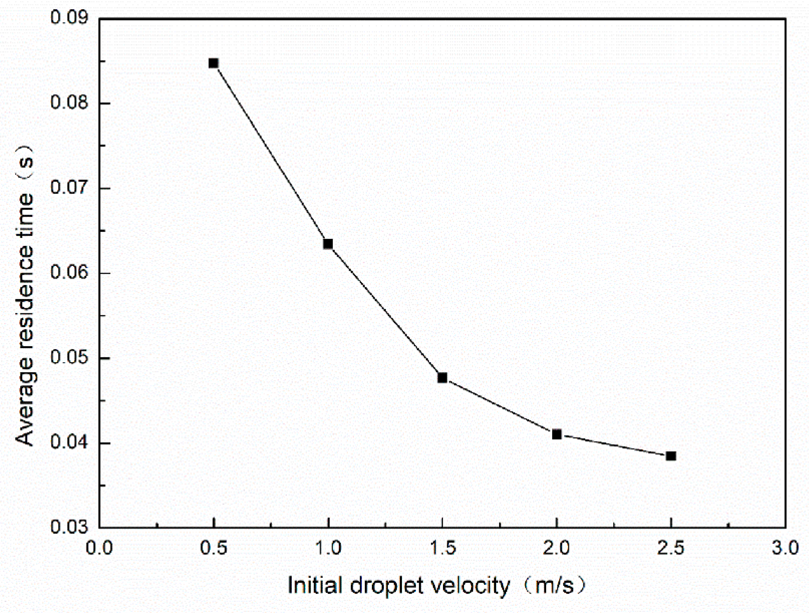
At the same rotating speed of 900 rpm, the average residence time changes drastically from a low initial velocity to a high initial velocity. Because of the increase of initial velocity, the time to pass through the whole packing will shorten correspondingly. As it is displayed in Figure 10, there is a turning point when the initial velocity reaches 1.5 m/s and the average residence time is reduced gradually.
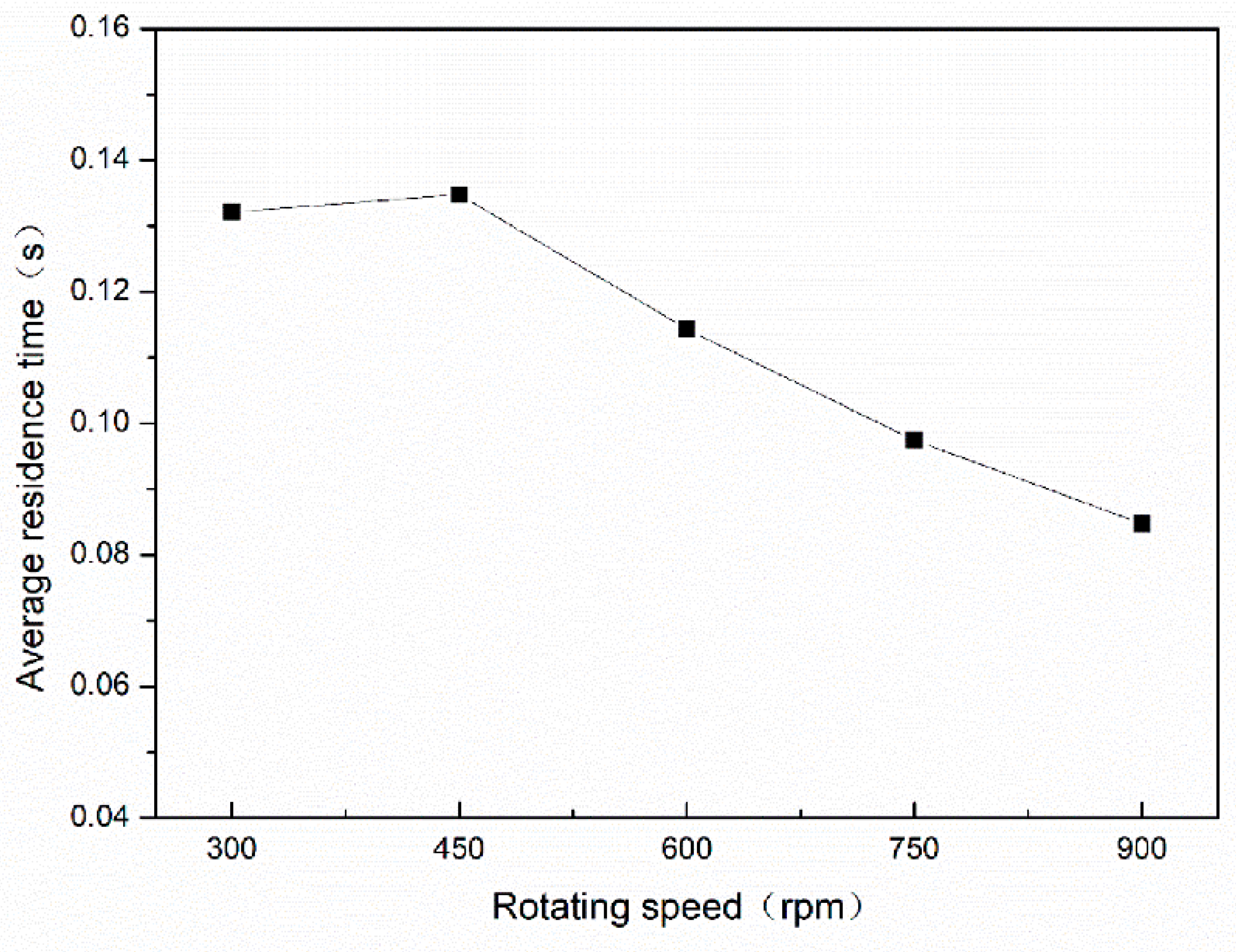
3.2.2. Effect of Rotating Speed on Average Residence Time
As shown in Figure 11, the droplet attains a tangential velocity when it enters the packing zone and a synchronous velocity will be achieved in a short time. For the sake of reducing residence time in RPB for H2S selective absorption, enhancing rotating speed seems to be an optimal way. Lower residence time in RPB compared with that in conventional column is ascribed to intensification process under centrifugal force. The higher the droplet velocity is, the lower the residence time obtained will be. Therefore, a commonsense calculation can be proposed to describe the residence time in RPB, and that is the ratio of radial distance to droplet velocity, calculated by Equation (35).
In the process of natural gas desulfurization and purification, H2S selective absorption and CO2 partial removal must meet the requirements on commercial natural gas, and the energy consumption also needs to be reduced in MDEA solution regeneration process. Therefore, higher mass transfer efficiency and lower residence time in RPB raise various concerns in natural gas purification. In the quantitative description of Qian’s work [16], it only took about 2.0 × 10⁻⁹ s for H2S to establish a steady concentration gradient while the process needed 1 s to complete for CO2. Thus, it can be highlighted from Figure 10, that the residence time can be only 0.039–0.085 s under a rotating speed of 900 rpm. Droplets go through the packing in a short residence time, especially with high initial droplet velocity and rotating speed.
3.3. Droplet Diameter Distribution in RPB
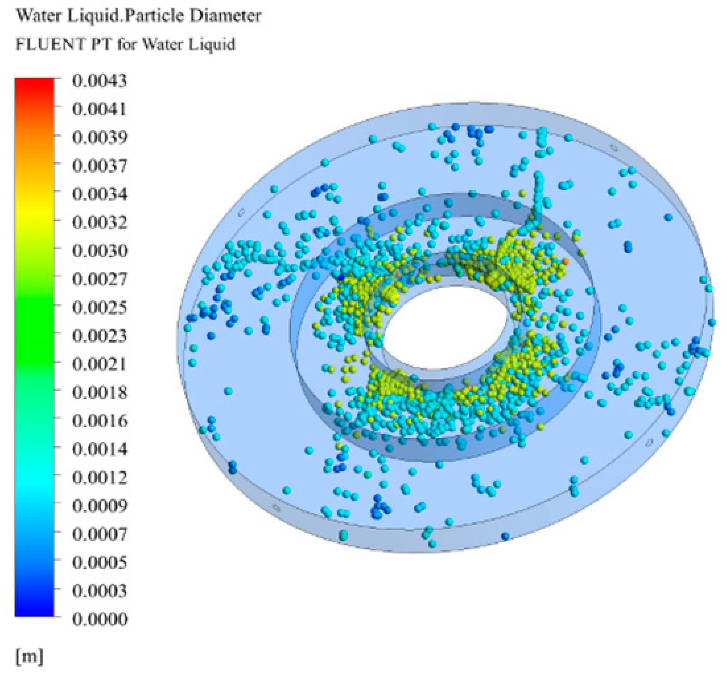
Droplet surface renewal frequency, which is defined as the percentage of surface updated per unit of time and effective mass transfer area, can be investigated by the droplet diameter distribution along radial position. Figure 12 shows the 3D droplet diameter distribution with an initial droplet velocity of 1.5 m/s, rotating speed of 600 rpm and initial droplet diameter of 3 mm. The droplet diameter changes a lot along the radial position, and collision and shear between droplet and packing result in sustaining breakup and coalescence. This also indicates that frequent surface renewal makes a prominent contribution to mass transfer.
3.3.1. Effect of Initial Droplet Diameter on Droplet Diameter Distribution
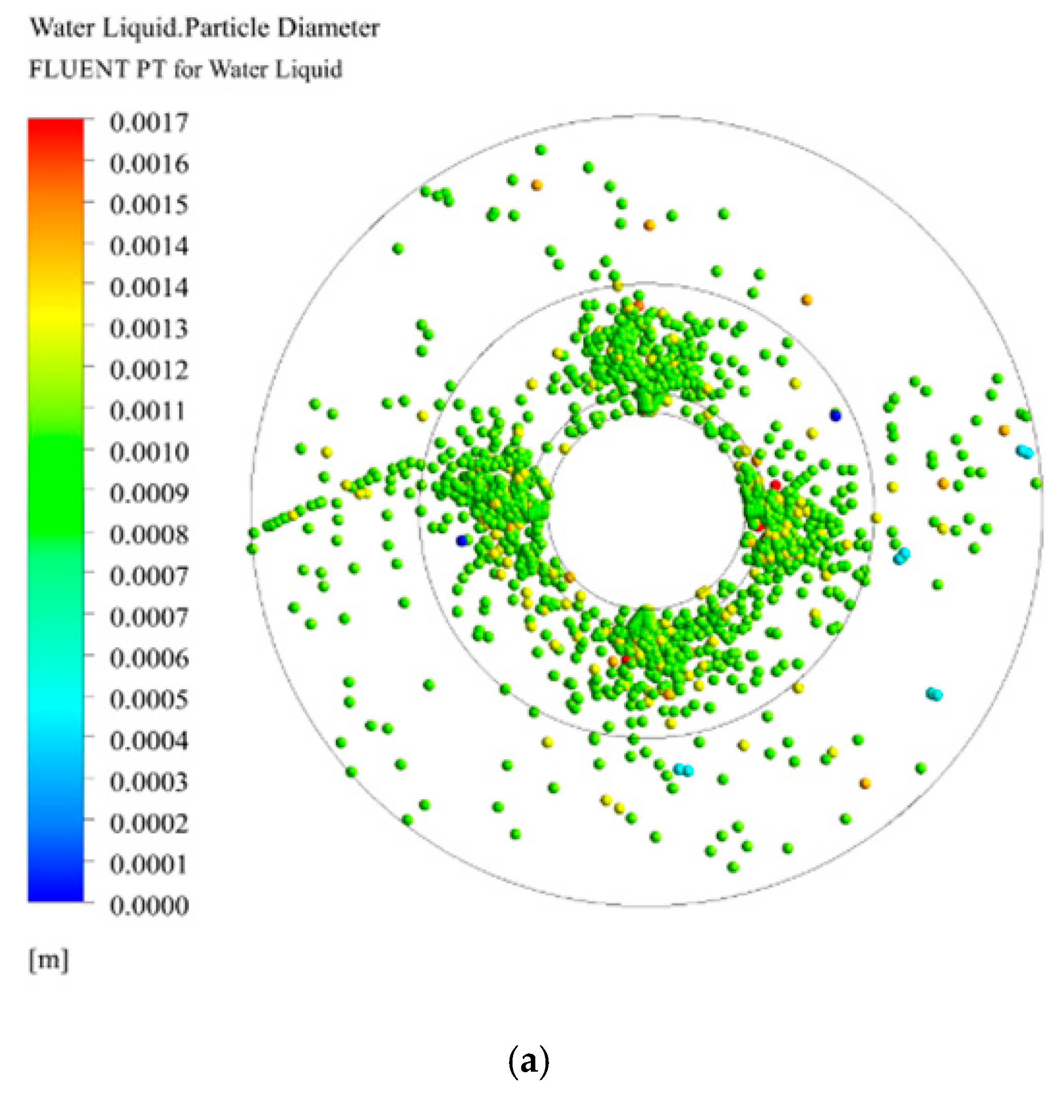
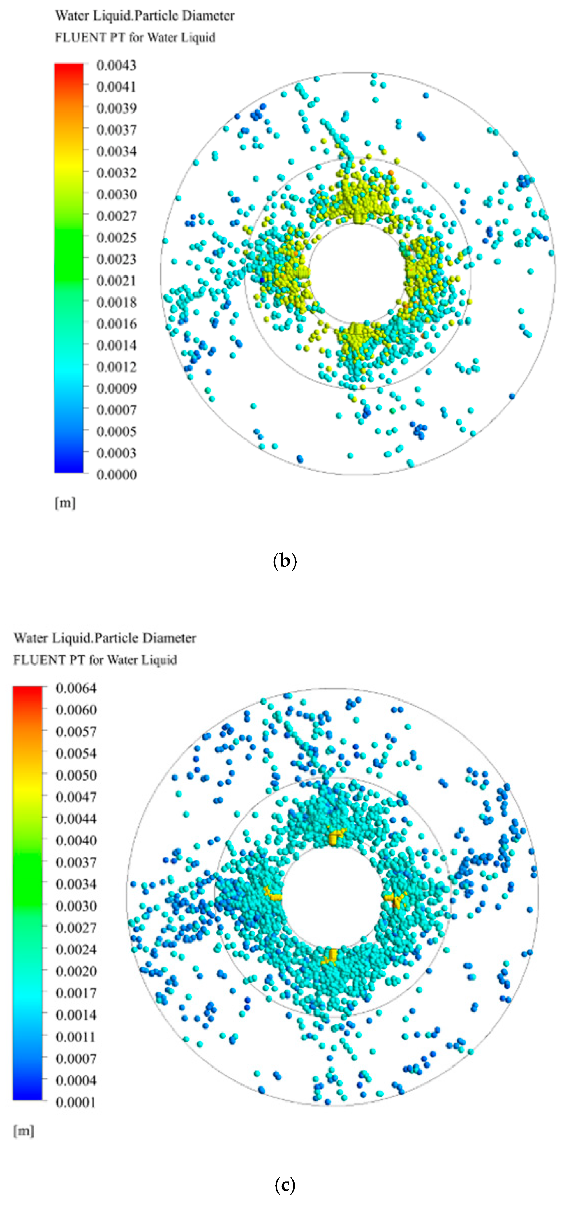
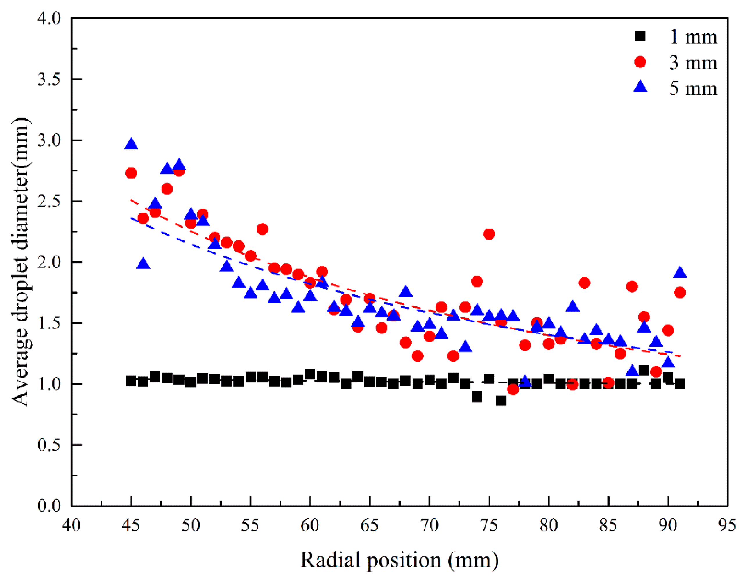
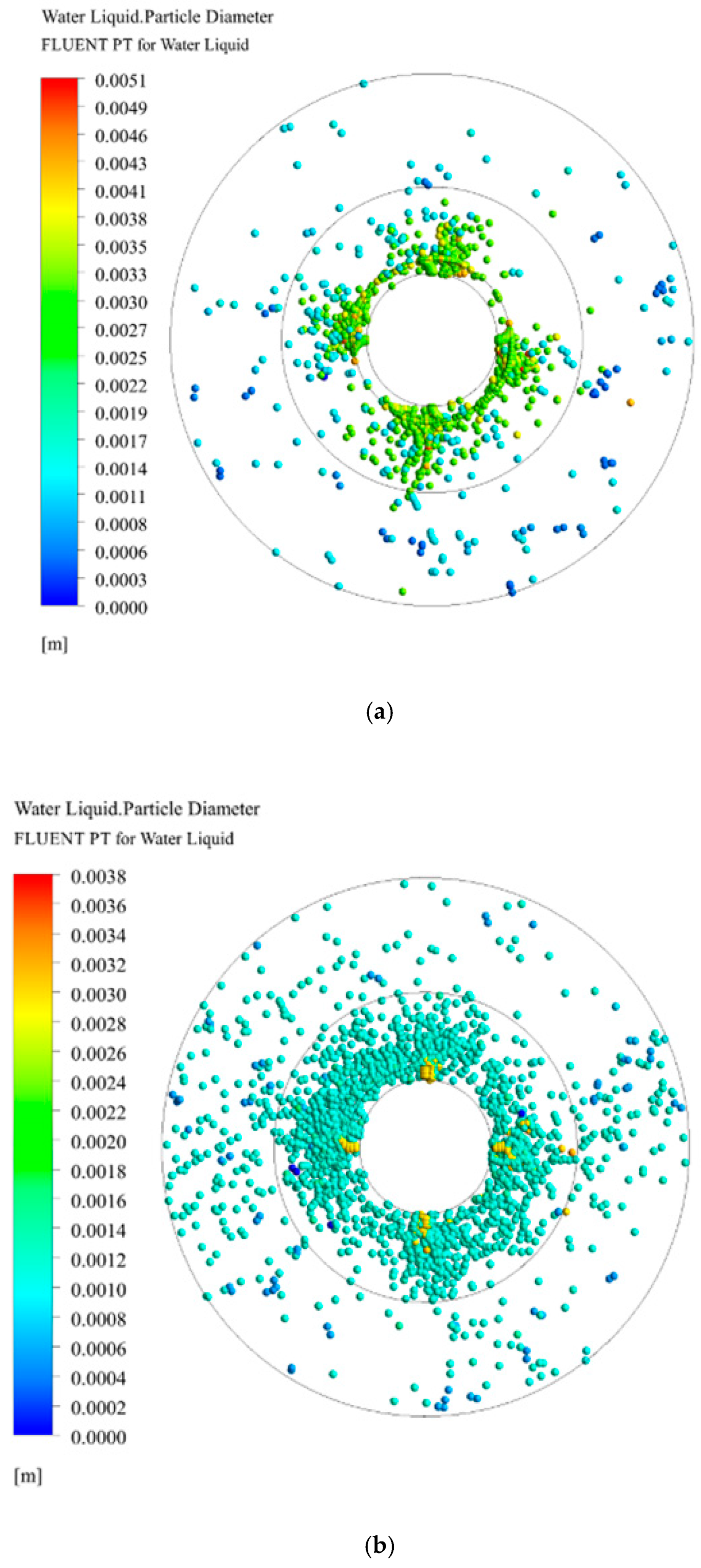
Figure 13 reveals that the droplet diameter increases with an increasing initial droplet diameter. After a larger droplet is introduced from the inlet, it tends to be broken up by packing because of lower surface tension needed to be overcome, and this results in a frequent surface renewal and an intensifying mass transfer process. Guo [17] obtained a formula by fitting relevant experimental data, , which indicated that the droplet diameter decreases along the radial direction. Both Figure 13 and Figure 14 show that the average droplet diameter is negatively correlated with the radius position, which is consistent with Guo’s research. Therefore, it also manifests that the CFD model introduced in this study reasonably predicts the droplet diameter distribution.
Specially, Figure 14 illuminates a particular phenomenon: There is rarely collision in the packing zone when the initial droplet diameter is 1 mm, compared with others. The reasons for the above phenomenon are as follows: (1) the packing size is larger than the initial droplet diameter; and (2) the inertial force under this condition is not enough to break the small droplet. Therefore, the study of the collision between 1-mm-diameter initial droplets and packing needs smaller packing size and larger inertial force. In a word, the effect of initial droplet diameter on droplet diameter distribution analyzed above can not only provide guidance for liquid distributor design, but also make a suitable proposal on choosing packing size.
3.3.2. Effect of Initial Droplet Velocity and Rotating Speed on Droplet Diameter
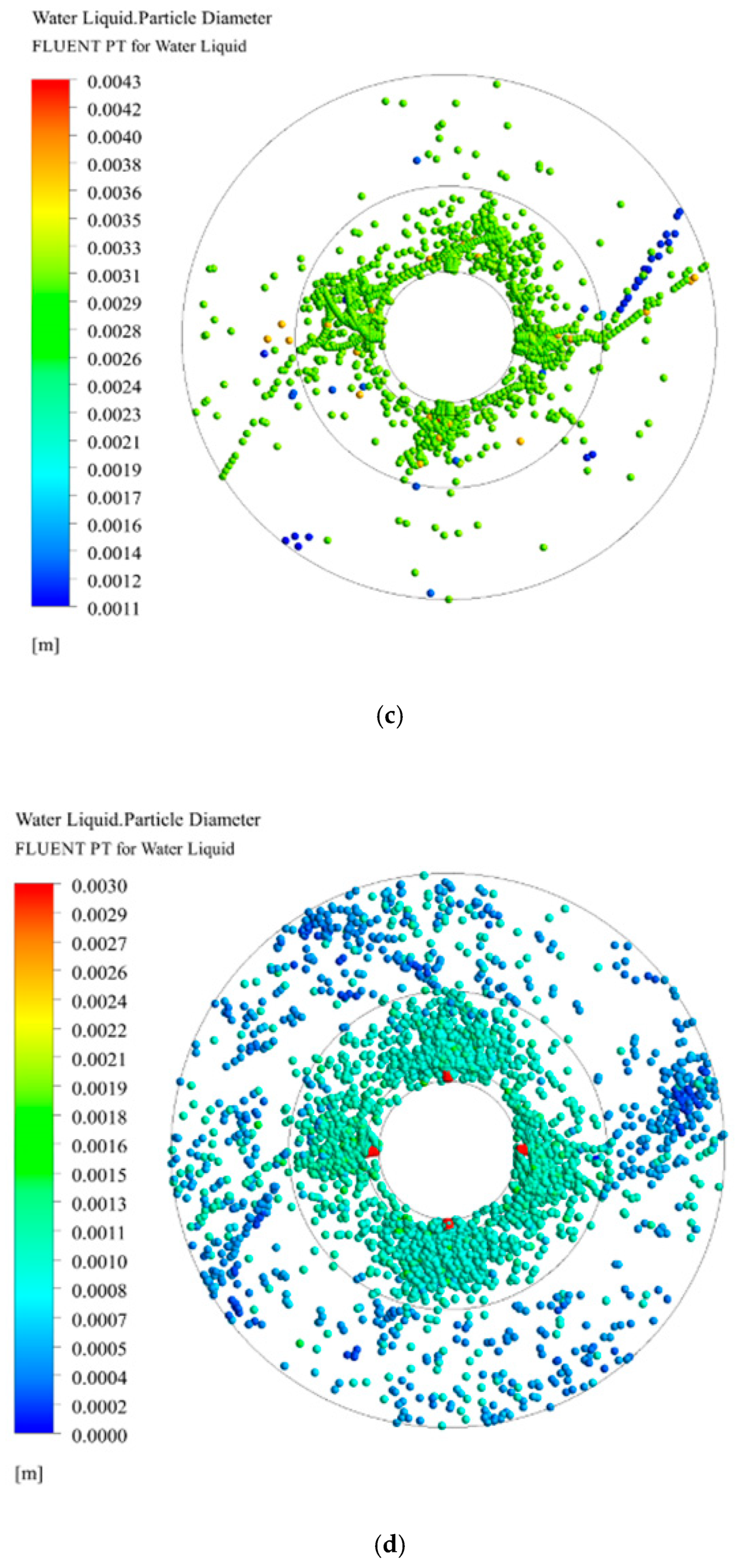
Figure 15 and Figure 16 illustrate that the average droplet diameter along the radial position decreases with the increase of initial droplet velocity from 0.5 to 2.5 m/s and with the increase of rotating speed from 300 rpm to 900 rpm. The droplet obtains the tangential velocity from the packing immediately, resulting in a violent collision and breakup among droplet and packing. Therefore, the droplet surface renewal frequency and effective mass transfer area have been enhanced remarkably.
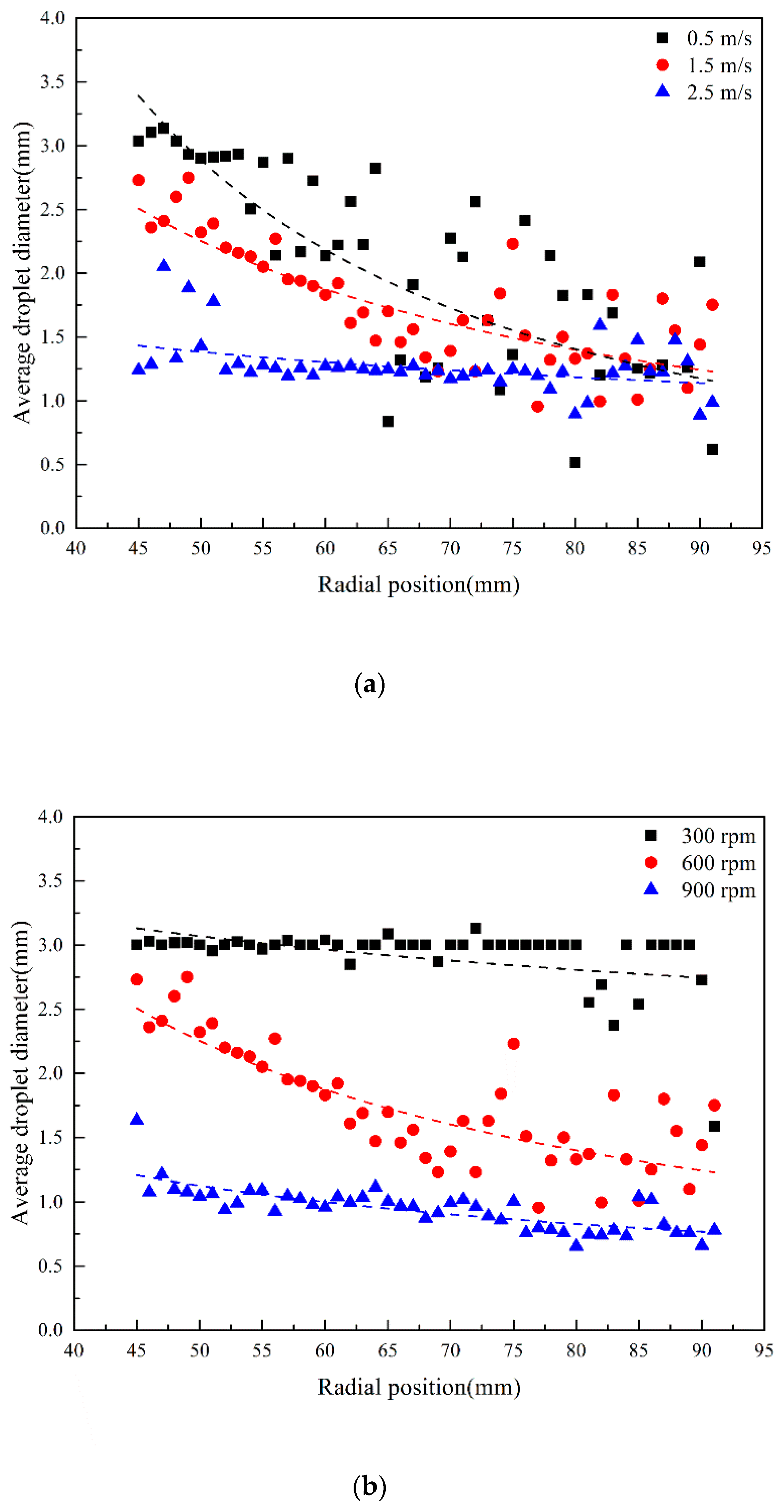
As shown in Figure 16a, under the same conditions of initial droplet diameter of 3 mm and rotating speed of 600 rpm, the average droplet diameter decreases drastically with the increase of initial droplet velocity from 0.5 to 2.5 m/s in the packing zone. In other words, the average droplet diameter with initial velocity of 2.5 m/s is less than the average droplet diameter with initial velocity of 1.5 m/s, which is less than the average droplet diameter with initial velocity of 0.5 m/s in same radial position. A higher initial droplet velocity means a greater initial kinetic energy, which is beneficial to the breakup of droplets when kinetic energy is greater than surface energy, so the phenomenon is obtained in Figure 16a. In addition, the initial droplet diameter of 3 mm will gradually break up into smaller droplets along the radial position and finally reaches a constant diameter of 1.25 mm at the outer packing zone. Thus, conclusions can be drawn that the minimum droplet diameter in RPB only depends on the rotating speed and that there exists a minimum rotating packing radial length for droplets to fully fragmentize.
From Figure 16b, it can be observed distinctly that average droplet diameter distribution changes regularly on initial droplet diameter and velocity of 3 mm and 1.5 m/s, respectively. The effect of rotating speed on droplet diameter indicates that the droplet diameter decreases with the increasing rotating speed. The centrifugal force is linear to radial position and is proportional to the second power of rotating speed. Therefore, a higher centrifugal force results in more drastic collisions and smaller droplet diameters. Further, a balance between shear force generated by rotating packing and surface tension on droplets is proposed and discussed under an appropriate rotating speed. When the rotating speed decreases to 300 rpm, the shear force cannot meet the surface tension, resulting in only a few droplet breakups at the end of packing. On the contrary (at 900 rpm), shear force is dominant instead of surface tension, so the droplet diameter changes gently.
Compared with the effect of initial droplet velocity on droplet diameter, a more obvious impact of rotating speed is obtained. Radial velocity and tangential velocity all contribute to droplet breakup, but the tangential velocity caused by rotating speed is dominant. Therefore, considering the effect of rotating speed, radial position and fluid density on droplet diameter, a fitting expression is obtained:
3.4. Principle of Processing Intensification in RPB
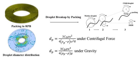
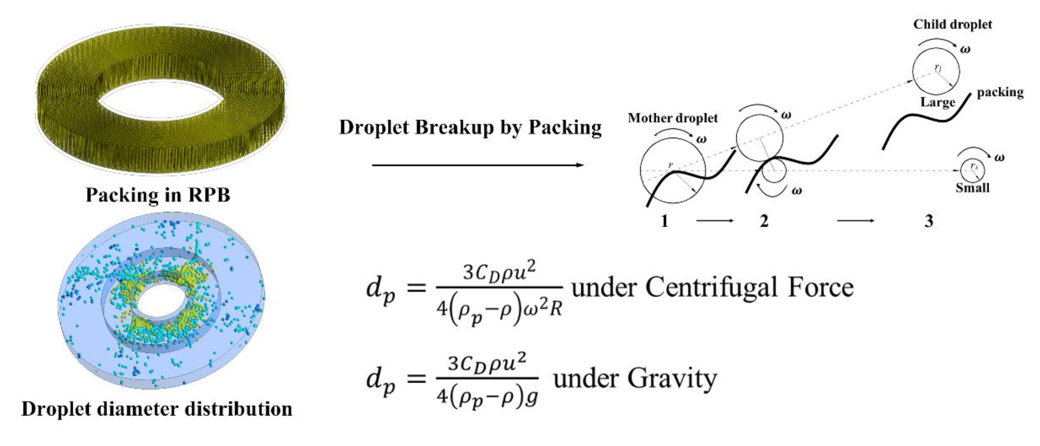
A comparison on particle diameter is conducted between RPB and conventional deposition process under gravity. Droplet force balance has been discussed in Equation (12) and the droplet diameter is calculated by two equations in Table 4, which were derived from Equations (12) and (13), considering mainly the centrifugal force in RPB (or gravity in deposition process) and drag force. Droplet diameter in different force fields is related to fluid density, droplet density, fluid velocity, droplet velocity and main acceleration. Generally speaking, the behavior in RPB can be considered as a processing intensification in force fields by replacing the term “” with “”. Thus, greater acceleration results in smaller droplet diameter and larger droplet surface area of mass transfer. According to the theory of mass transfer, the mass transfer rate is proportional to the surface area. Therefore, the mass transfer efficiency of RPB is 1–3 orders of magnitude greater than that in conventional equipment. In addition, some intensification in principle mentioned above will be implemented by coupling multiple fields like magnetic, electric and microwaves to explore their potential in RPB.
On the other hand, an arrangement should be taken as soon as possible by increasing the relative velocity between droplet and packing to enhance the collision of droplet-packing. Thus, an impinging stream distributor in an impinging stream rotating packed bed (IS-RPB) [18] has been put forward to increase the droplet initial velocity from the liquid distributor. A novel RPB called split packing RPB [19,20] (SP-RPB) can enhance the relative velocity in the packing zone by operating two separate rotating packings in opposing directions, which promotes a large surface area and makes a great contribution to surface renewal and mass transfer in the process of H2S selective absorption into MDEA solution.
4. Conclusions
A 3D CFD Eulerian–Lagrangian approach has been built by introducing a droplet breakup and coalescence model to investigate the droplet characteristics of RPB in H2S selective absorption into MDEA solution. Droplet characteristics such as droplet velocity, average residence time and average diameter in RPB have been analyzed by diagrams and correlations, which are compared with available experimental data in the literature [14,17]. The results show that the velocity increases with increasing rotating speed and radial position, but the opposite conclusion is made on the average residence time. Specially, in the end zone, a phenomenon called “end effect” in mass transfer intensification has been observed and can be illuminated by droplet back-mixing. A correlation on droplet velocity has been deduced in Equation (33) mainly associated with rotating speed and radial position rather than initial droplet velocity. Under the condition of 900 rpm, a short average residence time 0.039–0.085 s in RPB has been recommended for H2S selective absorption into MDEA solution. This is because the reaction and mass transfer rate of H2S are both instantaneously fast compared with CO2, thus a short average residence time allows for efficient selective absorption between H2S and CO2. When the initial droplet velocity and rotating speed increase, the average droplet diameter decreases inordinately. However, the initial droplet diameter has a restriction (1 mm) to be captured and broken by the packing size under the simulation conditions. Furthermore, conclusions are made that the rotating speed determines the minimum droplet diameter and that a packing length in the radial direction is needed to meet droplet breakup completely. In addition, a balance between shear force and surface tension on the droplet indicates an appropriate rotating speed. A correlation (Equation (36)) on droplet diameter is obtained considering the effect of rotating speed, radial position and fluid density.
The simulation results indicate this CFD approach has the capability in describing droplet characteristics, and an investigation on principle in RPB has been conducted based on these results. Processing in RPB can be regarded as an intensification of a traditional separation device in gravity by replacing the term “” with “” and some coupled field with centrifugal force like magnetic, electric and microwaves, which will inspire further potential in RPB. Finally, IS-RPB and SP-RPB as novel equipment have made a great contribution to surface renewal and mass transfer in the process of H2S selective absorption into MDEA solution through increasing the relative velocity and collision between droplets and packing.
Author Contributions
All authors contributed to the manuscript. Z.W. proposed the main idea; X.W. performed the CFD simulation; T.Y. wrote the manuscript; S.W. improved the manuscript; Z.L. provided many key suggestions; X.D. collected and analyzed data.
Funding
This research received no external funding.
Conflicts of Interest
The authors declare no conflict of interest.
Nomenclatures
| CFD | Computational fluid dynamics |
| HTU | Height of mass transfer unit |
| IS-RPB | Impinging stream RPB |
| RPB | Rotating packed bed |
| RSR | Rotor-stator reactor |
| SP-RPB | Split packing RPB |
| TAB | Taylor analogy breakup |
| Latin symbols | |
| Drag coefficient | |
| Aerodynamic force of droplet (N) | |
| External body force (N) | |
| Drag force (N) | |
| Force in rotating reference frame in x direction (N) | |
| Force in rotating reference frame in y direction (N) | |
| Virtual mass force (N) | |
| Additional acceleration term | |
| Influence of the buoyancy force | |
| Influence of the mean velocity gradients | |
| Turbulent Prandtl number for energy | |
| R | Radial position (m) |
| Actual collision parameter | |
| Critical offset of collision | |
| Initial droplet diameter (mm) | |
| Arithmetic mean diameter of two droplet (m) | |
| Gravitational vector (9.8 m/s2) | |
| Turbulence kinetic energy | |
| Mass of droplet (kg) | |
| Mass of large droplet (kg) | |
| Mass of small droplet (kg) | |
| Static pressure (Pa) | |
| Radius of large droplet (m) | |
| Radius of small droplet (m) | |
| Fluid velocity (m/s) | |
| Initial droplet velocity (m/s) | |
| Velocity of large droplet (m/s) | |
| Droplet velocity (m/s) | |
| Whirl velocity (m/s) | |
| Velocity of small droplet (m/s) | |
| Relative velocity (m/s) | |
| Displacement of droplet (m) | |
| Greek symbols | |
| Fluid density (kg/m3) | |
| Gas density (kg/m3) | |
| Liquid density (kg/m3) | |
| Droplet density (kg/m3) | |
| Rotating speed (rpm) | |
| Centrifugal acceleration (rad/s) | |
| Gas viscosity (mPa·s) | |
| Liquid viscosity (mPa·s) | |
| Molecular viscosity (mPa·s) | |
| Turbulent viscosity (mPa·s) | |
| Liquid surface tension (N/m) | |
| Dissipation rate | |
| Dimensionless groups | |
| Reynolds number | |
| Weber number | |
References
- Chen, Y.-S.; Lin, F.-Y.; Lin, C.-C.; Tai, C.Y.-D.; Liu, H.-S. Packing Characteristics for Mass Transfer in a Rotating Packed Bed. Ind. Eng. Chem. Res. 2006, 45, 6846–6853. [Google Scholar] [CrossRef]
- Neumann, K.; Gladyszewski, K.; Gross, K.; Qammar, H.; Wenzel, D.; Gorak, A.; Skiborowski, M. A guide on the industrial application of rotating packed beds. Chem. Eng. Res. Des. 2018, 134, 443–462. [Google Scholar] [CrossRef]
- Burns, J.R.; Ramshaw, C. Process intensification: Visual study of liquid maldistribution in rotating packed beds. Chem. Eng. Sci. 1996, 51, 1347–1352. [Google Scholar] [CrossRef]
- Guo, K.; Guo, F.; Feng, Y.; Chen, J.; Zheng, C.; Gardner, N.C. Synchronous visual and RTD study on liquid flow in rotating packed-bed contactor. Chem. Eng. Sci. 2000, 55, 1699–1706. [Google Scholar] [CrossRef]
- Li, Y.; Wang, S.; Sun, B.; Arowo, M.; Zou, H.; Chen, J.; Shao, L. Visual study of liquid flow in a rotor-stator reactor. Chem. Eng. Sci. 2015, 134, 521–530. [Google Scholar] [CrossRef]
- Sang, L.; Luo, Y.; Chu, G.-W.; Zhang, J.-P.; Xiang, Y.; Chen, J.-F. Liquid flow pattern transition, droplet diameter and size distribution in the cavity zone of a rotating packed bed: A visual study. Chem. Eng. Sci. 2017, 158, 429–438. [Google Scholar] [CrossRef]
- Shi, X.; Xiang, Y.; Wen, L.-X.; Chen, J.-F. CFD analysis of liquid phase flow in a rotating packed bed reactor. Chem. Eng. J. 2013, 228, 1040–1049. [Google Scholar] [CrossRef]
- Ouyang, Y.; Zou, H.-K.; Gao, X.-Y.; Chu, G.-W.; Xiang, Y.; Chen, J.-F. Computational fluid dynamics modeling of viscous liquid flow characteristics and end effect in rotating packed bed. Chem. Eng. Process. Process Intensif. 2018, 123, 185–194. [Google Scholar] [CrossRef]
- Ouyang, Y.; Wang, S.; Xiang, Y.; Zhao, Z.; Wang, J.; Shao, L. CFD analyses of liquid flow characteristics in a rotor-stator reactor. Chem. Eng. Res. Des. 2018, 134, 186–197. [Google Scholar] [CrossRef]
- Xie, P.; Lu, X.; Yang, X.; Ingham, D.; Ma, L.; Pourkashanian, M. Characteristics of liquid flow in a rotating packed bed for CO2 capture: A CFD analysis. Chem. Eng. Sci. 2017, 172, 216–229. [Google Scholar] [CrossRef]
- Ko, G.H.; Ryou, H.S. Modeling of droplet collision-induced breakup process. Int. J. Multiph. Flow 2005, 31, 723–738. [Google Scholar] [CrossRef]
- Wang, Z.; Yang, T.; Liu, Z.; Wang, S.; Gao, Y.; Wu, M. Mass Transfer in a Rotating Packed Bed: A Critical Review. Chem. Eng. Process. Process Intensif. 2019, 139, 78–94. [Google Scholar] [CrossRef]
- Liu, Y.; Luo, Y.; Chu, G.-W.; Luo, J.-Z.; Arowo, M.; Chen, J.-F. 3D numerical simulation of a rotating packed bed with structured stainless steel wire mesh packing. Chem. Eng. Sci. 2017, 170, 365–377. [Google Scholar] [CrossRef]
- Sang, L.; Luo, Y.; Chu, G.W.; Liu, Y.Z.; Liu, X.Z.; Chen, J.F. Modeling and experimental studies of mass transfer in the cavity zone of a rotating packed bed. Chem. Eng. Sci. 2017, 170, 355–364. [Google Scholar] [CrossRef]
- Qian, Z.; Li, Z.-H.; Guo, K. Industrial Applied and Modeling Research on Selective H2S Removal Using a Rotating Packed Bed. Ind. Eng. Chem. Res. 2012, 51, 8108–8116. [Google Scholar] [CrossRef]
- Qian, Z.; Xu, L.-B.; Li, Z.-H.; Li, H.; Guo, K. Selective Absorption of H2S from a Gas Mixture with CO2 by Aqueous N-Methyldiethanolamine in a Rotating Packed Bed. Ind. Eng. Chem. Res. 2010, 49, 6196–6203. [Google Scholar] [CrossRef]
- Guo, F.; Zheng, C.; Guo, K.; Feng, Y.; Gardner, N.C. Hydrodynamics and mass transfer in cross-flow rotating packed bed. Chem. Eng. Sci. 1997, 52, 3853–3859. [Google Scholar] [CrossRef]
- Yang, P.-F.; Luo, S.; Zhang, D.-S.; Yang, P.-Z.; Liu, Y.-Z.; Jiao, W.-Z. Extraction of nitrobenzene from aqueous solution in impinging stream rotating packed bed. Chem. Eng. Process. Process Intensif. 2018, 124, 255–260. [Google Scholar] [CrossRef]
- Rajan, S.; Kumar, M.; Ansari, M.J.; Rao, D.P.; Kaistha, N. Limiting Gas Liquid Flows and Mass Transfer in a Novel Rotating Packed Bed (HiGee). Ind. Eng. Chem. Res. 2011, 50, 986–997. [Google Scholar] [CrossRef]
- Shivhare, M.K.; Rao, D.P.; Kaistha, N. Mass transfer studies on split-packing and single-block packing rotating packed beds. Chem. Eng. Process. Process Intensif. 2013, 71, 115–124. [Google Scholar] [CrossRef]
Figure 1.
Schematic diagram of rotating packed bed (RPB) (counter-currently).

Figure 2.
Three types of liquid pattern in RPB with a video camera, reproduced with permission from [3]. Copyright Elsevier, 1996.
Figure 2.
Three types of liquid pattern in RPB with a video camera, reproduced with permission from [3]. Copyright Elsevier, 1996.

Figure 3.
(a) 3D physical model diagram (1, gas inlet; 2, liquid inlet; 3, gas outlet; 4, foursquare obstacles; 5, liquid outlet; 6, end zone; 7, packing zone; 8, cavity zone). (b) Grid refinement.
Figure 3.
(a) 3D physical model diagram (1, gas inlet; 2, liquid inlet; 3, gas outlet; 4, foursquare obstacles; 5, liquid outlet; 6, end zone; 7, packing zone; 8, cavity zone). (b) Grid refinement.

Figure 4.
Schematic diagram of the coalescence process.

Figure 5.
The grid independence checking.

Figure 6.
The velocity values and vectors under various initial droplet velocities and rotating speeds. (a) = 0.5 m/s, = 300 rpm; (b) = 0.5 m/s, = 600 rpm; (c) = 0.5 m/s, = 900 rpm; (d) = 1.5 m/s, = 600 rpm; (e) = 2.5 m/s, = 600 rpm.
Figure 6.
The velocity values and vectors under various initial droplet velocities and rotating speeds. (a) = 0.5 m/s, = 300 rpm; (b) = 0.5 m/s, = 600 rpm; (c) = 0.5 m/s, = 900 rpm; (d) = 1.5 m/s, = 600 rpm; (e) = 2.5 m/s, = 600 rpm.


Figure 7.
The effect of initial droplet velocity on droplet velocity in the packing zone.

Figure 8.
The effect of rotating speed on droplet velocity in the packing zone.

Figure 9.
Residence time distribution in RPB under various initial droplet velocities and rotating speeds. (a) = 0.5 m/s, = 300 rpm; (b) = 0.5 m/s, = 600 rpm; (c) = 0.5 m/s, = 900 rpm; (d) = 1.5 m/s, = 600 rpm; (e) = 2.5 m/s, = 600 rpm.
Figure 9.
Residence time distribution in RPB under various initial droplet velocities and rotating speeds. (a) = 0.5 m/s, = 300 rpm; (b) = 0.5 m/s, = 600 rpm; (c) = 0.5 m/s, = 900 rpm; (d) = 1.5 m/s, = 600 rpm; (e) = 2.5 m/s, = 600 rpm.


Figure 10.
Effect of initial droplet velocity on average residence time.

Figure 11.
Effect of rotating speed on average residence time.

Figure 12.
A 3D droplet diameter distribution in RPB.

Figure 13.
The droplet diameter distribution under different initial droplet diameters. (a) = 1 mm; (b) = 3 mm; (c) = 5 mm.
Figure 13.
The droplet diameter distribution under different initial droplet diameters. (a) = 1 mm; (b) = 3 mm; (c) = 5 mm.


Figure 14.
Effect of initial droplet diameter on average droplet diameter.

Figure 15.
Droplet diameter under various initial droplet velocities and rotating speeds. (a) = 0.5 m/s, = 600 rpm; (b) = 2.5 m/s, = 600 rpm; (c) = 1.5 m/s, = 300 rpm; (d) = 1.5 m/s, = 900 rpm.
Figure 15.
Droplet diameter under various initial droplet velocities and rotating speeds. (a) = 0.5 m/s, = 600 rpm; (b) = 2.5 m/s, = 600 rpm; (c) = 1.5 m/s, = 300 rpm; (d) = 1.5 m/s, = 900 rpm.


Figure 16.
Effect of initial droplet velocity and rotating speed on average droplet diameter. (a) = 3 mm, = 600 rpm; (b) = 3 mm, = 1.5 m/s.
Figure 16.
Effect of initial droplet velocity and rotating speed on average droplet diameter. (a) = 3 mm, = 600 rpm; (b) = 3 mm, = 1.5 m/s.


Table 1.
The main geometric dimensions of RPB.
| Inner Diameter (mm) | Outer Diameter (mm) | Height (mm) | |
|---|---|---|---|
| RPB | 45 | 160 | 24 |
| Packing | 48 | 92 | 20 |
Table 2.
Fluid properties.
| CH4 | C2H6 | C3H8 | C4H10 | C5H12 | CO2 | H2S | N2 | |
|---|---|---|---|---|---|---|---|---|
| Gas (mol %) | 85.71 | 2.30 | 0.73 | 0.47 | 0.24 | 4.25 | 5.04 | 1.27 |
| Liquid (m %) | An MDEA aqueous solution with a mass fraction of 35% | |||||||
Table 3.
Average residence time under various initial droplet velocities and rotating speeds.
| Rotating Speed (rpm) | 300 | 600 | 900 | 900 | 900 |
|---|---|---|---|---|---|
| Initial droplet velocity (m/s) | 0.5 | 0.5 | 0.5 | 1.5 | 2.5 |
| Number of droplets | 58 | 111 | 183 | 360 | 391 |
| Total residence time (s) | 7.7 | 12.7 | 15.5 | 17.2 | 15.0 |
| Average residence time (s) | 0.132 | 0.114 | 0.085 | 0.048 | 0.039 |
Table 4.
Droplet diameter under different force fields.
| Force Field | Droplet Diameter |
|---|---|
| Rotating packed bed | |
| deposition process under gravity |
© 2019 by the authors. Licensee MDPI, Basel, Switzerland. This article is an open access article distributed under the terms and conditions of the Creative Commons Attribution (CC BY) license (http://creativecommons.org/licenses/by/4.0/).
Share and Cite
MDPI and ACS Style
Wang, Z.; Wu, X.; Yang, T.; Wang, S.; Liu, Z.; Dan, X. Droplet Characteristics of Rotating Packed Bed in H2S Absorption: A Computational Fluid Dynamics Analysis. Processes 2019, 7, 724. https://0-doi-org.brum.beds.ac.uk/10.3390/pr7100724
AMA Style
Wang Z, Wu X, Yang T, Wang S, Liu Z, Dan X. Droplet Characteristics of Rotating Packed Bed in H2S Absorption: A Computational Fluid Dynamics Analysis. Processes. 2019; 7(10):724. https://0-doi-org.brum.beds.ac.uk/10.3390/pr7100724
Chicago/Turabian StyleWang, Zhihong, Xuxiang Wu, Tao Yang, Shicheng Wang, Zhixi Liu, and Xiaodong Dan. 2019. "Droplet Characteristics of Rotating Packed Bed in H2S Absorption: A Computational Fluid Dynamics Analysis" Processes 7, no. 10: 724. https://0-doi-org.brum.beds.ac.uk/10.3390/pr7100724
Note that from the first issue of 2016, this journal uses article numbers instead of page numbers. See further details here.