Article

Comparison of Temperature Control and Temperature Difference Control for a Kaibel Dividing Wall Column

College of Information Science and Technology, Beijing University of Chemical Technology, Beijing 100029, China
*
Author to whom correspondence should be addressed.
Submission received: 13 September 2019 / Revised: 5 October 2019 / Accepted: 18 October 2019 / Published: 21 October 2019
(This article belongs to the Special Issue Process Optimization and Control)

Abstract

:
A dividing wall column (DWC) effectively intensifies the distillation process with a reduced energy consumption, capital investment, and space. The three-product DWC has been investigated intensively and extensively; however, the four-product Kaibel DWC has received scarce attention. This study aimed to propose feasible control structures for the Kaibel DWC using only temperature sensors in order to promote its industrialization. Two temperature control structures, two temperature difference control structures, and two double temperature difference control structures were studied. The feasibility of the six proposed control structures was verified with a wide variety of feed disturbances. In most cases, temperature difference control was better than temperature control to maintain product purities. The dynamic performances proved that the inserted feed disturbances were handled well. These results help to promote the industrialization of the Kaibel DWC.

1. Introduction

In chemical industries, distillation unit operation is one of the most widely applied technology for separating liquid mixtures, but it has a high energy consumption and low energy efficiency. A dividing wall column (DWC) is a promising strategy that can considerably save on capital and operating costs. The three-product Petlyuk DWC, which has been successfully employed in chemical industries, provides a feasible method for process intensification techniques [1]. DWC contains only one distillation column integrated with a vertical dividing wall that requires a substantially decreased space, capital cost, and operating expense as compared with the traditional processes [2,3]. The three-product Petlyuk DWC is able to reduce energy usage by about 30% [4], while the four-product Kaibel DWC can save about 40% on energy usage [5,6]. Kaibel [7] first proposed the distillation column with a vertical partition that is able to separate four pure fractions, and researchers [8] introduced this arrangement as the four-product Kaibel DWC, as shown in Figure 1. A, B, C, and D represent the four pure fractions. F stands for the feed while S1 and S2 indicate the upper and lower side products.
The complicated structure of a DWC, however, inevitably produces excessive interactions and highly nonlinear behaviors. These intensify the difficulty of the design and control of a DWC. Misgivings about the optimization and controllability problems impedes the industrialization of a DWC. In order to provide a way toward the industrialization of a DWC, pioneer researchers and scholars have studied the design and control of different DWC configurations, including the three-product Petlyuk DWC, azeotropic DWC (ADWC), extractive DWC (EDWC), and reactive DWC (RDWC).
Based on the three-product Petlyuk DWC, Wolff and Skogestad [9] proposed a three-point control scheme using the reflux stream controlling the top product purity, the vapor boilup controlling the bottom product purity, and the side product stream controlling its purity. Wang and Wong [10] investigated the trade-off between the energy saving ability of the three-product Petlyuk DWC and its controllability. Ling and Luyben [11] studied a four-point control structure with an additional pairing of βL-y2 besides the three-point control structure (y2 is the heavy impurity o-xylene in the overhead vapor stream at the top of the prefractionator) on the basis of the three-product Petlyuk DWC. They [12] further investigated a four-point temperature control (TC) structure and the corresponding temperature difference control (TDC) structure for the same system. Dwivedi et al. [13,14] studied feasible composition and composition/temperature cascade control schemes for both the three-product Petlyuk DWC and the four-product extended Petlyuk DWC. Fan et al. [15] and Qian et al. [16] investigated the controllability and operability of the Kaibel DWC. Various feasible control schemes were proposed, including a composition control scheme, a TC scheme, and a composition/temperature cascade control scheme. Jia et al. [17] investigated a new optimization strategy with a support vector machine strategy, as well as a particle swarm optimization method for the synthesis and design of the three-product DWC. They [18] also compared the TC and composition/temperature cascade control structures on the basis of the same system, and the results show that a pure temperature control structure is the best. Kiss and Ignat [19] and Kiss and Suszwalak [20] combined azeotropic/extractive distillation with DWC (ADWC/EDWC) for the first time and proved that ADWC/EDWC was able to save energy usage by about 20% using different systems. Le et al. [21] investigated a heterogeneous ADWC configuration that could save energy usage by about 20% compared with the original configuration when separating water and acetic acid. Luyben [22] modified the bioethanol dehydration EDWC with vapor recompression. Through a portion of vapor recompression and the introduction of auxiliary condensers, the dynamic robustness of the configuration improved a lot. Staak and Grutzner [23] aimed to close the gap between the published data for the EDWC and the industrialized EDWC. An EDWC developed and implemented by the Lonza was carried out based on simulations without pilot or mini plant experiments. This method significantly shortened the time-to-market cycle and helped save on the industrialization investment to a large extent. Delgado-Delgado et al. [24] experimentally tested the production of ethyl acetate in a RDWC and the experimentally observed results agreed with the results of simulations. Feng et al. [25] studied the energy-saving potential of a combination of a vapor recompression heat pump (VRHP) with a lower partitioned RDWC. Through integrating a preheater, the innovative VRHP-assisted RDWC configuration could reduce the energy cost by 49.86%. Kiss and Suszwalak [26] used state-of-the-art sequential quadratic programming for the synthesis and design of a RDWC. The obtained results showed that the energy-saving ability of this RDWC is as high as 58% compared with the typical reaction and distillation process.
The main features of the Kaibel DWC are the vertical dividing wall, the liquid split above the dividing wall, and the vapor split below the dividing wall. For simulation purposes, the thermally equivalent configuration of the Kaibel DWC with the thermally coupled liquid and vapor streams between the columns are shown in Figure 2. This paper proposes two temperature control (TC1 and TC2) structures, two temperature difference control (TDC1 and TDC2) structures, and two double temperature difference control (DTDC1 and DTDC2) structures for the Kaibel DWC. Sensitivity analysis (SA) and singular value decomposition analysis (SVDA) were used for choosing reference temperatures and sensitive temperatures. As one TC loop is generally required for each split in order to stabilize the distillation operation [27], we should use at least four temperature controllers in the Kaibel DWC. TC1, TDC1, and DTDC1 employ liquid splitting in the control structures, while TC2, TDC2, and DTDC2 use vapor splitting in the control structures. The feasibility of the six proposed control structures was examined through a wide range of feed disturbances. Comparisons and discussions are made based on the dynamic performances.

2. Steady-State Design

A mixture of n-pentane (A), n-hexane (B), n-heptane (C), and n-octane (D), as shown in Figure 2, was employed in the case study for the four-product Kaibel DWC. F, D, S1, S2, B, RR, QR, RL and RV represent the feed, distillate product, upper side product, lower side product, bottom product, reflux ratio, reboiler duty, liquid split ratio and vapor split ratio, respectively. The simulation software was Aspen Plus V8.0 (Bedford, Massachusetts, USA). Redlich-Kwong-Soave (RKS) was used as the property method. As shown in Figure 2, a sharp AB/CD split was carried out in the prefractionator and three sharp splits including A/B, B/C, and C/D splits were performed in the upper, middle, and lower part of the main column.
The molar composition specifications for the top and the bottom product were 0.99, while those for the side products were 0.98. To maintain all the four product specifications, four variables were varied, which were the top distillate flow rate (D), the upper side product flow rate (S1), the lower side product flow rate (S2), and the liquid reflux rate (L). With the reboiler duty (QR) being the objective function, the liquid and vapor split ratios (RL and RV) were optimized. The optimal steady-state design is presented in Figure 2 and elaborated in detail in our previous study [13].

3. Control Structures

Two TC structures, two TDC structures, and two DTDC structures were studied for this paper. Proportional-integral (PI) controllers were used in the case study. In order to be more applicable in industries, only temperature controllers (no composition controllers) were used. The heat duty of the condenser controlled the top column pressure of the Kaibel DWC and the product flow rates controlled the levels. For those pressure and level controls, they were not shown in the control scheme figures and their tuning parameters used the suggested values from the literature [28,29].
There are six available manipulated variables (u) besides the manipulated variables used for pressure control and level control:
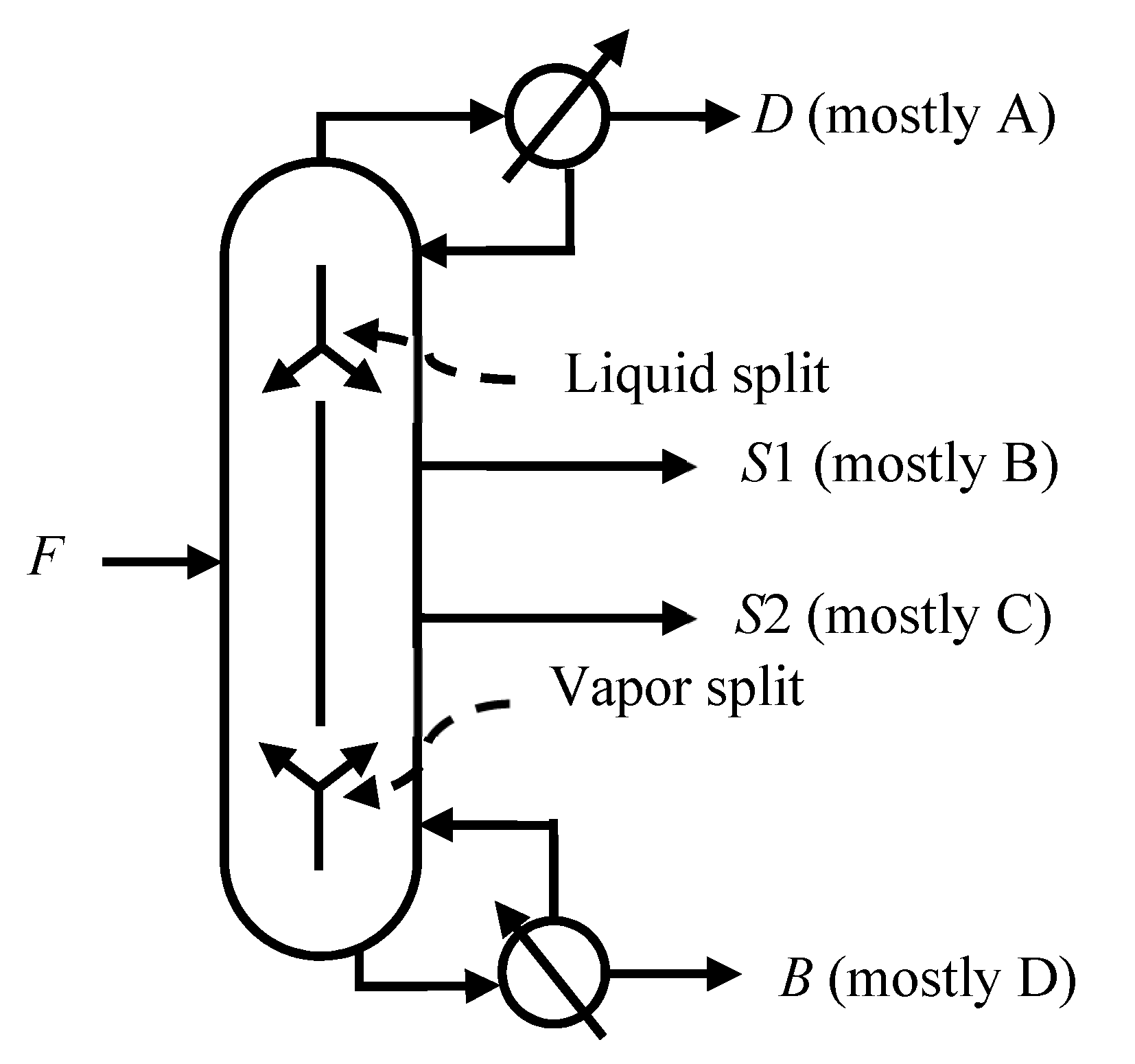
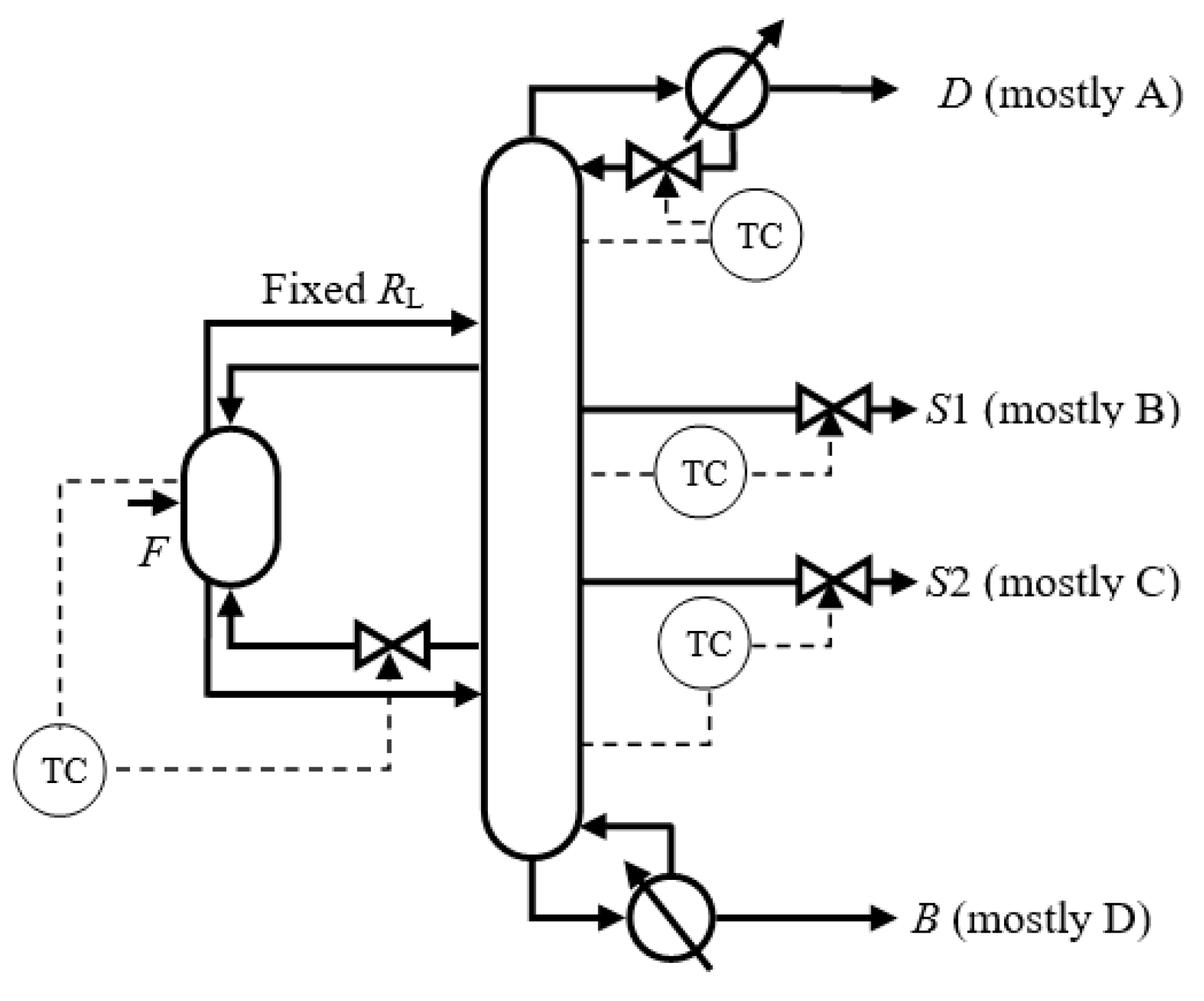
  • Liquid reflux stream for the prefractionator (Lp)
  • Vapor boilup stream for the prefractionator (Vp)
  • Reflux stream for the main column (L)
  • Reboiler duty for the main column (QR)
  • Upper side product stream of the main column (S1)
  • Lower side product stream of the main column (S2).
Small changes (+0.1%) in each available variable (u) were made one at a time to find the sensitive tray temperatures to control. Figure 3 shows the sensitivity analysis profiles. The y-axis with the label “Gains (K)” in Figure 3 represents the steady-state change in the temperature at every stage. For stabilizing the control of the distillation columns, one temperature control loop was used for each split [27]. The prefractionator carried out a sharp AB/CD split and required one temperature controller. The main column performed three sharp splits and required three temperature controllers. As shown in Figure 3, there was one sensitive temperature in the prefractionator and three sensitive temperatures in the main column. Therefore, the controlled variables in the temperature control structures were [TP,7, TM,6, TM,28, TM,53].
Singular value decomposition analysis was used for choosing reference temperatures and sensitive temperatures for the temperature difference control structures [12]. Singular value decomposition analysis profiles are shown in Figure 4. The formula [U,S,V] = svd (Gains,0) was used for SVD calculations. The y-axis with the label “U” in Figure 4 means the matrix U in the formula. In the temperature difference control structures, the controlled variables were temperature differences. In the prefractionator, it was the TD between the 19th and the 7th tray. In the main column, they were the TD between the 21st and the 6th tray, the TD between the 35th and the 28th tray, and the TD between the 53rd and the 48th tray. In summary, the controlled variables in the temperature difference control structures were [TP,19 − TP,7, TM,21 − TM,6, TM,35 − TM,28, TM,53 − TM,48], as shown in Figure 4a,b. Similarly, as shown in Figure 4c,d, the controlled variables in the double temperature difference control structures were [(TP,19 − TP,7) − (TP,7 − TP,2), (TM,21 − TM,6) − (TM,6 − TM,2), (TM,35 − TM,28) − (TM,28 − TM,22), (TM,60 − TM,53) − (TM,53 − TM,48)].
Lp was employed as the manipulated variable in TC1, TDC1, and DTDC1, while Vp was used as the manipulated variable in TC2, TDC2, and DTDC2. In the main column, L, S1, and S2 were used as manipulated variables according to the “pair close rule.” As shown in Figure 3 and Figure 4, S2 and QR were both available as manipulated variables. However, the side product flow rates should not stay constant when feed rate disturbances or feed composition disturbances occur. In other words, almost all of component C should flow into S2 eventually. Therefore, we used S2 as the manipulated variable and kept QR constant, as in the reported work by Dwivedi et al. [30]. In this way, we suppressed the excessive interactions among different control loops in the stripping section.

3.1. Temperature Control

Temperature control 1 (TC1) contained four temperature controllers, as illustrated in Figure 5. Rv was constant in TC1. For the temperature controller TCP, the manipulated variable (MV) was Lp in the prefractionator. The manipulated variables in the main column were L, S1, and S2. The corresponding controlled variables (CV) were [TP,7, TM,6, TM,28, TM,53].
The controller gains and integral time constants were calculated using the Tyreus−Luyben method through close-loop tuning. The tuning sequence was as follows: first of all, the L loop; second, the S1 loop; third, the S2 loop; and last, the Lp loop at the top of the prefractionator. The controllers tuning results of TC1 are presented in Table 1.
Temperature control 2 (TC2) is sketched in Figure 6. As the RV had been experimentally verified as a manipulated variable in alcohols systems in the Kaibel DWC [31], it is of significance to study the effectiveness of temperature control with the vapor split being the MV in other systems. RL was fixed in TC2. The tuning sequence of TC2 was similar with that of TC1 except that the Vp loop was used instead of the Lp loop. The tuning method of TC2 was the same as that of TC1. The tuning results for TC2 are listed in Table 2.

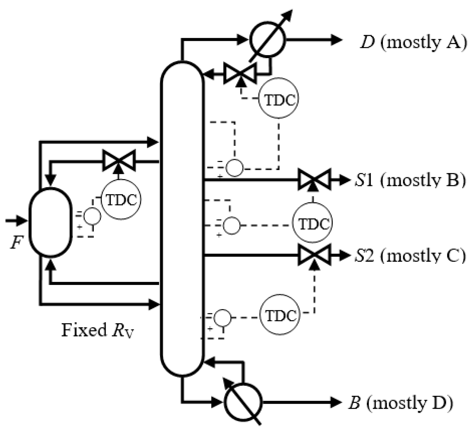
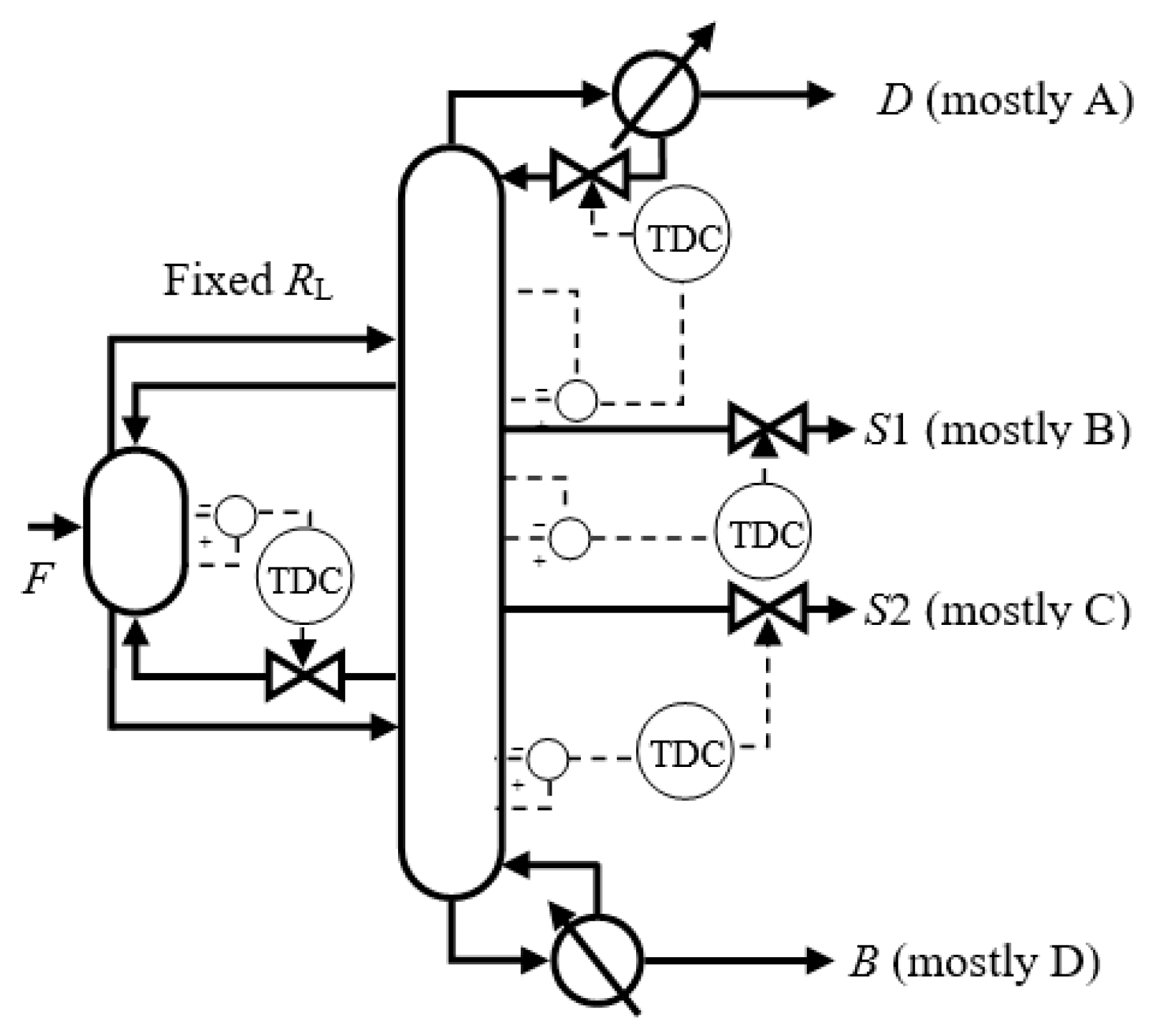
3.2. Temperature Difference Control

To reduce the interference of column pressure changes and improve the dynamic results, temperature difference control 1 (TDC1) and temperature difference control structure 2 (TDC2) were introduced. TDC1 is illustrated in Figure 7.
In TDC1, Lp was utilized to control the TD between the 19th and the 7th tray in the prefractionator. As for the main column, L was employed to control the TD between the 21st and the 6th tray, S1 was applied to control the TD between the 35th and the 28th tray, and S2 was utilized to control the TD between the 53rd and the 48th tray. RV remained constant in the operation. The tuning results for TDC1 are listed in Table 3.
Temperature difference control 2 (TDC2) is sketched in Figure 8. The difference between TDC2 and TDC1 was that Vp was employed as the manipulated variable for TDCP. In TDC2, RL remained constant. TDC2 was proposed in order to provide a possible control structure for the Kaibel DWC in the chemical industry. The tuning results for TDC2 are shown in Table 4.

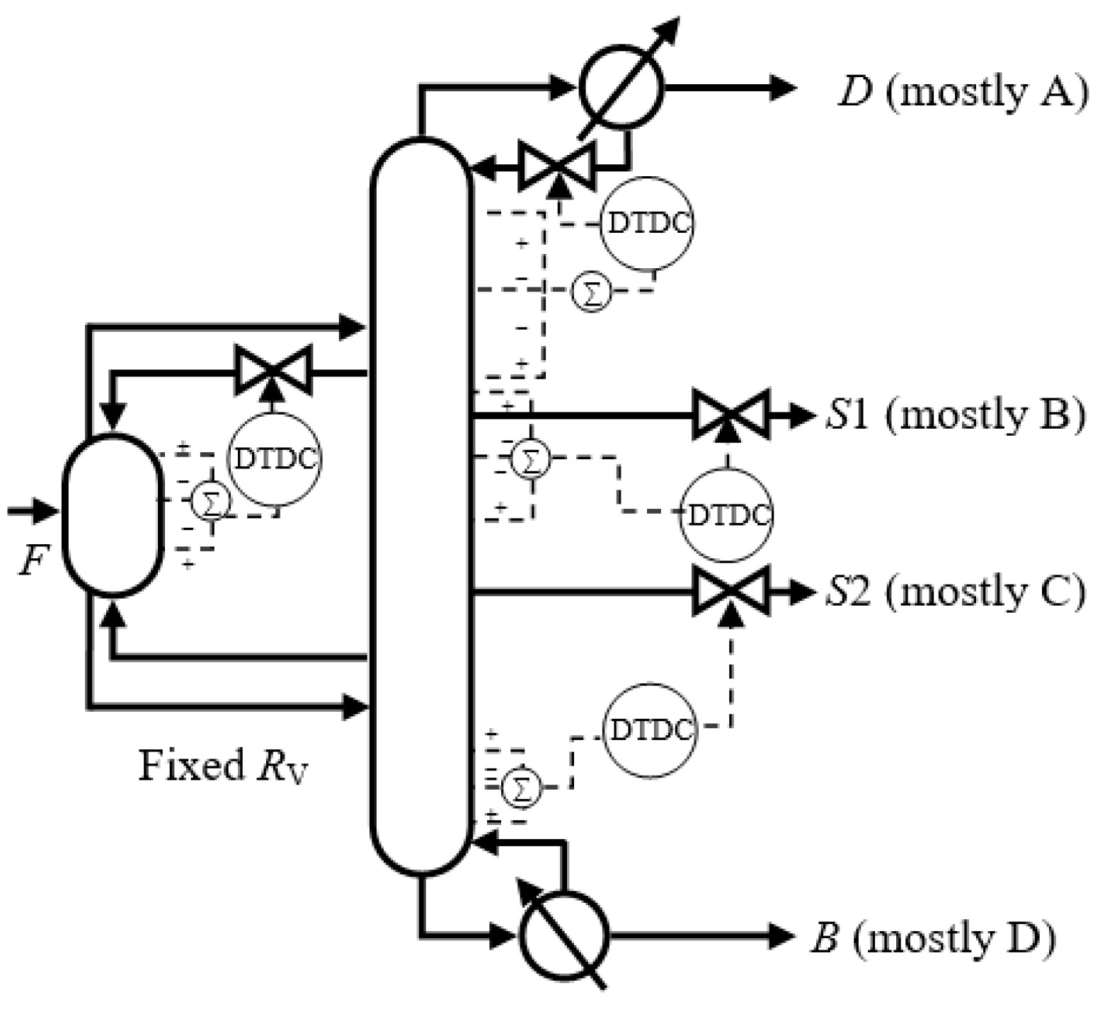
3.3. Double Temperature Difference Control

DTDC1, as shown in Figure 9, was introduced to achieve better results. In DTDC1, Lp was employed to control the double temperature difference [(TP,19 − TP,7) − (TP,7 − TP,2)] in the prefractionator. L, S1, and S2 were used to control the double temperature differences [(TM,21 − TM,6) − (TM,6 − TM,2)], [(TM,35 − TM,28) − (TM,28 − TM,22)], and [(TM,60 − TM,53) − (TM,53 − TM,48)] in the main column, respectively. RV was constant. The tuning results of DTDC1 are listed in Table 5.
DTDC2 is illustrated in Figure 10. The tuning results for TDC2 are shown in Table 6. The difference between DTDC2 and DTDC1 was that Vp was used as the MV for the double temperature difference controller DTDCP. RL was constant. As the manipulation of the vapor split in the Kaibel DWC has been experimentally verified, DTDC2 could be a promising method.

4. Results

The dynamic performances using TC and TDC against ±10% feed disturbances at 0.5 h are presented in Figure 11. Table 7, Table 8 and Table 9 show the steady-state deviation, maximum transient deviation, and settling time for the step disturbances in feed compositions and feed flow rates. For example, the +10% feed composition increase of A involved A increasing from 0.25 to 0.275, and the other three components were all equal. The positive responses are represented by black curves and negative responses by gray curves. The types of the line for black curves and gray curves are identical. Therefore, gray curves are not described in the legend in each figure in order to be concise and clear. The dynamic performances were all very smooth, although there were a few more oscillations when ±10% F disturbances occur. The steady-state and the maximum deviations (SD and MD) of the top product XD,A were smaller using temperature difference controls (TDC1 and TDC2) in most cases. For the bottom product XB,D, the SD and MD were reduced by employing temperature difference controls (TDC1 and TDC2) in all kinds of feed disturbances. Therefore, temperature difference control is a better choice if the top and the bottom products are more important than the side products. For the upper side product XS1,B, the SD and MD were suppressed using temperature control (TC1 and TC2) in most cases. Different from the other three products, the SD and MD of XS2,C were reduced by employing control structures with an active RL (TC1 and TDC1) in most cases. The SD and MD of the D and B were smaller than those of S1 and S2 because the product composition specifications were different.
As for DTDC, although the dynamic results for the upper side product using the control structures were similarly good, the dynamic performances for the lower side product using the control structures were very different. In order to be more clear, the dynamic performances of the four products using TDC and DTDC against ±10% feed disturbances at 0.5 h are presented in Figure 12. For the lower side product XS2,C, control structures with an active vapor split (TDC2 and DTDC2) were better when feed compositions of B or C occurred, while control structures with an active liquid split (TDC1 and DTDC1) were better when other feed disturbances occurred. The SD and MD of XS2,C were all larger than those of XS1,B. Also, the SD and MD of the bottom product were mostly larger than those of the top product. The reason for the inferiority of the lower side product and bottom product was the serious coupling in the stripping section. The SD and MD of the top product XD,A were reduced when employing control structures with an active RV (TDC2 and DTDC2). For the bottom product XB,D, the SD and MD were reduced when employing control structures with an active RL (TDC1 and DTDC1). Therefore, control structures with an active RL are the better choices if S2 and B are more important than D and S1. For the settling time, DTDC structures were best among the six control structures. For the deviations, this may be due to the fact that the sensitive temperatures could not accurately indicate the compositions in the multicomponent distillation systems. Besides, the pressure variations may aggravate the inconsistencies between the sensitive temperatures and the compositions. Pressure-compensated temperature difference control may be explored in the future to compensate for the pressure variations.

5. Conclusions

Two TC structures, two TDC structures, and two DTDC structures were proposed for the four-product Kaibel DWC in this paper. The TC1, TDC1, and DTDC1 employed a liquid split in the control structures, while TC2, TDC2, and DTDC2 used a vapor split in the control structures. The feasibility of the proposed six control structures was verified with a wide variety of feed disturbances. We used one temperature control loop for each split for the stabilizing control layer [27]. The prefractionator carried out the AB/CD split, so the prefractionator required one temperature controller, while the main column completed three sharp splits (including A/B, B/C, and C/D splits), therefore it required three temperature controllers. In summary, at least four temperature controllers were needed. Temperature difference control was a better choice if the top and the bottom products were more important than the side products. Temperature control (TC1 and TC2) was better if the upper side product was important, while the control structure with RL being the manipulated variable (TC1 and TDC1) was better if the lower side product was important. The dynamic performances of S2 and B were inferior to the dynamic performances of the top product and the upper side product because of the serious coupling in the stripping section. Control structures with active RL were satisfactory if S2 and B were more important than D and S1. For the settling time, DTDC structures were best among the six control structures. The performances were all very smooth, and the settling times were very short. This paper proves that traditional PI control with only temperature sensors were able to deal with disturbances put into the complicated Kaibel DWC, which is an encouraging outcome that helps to promote the industrialization of the Kaibel DWC.

Author Contributions

Conceptualization, X.Q.; methodology, X.Q.; software, R.L.; validation, X.Q. and R.L.; formal analysis, X.Q. and R.L.; investigation, X.Q. and R.L.; resources, X.Q.; data curation, X.Q. and R.L.; writing—original draft preparation, X.Q. and R.L.; writing—review and editing, K.H., H.C., Y.Y., L.Z., and S.W.; supervision, K.H.; project administration, X.Q., K.H., H.C., Y.Y., and L.Z.

Funding

This research was funded by the National Nature Science Foundation of China (grant numbers: 21808007, 21878011, 21676011, 21576014), Open Foundation of State Key Laboratory of Chemical Engineering (grant number: SKL-ChE-18B01), China Postdoctoral Science Foundation (grant numbers: 2017M620587, 2019M650453), and Fundamental Research Funds for the Central Universities (grant numbers: ZY1837, ZY1930).

Conflicts of Interest

The authors declare no conflict of interest. The funders had no role in the design of the study; in the collection, analyses, or interpretation of data; in the writing of the manuscript, or in the decision to publish the results.

References

  1. Kiss, A.A. Distillation technology-still young and full of breakthrough opportunities. J. Chem. Technol. Biotechnol. 2014, 89, 479–498. [Google Scholar] [CrossRef]
  2. Dejanovic, I.; Matijasevic, L.; Olujic, Z. Dividing wall column-A breakthrough towards sustainable distilling. Chem. Eng. Process. 2010, 49, 559–580. [Google Scholar] [CrossRef]
  3. Yildirim, O.; Kiss, A.A.; Kenig, E.Y. Dividing wall columns in chemical process industry: A review on current activities. Sep. Purif. Technol. 2011, 80, 403–417. [Google Scholar] [CrossRef]
  4. Triantafyllou, C.; Smith, R. The design and optimisation of fully thermally coupled distillation columns: Process design. Chem. Eng. Res. Des. 1992, 70, 118–132. [Google Scholar]
  5. Dejanovic, I.; Matijasevic, L.; Halvorsen, I.J.; Skogestad, S.; Jansen, H.; Kaibel, B.; Olujic, Z. Designing four-product dividing wall columns for separation of a multicomponent aromatics mixture. Chem. Eng. Res. Des. 2011, 89, 1155–1167. [Google Scholar] [CrossRef]
  6. Dejanovic, I.; Halvorsen, I.J.; Skogestad, S.; Jansen, H.; Olujic, Z. Hydraulic design, technical challenges and comparison of alternative configurations of a four-product dividing wall column. Chem. Eng. Process. 2014, 84, 71–81. [Google Scholar] [CrossRef]
  7. Kaibel, G. Distillation columns with vertical partitions. Chem. Eng. Technol. 1987, 10, 92–98. [Google Scholar] [CrossRef]
  8. Ghadrdan, M.; Halvorsen, I.J.; Skogestad, S. Optimal operation of Kaibel distillation columns. Chem. Eng. Res. Des. 2011, 89, 1382–1391. [Google Scholar] [CrossRef]
  9. Wolff, E.A.; Skogestad, S. Operation of integrated three-product (Petlyuk) distillation columns. Ind. Eng. Chem. Res. 1995, 34, 2094–2103. [Google Scholar] [CrossRef]
  10. Wang, S.-J.; Wong, D.S.H. Controllability and energy efficiency of a high-purity divided wall column. Chem. Eng. Sci. 2007, 62, 1010–1025. [Google Scholar] [CrossRef]
  11. Ling, H.; Luyben, W.L. New control structure for divided-wall columns. Ind. Eng. Chem. Res. 2009, 48, 6034–6049. [Google Scholar] [CrossRef]
  12. Ling, H.; Luyben, W.L. Temperature control of the BTX divided-wall column. Ind. Eng. Chem. Res. 2010, 49, 189–203. [Google Scholar] [CrossRef]
  13. Dwivedi, D.; Halvorsen, I.J.; Skogestad, S. Control structure selection for three-product Petlyuk (dividing-wall) column. Chem. Eng. Process. 2013, 64, 57–67. [Google Scholar] [CrossRef]
  14. Dwivedi, D.; Halvorsen, I.J.; Skogestad, S. Control structure selection for four-product Petlyuk column. Chem. Eng. Process. 2013, 67, 49–59. [Google Scholar] [CrossRef]
  15. Fan, G.; Jiang, W.; Qian, X. Comparison of stabilizing control structures for four-product Kaibel column. Chem. Eng. Res. Des. 2016, 109, 675–685. [Google Scholar] [CrossRef]
  16. Qian, X.; Jia, S.; Skogestad, S.; Yuan, X. Control structure selection for four-product Kaibel column. Comput. Chem. Eng. 2016, 93, 372–381. [Google Scholar] [CrossRef]
  17. Jia, S.; Qian, X.; Yuan, X. Optimal design for dividing wall column using support vector machine and particle swarm optimization. Chem. Eng. Res. Des. 2017, 125, 422–432. [Google Scholar] [CrossRef]
  18. Jia, S.; Qian, X.; Yuan, X.; Skogestad, S. Control structure comparison for three-product Petlyuk column. Chin. J. Chem. Eng. 2018, 26, 1621–1630. [Google Scholar] [CrossRef]
  19. Kiss, A.A.; Ignat, R.M. Innovative single step bioethanol dehydration in an extractive dividing-wall column. Sep. Purif. Technol. 2012, 98, 290–297. [Google Scholar] [CrossRef]
  20. Kiss, A.A.; Suszwalak, D. Enhanced bioethanol dehydration by extractive and azeotropic distillation in dividing-wall columns. Sep. Purif. Technol. 2012, 86, 70–78. [Google Scholar] [CrossRef]
  21. Le, Q.-K.; Halvorsen, I.J.; Pajalic, O.; Skogestad, S. Dividing wall columns for heterogeneous azeotropic distillation. Chem. Eng. Res. Des. 2015, 99, 111–119. [Google Scholar] [CrossRef]
  22. Luyben, W.L. Improved plantwide control structure for extractive divided-wall columns with vapor recompression. Chem. Eng. Res. Des. 2017, 123, 152–164. [Google Scholar] [CrossRef]
  23. Staak, D.; Grutzner, T. Process integration by application of an extractive dividing-wall column: An industrial case study. Chem. Eng. Res. Des. 2017, 123, 120–129. [Google Scholar] [CrossRef]
  24. Delgado-Delgado, R.; Hernandez, S.; Barroso-Munoz, F.O.; Segovia-Hernandez, J.G.; Castro-Montoya, A.J. From simulation studies to experimental tests in a reactive dividing wall distillation column. Chem. Eng. Res. Des. 2012, 90, 855–862. [Google Scholar] [CrossRef]
  25. Feng, S.; Ye, Q.; Xia, H.; Li, R.; Suo, X. Integrating a vapor recompression heat pump into a lower partitioned reactive dividing-wall column for better energy-saving performance. Chem. Eng. Res. Des. 2017, 125, 204–213. [Google Scholar] [CrossRef]
  26. Kiss, A.A.; Suszwalak, D. Innovative dimethyl ether synthesis in a reactive dividing-wall column. Comput. Chem. Eng. 2012, 38, 74–81. [Google Scholar] [CrossRef]
  27. Skogestad, S. The Dos and Don’ts of Distillation Column Control. Chem. Eng. Res. Des. 2007, 85, 13–23. [Google Scholar] [CrossRef]
  28. Luyben, W.L. Distillation Design and Control Using Aspen Simulation; John Wiley & Sons: New York, NY, USA, 2013. [Google Scholar]
  29. Luyben, W.L.; Chien, I.L. Design and Control of Distillation Systems for Separating Azeotropes; John Wiley & Sons: New York, NY, USA, 2011. [Google Scholar]
  30. Dwivedi, D.; Strandberg, J.P.; Halvorsen, I.J.; Skogestad, S. Steady state and dynamic operation of four-product dividing-wall (Kaibel) Columns: Experimental verification. Ind. Eng. Chem. Res. 2012, 51, 15696–15709. [Google Scholar] [CrossRef]
  31. Dwivedi, D.; Strandberg, J.P.; Halvorsen, I.J.; Preisig, H.A.; Skogestad, S. Active vapor split control for dividing-wall columns. Ind. Eng. Chem. Res. 2012, 51, 15176–15183. [Google Scholar] [CrossRef]
Figure 1. Kaibel dividing wall column (Kaibel DWC).
Processes 07 00773 g001
Figure 2. Thermally coupled configuration of the Kaibel DWC.
Processes 07 00773 g002
Figure 3. Sensitivity analysis profiles: (a) prefractionator; (b) main column.
Processes 07 00773 g003
Figure 4. Singular value decomposition analysis profiles: (a) temperature difference for the prefractionator; (b) temperature difference for the main column; (c) double temperature difference for the prefractionator; (d) double temperature difference for the main column.
Processes 07 00773 g004
Figure 5. Temperature control 1 (TC1).
Processes 07 00773 g005
Figure 6. Temperature control 2 (TC2).
Processes 07 00773 g006
Figure 7. Temperature difference control 1 (TDC1).
Processes 07 00773 g007
Figure 8. Temperature difference control 2 (TDC2).
Processes 07 00773 g008
Figure 9. Double temperature difference control 1 (DTDC1).
Processes 07 00773 g009
Figure 10. Double temperature difference control 2 (DTDC2).
Processes 07 00773 g010
Figure 11. TC versus TDC: Dynamic results against ±10% feed compositions and feed flow rate (F) disturbances: (a) A disturbances, (b) B disturbances, (c) C disturbances, (d) D disturbances, and (e) F disturbances.
Processes 07 00773 g011aProcesses 07 00773 g011bProcesses 07 00773 g011c
Figure 12. TDC versus DTDC: Dynamic results against ±10% feed compositions and feed flow rate (F) disturbances: (a) A disturbances, (b) B disturbances, (c) C disturbances, (d) D disturbances, and (e) F disturbances.
Processes 07 00773 g012aProcesses 07 00773 g012bProcesses 07 00773 g012c
Table 1. Controllers tuning results of TC1.
LoopCVMVGainIntegral Time (min)
TCPTP,7Lp0.37817.16
TCM1TM,6L0.3169.24
TCM2TM,28S14.84613.20
TCM3TM,53S24.91519.80
Table 2. Controllers tuning results of TC2.
LoopCVMVGainIntegral Time (min)
TCPTP,7Vp0.81710.56
TCM1TM,6L0.31710.56
TCM2TM,28S13.29317.16
TCM3TM,53S24.54119.80
Table 3. Controllers tuning results of TDC1.
LoopCVMVGainIntegral Time (min)
TDCPTP,19 − TP,7Lp0.33914.52
TDCM1TM,21 − TM,6L0.2079.24
TDCM2TM,35 − TM,28S13.90210.56
TDCM3TM,53 − TM,48S22.41615.84
Table 4. Controllers tuning results of TDC2.
LoopCVMVGainIntegral Time (min)
TDCPTP,19 − TP,7Vp0.64811.88
TDCM1TM,21 − TM,6L0.182 9.24
TDCM2TM,35 − TM,28S13.36711.88
TDCM3TM,53 − TM,48S22.47319.80
Table 5. Controllers tuning results of DTDC1.
LoopCVMVGainIntegral Time (min)
DTDCP(TP,19 − TP,7) − (TP,7 − TP,2)Lp0.07314.52
DTDCM1(TM,21 − TM,6) − (TM,6 − TM,2)L0.0409.24
DTDCM2(TM,35 − TM,28) − (TM,28 − TM,22)S10.39611.88
DTDCM3(TM,60 − TM,53) − (TM,53 − TM,48)S20.22114.52
Table 6. Controllers tuning results of DTDC2.
LoopCVMVGainIntegral Time (min)
DTDCP(TP,19 − TP,7) − (TP,7 − TP,2)Vp0.10910.56
DTDCM1(TM,21 − TM,6) − (TM,6 − TM,2)L0.0409.24
DTDCM2(TM,35 − TM,28) − (TM,28 − TM,22)S10.37510.56
DTDCM3(TM,60 − TM,53) − (TM,53 − TM,48)S20.22814.52
Table 7. Steady-state deviations of the four products (ΔXDA, ΔXS1B, ΔXS2C, ΔXBD).
DisturbanceProductTC1 (%)TC2 (%)TDC1 (%)TDC2 (%)DTDC1 (%)DTDC2 (%)
+10% AA−0.062−0.062−0.063−0.068−0.065−0.068
B−0.073−0.073−0.047−0.061−0.048−0.058
C0.7940.8920.8050.8950.7960.887
D0.0250.0080.0020.0010.0160.014
−10% AA0.0590.0590.0590.0620.0610.063
B0.0690.0710.0380.0490.0430.051
C−1.045−1.210−1.071−1.221−1.050−1.201
D−0.024−0.008−0.0010.000−0.015−0.013
+10% BA0.0210.0220.0210.0460.0220.035
B0.1130.1300.1350.2150.1160.183
C0.807−0.0860.8160.0340.8100.018
D0.0230.1220.0020.0140.0160.033
−10% BA−0.022−0.023−0.020−0.049−0.022−0.037
B−0.147−0.138−0.175−0.254−0.154−0.212
C−1.0650.058−1.089−0.061−1.073−0.043
D−0.019−0.146−0.001−0.014−0.014−0.034
+10% CA0.0210.0200.0200.0090.0210.015
B−0.029−0.030−0.070−0.106−0.054−0.082
C−1.990−1.507−1.924−1.509−1.959−1.540
D0.046−0.0030.004−0.0010.0270.019
−10% CA−0.021-0.021−0.019−0.008−0.021−0.015
B0.0240.0290.0470.0880.0400.071
C1.4271.2961.4181.2931.4221.301
D−0.0400.007−0.0030.002−0.024−0.018
+10% DA0.0180.0180.0210.0100.0210.015
B−0.033−0.034−0.043−0.079−0.038−0.065
C0.2680.6480.1930.5520.2410.595
D−0.093−0.148−0.004−0.009−0.058−0.066
−10% DA−0.018−0.017−0.020−0.009−0.020−0.014
B0.0280.0320.0450.0790.0370.064
C−0.116−0.531−0.044−0.393−0.087−0.448
D0.0870.1270.0110.0150.0570.064
+10% FA−0.068−0.066−0.060−0.023−0.067−0.046
B0.0470.075−0.0390.0710.0260.118
C−3.319−5.154−3.419−4.949−3.349−4.884
D−0.0580.093−0.0030.013−0.042−0.016
Table 8. Maximum transient deviations of the four products (ΔXDA, ΔXS1B, ΔXS2C, ΔXBD).
DisturbanceProductTC1 (%)TC2 (%)TDC1 (%)TDC2 (%)DTDC1 (%)DTDC2 (%)
+10% AA−0.062−0.064−0.063−0.075−0.065−0.069
B−0.138−0.333−0.119−0.251−0.167−0.218
C0.7940.8920.8050.8950.7960.887
D0.0810.1020.0650.0710.0610.064
−10% AA0.0590.0610.0590.0690.0610.064
B0.1230.3140.1030.2410.1760.223
C−1.045−1.210−1.071−1.221−1.050−1.201
D−0.102−0.131−0.081−0.089−0.077−0.082
+10% BA−0.022−0.057−0.0220.0640.0220.043
B0.4770.7300.4090.6340.4800.662
C0.807−0.1870.8160.1430.8100.168
D0.0910.2060.0730.0810.0790.089
−10% BA−0.0220.0550.022−0.072−0.022−0.045
B−0.507−0.761−0.417−0.672−0.519−0.664
C−1.0650.158−1.089−0.164−1.073−0.191
D−0.109−0.293−0.088−0.119−0.095−0.129
+10% CA0.0210.0210.020−0.0200.0210.017
B−0.190−0.296−0.192−0.290−0.221−0.280
C−1.990−1.507−1.924−1.509−1.959−1.540
D−0.161−0.252−0.165−0.189−0.138−0.150
−10% CA−0.021−0.021−0.0190.020−0.021−0.016
B0.1860.2800.1890.2770.2140.280
C1.4271.2961.4181.2931.4221.301
D0.0980.1530.1080.1190.0890.091
+10% DA0.0210.0210.0220.0160.0210.017
B−0.184−0.261−0.123−0.214−0.180−0.228
C0.2720.6480.1960.5520.2440.595
D−0.095−0.1500.0370.043−0.059−0.066
−10% DA−0.020−0.022−0.021−0.017−0.020−0.016
B0.1760.2500.1210.2050.1720.222
C−0.122−0.5310.172−0.3930.149−0.448
D0.0880.128−0.033−0.0380.0570.065
+10% FA0.073−0.0700.0760.081−0.067−0.053
B0.5730.9120.5620.8810.6390.899
C−3.319−5.187−3.419−5.014−3.349−5.109
D−0.410−0.218−0.349−0.252−0.576−0.371
Table 9. Settling time of the four products (XDA, XS1B, XS2C, XBD).
DisturbanceProductTC1TC2TDC1TDC2DTDC1DTDC2
+10% AA1.261.241.281.191.071.06
B1.082.211.062.231.002.18
C3.363.113.343.043.393.09
D1.331.411.251.131.161.00
−10% AA1.241.241.241.181.041.04
B1.092.211.092.241.012.21
C3.833.053.703.063.692.97
D1.431.441.321.761.241.62
+10% BA1.131.301.121.750.910.93
B1.272.571.062.631.112.65
C3.242.063.191.983.162.63
D1.401.981.311.901.212.17
−10% BA1.171.331.121.810.910.94
B1.402.151.122.501.242.53
C3.342.073.322.053.291.81
D1.522.031.381.971.281.82
+10% CA1.121.311.121.320.861.03
B1.341.980.861.971.052.00
C3.092.702.992.772.922.60
D1.992.031.842.121.711.49
−10% CA1.141.361.121.330.881.09
B1.302.030.931.981.052.40
C3.013.243.153.203.073.28
D1.781.751.691.941.551.37
+10% DA0.760.590.800.110.710.58
B1.221.901.441.971.222.01
C2.473.062.543.102.523.21
D2.092.112.042.181.901.85
−10% DA0.750.580.77−0.030.700.57
B1.191.981.191.631.142.04
C1.972.391.852.291.802.38
D2.092.072.032.111.871.83
+10% FA1.441.461.431.801.241.34
B1.482.581.632.631.183.08
C3.413.803.303.513.173.33
D1.693.462.423.362.562.97

