Flexible Energy Storage System—An Introductory Review of Textile-Based Flexible Supercapacitors


1
Institute of Textiles & Clothing, The Hong Kong Polytechnic University, Hong Kong, China
2
Department of Applied Physics, The Hong Kong Polytechnic University, Hong Kong, China
*
Author to whom correspondence should be addressed.
Processes 2019, 7(12), 922; https://0-doi-org.brum.beds.ac.uk/10.3390/pr7120922
Submission received: 5 November 2019
/
Revised: 25 November 2019
/
Accepted: 2 December 2019
/
Published: 4 December 2019
(This article belongs to the Special Issue Green Sustainable Chemical Processes)
Abstract
:Recently, researchers have become interested in exploring applications of rechargeable battery storage technology in different disciplines, which can help our daily life, such as textile-based supercapacitors. This paper briefly describes this development and classification of supercapacitors. Besides, various types of materials which are commonly used to prepare supercapacitors, such as carbons, metal oxides, alkaline earth metal salts and polymers, are introduced. Moreover, applications and methodology to prepare textile materials with supercapacitors are described. Finally, the commonly used non-destructive measuring methods for textile-based supercapacitors are also introduced.
1. Introduction
In recent years, significant effort has been committed to alternative energy storage/conversion devices development with high energy and power densities due to the increase of environmental problems and the continuing depletion of fossil fuels. As an intermediate system between batteries and dielectric capacitors, supercapacitors have attracted an extensive attention owing to their higher power densities relative to secondary batteries. Furthermore, they are maintenance-free, have a longer life cycle, can cope with a simple charging circuit, suffer no memory effects and are generally safer to be used. A physical method rather than chemical method for energy storage is the crucial reason why they are operationally more safe, and have an exceptionally long life cycle. The most important is that supercapacitors can perform a high rate of charging and discharging [1,2,3]. There are two energy storage mechanisms in supercapacitors: the electrical double-layer (EDL) capacitance and the pseudocapacitance. Currently, EDL capacitors consist of activated carbon (AC) with higher surface area used as the electrode material, and the capacitance comes from charges which are accumulated at the interface between the electrode and the electrolyte. In contrast, a pseudocapacitor applies conducting polymers or metal oxides as the electrode material, with which reversible Faradic redox reactions occur. Conducting polymers, such as polyanilines, with an exhibition of high pseudocapacitance, have been shown [4,5,6].
Besides, the conducting fibers, the so-called “electro-textiles (e-textiles)”, have appeared as promising materials for wearable and flexible applications. Since they are lightweight, durable and bendable, they have become popular, and are being widely applied in textile products, such as in functional clothes with variable sensors for medical monitoring accessories. Recently, techniques of metal coating on fabrics like conductive paints and lacquers, vacuum deposition, sputter coating, flame and arc spraying and electroless plating, have been used.
Between these methods, electroless plating is the most preferred way to prepare metal-coated textiles. This technique is preferred because a coherent metal deposition and excellent conductivity can be easily obtained. Besides, it is applicable to different complex-shaped materials or non-conducting substrates, therefore it can be applied to nearly all kinds of fiber substances. This plating can be done at any stage during textile production, such as fiber, yarn, fabric and garment [7].
In this paper, fabric-based supercapacitors are discussed in terms of material characteristics, preparation methods and characterization methods.
1.1. Historical Development of Supercapacitors
Many types of methods and elements can be used for energy storage, where capacitors are one of the fundamental electrical circuit elements [8]. From the simplest electrostatic capacitors to electrolytic capacitors, and then the supercapacitors, capacitance has been increased from milli-Farad (mF) to hundreds or even thousands of Farads (F), and the efficiency and effectiveness of the capacitors have also been improved [9].
The first supercapacitor was the Leyden jar. In 1746, a double-layer supercapacitor was made at Leyden in the Netherlands by Pieter van Musschenbroek. It was found that electrical charges can be stored on the plates in the set-up, and the so-called condenser was connected with a capacitor in the mechanism of electrostatics. Nevertheless, the first patent was registered only in 1957 when a capacitor based on carbon with a high surface area was illustrated [10].
The electrolytic capacitor was then developed and commercialized, a polarized capacitor wherein conductive electrolyte salt interacts with metal electrodes. Practically, two metal foils coated with an insulating oxide layer were sandwiched with an electrolyte-soaked paper spacer. The thin oxide layers on electrodes performed as dielectric elements, providing higher capacitance per unit volume compared to the electrostatic capacitors. Aluminum, tantalum, niobium and niobium oxides were commonly used for manufacturing electrolytic capacitors, with relative permittivity varying from 9.6 to 41, and capacitance ranging from a few μF to tens of mF, or even in some extreme cases, hundreds of mF [8,11]. Some key issues on capacitor development are shown in Figure 1.
Compared with the traditional simple electrostatic and electrolytic capacitors, supercapacitors give tens to hundreds times higher in specific energy. Besides, supercapacitors can provide higher specific power than many types of batteries, where the specific energy of supercapacitors is relatively lower than the batteries [12]. A comparison of the characteristics of a typical capacitor and battery is shown in Table 1.
Supercapacitors are said to be the key for bridging the gap between the two energy storage devices, batteries and capacitors, and to establish fast charging energy-storage devices and providing intermediate specific energy. Due to the fact that their charge-storage process is highly reversible, supercapacitors have relatively longer life-cycles and can exhibit rapid responses in both the charging and discharging process. This results in considerable interest in its application in various consumer electronics, industrial power management systems and hybrid vehicles with electric and fossil fuel [9,12].
1.2. Nomenclature of Supercapacitors
Practically, supercapacitors are divided into three different categories, as shown in Figure 2, which are classified in terms of their charging mechanisms: (a) double layer capacitors; (b) pseudocapacitors; and (c) hybrid capacitors.
Double layer capacitors constitute an energy storage system that contains two layers of polarizing electrodes sandwiched between a separator and filled with electrolytes [8]. The energy can be kept in the form of an electrostatic mechanism.
In pseudocapacitors, energy is stored through the bulk of redox material in the context of redox reactions, where the fast chemical reaction serves like capacitance [9].
In hybrid capacitors, substances like active carbon, conducting polymers, or even transitional metal oxides, are doped or added to the electrodes, provided that the capacitors can exhibit both electrostatic responses and reversible Faradaic-type charge transfer, where the lithium-ion capacitor is a typical example in this category.
2. Energy Storage Mechanism in Supercapacitors
Generally speaking, two different working principles are applied for keeping energy in supercapacitors: (1) the double-layer capacitance, or the so-called electrical/electrochemical double-layer capacitance (EDLC), and (2) the pseudocapacitance; their working mechanisms are described in the following.
2.1. Electrical Double-Layer Capacitance (EDLC)
In double-layer capacitance, energy is stored in a method similar to the traditional parallel capacitor through charge separation. Nevertheless, it can keep considerably more energy than a classic capacitor. Since the charge separation arises across a relatively small distance in case of an electrical double layer, the interphase can be set up between a particular electrode and its adjacent electrolyte. Moreover, a higher amount of energy can be kept on the electrode with a large surface area, which is provided by a large number of pores. This energy storage mechanism can respond rapidly because a simple movement of ions that migrate to and escape from electrode surfaces is involved, as shown in Figure 3 [9,10,12].
2.2. Pseudocapacitance
In pseudocapacitance, a relatively large capacitance under a non-electrostatic basis is found, which is due to a reversible Faradaic-type charge transfer taking place. Moreover, with a limited amount of active materials or effective surfaces, capacitance related to an electrochemical charge-transfer process is produced. Recently, the prominent pseudocapacitive materials being investigated are transition metal oxides, such as manganese (II) oxide (MnO2), and conducting polymers like Polypyrrole (Ppy), Polyaniline (PAni), or derivatives of Polythiophene (PTh) (e.g., Poly(3,4-ethylenedioxythiophene), PEDOT). Since the energy storage mechanism in this type of supercapacitor is grounded on a redox process, and it has a somewhat battery-like behavior, this pseudocapacitor is also referred to as a redox supercapacitor, carrying out a typical charge transferring process of Cl− ions in a conducting polymer matrix, as illustrated in Figure 4 [9,10,12].
3. Electrode Materials
Supercapacitors can be fabricated from a wide diversity of materials, such as carbon materials, conducting polymers and metal oxides, the selection depending upon the type of capacitance, or in other words, the storage mechanism to be utilized. For double-layer capacitance, carbon materials are usually used, and for pseudocapacitance, metal oxides and conducting polymers have been applied frequently. Hence, for capacitors that exhibit both types of capacitance, composites of carbon with either metal oxides or conducting polymers are used.
3.1. Carbon Materials
Carbon materials are used to prepare supercapacitor electrodes because of their high conductivity and compatibility with other materials for making composite materials, and the controlled pores structure provides a higher surface area (~1 to >2000 m2/g) [12].
There are four crystalline allotropes in carbon: diamond (sp3 bonding), graphite (sp2), carbyne (sp1) and fullerenes (the so-called “distorted sp2”), where graphite and diamond are found naturally and the other two are synthetic. Recently, researchers focus upon graphite and fullerene to apply them to electrode materials in an electrochemical system because of their structures and functionalities. From graphite, a single layer of carbon atoms, graphene, can be extracted out, which is one of the popular candidates to dope into the electrochemical system. With its planar structure, a high electron mobility can be obtained, which can enhance the electronic response, and hence the electrical performance of these supercapacitors. Fullerene is usually in the form of a hollow sphere, ellipsoid, or cylindrical, such as carbon nanotubes. Carbon materials commonly used in supercapacitors are categorized based on their characteristics, for instance, activated carbons, carbon fibers and carbon nanotubes (CNT).
Activated carbons like carbon black are a group of materials characterised by almost spherical carbon particles of colloidal size, which can be produced by processes like thermal decomposition or a partial combustion of hydrocarbons in the gas phase. The crucial properties of carbon blacks are accounted to be fineness (primary particle size), porosity, structure (aggregate size/shape) and surface chemistry. This conductivity of carbon black typically ranges from 10−1 to 102 (Ω cm−1); it is being affected by electron tunneling, which is the relative ability of electrons to jump the gap between closely-spaced aggregates, and via touching aggregates, by graphitic conduction [12,13].
Typically, the diameter of carbon fibers is about 10 μm; they are mainly microporous (<2 nm) and have a very tight pore-size distribution. Because of its tiny structures, the porosity of carbon fibers is mainly located at the surface, and this therefore provides good approachability to active sites. Therefore, the diameter and length of the pores can be more easily regulated in carbon fibers. These features make carbon fibers a very attractive electrode material for energy storage devices, since both high adsorption rates and adsorption capacities are achievable [12].
To obtain the advantages of both activated carbons and carbon fibers, a new hybrid of these two materials, that is, activated carbon fibers (ACFs), is produced. ACFs are porous carbons in a fiber-like structure, and the aspect ratio of this structure is higher than 10, with an explicit porous structure which has high adsorption capacity. Generally, to obtain a high porosity to fulfill the requirements of specific applications, ACFs can be prepared from carbon fibers by heat treatment. With this structure, a humongous surface area of about 2000 m2g−1 can be obtained. ACFs gain the benefits of excellent volumetric capacity and high packing density, which shows its significance and usefulness for adsorption applications. Common activated carbons, due to their ladder-like structure, let the adsorbate gas molecules pass through macropores in the beginning, and then the mesopores before entering the micropores. In ACFs, adsorbate gas can contact with a large number of micropores on the fibers’ surface by the shortest route, so the adsorption mechanism can be largely improved [14,15].
The nanoscale tubular morphology of the CNT can provide high porosity and low electrical resistivity in a readily obtainable structure. As electrode materials, single-walled (SWNT) and multi-walled nanotubes (MWNT) have been investigated in both aqueous and non-aqueous electrolytes [12,13]. The specific capacitance typically ranges from 15–80 Fg−1 with a surface area in range of 120–400 m2g−1. The CNT surface area is mainly “mesoporous”, and is coupled with the outermost of the tubes. By subsequent oxidative treatment which can alter the surface morphology of the CNT, additional surface area is produced and the specific capacitance can be raised to about 130 Fg−1, which is a competent contributing to pseudocapacitance [12].
3.2. Metal Oxides
Transition metal oxides/hydroxides like ruthenium (Ru), cobalt (Co), manganese (Mn) and nickel (Ni) oxides/hydroxides are commonly applied in various supercapacitor applications. These conducting or semi-conducting transition metal oxides perform redox active behaviors, provided that pseudocapacitance does occurs. In 1971, ruthenium dioxide as a new electrode material was firstly reported, and then ruthenium oxide being a capacitive material has been determined extensively [16]. With reversible redox reactions in different aqueous media (e.g., Ru2+, Ru3+ and Ru4+ couples) and metallic-type conductivity, RuO2 is utilized in the supercapacitors extensively. The oxide can provide relatively steady and considerable capacitance at a potential towards 1.2 V, with specific capacitance between 600–1000 Fg−1, relying on various factors such as procedures for preparation, measurement conditions and use of support [17]. Another considerable benefit is the extremely high stability or long life-cycle. Thermally-formed RuO2 films on titanium with its oxides derivatives (TiO2 or Ti2O5) can be charged more than 105 times between 0.02–1.2 V, or with a slight degradation if the potential has been increased to 1.4 V. However, the cost of using ruthenium oxide is relatively high, and therefore these supercapacitor materials are mainly utilized in aerospace or military applications [18]. Therefore, for commercial, low-cost applications, other metal oxides like Co3O4 [19,20], NiO [21,22], and MnO2 [23,24] have been synthesized and examined for further supercapacitor applications. Though these metal oxides are relatively cost effective compared to ruthenium oxide, their specific capacitance is lower, typically within the range of 20–200 Fg−1. Besides, other electrical properties such as conductivity and potential window are relatively low compared to ruthenium oxide [10].
3.3. Conducting Polymers
Conducting polymers like Polypyrrole (Ppy), Polyaniline (PAni) or derivatives of Polythiophene (PTh) (e.g., Poly(3,4-ethylenedioxythiophene), PEDOT) are suitable to prepare for supercapacitors because these candidates can provide good electrical conductivity, which can also provide large pseudocapacitance, and at a relatively low cost.
Electrical properties like electrochemical capacitance and charge storage are being examined by electrochemical impedance spectroscopy (EIS), cyclic voltammetry (CV) and chronopotentiometry. Compared to ruthenium oxides, the specific capacitance of conducting polymers is compatible to oxides with 480 Fg−1 for Ppy, 775 Fg−1 for PAni and 210 Fg−1 for PEDOT [25,26,27]. Nonetheless, the poor mechanical stability of conducting polymers, which is attributed to repeated intercalation and to ions depletion during the process of charging and discharging, is the weakness of these materials [10]. Supercapacitors consist of only conducting polymers, and can be configured into the following three types: For Type (I), which are symmetric and use the same type of p-dopable polymer to prepare for both electrodes; for Type (II), which are asymmetric and use two different type of p-dopable polymers with a different range of electroactivity to prepare for electrodes; and for Type (III), which are symmetric and use the same type of polymer to prepare for both electrodes, with the p-doped form and n-doped form used as the positive electrode and negative electrode, respectively [28,29,30,31,32]. Structures of various conducting polymers are illustrated in Figure 5.
3.3.1. Polyaniline (PAni)
PAni exhibits a high doping level and high electroactivity, with excellent environmental stability, and can provide a high specific capacitance. Moreover, PAni has a controllable electrical conductivity (nearly 0.1 Scm−1 with a lithium dopant in the doped state), and it can be easily processed [9]. However, for a proper charging and discharging process, PAni needs a proton, and therefore an acidic solution, a protic solvent, or an ionic liquid, is required [33].
PAni has been studied to have a capacity in a range of 44–270 mAhg−1 [9]. This capacity variation may be due to the amount and type of additives and binders which have been used, the morphology of the polymer, the synthetic route employed and the electrode thickness. Compared to all conducting polymers, PAni has the most volatile specific capacitance, where the specific capacitance achieved from the electrodeposited PAni is higher than that prepared from chemically-formed PAni [9]. Moreover, the life-cycle of PAni for a positive electrode being Li-doped has been reported to be over 5000 cycles, with a reduction of specific capacitance from 100 to 70 Fg−1. Some studies have reported a reduction of specific capacitance from 107 to 84 Fg−1 when PAni is doped with LiPF6 after 9000 cycles [28,34].
Reporting by Park et al. [35], a device with PAni and carbon as the positive and negative electrode, respectively, has been made, which is the so-called hybrid electrochemical capacitor. This capacitor can provide comparable or even better performance than the Type (III) supercapacitors being reported before, which were made from PTh derivatives. A charge–discharge test with constant current at 0.5 mAcm−1 gives 380 Fg−1, where the specific energy and specific power at 20 mAcm−1 are 18 Whkg−1 and 1.25 kWkg−1, respectively. By cyclic voltammetry, a life-cycle of 4000 was observed, and the capacitor exhibits charge and discharge among 1.25–1.5 V and 1.4–1.0 V, respectively.
In PAni, the sites for proton exchange are hindered by methyl groups and, therefore it can stabilize and resist to chemical degradation and provide more redox reaction. If a lithium negative electrode is accompanied with PAni, a capacity of 52 mAhg−1 can be achieved [9].
3.3.2. Polypyrrole (Ppy)
In electrochemical processing, Ppy provides a larger degree of flexibility than many conducting polymers, and therefore, many researches about applying Ppy to battery or supercapacitor electrodes have been reported [9]. However, Ppy is not in favor of n-doped materials like those thiophene derivatives, so Ppy can only be found in the application of cathode materials.
Since the density of Ppy is larger, a higher capacitance per unit volume (400–500 Fcm−3) can be provided [9]. However, due to this density growth, the dopant ions are hindered, and not easy to access the interior sites of the polymer. As a result, capacitance per gram is decreased, particularly when there are thick coatings on electrodes [36]. Reported by Suematsu, Ppy is usually doped with anions which are single-charged, like SO3−, Cl− and ClO4−; however, if it is doped with anions which are multiple-charged, like SO42−, a physical cross-linking of polymers occurs. Moreover, high capacitance and high diffusivity are observed from these cross-linked materials, probably due to the increase of porosity [37].
Ppy can be applied to become an electrode to prepare for the Type (I) supercapacitor, and for our Type (II) device, poly (3-methyl thiophene) is added [30]. This Type (I) supercapacitor provides a capacitance of 8–15 mFcm−2 during discharging, which is more or less the same as Type (II). In Type (I), voltage is in the range of 0.5–1.0 V, which goes up to 1.2 V for Type (II). With a polymer electrolyte that is PVA-based, Ppy can be utilized to fabricate an all solid-state-supercapacitor, and it provided a steady capacitance of 84 Fg−1 after 1000 cycles, and also a specific energy of 12 Whkg−1 can be obtained [38].
3.3.3. Thiophene-Based Conducting Polymer
Polythiophene (PTh) is not a good material to be used for making an electrode in a supercapacitor because of its poor stability. In the n-doped state it has an extremely low potential (below −2.0 V with Ag|Ag+) [39,40] and low stability, to the presence of oxygen and water, and also a lower conductivity than that in the p-doped state [41]. Besides, it has low life-cycle and high self-discharge in devices; in other words, it is oxidized back to a neutral form easily.
To improve material stability and functionality, Pth derivatives with n-type dopants at less negative potentials, or in other words, a lower band-gap, can be prepared [29,30,42]. To further improve the stability to oxygen and water, the third position of the thiophene ring can be replaced with phenyl, ethyl and alkoxy groups [43].Therefore, most of PTh derivatives in both undoped and p-doped forms are behaving steady in air and moisture [44], and Poly(3,4-ethylenedioxythiophene) (PEDOT) is one of the commonly-used Pth derivatives. The n-doped Pth derivations have seldom been applied to be supercapacitor materials due to intrinsic difficulties occurring in the n-doping process [45]; the behavior is strongly dependent upon the dimension of counter ions and on solvents. Another method to improve the stability of PTh with n-doped is to apply active carbon to be the negative electrode in a symmetric configuration, with the positive electrode made with p-doped polymer. By this configuration, a supercapacitor with higher specific power can be produced, which can compare with the carbon–carbon supercapacitor, and can be cycled for more than 10,000 times [41].
PEDOT is highly conductive compared to other PTh derivatives, and it can be either p-doped or n-doped. It has a higher potential range up to 1.4 V; nevertheless, due to the large molecular weight in each monomer unit, and the fact that the doping level is relatively low, it gives the smallest specific capacitance [46]. Besides, PEDOT is an electron-rich polymer, therefore it has a low oxidation potential [47] and a wide potential window (1.2–1.5 V wide), and hence it gives a higher capacitance [29,36,48]. Moreover, the band-gap of PEDOT is relatively low at 1–3 eV, which is greatly conductive in the state of p-doped (300–500 Scm−1) [44], providing a thermally good and chemically stable performance and a high charge mobility which provides fast electrochemical kinetics [42,44,48,49]. Furthermore, PEDOT can exhibit a very rapid kinetics because of its large high surface area coupled and high conductivity. In addition, the good film-forming properties of PEDOT can benefit the material to switch rapidly within minimum side reactions, and the life cycle of materials can be extended [47,48,49].
On the other hand, the molecular weight of PEDOT is large and its doping level is about 0.33, while the specific capacitance is relatively low at about 90 Fg−1 [44,46]. Since the monomer of PEDOT cannot be dissolved in most aqueous solvents, therefore volatile and toxic organic solvents like acetonitrile are used for material deposition.
4. Electrolytic Materials
4.1. Electrolytes in EDLC
In many commercial electrical/electrochemical double-layer capacitances (EDLCs), the electrolytes used are usually non-aqueous solutions, because they can attain a high terminal potential V. The energy of capacitor E can be expressed by:
where Pmax, R, C are the maximum power, internal resistance in Ω and cell capacitance in F, respectively. Besides non-aqueous electrolytes, the aqueous electrolyte solution can also be found on the market. Aqueous electrolytes are potentially advantageous to large installations for large amounts of power storage and unsecure electricity generated by natural energy resources, due to longer lifetime, low internal resistance, low cost and hence, it becomes more safer. In EDLCs, to ensure the effective adsorption of the ions of the electrode carbons, the sizes of both the cation and anion of electrolytes are crucial factors with respect to the surface area. For electrolyte solutions which are non-aqueous, various combinations of electrolytes, either inorganic or organic, with solvents, are achievable [13]. The capacitance can be affected by solvent [50,51] and some of the combinations are not always matching with all kinds of carbon materials. If the EDLC-applied electrolytes consist of lithium ions, the intercalation of Li+ ions occurs together with adsorption of itself on the carbon electrode surfaces [52] and this is also implemented in hybrid capacitors. In some ionic liquids doped with carbon, like N-butyl-N-methylpyrrolidnium (PyR14+) or 1-ethyl-3-methyl-imidazolium (EMI+) with the anion of bis(trifluoromethane-sulfonyl)imide (TSFI−), and polymer gel-like poly(ethylene oxide) (PEO), poly(methyl methacrylate) (PMMA) and polyacrylonitrile (PAN), have been suggested as solvent-free electrolytes, since these materials can provide a large potential window though viscosity is high [53,54,55,56].
On the other hand, various aqueous electrolyte solutions such as potassium hydroxide (KOH), sodium sulphate (Na2SO4) and sulfuric acid (H2SO4) are frequently used, for alkaline, neutral and acidic solutions, respectively. Sodium hydroxide (NaOH) and potassium sulphate (K2SO4) are also applied, however chloride salts are not frequently used because of the reducible and specific adsorption nature of the chloride ion. Therefore, before and during electrochemical measurements on these aqueous solutions, they must be deaerated to eliminate dissolved oxygen [9].
4.2. Electrolytes in Pseudocapacitors
Many redox supercapacitors are based on liquid electrolytes like acetonitrile composites ACN-ME4NCF3SO3, ACN-Et4NBF4, ACN-Bu4NPF6 [57], ACN-LiClO4 [58], and propylene carbonate composite (PC)-LiClO4, PC-Et4NBF4. However, there are some drawbacks of these aqueous electrolytes, like low energy density, self-discharge, corrosion and bulky design [38]. On the other hand, some solid state redox capacitors, based on electrolytes in polymeric gel, have also been reported, including polyethylene oxide composites PEO-PC-Et4NBF4, polyethylene glycol composites PEG-Et4NBF4 [59], PEO-PEG-LiCF3SO3 [60,61] and polymethyl methacrylate composites PMMA-PC-EC-LiClO4 [62]. All solid-state redox supercapacitors are in the premature stages of development and need various improvements in their performance characteristics [30].
4.3. Polymer Electrolytes
Polymer electrolytes are well known as a promising material in the research and development of modern electrochemical systems. In the past two decades, massive researches related to the polymer electrolyte have been done to attain systems with good electrochemical stability and conductivity. Based on the type of materials applied, polymer electrolytes have been classified in different categories: (a) dry solid polymer electrolytes; (b) plasticized polymer electrolytes; (c) gel polymer electrolytes; and (d) composite polymer electrolytes.
4.3.1. Dry Solid Polymer Electrolytes (Polymer-Salt Complex Electrolytes)
Practically, a solid polymer electrolyte is prepared by dissolving inorganic salts into a polar functional polymer. After drying, a solid electrolyte with ion conducting is formed. With the interactions between metal ions and polar groups inside the polymers, electrostatic forces are generated due to the formation of coordinating bonds. There are different factors that may affect the polymer-metal ion interactions in the electrolyte; for instance, the nature of functional groups connected to the backbone of polymer, the distance and compositions between functional groups, the nature and charge of metal cations, degree of branching, molecular weight and counter ions. Once an electric field is applied to the electrolyte, since the coordination of cations to align along the polymer chain is weak, therefore the cations in the electrolyte may migrate from one coordinated site to another [63,64]. A wide range of polymers can be used to form dry, solid polymer electrolytes; for example, polycarbonate (PC), poly(methyl methacrylate) (PMMA), poly(ethylene oxide) (PEO) and poly(vinyl alcohol) (PVA). For metal ions, various soluble compounds, such as salts containing lithium (Li), sodium (Na) and potassium (K) are commonly used [65]. Some commonly used host polymer structures are illustrated in Figure 6.
Wright et al. reported in the mid-1970s that ionic conductivity can be found in PEO doped with salts containing different alkali metals, including Na and K. After a few years, ionic conductivity in amorphous phases of PEO:salt electrolyte systems was reported by Armand et al., generated by the suppression of crystallinity. In the bulk materials, increase of these domains can be enhanced. In the 1980s and early 1990s, application of Li ions and the raising of electrolyte conductivity were focused, and researches about the prevention of excessive dendrite growth and sufficient electrochemical stability of the Li ion were reported [65].
The PEO-based matrix doped with Li ion has a high relevance for the solid polymer electrolyte. Due to the coupling effect between ether oxygen atoms and Li ions of the PEO matrix, PEO is a representative semi-crystalline polymer [66]. The glass transition temperature (Tg) of PEO is relatively low (−60 °C) and its dielectric constant is low (εr ≈ 5) compared to other host polymers, however, it is a good candidate of complexing agent for Li ions [65,67].
Alkali metals are well known as effective dopants for electrolytic materials as a consequence of their low densities and standard potentials, where lithium is the most interesting candidate because the standard potential of lithium is the lowest among all elements. Besides, in the periodic table, lithium is the lightest metallic element; its cation is so tiny that it diffuses in solids rapidly and easily [68]. Lithium salts like lithium hexafluorophosphate (LiPF6), lithium tetrafluoroborate (LiBF4), lithium hexafluoroarsenate(V) (LiAsF6) and lithium perchlorate (LiClO4) are commonly used for doping into the PEO matrix to form a solid electrolyte. Structures of some commonly used lithium salts are shown in Figure 7.
Since Li ions are dissolved into the solid PEO matrix, compared to other aqueous electrolytes, the electrochemical system is more stable and has very low volatility. As a result, reliability and safety is improved. Moreover, the possibility of destructive decomposition at electrodes and leakage is limited.
4.3.2. Plasticized Polymer Electrolytes
To prepare plasticized polymer electrolytes, a host polymer with lower molecular weight like poly(ethylene glycol) (PEG), propylene carbonate and ethylene carbonate is used. With the application of plasticizers, the number of active centers in the host polymer can be reduced and hence the intramolecular and intermolecular forces between the polymer chains have been weakened. Therefore, the rigidity of the polymer structure is decreased, and the mechanical and thermomechanical properties of the polymer are changed. Hence, the glass transition temperature of this particular polymer electrolyte system is decreased due to the inclusion of plasticizers with low molecular weight. Consequently, the increase of salt dissociation capability and the reduction of crystallinity can be achieved, resulting in enhancement of charge carrier transportation. Nevertheless, mechanical strength of this plasticized polymer electrolyte is weakened [63,64].
4.3.3. Gel Polymer Electrolytes
Other than dry solid and plasticized polymer electrolytes, gel polymer electrolytes have attracted research attention because they can combine the advantages of high ionic conductivity in liquid-based electrolytes, and the high stability of solid-based electrolytes. For gel polymer electrolytes, the host polymer matrix has been employed to trap its liquid constituents, so it is safer to use compared to liquid-based electrolytes, especially when the matrix is doped with a lithium ion. During gel polymer electrolyte preparation, excess amounts of organic solvents or plasticizers are mixed to the host polymer to form a wide network with these plasticizers molecules. Along with the host polymer, ion conduction is taking place, which can provide structural support to the matrix [63,64].
4.3.4. Composite Polymer Electrolytes
Usually, the dielectric constant (ε) of host polymers in the electrolyte matrix is relatively small, and it is related to the presence of ion triplets and ion-pairs (or ion-association), resulting in poor ionic conductivity [63,69]. By doping different types and amounts of high dielectric constant fillers, especially inorganic inert fillers into the polymer matrix, the electrical properties of polymer electrolytes can be improved. Ceramic materials are one of the commonly used inorganic dopants. They are fragile and have low dielectric strength. On the other hand, though some polymers have lower permittivity, they can endure higher electric fields. Combining inorganic dopants with polymers, the new composite electrolytic material can be produced for higher relative permittivity. Since these composite electrolytes consist of ceramic particles, they can be regarded as heterogeneously disordered systems, with electrical properties highly dependent on the relative permittivity and conductivity of the dopants. Moreover, electrical performances of these composite electrolytic materials are affected by the size, shape and volume fraction of the dopants [63,64].
5. Current Development in Textile-Based Flexible Supercapacitors
The highly flexible structure of textile materials is viewed as an advantage by researchers, and they continue to explore the preparation of supercapacitors for various applications in textile materials made of natural and synthetic fibers, such as cotton and polyester, respectively, or even carbon fibers. Textile materials show various advantages in mechanical properties like light weight, higher stretchability and higher flexibility, depending on different production methods like pressing, weaving, knitting or felting, which makes textile materials to become a favorable substrate in the application of energy storage [70,71,72]. Moreover, textile materials have an open-pore structure in 3-dimensions that can enhance conformal coating all around the complete textile network. As a result, the areal mass for the loading of active materials becomes higher, and hence, the areal power and energy density can be enhanced [70].
Various types of textile materials, including cotton, polyester, polyamide, spandex and carbon fabrics, are widely used to produce supercapacitors, and fruitful research outcomes have been reported [73,74]. Wang et al. demonstrated flexible electrodes with a combination of PANI-CNT-Cotton with a specific capacitance of 410 Fg−1. After 3000 cycles, it degraded to 61% of its original value. Then Yong et al. elaborated from this idea and demonstrated another flexible electrode of PANI-CNT-Cotton/polyester, with specific capacitance and area capacitance of 11.1 Fg−1 and 105 mF cm−2, respectively. After cycling this device to test for more than 15,000 times, 95% of the initial capacitance can be maintained [75]. Ding et al. reported how they fabricated a stretchable e-textile by directly immersing a Spandex fabric substrate into an aqueous dispersion with PEDOT-PSS. An average conductivity of 0.1 Scm−1 was measured from this conductive fabric, and by repeating the immersing step, the fabric conductivity raised to 2.0 Scm−1 and gave a switching speed with 33% faster. The authors also demonstrated that this method was not limited to Spandex (nylon/polyurethane in 50/50), since other fabric compositions were examined for their conductivity by the same process, including 100% cotton, cotton/polyester in 60/40, cotton/Lycra in 95/5, polyester/rayon in 60/40, 100% polyester, and nylon/Spandex in 80/20 [76].
For greater charge trapping efficiency, usually fabrics made of microfibers or nanofibers are used as substrates to prepare for the supercapacitor [70,72]. Microfibers are fine synthetic fibers with a diameter of less than 10 μm. Nanofibers are even finer, and the diameter is down to nanoscale. Since the fiber diameter is smaller than the fibers used in common fabrics, it can provide greater specific surface area per unit volume of fabric, and hence the charge trapping capability of the supercapacitor can be enhanced by the increase of surface area.
5.1. Coated Textile-Based Supercapacitors
As many textile materials or fabrics are not conducting (e.g., cotton, wool, nylon, polyester), before applying these substrates to prepare textile-based flexible supercapacitors, their electrical conductivity has to be improved. To facilitate better electrical conduction on various non-conducting fabric surfaces, usually a layer of conducting material is coated on yarn or fiber surfaces. This conducting layer can be prepared by Physical Vapor Deposition (PVD), Chemical Vapor Deposition (CVD), electro-sputtering, electro-spinning, electroless metal deposition, solution casting, dip-coating, or simply screen-printing.
To apply metallic materials on fabric surfaces, electroless metal deposition is a popular method because it can produce a uniform conducting layer with good adhesion on substrates. Electroless metal deposition, or in other words, electroless metal plating, is a commonly used method to alter the surface of textile materials to make them conduct by plating a conductive metal layer on the material surface. Usually, the textile material is immersed in solutions containing metal ions, such as copper, nickel, silver or gold; and by applying a constant current, metal ions in the solution are deposited onto the material surface and a conductive layer is formed. Kim et al. have coated nickel on polyester by this method, which prepared a conducting fabric with a preserved conductively of up to 40% strain. Besides, by coating LiFePO4 and Li4Ti5O12 on this nickel/polyester fabric, a pouch cell was made and provided a discharge voltage of 1.8 V. After being repeated for 1000-cycles testing, 80% of its capacity (25 mA h) can be retained [7,77,78,79,80,81,82].
As carbon-based materials like active carbons and carbon nanotubes can provide a good conductivity, carbon coating on fabric surfaces is also commonly applied in textile-based supercapacitors. By screen-printing, pastes containing nanocarbons or metals like silver are printed on the fabric surface with the aid of a printing screen. When the paste transferred to the fabric surface is dried, a conducting layer with the desired pattern is formed on the fabric surface. Gogotsi et al. found a higher resistance in polyester fabrics with screen-printed activated carbon on the surface, compared to cotton fabrics with the same treatment, because of the denser structure of polyester fibers in the substrate. With the dip-coating method, textile materials are immersed into solutions containing metal ions or nanocarbons like activated carbon and carbon nanotubes. The textile materials are then slowly picked up from the solution, and fabrics with solution on the surface are allowed to dry, and a conducting layer is formed on the surface. This process is repeated many times until a uniform conducting layer is formed. Lam et al. has coated carbon nanoparticles mixed with commercial calligraphic ink in contact with a hybrid silver/cotton fabric, along with making washable textile electrodes for regular washing machines. After washing for 10-cycles, both mechanical and electrical properties of electrodes remain unchanged. Under mechanical deformations, no significant change was reported on the supercapacitor electrochemical performance. Moreover, by depositing pseudocapacitive materials in contact with the carbon-coated textile electrodes, the capacitance of textile-based supercapacitors can be enhanced [82,83,84,85,86,87,88].
5.2. Fiber and Yarn Electrodes
Other than coating a conductive layer on existing fabric to prepare a supercapacitor, yarns with supercapacitive properties can be directly applied to be woven or knitted into various textile materials, or stitched into the fabric. Therefore, fruitful researches have focused on the supercapacitive yarns and fibers due to their versatility.
Wang et al. developed single Kevlar fibers with gold coating, and ZnO nanowires grew on the gold surface, with one of electrodes twisted around the other electrode. From Wang’s report, assume the fiber is diameter 30 μm, capacitances along a unit length and a unit area are 0.021 mFcm−1 and 2.4 mFcm−2 respectively. The performance of these yarns is as good as microcapacitors and some ceramic capacitors in capacitance and scale. Zou et al. reported a fiber supercapacitor with high flexibility, by using graphitic pen ink as electrode materials, which showed good electrochemical properties, and working with good capability up to 1 Vs−1. They wrapped one of the fiber electrodes in an insulative wire to act as a separator, then the two filaments were then enclosed within a plastic tube with a diameter of 1.8 mm, and the tube was filled with H2SO4, NaSO4 or PVA-H3PO4 electrolytes.
With the assumption of cylindrical yarn, the capacitances per length and per surface area of around 0.5 mFcm−1 and 15 mFcm−2 were reported respectively [89]. Huang et al. demonstrated pristine soft conductive yarns using the twist-spinning technique, with reduced-graphene-oxide-modified, stacked with a structure of MnO2 nanosheets and a thin film of polypyrrole hierarchically, which were prepared under electrodeposition. The authors reported that these modified yarns gave specific capacitances of 36.6 mFcm−1 and 486 mFcm−2 under three-electrode cells in aqueous NaSO4 electrolyte, or 31 mFcm−1 and 411 mFcm−2 under a two-electrode cell in solid-state PVA-H3PO4 electrolyte. A good flexibility can be obtained and high energy densities can be achieved with 0.0092 mWhcm−2 and 1.1 mWhcm−3 normalized to the whole device, wherein the performances were better than most yarn-based supercapacitors normalised to the single electrode, and as good as microcapacitors [90].
Le et al. demonstrated a coaxial fiber supercapacitor, which consisted of an outer electrode of carbon nanofiber paper, and a core electrode of multiwalled carbon nanotubes coated on carbon microfiber bundles. Using a half-cell test of every electrode, the electrode volumes ratio was investigated. When the diameter of the core electrode is 230 μm, the capacitances per length of 6.3 mF cm−1 and per area of 86.8 mF cm−2 were recorded. Besides, the energy densities per length of 0.7 μWhcm−1 and per area of 9.8 μWhcm−2 were measured. Moreover, the power densities per length of 13.7 μWcm−1 and per area of 189.4 μWcm−2 were also reported. Compared to previous reports, all these data showed a higher value and hence a better performance [91].
Flexible graphene fiber is a new type of fiber which combines different distinctive properties like high mechanical strength and the thermal and electrical conductivities of individual graphene layers together. It possesses the common characteristics of fibers such as mechanical flexibility for textiles, while maintaining the uniqueness like light weight, low cost and ease of functionalization in differentiation with traditional carbon fibers. Meng et al. demonstrated a simple one-step dimensionally confined procedure to form the well-organised graphene fibers, where the process took place in a glass pipeline and the fibers were directly made by hydrothermally assembling graphene. The measured area-specific capacitance was 1.2–1.7 mF cm−2, which was higher than the value of the fiber-shaped solid supercapacitor, and like devices based on ZnO nanowires/graphene films and graphene/Au wire, their capacitances reported were 0.4 mFcm−2 and 0.7 mFcm−2, respectively, and as good as the electrochemical micro-supercapacitors with 0.4–2 mFcm−2 [92].
6. Characterization Techniques for Supercapacitors
As electrical properties of supercapacitors constitute the most crucial part of research on the subject, various techniques have been developed to help researchers studying the properties and behaviors of these charge storage devices; for example: Cyclic Voltammetry, Electrochemical Impedance Spectroscopy and Cyclic Charge-discharge Measurement.
6.1. Cyclic Voltammetry (CV)
One of the most common and useful electroanalytical techniques for studying the electrochemical properties of supercapacitors is cyclic voltammetry. Usually, CV is the fundamental experiment in the electrochemical study, which can investigate a material or an electrode surface, as it can rapidly observe the electrical properties and redox behaviors over a wide voltage range. The voltammogram result is comparable to a conventional spectrum in that it can present information of the tested sample in terms of a function of energy scan [93].
To perform CV, different electrodes are connected to the testing sample or solution for different voltage–current measuring functions. Two major electrodes are the: (a) working electrode and (b) reference electrode. For the working electrode, it is connected to the side of the sample or solution in which the desired reactions occur. Usually the current change is measured through this electrode. For the reference electrode, it is connected to the opposite side of where the reaction occurs. The potential between working and reference electrodes is controlled. This controlled potential can be said as the excitation signal which is applied between these two electrodes.
The excitation signal for measurement in CV is a linear voltage scanning with a waveform of triangular shape shown in Figure 8. To investigate the charge transfer efficiency and other electrical properties with temporal dependence, different rates of change of potential, or in other words, the scan rate, can be applied.
In CV, variation of current at the working electrode is measured during the potential scan. With the change of current at the working electrode and the controlled potential scan, a voltammogram can be obtained, and a typical cyclic voltammogram is shown in Figure 9.
In modern instrumentation, two more electrodes: (a) the sense electrode and (b) counter/auxiliary electrode have been introduced in CV to cater to various types of samples and solution characterization. For the sense electrode, it is usually connected to the working electrode, which is a component of a differential amplifier that measures the voltage between the reference electrode and itself. For the counter/auxiliary electrode, it can be connected to either the side opposite to the working electrode, or acting as the third electrode, to control the power output/signals from the instrument.
Since more electrodes are involved in the measurement, different configurations of electrode connections, like two-electrode connection and three-electrode connection, have been applied, and these configurations are shown in Figure 10.
For the two-electrode connection, the working electrode and sense electrode are connected to one side of the sample, where the counter/auxiliary electrode and reference electrode are attached to another side of the sample. Usually, this connection can be used with batteries, capacitors, fuel cells and some sensors which are rigidly formed and two significant poles can be recognized for measurement.
In the three-electrode connection, it is commonly used in general aqueous electrochemistry. The sense electrode and working electrode are connected together as a single electrode, whereas the counter/auxiliary electrode and reference electrode are independently attached to the sample solution. A controlled potential is applied between the reference electrode and working electrode by the potentiostat, where electrolysis takes place at the working electrode. The counter/auxiliary electrode provides the current required to support electrolysis at the working electrode. By this arrangement, large current can be prevented from passing through the reference electrode, which may change the potential in the measuring system [93,94,95].
6.2. Electrochemical Impedance Spectroscopy (EIS)
Electrochemical Impedance Spectroscopy (EIS) is another frequently applied analytical technique to examine properties of double layer electrochemical systems. It can reveal various information from processes occurring in the active layer, or the electrolyte-like polymer matrix when it is doped with different dopants. Besides, EIS can investigate the kinetic of doping processes and parameters of ion diffusion into the polymers [96,97,98].
In EIS, a small sinusoidal potential V(ω,t) = Vo sin ωt with an amplitude of Vo and f is the variable frequency (f = ω/2π, where ω is the angular frequency) is used to trigger the sample under measurement, and the corresponding current I(ω,t) is evaluated at the same frequency. Therefore, the corresponding impedance Z(ω,t) associated to the measured sample can be deduced from the ohm’s law as:
From the particular angular frequency ω, current measured from the sample can appear in-phase or out-of-phase to the corresponding sinusoidal potential applied, provided that the current can be expressed in the form of I(ω,t) = Io sin (ωt-θ), where Io and θ are the amplitude of current and the phase angle between potential and current. By the expression of complex number notation, this AC potential and current signal can be rewritten as V(ω,t) = Vo ejωt and I(ω,t) = Io ej(ωt-θ) respectively, where in these potential and current expressions, j is the imaginary unit (which equals , and is also known in mathematics as i). According to this transformation, Equation (2) can be expressed as:
where |Z| and θ are the impedance modulus and the impedance phase angle, respectively. By applying Euler’s formula, Equation (3) can be further transformed into:
where Z′ = |Z| cos θ is the real part of the impedance and Z″ = |Z| sin θ is the imaginary part of the impedance. From Equation (4), the modulus and the phase angle of impedance can be found by:
With the above relations, the measured impedance along different frequencies can be plotted into the Nyquist Plot and Bode Plot [99].
6.2.1. The Nyquist Plot
The Nyquist Plot depicts Z″ (the imaginary impedance component) versus Z′ (the real impedance component), at each excitation frequency. Figure 11 shows the expected response of the corresponding equivalent circuit.
For the equivalent circuit, resistance in series with Voigt elements is applied to model the electrochemical impedance of an interface that can fit for many chemical systems. The electrolyte resistance (RΩ) is connected in serial configuration, with a parallel connection of the double layer capacitance (CDL) and the charge-transfer resistance (RP). RΩ is an ohmic resistance of the electrolyte measured between the reference electrode and the working electrode. RP is another ohmic resistance occurring at the interface between electrode and electrolyte, and CDL is the double layer capacitance at the testing interface, which is a frequency dependent element. When the frequency increases, the impedance of the capacitor, or in other words, the capacitive reactance, decreases, and RP is the frequency-independent element that remains unchanged. At a certain level of high frequency, the capacitive reactance of CDL becomes very small and even negligible. This phenomenon can be described as a short circuit at CDL, and therefore RΩ dominates the resistance of the electrochemical system. Vice versa, at low frequency or even at a constant potential (i.e., D.C.), the capacitive reactance of CDL increases rapidly to become an open circuit status. In this situation, the impedance of the equivalent circuit is highly dependent on the two frequency-independent elements, RΩ and RP. In the Nyquist plot at Figure 11, the capacitive reactance of CDL is considered as a short circuit and open circuit during high and low frequency situations, respectively. Therefore the electrochemical system mostly behaves as a resistor, with negligible effect from the capacitive element, the imaginary component is very small and the plot nearly touches the X-axis and the lowest and highest ends of frequencies. However, at intermediate frequencies, the capacitive reactance of CDL begins to affect the total impedance of the equivalent circuit, and the cell becomes a capacitive component. In the plot, the imaginary component becomes significant, the phase angle θ increases and approaches to 90 degrees.
6.2.2. The Bode Plot
The Bode Plot depicts the absolute impedance |Z| along the changes of frequencies, where the magnitude of |Z| consists of Z′ and Z″ according to Equation (5) at a particular frequency. The plot also shows the relationship of the phase angle (θ) between the real part and the imaginary part of impedances, against the change of frequencies, for investigating the changes between these two impedances at different frequencies [100,101].
In Figure 11, the total impedance of the equivalent circuit Z(ω) can be rewritten as:
where ZR(ω) is the impedance of resistive element in series and Zv(ω) is the impedance of Voigt element. Since the electrolyte resistance (RΩ) is a frequency independent element, therefore, ZR(ω) is directly equal to RΩ and
For the Voigt element, it consists of a parallel connection of a resistive element and a capacitive element, Therefore, the total impedance of the Voigt element is
where RP and XC are the charge-transfer resistance and the capacitive reactance of the double layer capacitor (CDL). In case a sinusoidal signal is injected to the system, the corresponding current is out-of-phase proportional to the potential (θ = −π/2). The capacitive reactance of the double layer capacitor can be determined by:
With the relationship of Equation (9) and RP, Equation (8) can be rewritten as:
and the Z(ω) can be evaluated by substituting Equations (8) and (11) into Equation (7):
Figure 12 shows a Bode plot of the electrochemical system with PEO electrolyte mixed with DW-CNT. The absolute impedance |Z| of the electrochemical system increases at the lower frequency limit from 10 mHz and reaches the maximum of about 1 Hz. When the frequency increases, the XC increases and the electrochemical system becomes capacitive. The total impedance increases correspondingly, until it reaches the higher frequency limit, then XC becomes smaller and tends to short circuit, after which the capacitive element diminishes and the total impedance becomes dominant again by resistive element.
6.3. Cyclic Charge-Discharge Measurement
Usually in electrochemical analysis, to study the performance and life cycle of a double layer electrochemical system, charging and discharging measurements are taken repetitively. During the measurement, a constant level of current is applied to the electrochemical system, and after a certain level of voltage has been reached, the time consumed is recorded. An alternative measuring method involved a fixed period for charging and discharging; the voltage change during charge–discharge cycle is then obtained. Practically, the latter method is commonly used for multicycle measurement, because the performance of the electrochemical system can be easily investigated and studied by repeating the process for a constant period.
This type of analytic technique is called the cyclic chronopotentiometry, or specifically, the cyclic galvanostatic charge–discharge measurement [102,103,104,105].
In constant current chronopotentiometry (galvanostatic charge-discharge measurement), constant anodic or cathodic current is applied to the electrodes of the electrochemical system, which activates ions migration in the electrolyte of a double layer capacitive system, or electroactive species to be reduced or oxidized at a steady rate in a pseudocapacitive system.
As the ratio of reactant concentration to the product changes at the surface of electrode in the system, the electrode potential changes according to time. In some cases, the reactant around electrodes is titrated by this process. Thus a potential titration curve can be obtained. At the surface of the electrode, when the reactant concentration has dropped to zero, the reactant may fail to supply to the surface of electrode to accept all electrons, which are being forced by the constant current applied to the electrode.
7. Conclusions
This paper briefly introduces the development of the capacitor, from the Leyden jar in 1746 to the currently popular supercapacitor. The size of capacitors has been largely reduced from a football-like setup to a micron scale device. Moreover, the charge storage capability has been enhanced from milli-Farads to thousands of Farads.
Various types of materials have been used to produce supercapacitors, as each type of material can enhance the supercapacitor performance with different principles or mechanisms. For example, by doping alkaline metal salts such as LiClO4 into the electrolyte to increase the charge mobility, and applying nanocarbons like double-walled carbon nanotubes to the electrode to increase the charge accumulation capability in the supercapacitor, the efficiency of energy harvesting in supercapacitors has been enhanced. Therefore, the performance of supercapacitors has become more favorable.
On the other hand, to improve the safety and reliability of charging devices, polymeric electrolytes like PEO, PVA and PMMA are nowadays widely used in supercapacitors, instead of using aqueous electrolytes such as H2SO4, Na2SO4 and KOH, which are corrosive and unstable to handle.
Currently, researchers are interested in applying the charge storage technology in different applications, such as textile-based flexible supercapacitors. There are several novel techniques that can be applied for the manufacturing of these devices; for example: electroless metal plating, screen-printing and dip-coating are extensively used to modify the surface of various types of fabrics to make them conductive and usable for charge storage purposes.
With various non-destructive electrochemical testing methods like electrochemical impedance spectroscopy, cyclic voltammetry and cyclic charge-discharge measurement, the electrochemical properties including voltage–current response during charge–discharge cycles, impedance of the electrolytic materials and the life cycle of the electrochemical system, can be characterized.
Author Contributions
All authors discussed the results and improved the final text of the paper. They contributed equally in this paper.
Funding
This research was funded by The Hong Kong Polytechnic University (account no.: G-UADU).
Acknowledgments
The authors are thankful to The Hong Kong Polytechnic University for providing financial support.
Conflicts of Interest
The authors declare no conflict of interest.
References
- Liu, C.G.; Yu, Z.N.; Neff, D.; Zhamu, A.; Jang, B.Z. Graphene-based supercapacitor with an ultrahigh energy density. Nano Lett. 2010, 10, 4863–4868. [Google Scholar] [CrossRef] [PubMed]
- Balducci, A.; Dugas, R.; Taberna, P.; Simon, P.; Plee, D.; Mastragostino, M. and Passerini, S. High temperature carbon-carbon supercapacitor using ionic liquid as electrolyte. J. Power Sources 2007, 165, 922–927. [Google Scholar] [CrossRef] [Green Version]
- Mastragostino, M.; Arbizzani, C.; Soavi, F. Polymer-based supercapacitors. J. Power Sources 2001, 97–98, 812–815. [Google Scholar] [CrossRef]
- Zhang, L.L.; Zhao, X.S. Carbon-based materials as supercapacitor electrodes. Chem. Soc. Rev. 2009, 38, 2520–2531. [Google Scholar] [CrossRef] [PubMed]
- Frackowiak, E.; Khomenko, V.; Jurewicz, K.; Lota, K.; Beguin, F. Supercapacitors based on conducting polymers/nanotubes composites. J. Power Sources 2006, 153, 413–418. [Google Scholar] [CrossRef]
- Lee, S.W.; Kim, B.S.; Chen, S.; Yang, S.H.; Hammond, P.T. Layer-by-layer assembly of all carbon nanotube ultrathin films for electrochemical applications. J. Am. Chem. Soc. 2009, 131, 671–679. [Google Scholar] [CrossRef]
- Gan, X.P.; Wu, Y.T.; Liu, L.; Shen, B.; Hu, W.B. Electroless copper plating on PET fabrics using hypophosphite as reducing agent. Surf. Coat. Tech. 2007, 201, 7018–7023. [Google Scholar] [CrossRef]
- Jayalakshmi, M.; Balasubramanian, K. Simple capacitors to supercapacitors—An Overview. Int. J. Electrochem. Sci. 2008, 3, 1196–1217. [Google Scholar]
- Snook, G.A.; Kao, P.; Best, A.S. Conducting-polymer-based supercapacitor devices and electrodes. J. Power Sources 2011, 196, 1–12. [Google Scholar] [CrossRef]
- Peng, C.; Zhang, S.; Jewell, D.; Chen, G.Z. Carbon nanotube and conducting polymer composites for supercapacitors. Prog. Nat. Sci. 2008, 18, 777–788. [Google Scholar] [CrossRef]
- Sharma, P.; Bhatti, T.S. A review on electrochemical double-layer capacitors. Energy Convers. Manag. 2010, 51, 2901–2912. [Google Scholar] [CrossRef]
- Pandolfo, A.G.; Hollenkamp, A.F. Carbon properties and their role in supercapacitors. J. Power Sources 2006, 157, 11–27. [Google Scholar] [CrossRef]
- Inagaki, M.; Konno, H.; Tanaike, O. Carbon materials for electrochemical capacitors. J. Power Sources 2010, 195, 7880–7903. [Google Scholar] [CrossRef]
- Lee, T.; Ooi, C.H.; Othman, R.; Yeoh, F.Y. Activated carbon fiber—The hybrid of carbon fiber and activated carbon. Rev. Adv. Mater. Sci. 2014, 36, 118–136. [Google Scholar]
- Cazorla-Amorós, D.; Alcañiz-Monge, J.; Linares-Solano, A. Characterization of activated carbon fibers by CO2 adsorption. Langmuir 1996, 12, 2820–2824. [Google Scholar] [CrossRef]
- Trasatti, S.; Buzzanca, G. Ruthenium dioxide: A new interesting electrode material. Solid state structure and electrochemical behavior. J. Electroanal. Chem. 1971, 29, A1–A5. [Google Scholar] [CrossRef]
- Sugimoto, W.; Yokoshima, K.; Murakami, Y.; Takasu, Y. Charge storage mechanism of nanostructured anhydrous and hydrous ruthenium-based oxides. Electrochim. Acta 2006, 52, 1742–1748. [Google Scholar] [CrossRef] [Green Version]
- Trasatti, S.; Kurzweil, P. Electrochemical supercapacitors as versatile energy stores. Platin. Met. Rev. 1994, 38, 46–56. [Google Scholar]
- Srinivasan, V.; Weidner, J.W. Capacitance studies of cobalt oxide films formed via electrochemical precipitation. J. Power Sources 2002, 108, 15–20. [Google Scholar] [CrossRef]
- Shinde, V.R.; Mahadik, S.B.; Gujar, T.P.; Lokhande, C.D. Supercapacitive cobalt oxide (Co3O4) thin films by spray pyrolysis. Appl. Surf. Sci. 2006, 252, 7487–7492. [Google Scholar] [CrossRef]
- Ganesha, V.; Pitchumanib, S.; Lakshminarayanana, V. New symmetric and asymmetric supercapacitors based on high surface area porous nickel and activated carbon. J. Power Sources 2006, 158, 1523–1532. [Google Scholar] [CrossRef]
- Zheng, Y.Z.; Zhang, M.L. Preparation and electrochemical properties of nickel oxide by molten-salt synthesis. Mater. Lett. 2007, 61, 3967–3969. [Google Scholar] [CrossRef]
- Lee, H.Y.; Goodenough, J.B. Supercapacitor Behavior with KCl Electrolyte. J. Solid State Chem. 1999, 144, 220–223. [Google Scholar] [CrossRef]
- Hu, C.C.; Tsou, T.W. Ideal capacitive behavior of hydrous manganese oxide prepared by anodic deposition. Electrochem. Commun. 2002, 4, 105–109. [Google Scholar] [CrossRef]
- Gupta, V.; Miura, N. High performance electrochemical supercapacitor from electrochemically synthesized nanostructured polyaniline. Mater. Lett. 2006, 60, 1466–1469. [Google Scholar] [CrossRef]
- Fan, L.Z.; Maier, J. High-performance polypyrrole electrode materials for redox supercapacitors. Electrochem. Commun. 2006, 8, 937–940. [Google Scholar] [CrossRef]
- Xu, Y.; Wang, J.; Sun, W.; Wang, S. Capacitance properties of poly(3,4-ethylenedioxythiophene)/polypyrrole composites. J. Power Sources 2006, 159, 370–373. [Google Scholar] [CrossRef]
- Ryu, K.S.; Kim, K.M.; Park, Y.J.; Park, N.G.; Kang, M.G.; Chang, S.H. Redox supercapacitor using polyaniline doped with Li salt as electrode. Solid State Ion. 2002, 152–153, 861–866. [Google Scholar] [CrossRef]
- Villers, D.; Jobin, D.; Soucy, C.; Cossement, D.; Chahine, R.; Breau, L.; Bélanger, D. The Influence of the Range of Electroactivity and Capacitance of Conducting Polymers on the Performance of Carbon Conducting Polymer Hybrid Supercapacitor. J. Electrochem. Soc. 2003, 150, A747–A752. [Google Scholar] [CrossRef]
- Hashmi, S.A.; Upadhyaya, H.M. Polypyrrole and poly (3-methyl thiophene)-based solid state redox supercapacitors using ion conducting polymer electrolyte. Solid State Ion. 2002, 152–153, 883–889. [Google Scholar] [CrossRef]
- Vol’fkovich, Y.M.; Serdyuk, T.M. Electrochemical Capacitors. Russ. J. Electrochem. 2002, 38, 935–959. [Google Scholar] [CrossRef]
- Arbizzani, C.; Mastragostino, M.; Meneghello, L.; Paraventi, R. Electronically conducting polymers and activated carbon: Electrode materials in supercapacitor technology. Adv. Mater. 1996, 8, 331–334. [Google Scholar]
- Wu, M.Q.; Snook, G.A.; Gupta, V.; Shaffer, M.; Fray, D.J.; Chen, G.Z. Electrochemical fabrication and capacitance of composite films of carbon nanotubes and polyaniline. J. Mater. Chem. 2005, 15, 2297–2303. [Google Scholar] [CrossRef]
- Ryu, K.S.; Kim, K.M.; Park, N.G.; Park, Y.J.; Chang, S.H. Symmetric redox supercapacitor with conducting polyaniline electrodes. J. Power Sources 2002, 103, 305–309. [Google Scholar] [CrossRef]
- Park, J.H.; Park, O.O. Hybrid electrochemical capacitors based on polyaniline and activated carbon electrodes. J. Power Sources 2002, 111, 185–190. [Google Scholar] [CrossRef]
- Snook, G.A.; Peng, C.; Fray, D.J.; Chen, G.Z. Achieving high electrode specific capacitance with materials of low mass specific capacitance: Potentiostatically grown thick micro-nanoporous PEDOT films. Electrochem. Commun. 2007, 9, 83–88. [Google Scholar] [CrossRef]
- Suematsu, S.; Oura, Y.; Tsujimoto, H.; Kanno, H.; Naoi, K. Conducting polymer films of cross-linked structure and their QCM analysis. Electrochim. Acta 2000, 45, 3813–3821. [Google Scholar] [CrossRef]
- Hashmi, S.A.; Latham, R.J.; Linford, R.G.; Schlindwein, W.S. Conducting polymer-based electrochemical redox supercapacitors using proton and lithium ion conducting polymer electrolytes. Polym. Int. 1998, 47, 28–33. [Google Scholar] [CrossRef]
- Skompska, M.; Mieczkowski, J.; Holze, R.; Heinze, J. In situ conductance studies of p-and n-doping of poly(3,4-dialkoxythiophenes). J. Electroanal. Chem. 2005, 577, 9–17. [Google Scholar] [CrossRef]
- Levi, M.D.; Gofer, Y.; Aurbach, D.; Lapkowski, M.; Vieilc, E.; Serose, J. Simultaneous Voltammetric and In Situ Conductivity Studies of n-Doping of Polythiophene Films with Tetraalkylammonium, Alkali, and Alkaline–Earth Cations. J. Electrochem. Soc. 2000, 147, 1096–1104. [Google Scholar] [CrossRef]
- Laforgue, A.; Simon, P.; Fauvarque, J.F.; Mastragostino, M.; Soavi, F.; Sarrau, J.F.; Lailler, P.; Conte, M.; Rossi, E.; Saguattie, S. Activated Carbon/Conducting Polymer Hybrid Supercapacitors. J. Electrochem. Soc. 2003, 150, A645–A651. [Google Scholar] [CrossRef]
- Ryu, K.S.; Lee, Y.G.; Hong, Y.S.; Park, Y.J.; Wu, X.L.; Kim, K.M.; Kang, M.G.; Park, N.G.; Chang, S.H. Poly(ethylenedioxythiophene) (PEDOT) as polymer electrode in redox supercapacitor. Electrochim. Acta 2004, 50, 843–847. [Google Scholar] [CrossRef]
- Arbizzani, C.; Catellani, M.; Mastragostino, M.; Mingazzini, C. N- and P-doped Polydithieno [3,4-B:3′4′-D] thiophene: A narrow band gap polymer for redox supercapacitors. Electrochim. Acta 1995, 40, 1871–1876. [Google Scholar] [CrossRef]
- Lota, K.; Khomenko, V.; Frackowiak, E. Capacitance properties of poly(3,4-ethylenedioxythiophene)/carbon nanotubes composites. J. Phys. Chem. Solids 2004, 65, 295–301. [Google Scholar] [CrossRef]
- Arbizzani, C.; Mastragostino, M.; Meneghello, L. Characterization by impedance spectroscopy of a polymer-based supercapacitor. Electrochim. Acta 1995, 40, 2223–2228. [Google Scholar] [CrossRef]
- Snook, G.A.; Chen, G.Z. The measurement of specific capacitances of conducting polymers using the quartz crystal microbalance. J. Electroanal. Chem. 2008, 612, 140–146. [Google Scholar] [CrossRef]
- Stenger-Smith, J.D.; Webber, C.K.; Anderson, N.; Chafin, A.P.; Zong, K.K.; Reynolds, J.R. Poly(3,4-alkylenedioxythiophene)-Based Supercapacitors Using Ionic Liquids as Supporting Electrolytes. J. Electrochem. Soc. 2002, 149, A973–A977. [Google Scholar] [CrossRef]
- Hong, J.I.; Yeo, I.H.; Paik, W.K. Conducting Polymer with Metal Oxide for Electrochemical Capacitor: Poly (3,4-ethylenedioxythiophene) RuOx Electrode. J. Electrochem. Soc. 2001, 148, A156–A163. [Google Scholar] [CrossRef]
- Ghosh, S.; Inganäs, O. Networks of Electron-Conducting Polymer in Matrices of Ion-Conducting Polymers Applications to Fast Electrodes. Electrochem. Solid State Lett. 2000, 3, 213–215. [Google Scholar] [CrossRef]
- Arulepp, M.; Permann, L.; Leis, J.; Perkson, A.; Rumma, K.; Jänes, A.; Lust, E. Influence of the solvent properties on the characteristics of a double layer capacitor. J. Power Sources 2004, 133, 320–328. [Google Scholar] [CrossRef]
- Morita, M.; Kaigaishi, T.; Yoshimoto, N.; Egashira, M.; Aida, T. Effects of the Electrolyte Composition on the Electric Double-Layer Capacitance at Carbon Electrodes. Electrochem. Solid State Lett. 2006, 9, A386–A389. [Google Scholar] [CrossRef]
- Lust, E.; Nurk, G.; Jänes, A.; Arulepp, M.; Nigu, P.; Möller, P.; Kallip, S.; Sammelselg, V. Electrochemical properties of nanoporous carbon electrodes in various nonaqueous electrolytes. J. Solid State Electrochem. 2003, 7, 91–105. [Google Scholar] [CrossRef]
- Lazzari, M.; Mastragostino, M.; Soavi, F. Capacitance response of carbons in solvent-free ionic liquid electrolytes. Electrochem. Commun. 2007, 9, 1567–1572. [Google Scholar] [CrossRef]
- Mastragostino, M.; Soavi, F. Strategies for high-performance supercapacitors for HEV. J. Power Sources 2007, 174, 89–93. [Google Scholar] [CrossRef]
- Liu, X.J.; Osaka, T. All-Solid-State Electric Double-Layer Capacitor with Isotropic High-Density Graphite Electrode; Polyethylene Oxide/ LiClO4 Polymer Electrolyte. J. Electrochem. Soc. 1996, 143, 3982–3986. [Google Scholar] [CrossRef]
- Liu, X.J.; Osaka, T. Properties of Electric Double-Layer Capacitors with Various Polymer Gel Electrolytes. J. Electrochem. Soc. 1997, 144, 3066–3071. [Google Scholar] [CrossRef]
- Arbizzani, C.; Mastragostino, M.; Meneghello, L. Polymer-based redox supercapacitors: A comparative study. Electrochim. Acta 1996, 41, 21–26. [Google Scholar] [CrossRef]
- Rudge, A.; Davey, J.; Raistrick, I.; Gottesfeld, S.; Ferraris, J.P. Conducting polymers as active materials in electrochemical capacitors. J. Power Sources 1994, 47, 89–107. [Google Scholar] [CrossRef]
- Rudge, A.; Raistrick, I.; Gottesfeld, S.; Ferraris, J.P. A study of the electrochemical properties of conducting polymers for application in electrochemical capacitors. Electrochim. Acta 1994, 39, 273–287. [Google Scholar] [CrossRef]
- Hashmi, S.A.; Latham, R.J.; Linford, R.G.; Schlindwein, W.S. Studies on all solid state electric double layer capacitors using proton and lithium ion conducting polymer electrolytes. J. Chem. Soc. Faraday Trans. 1997, 93, 4177–4182. [Google Scholar] [CrossRef]
- Clemente, A.; Panero, S.; Spila, E.; Scrosati, B. Solid-state, polymer-based, redox capacitors. Solid State Ion. 1996, 85, 273–277. [Google Scholar] [CrossRef]
- Carlberg, J.C.; Inganäs, O. Poly(3,4-ethylenedioxythiophene) as Electrode Material in Electrochemical Capacitors. J. Electrochem. Soc. 1997, 144, L61–L64. [Google Scholar] [CrossRef]
- Aziz, S.B.; Woo, T.J.; Kadir, M.; Ahmed, H.M. A conceptual review on polymer electrolytes and ion transport models. J. Sci. Adv. Mater. Devices 2018, 3, 1–17. [Google Scholar] [CrossRef]
- Fergus, J.W. Ceramic and polymeric solid electrolytes for lithium-ion batteries. J. Power Sources 2010, 195, 4554–4569. [Google Scholar] [CrossRef]
- Mindemark, J.; Lacey, M.J.; Bowden, T.; Brandell, D. Beyond PEO—Alternative host materials for Li+-conducting solid polymer electrolytes. Prog. Polym. Sci. 2018, 81, 114–143. [Google Scholar] [CrossRef]
- Yue, L.P.; Ma, J.; Zhang, J.J.; Zhao, J.W.; Dong, S.M.; Liu, Z.H.; Cui, G.L.; Chen, L.Q. All solid-state polymer electrolytes for high-performance lithium ion batteries. Energy Storage Mater. 2016, 5, 139–164. [Google Scholar] [CrossRef]
- Meyer, W.H. Polymer Electrolytes for Lithium-Ion Batteries. Adv. Mater. 1998, 10, 439–448. [Google Scholar] [CrossRef]
- Marcinek, M.; Syzdek, J.; Marczewski, M.; Piszcz, M.; Niedzicki, L.; Kalita, M.; Plewa-Marczewska, A.; Bitner, A.; Wieczorek, P.; Trzeciak, T.; et al. Electrolytes for Li-ion transport—Review. Solid State Ion. 2015, 276, 107–126. [Google Scholar] [CrossRef]
- Mohapatra, S.R.; Thakur, A.K.; Choudhary, R.N.P. Effect of nanoscopic confinement on improvement in ion conduction and stability properties of an intercalated polymer nanocomposite electrolyte for energy storage applications. J. Power Sources 2009, 191, 601–613. [Google Scholar] [CrossRef]
- Dubal, D.P.; Kim, J.G.; Kim, Y.; Holze, R.; Lokhande, C.D.; Kim, W.B. Supercapacitors based on flexible substrates: An overview. Energy Technol. 2014, 2, 325–341. [Google Scholar] [CrossRef]
- Wang, Y.S.; Li, S.M.; Hsiao, S.T.; Liao, W.H.; Chen, P.H.; Yang, S.Y.; Tien, H.W.; Ma, C.C.M.; Hu, C.C. Integration of tailored reduced graphene oxide nanosheets and electrospun polyamide-66 nanofabrics for a flexible supercapacitor with high-volume- and high-area-specific capacitance. Carbon 2014, 73, 87–98. [Google Scholar] [CrossRef]
- Jost, K.; Perez, C.R.; McDonough, J.K.; Presser, V.; Heon, M.; Dion, G.; Gogotsi, Y. Carbon coated textiles for flexible energy storage. Energy Environ. Sci. 2011, 4, 5060–5067. [Google Scholar] [CrossRef]
- Dong, L.; Xu, C.; Li, Y.; Huang, Z.H.; Kang, F.; Yang, Q.H.; Zhao, X. Flexible electrodes and supercapacitors for wearable energy storage: A review by category. J. Mater. Chem. A 2016, 4, 4659–4685. [Google Scholar] [CrossRef]
- Lu, X.; Yu, M.; Wang, G.; Tong, Y.; Li, Y. Flexible solid-state supercapacitors: Design, fabrication and applications. Energy Environ. Sci. 2014, 7, 2160–2181. [Google Scholar] [CrossRef]
- Yong, S.; Owen, J.R.; Tudor, M.J.; Beeby, S.P. Fabric based supercapacitor. J. Phys. Conf. Ser. 2013, 476, 012114. [Google Scholar] [CrossRef]
- Ding, Y.; Invernale, M.A.; Sotzing, G.A. Conductivity trends of PEDOT-PSS impregnated fabric and the effect of conductivity on electrochromic textile. ACS Appl. Mater. Interfaces 2010, 2, 1588–1593. [Google Scholar] [CrossRef]
- Gan, X.P.; Wu, Y.T.; Liu, L.; Shen, B.; Hu, W.B. Electroless plating of Cu-Ni-P alloy on PET fabrics and effect of plating parameters on the properties of conductive fabrics. J. Alloys Compd. 2008, 455, 308–313. [Google Scholar] [CrossRef]
- Han, E.G.; Kim, E.A.; Oh, K.W. Electromagnetic interference shielding effectiveness of electroless Cu-plated PET fabrics. Synth. Met. 2001, 123, 469–476. [Google Scholar] [CrossRef]
- Gasana, E.; Westbroek, P.; Hakuzimana, J.; De Clerck, K.; Priniotakis, G.; Kiekens, P.; Tseles, D. Electroconductive texile structures through electroless deposition of polypyrrole and copper at polyaramide surfaces. Surf. Coat. Technol. 2006, 201, 3547–3551. [Google Scholar] [CrossRef]
- Park, N.W.; Kim, I.W. and Kim, J.Y. Copper Metallization of Poly (ethylene terephthalate) Fabrics via Intermediate Polyaniline Layers. Fibers Polym. 2009, 10, 310–314. [Google Scholar] [CrossRef]
- Shoji, E.; Takagi, S.; Araie, H. Novel conducting fabric polymer composites as stretchable electrodes: One-step fabrication of chemical actuators. Polym. Adv. Technol. 2009, 20, 423–426. [Google Scholar] [CrossRef]
- Sumboja, A.; Liu, J.; Zheng, W.G.; Zong, Y.; Zhang, H.; Liu, Z. Electrochemical energy storage devices for wearable technology: A rationale for materials selection and cell design. Chem, Soc. Rev. 2018, 47, 5919–5945. [Google Scholar] [CrossRef] [PubMed]
- Kofod, G.; Stoyanov, H.; Gerhard, R. Multilayer coaxial fibre dielectric elastomers for actuation and sensing. Appl. Phys. A 2011, 102, 577–581. [Google Scholar] [CrossRef]
- Jost, K.; Stenger, D.; Perez, C.R.; McDonough, J.K.; Lian, K.; Gogotsi, Y.; Dion, G. Knitted and screen printed carbon-fiber supercapacitors for applications in wearable electronics. Energy Environ. Sci. 2013, 6, 2698–2705. [Google Scholar] [CrossRef]
- Dong, L.; Xu, C.; Yang, Q.; Fang, J.; Li, Y.; Kang, F. High-performance compressible supercapacitors based on functionally synergic multiscale carbon composite textiles. J. Mater. Chem. A 2015, 3, 4729–4737. [Google Scholar] [CrossRef]
- Lyu, X.; Su, F.; Miao, M. Two-ply yarn supercapacitor based on carbon nanotube/stainless steel core-sheath yarn electrodes and ionic liquid electrolyte. J. Power Sources 2016, 307, 489–495. [Google Scholar] [CrossRef]
- Gu, L.; Wang, Y.; Fang, Y.; Lu, R.; Sha, J. Performance characteristics of supercapacitor electrodes made of silicon carbide nanowires grown on carbon fabric. J. Power Sources 2013, 243, 648–653. [Google Scholar] [CrossRef]
- Yun, T.G.; Oh, M.; Hu, L.; Hyun, S.; Han, S.M. Enhancement of electrochemical performance of textile based supercapacitor using mechanical pre-straining. J. Power Sources 2013, 244, 783–791. [Google Scholar] [CrossRef]
- Jost, K.; Dion, G.; Gogotsi, Y. Textile energy storage in perspective. J. Mater. Chem. A 2014, 2, 10776–10787. [Google Scholar] [CrossRef]
- Huang, Y.; Hu, H.; Huang, Y.; Zhu, M.; Meng, W.; Liu, C.; Pei, Z.; Hao, C.; Wang, Z.; Zhi, C. From Industrially Weavable and Knittable Highly Conductive Yarns to Large Wearable Energy Storage Textiles. ACS Nano 2015, 9, 4766–4775. [Google Scholar] [CrossRef]
- Le, V.T.; Kim, H.; Ghosh, A.; Kim, J.; Chang, J.; Vu, Q.A.; Pham, D.T.; Lee, J.H.; Kim, S.W.; Lee, Y.H. Coaxial fiber supercapacitor using all-carbon material electrodes. ACS Nano 2013, 77, 5940–5947. [Google Scholar] [CrossRef] [PubMed]
- Meng, Y.; Zhao, Y.; Hu, C.; Cheng, H.; Hu, Y.; Zhang, Z.; Shi, G.; Qu, L. All-graphene core-sheath microfibers for all-solid-state, stretchable fibriform supercapacitors and wearable electronic textiles. Adv. Mater. 2013, 25, 2326–2331. [Google Scholar] [CrossRef] [PubMed]
- Kissinger, P.T.; Heineman, W.R. Cyclic Voltammetry. J. Chem. Educ. 1983, 60, 702–706. [Google Scholar] [CrossRef]
- Heinze, J. Cyclic Voltammetry—Electrochemical Spectroscopy. Angew. Chem. 1984, 23, 831–847. [Google Scholar] [CrossRef]
- Homolka, D.; Hung, L.Q.; Hofmanova, A.; Khalil, M.W.; Koryta, J.; Marecek, V.; Samec, Z.; Sen, S.K.; Vanysek, P.; Weber, J.; et al. Faradaic ion transfer across the interface of two immiscible electrolyte solutions: Chronopotentiometry and cyclic voltammetry. Anal. Chem. 1980, 52, 1606–1610. [Google Scholar] [CrossRef]
- Macdonald, D.D. Reflections on the history of electrochemical impedance spectroscopy. Electrochim. Acta 2006, 51, 1376–1388. [Google Scholar] [CrossRef]
- Huang, V.M.W.; Wu, S.; Orazem, M.E.; Pébère, N.; Tribollet, B.; Vivier, V. Local electrochemical impedance spectroscopy: A review and some recent developments. Electrochim. Acta 2011, 56, 8048–8057. [Google Scholar] [CrossRef] [Green Version]
- Ates, M. Review study of electrochemical impedance spectroscopy and equivalent electrical circuits of conducting polymers on carbon surfaces. Prog. Org. Coat. 2011, 71, 1–10. [Google Scholar] [CrossRef]
- Sacco, A. Electrochemical impedance spectroscopy: Fundamentals and application in dye-sensitized solar cells. Renew. Sustain. Energy Rev. 2017, 79, 814–829. [Google Scholar] [CrossRef]
- Harrington, D.A.; van den Driessche, P. Mechanism and equivalent circuits in electrochemical impedance spectroscopy. Electrochim. Acta 2011, 56, 8005–8013. [Google Scholar] [CrossRef] [Green Version]
- Pajkossy, T.; Jurczakowski, R. Electrochemical impedance spectroscopy in interfacial studies. Curr. Opin. Electrochem. 2017, 1, 53–58. [Google Scholar] [CrossRef] [Green Version]
- Gueshi, T.; Tokuda, K.; Matsuda, H. Voltammetry at partially covered electrodes: Part I. Chronopotentiometry and chronoamperometry at model electrodes. J. Electroanal. Chem. Interfacial Electrochem. 1978, 89, 247–260. [Google Scholar] [CrossRef]
- Ivanishchev, A.V.; Churikov, A.V.; Ushakov, A.V. Lithium transport processes in electrodes on the basis of Li3V2(PO4)3 by constant current chronopotentiometry, cyclic voltammetry and pulse chronoamperometry. Electrochim. Acta 2014, 122, 187–196. [Google Scholar] [CrossRef]
- Li, J.; Murphy, E.; Winnick, J.; Kohl, P.A. Studies on the cycle life of commercial lithium ion batteries during rapid charge–discharge cycling. J. Power Sources 2001, 102, 294–301. [Google Scholar] [CrossRef]
- Prosini, P.P.; Zane, D.; Pasquali, M. Improved electrochemical performance of a LiFePO4-based composite cathode. Electrochim. Acta 2001, 46, 3517–3523. [Google Scholar] [CrossRef]
- Lingane, P.J. Chronopotentiometry and Chronoamperometry with Unshielded Planar Electrodes. Anal. Chem. 1964, 36, 1723–1726. [Google Scholar] [CrossRef]
- Pyun, S.I.; Shin, H.C.; Lee, J.W.; Go, J.Y. Chapter 2: Electrochemical Methods. In Electrochemistry of Insertion Materials for Hydrogen and Lithium; Springer-Verlag: Berlin/Heidelberg, Germany, 2012; pp. 11–32. [Google Scholar]
Figure 1.
Key issues of capacitor development.

Figure 2.
The classification of supercapacitors.

Figure 3.
The diagram shows an electrochemical double layer capacitor during its charged state.

Figure 4.
Illustration of pseudocapacitance in a conducting polymer.

Figure 5.
Structure of various conducting polymers: (a) PAni, (b) Ppy, (c) PTh and (d) PEDOT.

Figure 6.
Structure of various host polymers: (a) poly(ethylene oxide) (PEO), (b) poly(methyl methacrylate) (PMMA), (c) polycarbonate (PC) and (d) poly(vinyl alcohol) (PVA).
Figure 6.
Structure of various host polymers: (a) poly(ethylene oxide) (PEO), (b) poly(methyl methacrylate) (PMMA), (c) polycarbonate (PC) and (d) poly(vinyl alcohol) (PVA).

Figure 7.
Structures of various lithium salts: (a) LiClO4, (b) LiAsF6, (c) LiBF4 and (d) LiPF6.

Figure 8.
Typical excitation signal for cyclic voltammetry with a triangular potential waveform.

Figure 9.
Typical cyclic voltammogram of pure PEO electrolyte on copper coated polyester fabric.

Figure 10.
Different connecting configurations in cyclic voltammetry (a) two-electrode connection and (b) three-electrode connection.
Figure 10.
Different connecting configurations in cyclic voltammetry (a) two-electrode connection and (b) three-electrode connection.

Figure 11.
(a) The Nyquist Plot for a simple electrochemical system and (b) its corresponding equivalent circuit.
Figure 11.
(a) The Nyquist Plot for a simple electrochemical system and (b) its corresponding equivalent circuit.

Figure 12.
The Bode Plot for the electrochemical system with PEO electrolyte mixed with DW-CNT along different frequencies.
Figure 12.
The Bode Plot for the electrochemical system with PEO electrolyte mixed with DW-CNT along different frequencies.

Figure 13.
The chronopotentiogram of a double layer electrochemical system with double-walled carbon nanotubes and lithium ion doped in PEO electrolyte under cyclic chronopotentiometry.
Figure 13.
The chronopotentiogram of a double layer electrochemical system with double-walled carbon nanotubes and lithium ion doped in PEO electrolyte under cyclic chronopotentiometry.


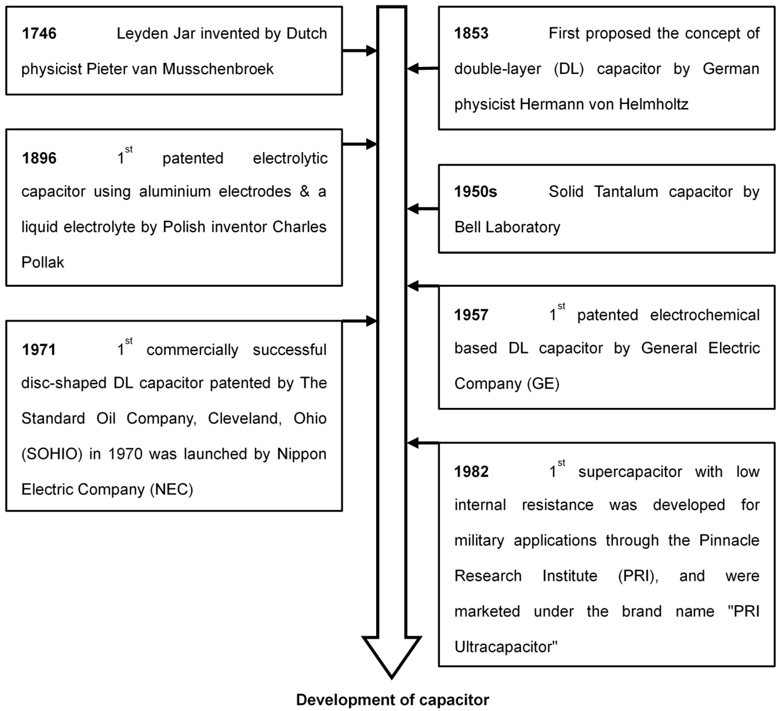
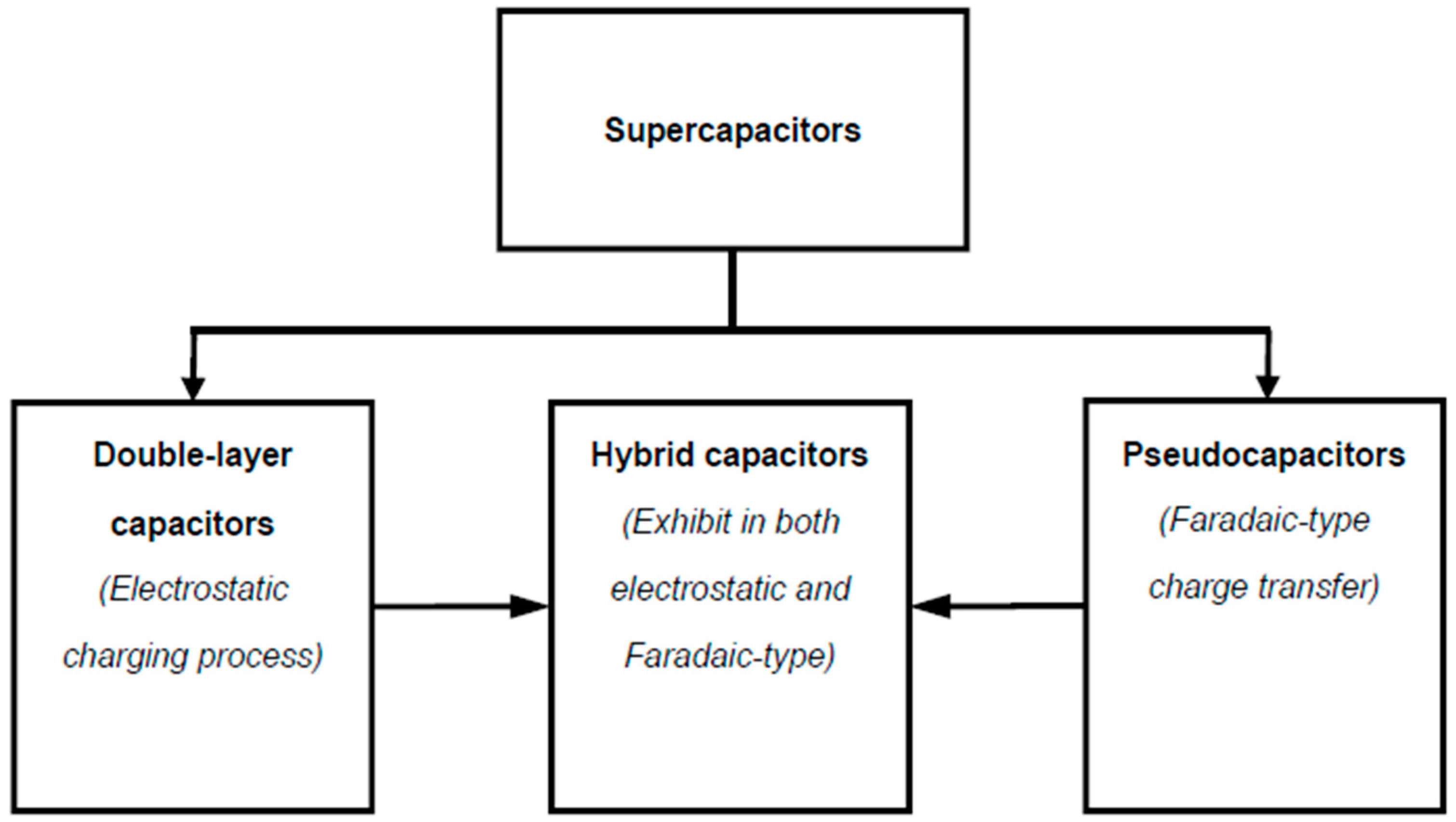
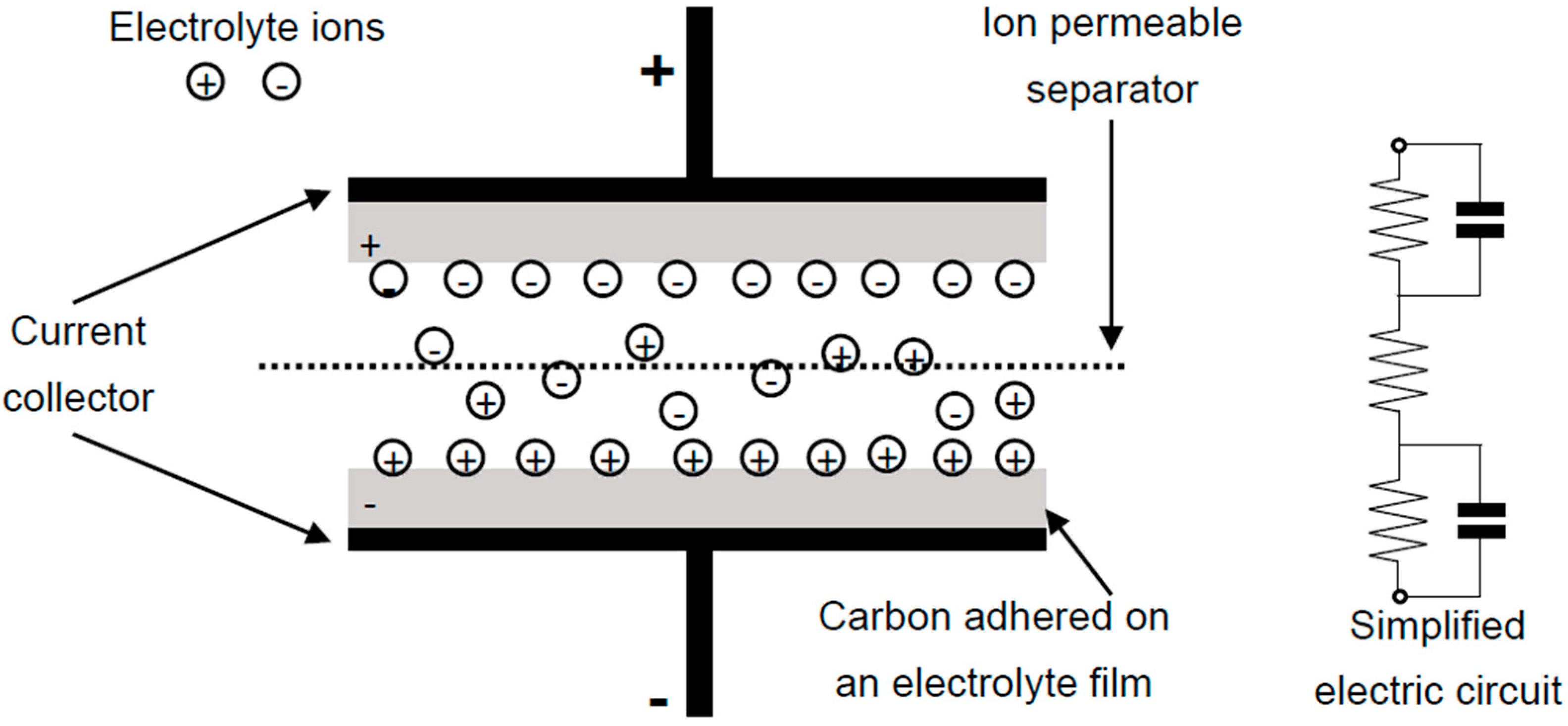
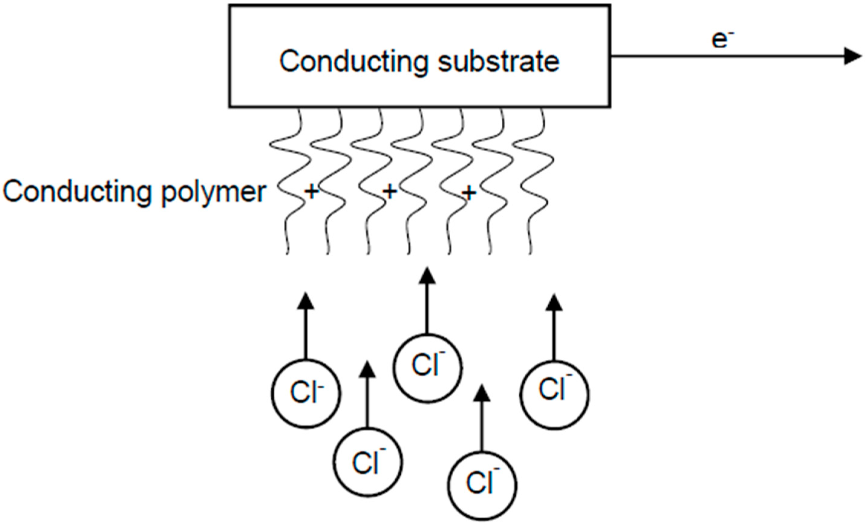
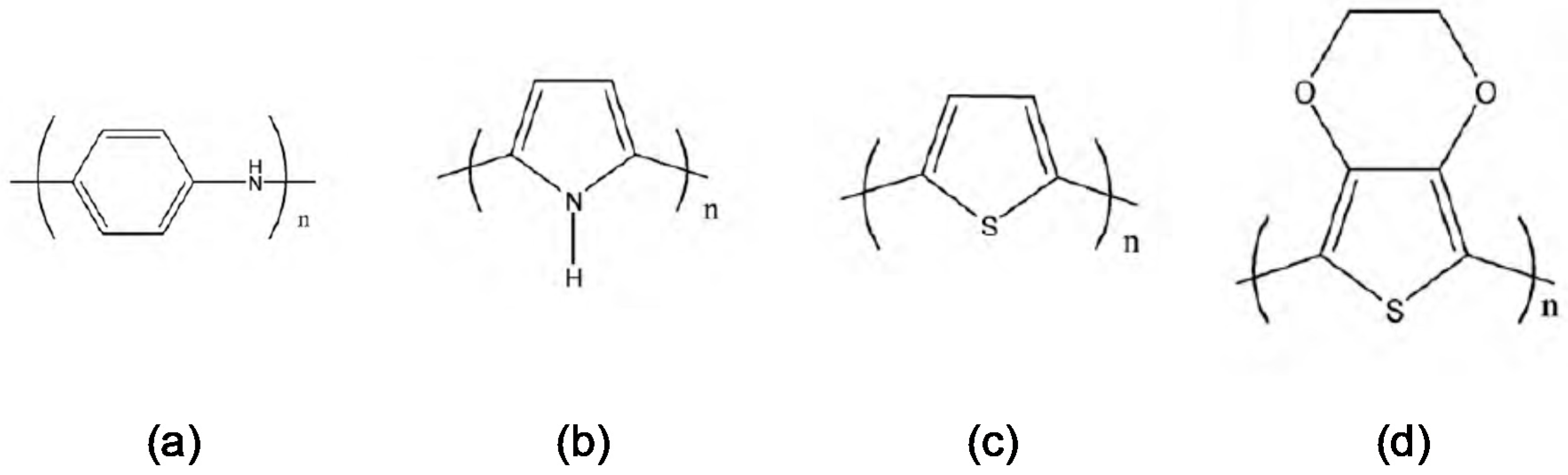
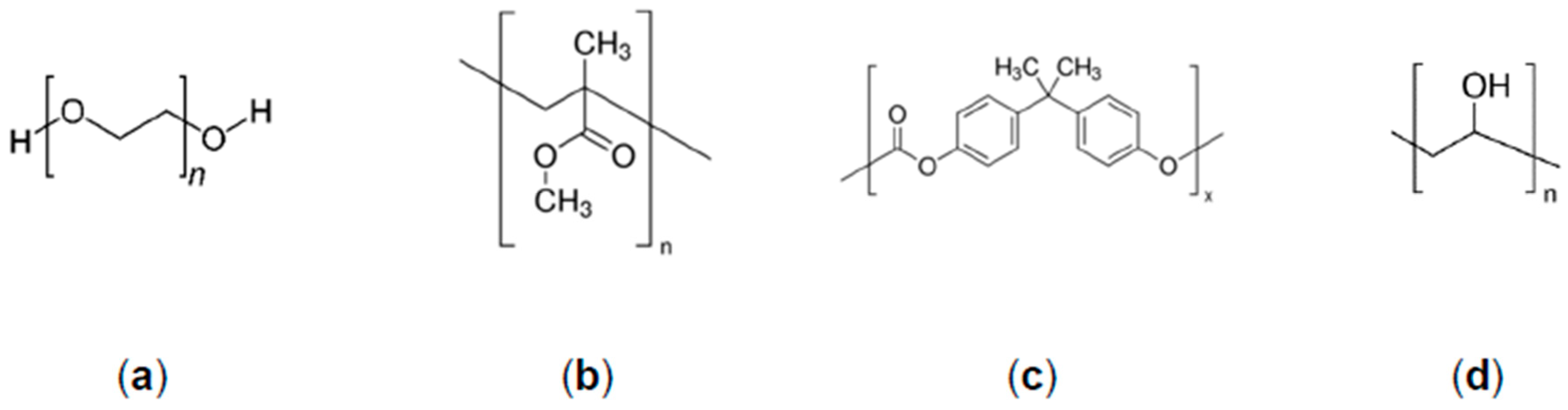
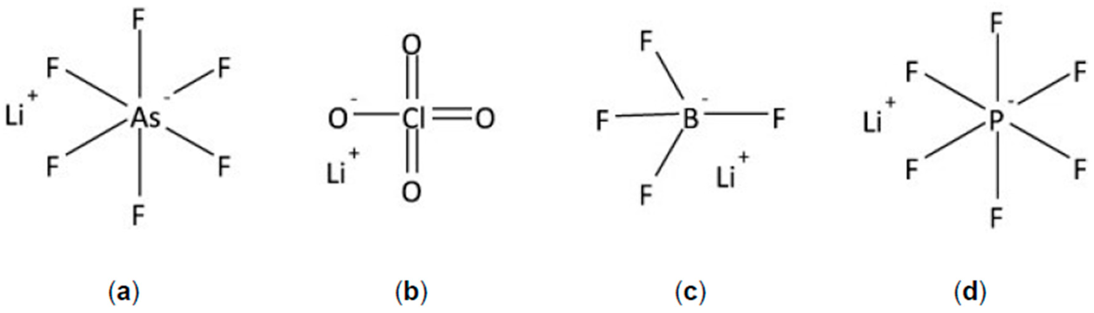
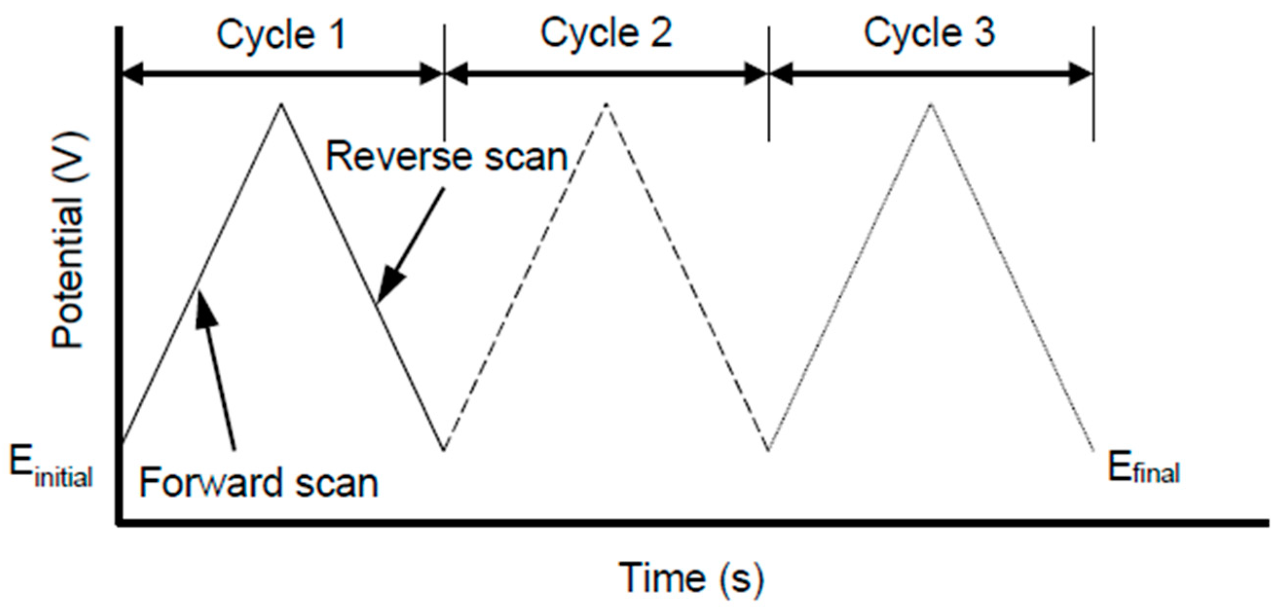
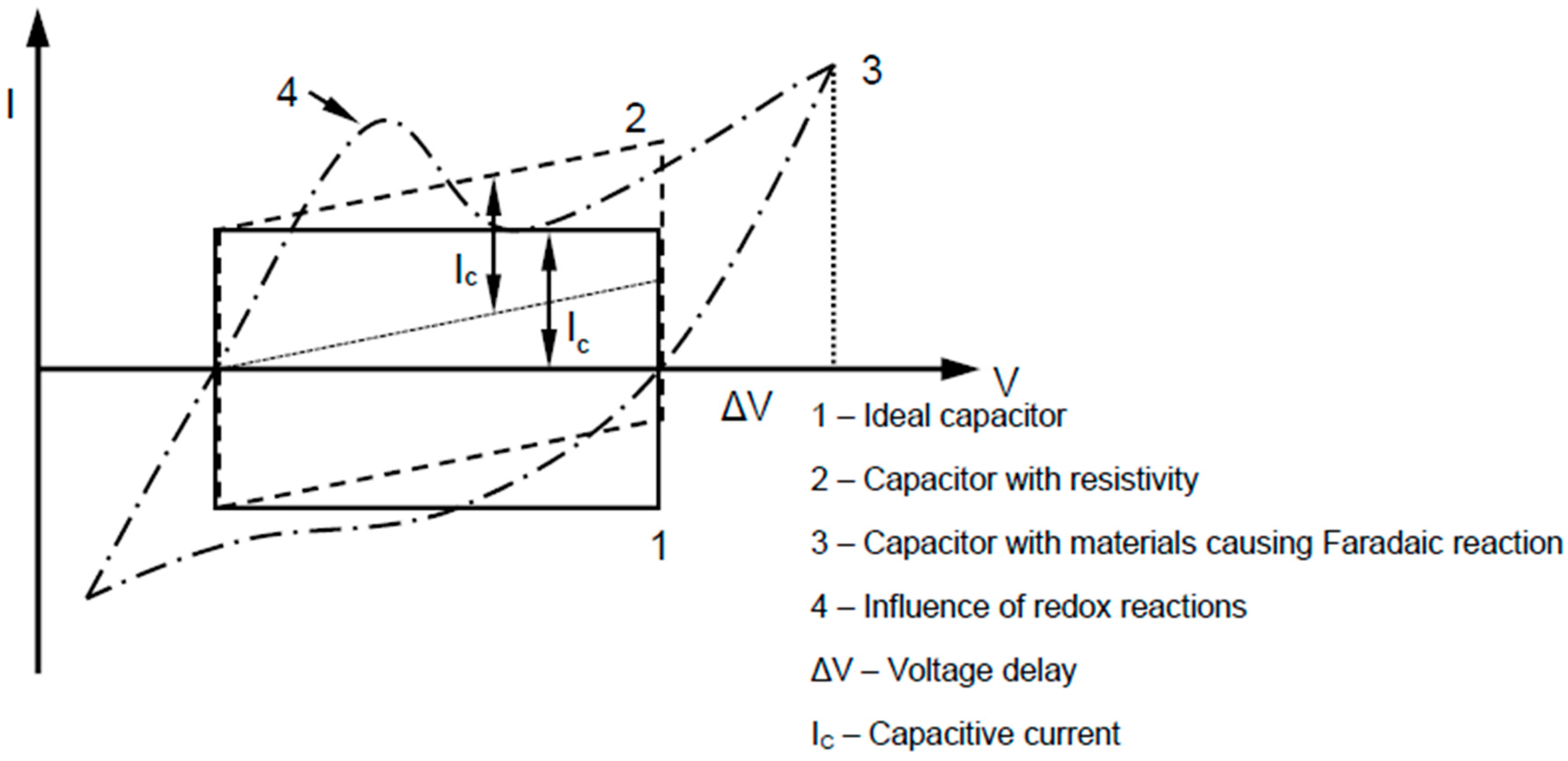
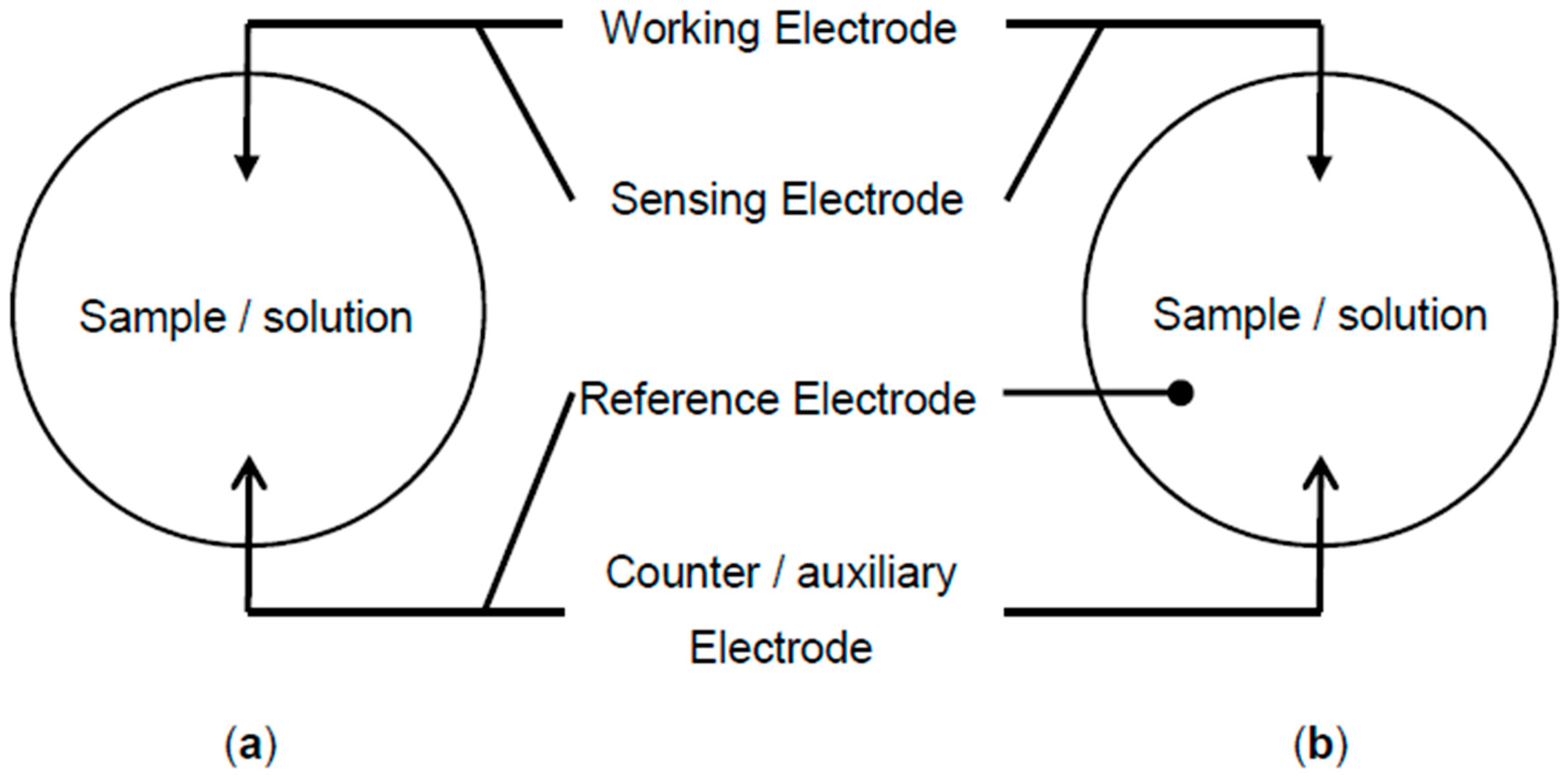
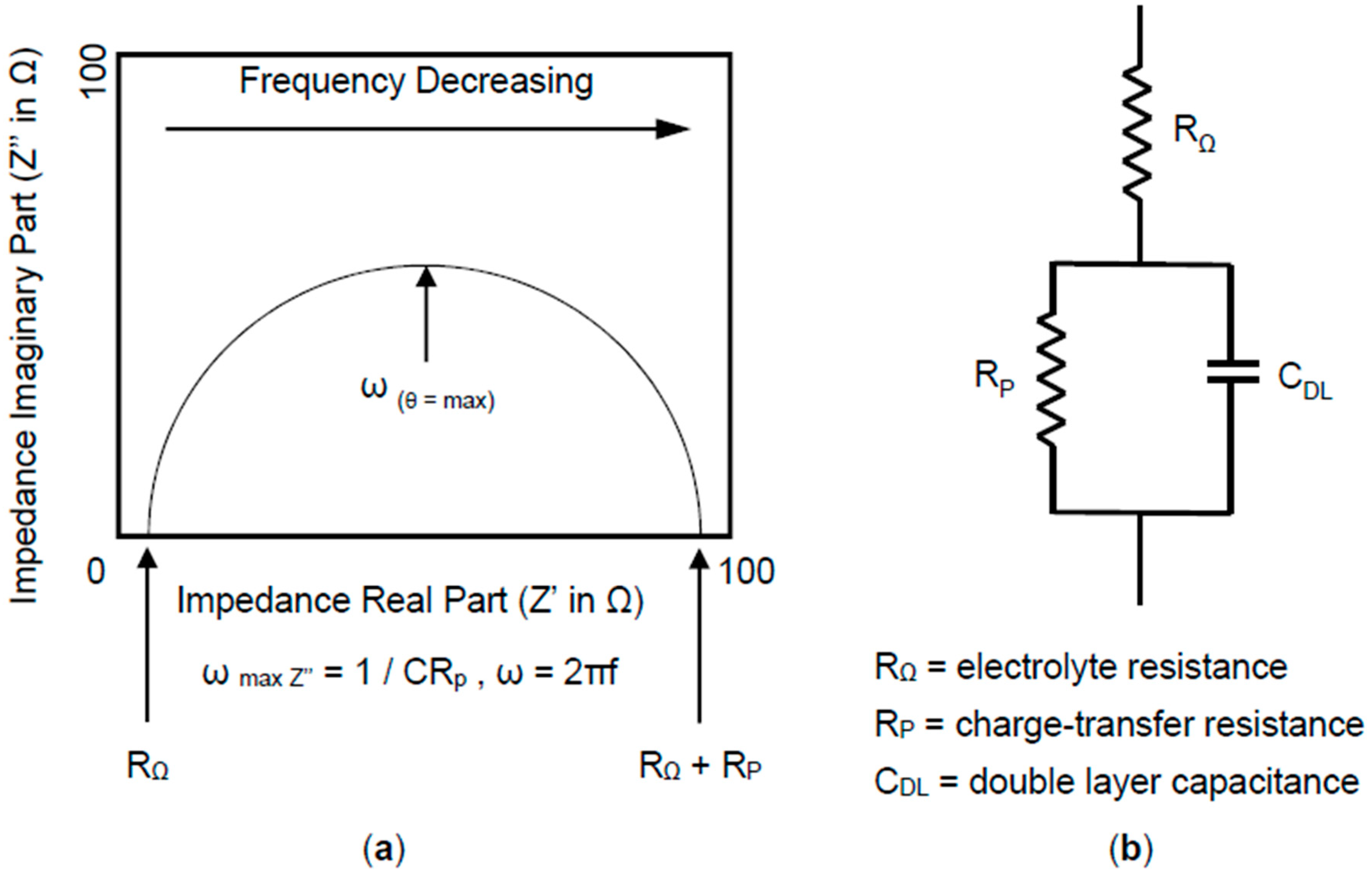
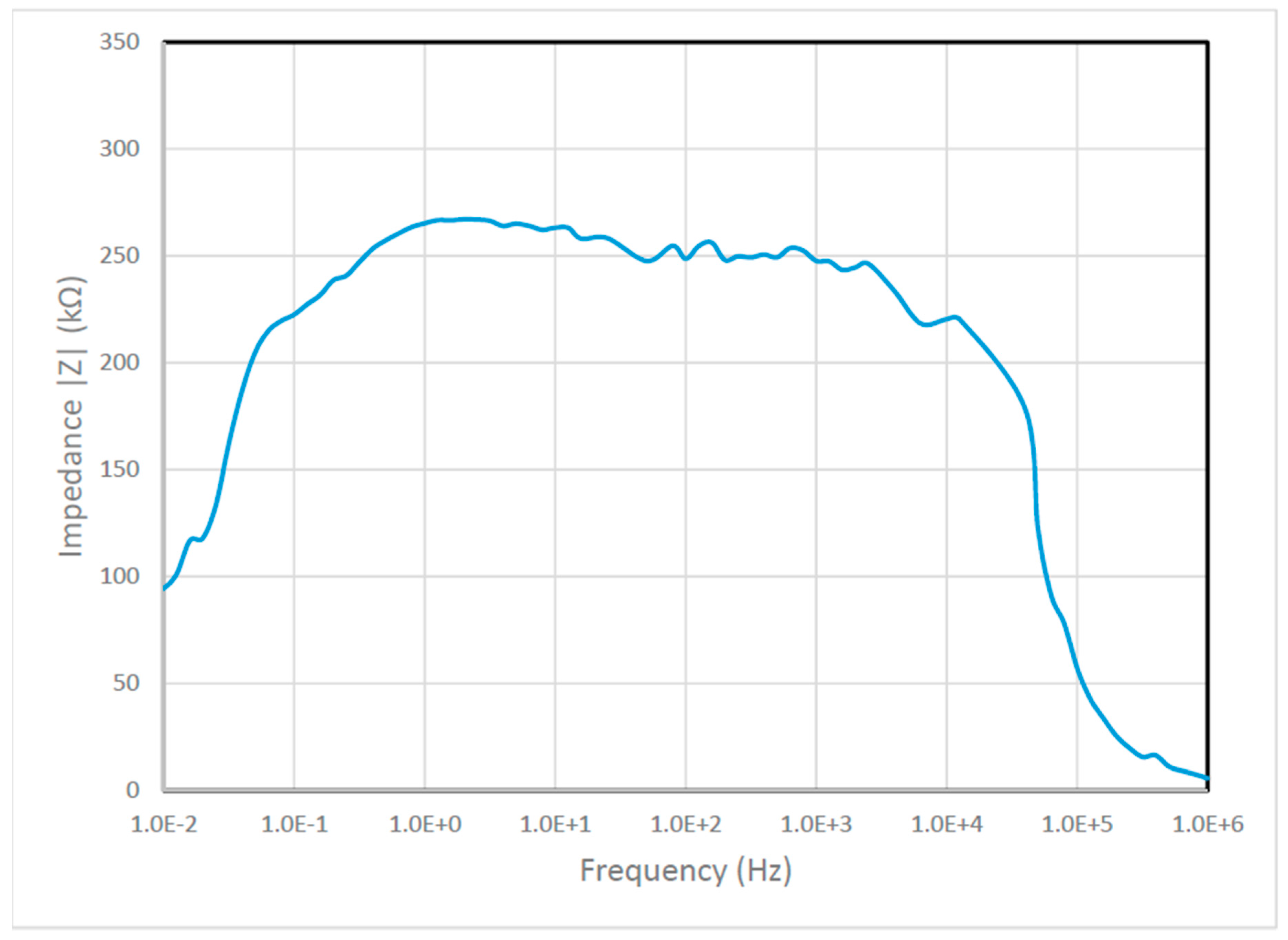
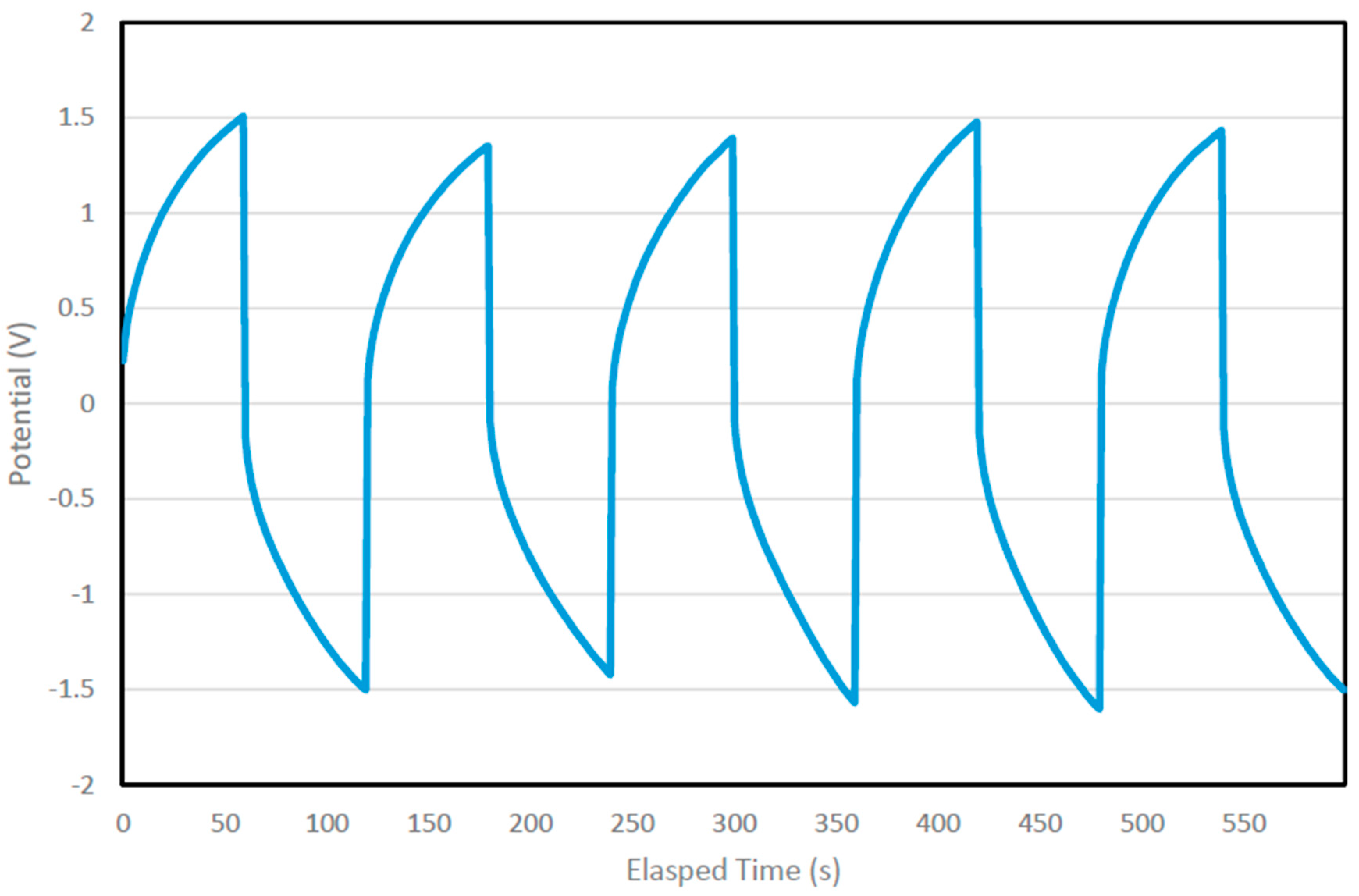
Table 1.
Comparison of typical capacitor and battery characteristics [12].
Table 1.
Comparison of typical capacitor and battery characteristics [12].
| Characteristics | Electrolytic Capacitor | Carbon Supercapacitor | Battery |
|---|---|---|---|
| Specific energy (Wh kg−1) | <0.1 | 1–10 | 10–100 |
| Specific Power (W kg−1) | >>10,000 | 500–10,000 | <1000 |
| Discharging time | 10–6 to 10–3 s | s to min | 0.3–3 h |
| Charging time | 10–6 to 10–3 s | s to min | 1–5 h |
| Charge/discharge efficiency (%) | ~100 | 85–98 | 70–85 |
| Cycle-life (cycles) | Infinite | >500,000 | ~1000 |
| Max voltage (Vmax) determinants | Dielectric thickness and strength | Electrode and electrolyte stability window | Thermodynamics of phase reactions |
| Charge stored determinants | Electrode area and dielectric | Electrode microstructure and electrolyte | Active mass and thermodynamics |
Note: Reproduced with permission from [12], Elsevier, 2019.
© 2019 by the authors. Licensee MDPI, Basel, Switzerland. This article is an open access article distributed under the terms and conditions of the Creative Commons Attribution (CC BY) license (http://creativecommons.org/licenses/by/4.0/).
Share and Cite
MDPI and ACS Style
Hui, C.-y.; Kan, C.-w.; Mak, C.-l.; Chau, K.-h. Flexible Energy Storage System—An Introductory Review of Textile-Based Flexible Supercapacitors. Processes 2019, 7, 922. https://0-doi-org.brum.beds.ac.uk/10.3390/pr7120922
AMA Style
Hui C-y, Kan C-w, Mak C-l, Chau K-h. Flexible Energy Storage System—An Introductory Review of Textile-Based Flexible Supercapacitors. Processes. 2019; 7(12):922. https://0-doi-org.brum.beds.ac.uk/10.3390/pr7120922
Chicago/Turabian StyleHui, Chi-yuen, Chi-wai Kan, Chee-leung Mak, and Kam-hong Chau. 2019. "Flexible Energy Storage System—An Introductory Review of Textile-Based Flexible Supercapacitors" Processes 7, no. 12: 922. https://0-doi-org.brum.beds.ac.uk/10.3390/pr7120922
Note that from the first issue of 2016, this journal uses article numbers instead of page numbers. See further details here.