Article

Interception Characteristics and Pollution Mechanism of the Filter Medium in Polymer-Flooding Produced Water Filtration Process

Petroleum Exploration and Production Research Institute, SINOPEC, Beijing 100083, China
*
Author to whom correspondence should be addressed.
Submission received: 16 October 2019 / Revised: 27 November 2019 / Accepted: 29 November 2019 / Published: 5 December 2019
(This article belongs to the Special Issue Recycling of Waste Oils: Technology and Application)

Abstract

:
Polymer flooding enhances oil recovery, but during the application of this technology, it also creates a large amount of polymer-contained produced water that poses a threat to the environment. The current processing is mainly focused on being able to meet the re-injection requirements. However, many processes face the challenges of purifying effect, facilities pollution, and economical justification in the field practice. In the present work, to fully understand the structure and principle of the oil field filter tank, and based on geometric similarity and similar flow, a set of self-designed filtration simulation devices is used to study the treatment of polymer-contained produced water in order to facilitate the satisfaction of the water injection requirements for medium- and low-permeability reservoirs. The results show that, due to the existence of polymers in oil field produced water, a stable colloidal system is formed on the surface of the filter medium, which reduces the adsorption of oil droplets and suspended solids by the filter medium. The existence of the polymers also increases the viscosity of water, promotes the emulsification of oil pollution, and increases the difficulty of filtration and separation. As filtration progresses, the adsorption of the polymers by the filter medium bed reaches saturation, and the polymers and oil pollution contents in the filtered water increase gradually. The concentration and particle size of the suspended solids eventually exceed the permissible standards for filtered water quality; this is mainly due to the unreasonable size of the particle in relation to the filter medium gradation and the competitive adsorption between the polymers and the suspended solids on the surface of the filter medium. The oil concentration of the filtered water also exceeds the allowable standards and results from the polymers replace the oil droplets in the pores and on the surfaces of the filter medium. Moreover, the suspended particles of the biomass, composed of dead bacteria, hyphae, and spores, have strong attachment and carrying ability with respect to oil droplets, which cause the suspended solids in the filtered water to exceed the permissible standards and oil droplets to be retained in the filtered effluent at the same time.

1. Introduction

Polymer flooding is the leading technology for tertiary oil recovery in oil fields. This technology benefits the oil well and increases production. At the same time, however, residual polyacrylamide is a byproduct of this method of oil recovery, and a large amount of polymer-contained produced water is also produced [1,2]. This kind of produced water can be processed to meet the standards of the water quality index for oil content and suspended solids of less than 20 mg/L by undergoing traditional “two-stage” treatment (two-stage sedimentation and one-stage filtration). After treatment, the refined effluent can then be injected back into a high-permeability reservoir to meet the needs of oil field development and production [3,4,5,6]. However, the current trend in the oil industry is to further diversify the development of medium- and low-permeability reservoirs on the basis of high-permeability reservoir development. With the rise of comprehensive water cuts in oil fields and the application of polymer flooding industrialization, the scale of polymer-contained produced water is increasing [7]. Taking Daqing Oilfield as an example, 9 × 10⁷ t of polymer-flooding produced water is produced every year under the current output [8]. It may appear that the scale of water source is enough to deal with the problem of valuable clear water resources and shortage of deep produced water source in oil field; however, the polymer-flooding produced water has the characteristics of high polymer concentration and suspended solids content. The polymer concentration is between 10 and 1000 mg/L, and the suspended solids content can reach up to 300 mg/L. In order to meet the re-injection requirements of treated produced water, the treatment is required to meet the standards. However, the presence of polymers in the polymer-flooding produced water increases the degree of emulsification, posing a challenge to the entire produced water treatment process. Furthermore, the advanced treatment technology of polymer-contained produced water is not yet mature, which still leads to the problem of water imbalance in the whole oil fields. In other words, there is a gap between the water injection demand and the supply of water with respect to medium- and low-permeability reservoirs, but there is an excess of accumulated polymer-contained produced water in oil field ground systems. In addition, the typical characteristics of polymer-flooding produced water are high electronegativity, high viscosity, small particle size of oil droplets, high strength of water film, and strong emulsification tendency and stability [9,10,11,12]. Many problems arise during the process of treating polymer-flooding produced water, such as the purification effect, facility pollution, running stability, and economic rationality. Moreover, with the increase of polymer concentration, the complexity of the water quality characteristics makes these problems more prominent. In recent years, some innovative technologies for the treatment of polymer-flooding produced water, such as oxidation technology (chlorine dioxide), membrane filtration, biochemical treatment, biofilm, magnetic separation, air flotation, and suspended sludge have attracted attention and attempts.
However, due to investment, operation, and reconstruction, more practical situations are based on the existing two-stage process, making produced water filtration technology of oil field transition from stereotyping to serialization and individualization [13,14,15,16]. First, in reservoirs with different permeability, the targeted treatment of produced water with different water quality has been implemented, and attempts have been made to improve the utilization rate and operating load of the existing equipment. Second, in order to reduce the treatment load of filter tanks, gas flotation deoiling, swirl deoiling, and coarse granulation deoiling have been added to the settling section [17,18,19,20,21,22,23,24,25]. Third, when the purification effect of the filter tank is weakened, the intensity of backwashing is increased by experience, the scour of water flow on the surface of the filter medium is strengthened, and the intensity of rolling and friction of the filter medium is enhanced in order to improve the effect of backwashing and restore the filtration performance of the filter medium [26,27,28]. However, several problems, such as blockage, holding pressure, and large head loss, which are prone to occur during the operation of the filter tank and are caused by the change in water quality when produced water contains polymers, still need to be solved urgently [29,30].
The optimization of an oil–gas production system is important for system efficiency improvement, and the valuable layout optimization methodologies of large-scale oil–gas gathering system were proposed by Liu et al. [31]. In the optimization and design of produced water treatment system, the transportation and attachment of oil droplets and suspended solids to the filter medium constitutes the main process of filtration treatment, and it is also the core process for realizing the advanced treatment of produced water [32,33,34,35,36,37]. The current filtration process and operation parameters of oil fields are constructed and designed for water-drive produced water. In the treatment of polymer-flooding produced water, improper operation parameters will directly affect the water quality, the anti-pollution capabilities of the filtration equipment, and the operational stability of the system. In the final stage of produced water treatment, the effect of oil and suspended solids removal by the filter tank directly affects the quality of water injection [38]. Therefore, the primary research priorities are to study the composition of the pollutants intercepted by the filter medium from polymer-flooding produced water, to analyze the influence of the presence of polymers on oil and suspended solids removal, and to determine why the filtered water quality is not meeting standards. This is the basis of our research on the optimization of water quality, equipment, and operation parameters in the treatment of polymer-flooding produced water. This research will be useful to improve the operation of produced water treatment systems in oil fields that utilize polymer-flooding.

2. Materials and Methods

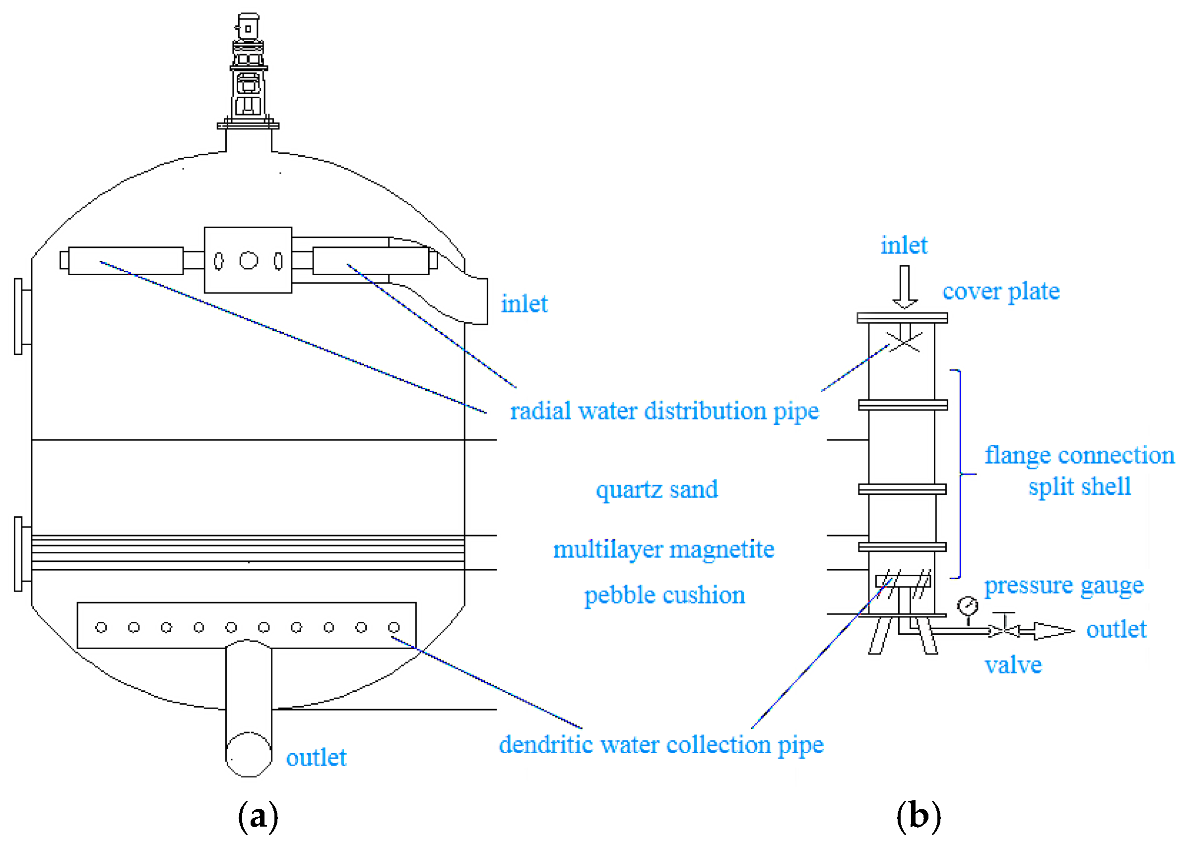
2.1. Design of the Filter Simulation Device

In order to deeply analyze the oil pollution characteristics of the filter layer and study the causes and mechanisms of filter medium pollution, it is necessary to analyze the structure, principle, and technology of the filter tank used in an oil field produced water station. According to this, we designed and built the filtration simulation device, and conducted a laboratory experiment on polymer-flooding produced water filtration.
In the oilfield produced water treatment process, the commonly used filter tank structure is shown in Figure 1a. The produced water separated by the gravity sedimentation of the upper stage flows into the radial water distribution pipe from the inlet, thereby performing uniform water distribution, and flow passes through the grading filter layer to achieve the purpose of removing oil droplets and removing suspended solids. The key to the effectiveness of the filtration process is the gradation form of the filter layer. Then the purified water exits the filter tank from the dendritic water collection pipe. The support layer near the water collection pipe is filled with large-sized pebbles. At the same time, the function of supporting the water collection pipe structure and the uniform water collection in porous medium space is realized; this creates a good flow field for the filtration process.
In order to simulate the filtration process of the polymer-flooding produced water realistically, and analyze interception characteristics of the filter layer and the pollution mechanism of the filter medium, it is necessary to consider that the filter tank has uniform water distribution, uniform water collection, and the gradation form of the filter layer is consistent. This ensures that the designed filtering simulation device and the filter tank in the oil field produced water station are geometrically similar and flow similar.
As shown in Figure 1, the filter tank in the oil field produced water treatment station has a diameter of 4000 mm and a total height of 4500 mm. For geometric similarity, the filter layer, which actually plays a filtration role, is mainly considered. The designed filtration simulation device diameter is 1/10 of the diameter of the oil field filter tank, and the height and grading form of the filter layer are consistent with the filter tank in the oil field. The filter medium ratio filling in the filter layer (in order from top to bottom) is shown in Table 1.
For flow similarity, analyze and consider according to Equation (1).
v = Q/A
where, v—filtering velocity;
Q—incoming water quantity;
A—effective filtration cross section area.
On the basis of filter medium proportioning and gradation consistency, by using the same filtering velocity as the flow similarity criterion, it can ensure that the flow state in the filtration simulation device and the oil field filter tank is the same.
In the design of the device, the problems of pressure bearing, uniform water distribution, uniform water collection, and boundary layer influence are considered respectively. The device is made of plexiglass material, the diameter of the radial water distribution pipe is 20 mm, and the diameter of the dendritic water collection pipe is 10 mm. The split shell is connected by a flange, the thickness is 10 mm, the total height is 2000 mm, the diameter is 400 mm, and the cover plate above the shell is made of phenolic resin.
Compared with the actual filter tank in an oil field, the diameter of the filtration simulation device was only 1/10 of the size, so there must have been a boundary layer with a fast flow velocity near the tank wall. In order to eliminate the influence of the boundary layer on the filtration simulation, the 5 mm area close to the inner wall was compacted when the filter medium was filled. On the inner wall of the device, a strip with a thickness of 3 mm was affixed to the inner wall every 200 mm of the device to block the flow of the boundary layer. In addition, the gasket at the flange joint protruded inward by about 3 mm, further blocking the flow of the boundary layer. The designed pressure resistance of the filter tank in the polymer-flooding produced water station was 0.8 MPa, the maximum pressure was 0.7 MPa in actual operation, and the common pressure was 0.65 MPa. The consistency of the filtration pressure difference was mainly considered in the establishment of the simulation device. Figure 2 shows the filtering simulation device.

2.2. Experimental Water Quality

A water sample at the inlet of the filter tank of the oil field produced water station was used for the laboratory experiment. The raw water contained a polymer concentration of 514 mg/L, the oil content was 79.1 mg/L, and the suspended solids content was 53.7 mg/L. Among them, oil content and suspended solids content were analyzed by means of the spectrophotometry method and the gravimetric method, respectively [39,40], and polymer concentration was analyzed by means of the starch/cadmium iodide method [41]. The water sample was stored in the mixing tank to ensure the uniform dispersion of oil and water. The filtration period was 24 h, and the flow rate of the pump was adjusted to ensure that the Reynolds number of the laboratory device was similar to that of the field device.

3. Results and Discussion

3.1. Analysis of the Pollution Characteristics of the Filter Medium

As shown in Figure 3, after a filtration cycle, the appearance of the filter medium became black overall, and in particular, a great deal of black-brown oil pollution was intercepted on the surface of the filter layer.
The intercepted oil pollution was tested and analyzed by SY/T 5119-2016 “Analysis of soluble organic compounds and crude oil components in rocks”, GB/T 8929-2006 “Determination of water content in crude oil by distillation”, SY/T 0600-2016 “Oil field water scaling trend prediction”, and other related standards. The results are shown in Table 2.
From the analysis of the oil pollution composition, as shown in Table 2, it can be seen that waste oil was the main component of the oil pollution intercepted by the filter medium, accounting for 71%, whereas the solid phase content constituted only 2.35%. Components of colloid and asphaltene were present in the waste oil, accounting for nearly 30%. Thus, the carrying capacity of the polymer-flooding produced water with respect to waste oil was very strong and the difficulty of treating the produced water in this first stage settlement treatment was greatly increased.
Table 3 shows the solid phase composition in the oil pollution, combined with the microscopic morphology as shown in Figure 4, it can be seen that the intercepted oil pollution on the surface of the filter medium was a whole formed by the accumulation and cementitious formation of fine particles. The main elements in the solid phase inorganic composition were Si, O, C, Fe, Al, and Ca, containing 69.69% aluminosilicate (silica, alumina), 12.05% carbonate (calcium carbonate, magnesium carbonate, barium carbonate, etc.), and 9.09% iron oxide. The results show that the components intercepted by the filter layer were crude oil and silicon aluminate scale carried in the process of oil field production, as well as iron oxides formed by the corrosion of pipelines and equipment during transportation.

3.2. The Micromorphology of the Polymers in the Filtration Process

3.2.1. Polymer Concentration Analysis

The polymer concentration in the unfiltered produced water, filtered water, and filter medium after one filtration cycle was analyzed using a starch cadmium iodide method. The results are shown in Table 4.
The analysis shows that there was a significant difference between the polymer concentration in the unfiltered produced water and the filtered water, and the polymer concentration increased from 514 mg/L in the unfiltered produced water to 907 mg/L in the filter medium. Since polymers are not easily dissolved into the filter medium solid and are easily adsorbed on the surface of the filter medium, the polymer concentration adsorbed on the surface of the filter medium is much higher than that of the produced water, which indicates that the filter medium surface can adsorb some of the polymer concentration from the produced water. At the five moments of sampling, the polymer concentration after filtration was lower than that in the unfiltered produced water, which indicates that the filter medium had an adsorption effect on the polymers. However, it can also be observed that the polymer concentration in the water samples after 4 h of filtration was only 22 mg/L, indicating that the filter medium was very effective in the early stage of filtration and the adsorption capacity was the best at this time. With the gradual prolongation of filtration time, the polymers adsorbed on the surface of the filter medium reached saturation, so the polymer concentration in the filtered water increased gradually. As these polymer molecules began to flow out of the filter tank, the small particle size oil droplets and suspended solids also lost the opportunity to contact the surface of the filter medium and were carried out of the tank with the water flow.

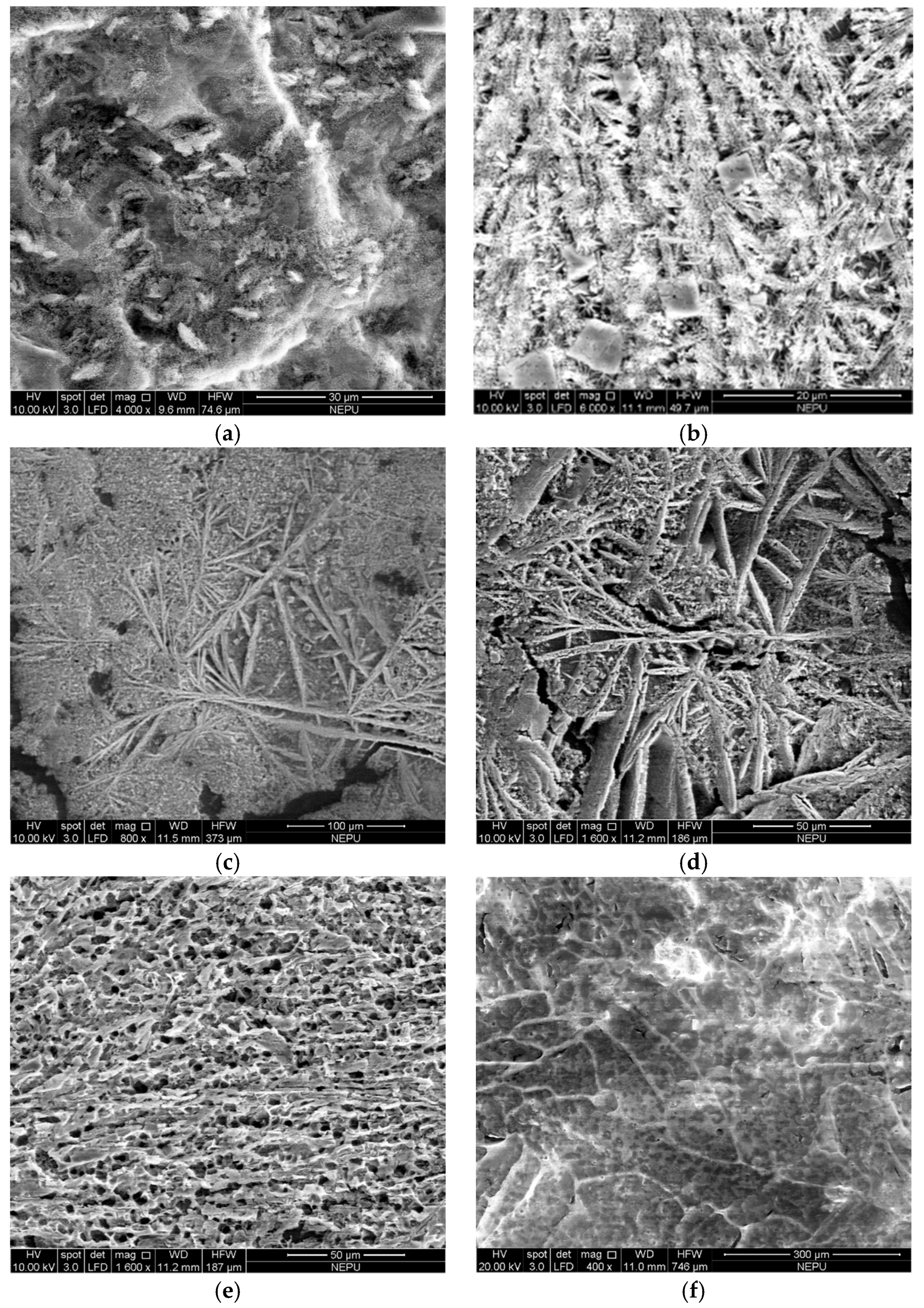
3.2.2. Morphology and Distribution of Residual Polymers Before and After Filtration

The filtration simulation experiment was carried out by using the filtration simulation device, and sampling analysis was performed every 4 h. From the appearance characteristics of the water samples before and after filtration in Figure 5, it can be seen that the produced water before filtration was turbid, and in it, there were many suspended solids and emulsified oil droplets. After filtering for 4 h, the filter medium was relatively clean, because it was in the early stage of filtration; therefore, the interception and adsorption effect of the filter medium on the oil droplets and suspended solids was very high, and the filtered water was also very clear. As the filtration continued, the filter medium intercepted too many oil droplets and suspended solids, polluting the filter medium bed and the filtered effluent, and the adsorption and interception capacity were weakened. Therefore, the color of the water samples from 8 to 20 h after filtration gradually darkened in appearance. Thus, the filtration effect of the filter medium on the unfiltered produced water was obvious, but with the prolongation of filtration time, secondary pollution emerged, and the effectiveness of the treatment worsened.
Figure 6 shows the SEM image of the polymer-flooding produced water tested by freeze-drying before and after filtration. It can be seen that the morphology of the linear polymer molecules in the produced water before filtration was vague and difficult to distinguish and identify; the polymers linear molecules appeared as a blurred white streak. The appearance of this morphological characteristic is due to the high salinity of the produced water, which caused the dried polymers to adsorb a large amount of inorganic salt, and thus, the morphology of the polymer molecules was obscured by the inorganic salt. In the initial stage of filtration, after 4~12 h of filtration, most of the polymers in the produced water were adsorbed and intercepted by the filter medium bed; therefore, the water samples freeze-drying at the outlet after filtration were mainly composed of inorganic minerals, and the crystal structure became very clear. Moreover, polymer linear molecules could not be observed. It was revealed that the polymer molecules with large viscosity attached easily to the surface of the filter medium. However, with the prolongation of the filtration time, after 16–20 h of filtration, the adsorption of the polymers in the filter medium bed gradually reached saturation, and the polymer concentration in the filtered water gradually increased. The polymers adsorbed on the surface and filled in the mineral crystal, making the crystal morphology gradually appear blurry. At the same time, the linear network of polymer molecules gradually appeared.

3.2.3. Microcosmic Characteristics of Intercepted Polymers in the Filter Layer

In the simulation experiment, when filtration was carried out for 23 h, the pressure difference increased to 0.007 MPa, and the effluent flow rate became smaller, indicating that the surface interception and internal absorption of the filter medium bed were saturated, which was regarded as the completion of a filtration cycle. At this point, the filtration simulation ended, the top cover of the filter tank was opened, the layered sampling of quartz sand filter medium (upper, middle, and lower) was carried out, and the surface micromorphology of the wet filter medium was analyzed.
As shown in Figure 7, it can be seen from the microscopic morphology of the polymers on the wet filter medium that the polymers were enriched due to their adsorption on the surface of the filter medium; therefore, the surface of the filter medium particles was coated with thick polymers. This promoted the decrease of the adsorption performance of the filter medium, affected the adsorption of the filter medium with respect to the emulsified oil droplets and suspended solids, and reduced the filtration effect and the filtration efficiency. Moreover, the adsorption of the polymers was a kind of dynamic adsorption. As the polymer mucous membrane thickened, the water phase continuously washed away the old membrane, and then, a new membrane was formed. When the water phase washed away the polymer mucous membrane, it also carried away some oil droplets and suspended solids attached to it, thus worsening the filtration effect.
Similarly, the surface morphology of the polluted filter medium was analyzed by SEM to describe the fouling characteristics and pollution mechanism of the filter layer. Figure 8 shows the SEM images of the upper, middle, and lower quartz sand filter after filtration.
It can be seen that in the upper layer, after the polymer-flooding produced water flowed through the surface of the filter medium, there were flocs on the surface of the angled quartz sand filter medium, and many types of solid particles were adsorbed. At a larger multiple, the adhesion of the suspended solids particles to the surface of the filter medium was more clearly visible, the composition of the suspended solids in the produced water was observed to be complex, and the shape of the suspended solids which adhered to the surface of filter medium was different. In the middle layer, the deposit on the surface of the filter medium was an inorganic/organic complex, and the particles were large, dense, and strong in adhesion. The results show that the long chain of polyacrylamide was broken due to friction and shear when the produced water passed through the filter medium, resulting in the decomposition of the polymers, adhesion to the rough inorganic deposit surface, and formation of an organic deposition layer together with the crude oil in the produced water. In the lower layer, there was a small amount of calcite crystal and flake aragonite on the surface of the filter medium, and no polymer deposition was seen. The results show that with the pore flow of the polymer macromolecules carried by the water phase between the filter medium, the angled quartz sand filter medium pulled off the long chain of polymer molecules, and the polymer molecules changed from long-chain macromolecules to relatively short-chain molecules, which are not easily adhered to the filter medium. Therefore, more of the smaller inorganic deposit crystals were deposited here, and the state was irregular. Under the influence of the flow, the inorganic deposits did not easily form large volume deposits. Although the long chain of polymer molecules became a short chain, it still maintained high polymer concentration, and the longer the filtration time, the higher the polymer concentration in the filtered water. The short-chain and high-concentration polymers still carried oil droplets and suspended solids in the filtered water, which affected the filtration interception and adhesion function.
Figure 9 is the computed tomography scanning diagram of the distribution state of the upper filter medium particles. The blue/blue-purple block area shows the filter medium particles, and the dark pink area shows the suspended solids particles. It can be further seen that there were more suspended solids on the surface of the filter medium, but there were also a lot of suspended solids in the middle of the pores, and no obvious “no suspended solids zone” was formed in the middle of the pores. This indicates that the adsorption of the suspended solids on the surface of the filter medium was a basis, and the suspended solids adhered to each other, connected with each other, and finally filled the pores, which was also the main reason for the blockage of the filter medium and the increasing pressure drop in practical operation.

3.3. Analysis on the Causes of Substandard Filtered Water Quality

3.3.1. Analysis on the Causes of Substandard Suspended Solids in the Filtered Water

The failure of the filter medium to intercept and adsorb the suspended solids in the water is the fundamental reason why the filtered water does not meet permissible standards. The water flow carries suspended solids in the channel of the filter medium pores, and the size of the pores has a certain influence on the interception effect. From the point of view of the relative size of the pores and the suspended solids, the reasons for the high amount of suspended solids are analyzed below.
There are two kinds of maximum probability of filter medium particle stacking: triangular stacking and square stacking. In this study, the pore inscribed circle method was used to calculate the minimum diameter of the pores formed by these two stacking methods, as shown in Table 5.
(1) Triangular Stacking
As shown in Figure 10, according to the geometric relationship of the inscribed circles in the pores, the radius of the inscribed circle is r = 2 3 3 R R ; therefore, the pore diameter is d = 2r = 0.3094 R. If the particle diameter is set to D, then R = D/2; therefore, the pore diameter is d = 0.1547 D.
(2) Square Stacking
As shown in Figure 11, an inscribed circle is made inside the pore, and the diameter of the inscribed circle is taken as the pore diameter. According to the geometric relationship, the diameter of the inscribed circle is as follows: d = ( 2 − 1) D = 0.414 D.
The interception effect of the filter medium on the suspended solids can be divided into screening and adsorption. The screening effect is aimed at the larger suspended solids particles, which can be intercepted on the surface of the filter layer, because they cannot pass through the filter layer. Although the smaller suspended solids particles can enter the filter layer, these particles are adsorbed in the filter layer and filtered out, which is the adsorption effect.
Under this kind of filter medium gradation form, the particle size of the quartz sand filter medium was 0.8 mm, and the pore diameters of the triangular and square stacking modes were 123.76 and 331.2 μm, respectively. According to the 1/3 bridge principle, the minimum diameter of the suspended solids that could be intercepted by these two stacking methods was 41.25 and 110.4 μm, respectively. There was a magnetite layer with a smaller particle size in the filter medium gradation. According to the minimum particle size of 0.25 mm, the pore diameters of the triangle and square stacking modes were 38.675 and 103.5 μm, respectively. According to the 1/3 bridge principle, the minimum diameter of suspended solids that could be intercepted by these two stacking methods was 12.9 and 34.5 μm, respectively.
As shown in Table 5, according to the standard SY/T 5329-2012 “Recommended index and analysis method for water injection quality of a clastic rock reservoir”, the requirement for the median particle size of the suspended solids to maintain water injection quality is 2.0~4.0 μm. If only the bridge interception capacity is relied upon, small enough particles of the suspended solids cannot be removed, and the filtered water cannot meet the standard. Therefore, the effective removal of the suspended solids by the filter medium cannot rely only on the bridge interception capacity of the filter layer but must also rely on the adsorption capacity of the inner surface of the filter layer.
The particle size distribution of the suspended solids in the unfiltered produced water was determined by a laser particle size analyzer. In Figure 12, the results show that the particle size range of the suspended solids in the unfiltered produced water was 1.21~116.80 μm, and the median particle size was 19.93 μm. In Figure 13, it can be seen that the particle size range of the suspended solids in the filtered water was 0.43~62.63 μm, and the median particle size was 10.06 μm.
Between the two kinds of filter packing methods—triangle and square the pores formed by square stacking were larger (34.5 μm), indicating that the theoretical minimum suspended solids removal rate was 33.63%. However, the maximum particle size of the suspended solids in the filtered water was 50.88 μm, indicating that suspended solids particles larger than this particle size were filtered out and the actual removal rate was 14.72%. The filter medium not only removed the suspended solids by interception, but the small particles were also adsorbed by the filter medium in the filter layer. The removal rate should have been greater than 33.63% but was actually only 14.72%, indicating that there were many adverse effects on the removal of the suspended solids under the conditions of polymerization.
According to the data and analysis, the reasons that the content and particle size of the suspended solids in the filtered water exceeded the standard can be summarized as follows: (1) The porosity of the filter layer was large, only 20%~30% of particles of sufficient size can be intercepted by the bridge principle, and other particles that are smaller than the pores must rely on the adsorption of the filter medium surface in order to be intercepted. (2) There is competitive adsorption between the polymers and the suspended solids on the surface of the filter medium, and the affinity of the filter medium surface to the polymers is greater than that to the suspended solids, which limits the adsorption capacity on the surface of the filter medium with respect to the suspended solids.

3.3.2. Analysis on the Causes of Substandard Oil Content in the Filtered Water

1. Effect of the polymers
The relative positions of the oil droplets and the residual polymers between the filter medium were analyzed to investigate the accumulation and adhesion of the two in the filter medium. Figure 14 shows the adhesion characteristics of the polymers and oil droplets at different observation points of the filter layer. It can be seen that under ordinary light irradiation, the surface of the filter medium particles was bright, and the oil droplets or oil films were yellow-green under ultraviolet light irradiation.
Obviously, the viscosity of the polymers was larger than that of the oil droplets, and the surface of the filter medium was mostly adhered to by the polymer molecules. Most of the crude oil in the filter layer was distributed in the pores of the filter medium particles in film or droplet form, which leads to the problem of water flow washing away the oil droplets or oil films in the pores. Even if part of the oil droplets adhere to the surface of the filter medium, because the viscosity of the polymer-flooding produced water is relatively larger and because of the replacement effect, the crude oil is easily replaced by the polymers on the surface of the filter medium and in the pores of the filter layer, resulting in the loss of opportunity for the oil droplets to sufficiently adhere to the surface of the filter medium.
2. Effects of the suspended particles of the biomass
The filter membrane was used to filter the polymer-flooding produced water to obtain the oil mud interceptor, which was further washed, and the crude oil, polymers, and inorganic mineralization ions were removed in order to obtain the suspended particles of the biomass.
As shown in Figure 15, according to the results of the scanning electron microscope analysis, there was a large amount of suspended solids with spatial reticular structure in the produced water, and the pores were very developed; they are supposed to be composed of dead bacteria, hyphae, and spores. Its chemical components were cellulose and lignin, which have strong adsorption capacity for crude oil, polymers, and mud. During the filtration process, these oils were carried into the filtered water by the suspended particles of the biomass, which is one of the reasons why the oil content of the filtered water exceeded the permissible standard.

4. Conclusions

(1) Due to the existence of the polymers in the produced water, a stable colloidal system was formed on the surface of the filter medium, which reduced the adsorption of the crude oil and suspended solids by the filter medium. The existence of the polymers also increased the viscosity of the water, promoted the emulsification of the oil pollution, and increased the difficulty of the filtration separation, thus affecting the filtration effect. As a result, the content of the oil and suspended solids in the filtered water was higher than the permissible standard.
(2) As the polymers in the produced water was adsorbed on the surface of the filter medium particles and spread into a thin film, the outline became blurred. In the initial stage of filtration, most of the polymers and oil pollution in the produced water were adsorbed and intercepted by the filter medium bed, and the filtered water mainly contained inorganic mineral ions. At the later stage of filtration, the adsorption of the polymers by the filter medium bed gradually reached saturation, and the polymers and oil pollution content in the filtered water increased gradually.
(3) The concentration and particle size of the suspended solids exceeded the permissible standard after filtration which is mainly due to the unreasonable size and filter medium gradation, and the competitive adsorption mechanism between the polymers and the suspended solids on the surface of the filter medium. However, the oil concentration of the filtered water exceeded the allowable standard, because the polymers have the replacement effect on the oil droplets in the pores and on the surface of the filter medium, and the biomass suspended particles composed of dead bacteria, hyphae, and spores had strong adsorption and carrying ability with respect to the oil droplets, which caused the suspended solids in the filtered water to exceed the standard while the oil droplets were simultaneously retained in the effluent.
(4) In order to improve the filtration efficiency and ensure that the filtered water quality meets the applicable standards, we plan to conduct future studies investigating ways to replace the aging filter medium in a timely manner and take measures to prevent mixing layer and running media between different layers of the filter medium, strengthen the cleaning of the filter medium regularly to ensure efficient filtration performance, and optimize the filter medium gradation to achieve a better overall filtration effect. Furthermore, some new oxidation technologies, such as the oxidation of polymer-flooding produced water with chlorine dioxide, thereby reducing the polymer concentration in produced water and re-modifying the water quality to the conventional treatment process, is a useful research direction of produced water treatment in polymer-flooding technology.

Author Contributions

Conceptualization, writing—original draft, investigation, X.W.; funding acquisition, supervision, X.X.; project administration, formal analysis, W.D.; methodology, Z.T.; writing—review and editing, C.H.; visualization, B.W.

Funding

This research was funded by the National Natural Science Foundation of China, grant number 51508573, 51674086.

Acknowledgments

This research was supported by the National Natural Science Foundation of China (Grant No. 51508573, 51674086).

Conflicts of Interest

The authors declare no conflicts of interest.

References

  1. Li, J.X. Polymer Flooding Ground Engineering Technology; Petroleum Industry Press: Beijing, China, 2008; pp. 1–25. [Google Scholar]
  2. Gao, B.; Jia, Y.; Zhang, Y.; Li, Q.; Yue, Q. Performance of dithiocarbamate-type flocculant in treating simulated polymer flooding produced water. J. Environ. Sci. 2011, 23, 37–43. [Google Scholar] [CrossRef]
  3. Zhang, R.; Yu, S.; Shi, W.; Tian, J.; Zhang, Z. Optimization of membrane cleaning strategy for advanced treatment of polymer flooding produced water by nanofiltration. RSC Adv. 2016, 6, 28844–28853. [Google Scholar] [CrossRef]
  4. Wang, Z.H.; Lin, X.Y.; Yu, T.Y.; Zhou, N.; Zhong, H.Y.; Zhu, J.J. Formation and rupture mechanisms of visco-elastic interfacial films in polymer-stabilized emulsions. J. Dispers. Sci. Technol. 2019, 40, 612–626. [Google Scholar] [CrossRef]
  5. Nie, C.; Xu, L.; Gu, D.; Cao, G.; Yuan, R.; Wang, B. Toward efficient demulsification of produced water in oilfields: Solar step directional degradation of polymer on interfacial film of emulsions. Energy Fuels 2016, 30, 9686–9692. [Google Scholar] [CrossRef]
  6. Zhang, J.; Jing, B.; Tan, G.; Zhai, L.; Fang, S.; Ma, Y. Comparison of performances of different type of clarifiers for the treatment of oily wastewater produced from polymer flooding. Can. J. Chem. Eng. 2015, 93, 1288–1294. [Google Scholar] [CrossRef]
  7. Xia, Q.; Guo, H.; Ye, Y.; Yu, S.; Zhang, R. Study on the fouling mechanism and cleaning method in the treatment of polymer flooding produced water with ion exchange membranes. RSC Adv. 2018, 8, 29947–29957. [Google Scholar] [CrossRef] [Green Version]
  8. Wang, Z.H.; Bai, Y.; Zhang, H.Q.; Liu, Y. Investigation on gelation nucleation kinetics of waxy crude oil emulsions by their thermal behavior. J. Pet. Sci. Eng. 2019, 181, 106230. [Google Scholar] [CrossRef]
  9. Chen, H.X.; Tang, H.M.; Duan, M.; Liu, Y.G.; Liu, M.; Zhao, F. Oil-water separation property of polymer-contained wastewater from polymer-flooding oilfields in Bohai Bay, China. Environ. Technol. 2015, 36, 1373–1380. [Google Scholar] [CrossRef]
  10. Ren, G.M.; Sun, D.Z.; Chunk, J.S. Advanced treatment of oil recovery wastewater from polymer flooding by UV/H_2O_2/O_3 and fine filtration. J. Environ. Sci. 2006, 18, 29–32. [Google Scholar]
  11. Liu, A.; Liu, S.Y. Study on performance of three backwashing modes of filtration media for oilfield wastewater filter. Desalin. Water Treat. 2016, 57, 10498–10505. [Google Scholar] [CrossRef]
  12. Ebrahimi, M.; Kovacs, Z.; Schneider, M.; Mund, P.; Bolduan, P.; Czermak, P. Multistage filtration process for efficient treatment of oil-field produced water using ceramic membranes. Desalin. Water Treat. 2012, 42, 17–23. [Google Scholar] [CrossRef] [Green Version]
  13. Makhmudov, Z.M.; Saidullaev, U.Z.; Khuzhayorov, B.K. Mathematical model of deep-bed filtration of a two-component suspension through a porous medium. Fluid Dyn. 2017, 52, 299–308. [Google Scholar] [CrossRef]
  14. Bai, B.; Wang, J.Q.; Zhai, Z.Q.; Xu, T. The penetration processes of red mud filtrate in a porous medium by seepage. Transp. Porous Media 2017, 117, 207–227. [Google Scholar] [CrossRef]
  15. Sharafutdinov, R.F.; Bochkov, A.S.; Sharipov, A.M.; Sadretdinov, A.A. Filtration of live oil in the presence of phase transitions in a porous medium with inhomogeneous permeability. J. Appl. Mech. Tech. Phys. 2017, 58, 271–274. [Google Scholar] [CrossRef]
  16. Nasre-Dine, A.; Ahmed, H.; Abdellah, A.; Wang, H.Q.; Gilbert, L.B.; Tariq, O. Porous media grain size distribution and hydrodynamic forces effects on transport and deposition of suspended particles. J. Environ. Sci. 2017, 53, 161–172. [Google Scholar]
  17. Le, T.V.; Imai, T.; Higuchi, T.; Yamamoto, K.; Sekine, M.; Doi, R.; Vo, H.T.; Wei, J. Performance of tiny microbubbles enhanced with “normal cyclone bubbles” in separation of fine oil-in-water emulsions. Chem. Eng. Sci. 2013, 94, 1–6. [Google Scholar] [CrossRef]
  18. Xu, H.X.; Liu, J.T.; Wang, Y.T.; Cheng, G.; Deng, X.W.; Li, X.B. Oil removing efficiency in oil–water separation flotation column. Desalin. Water Treat. 2015, 53, 2456–2463. [Google Scholar] [CrossRef]
  19. Li, R.Y. Application of gas-assisted solvent flotation technique on oil-field polymer-bearing produced water. Appl. Mech. Mater. 2013, 316–317, 902–905. [Google Scholar] [CrossRef]
  20. Chiavonefilho, O. Oil removal of oilfield-produced water by induced air flotation using nonionic surfactants. Desalin. Water Treat. 2015, 56, 1802–1808. [Google Scholar]
  21. Bhaskar, K.U.; Murthy, Y.R.; Raju, M.R.; Tiwari, S.; Srivastava, J.K.; Ramakrishnan, N. CFD simulation and experimental validation studies on hydrocyclone. Miner. Eng. 2007, 20, 60–71. [Google Scholar] [CrossRef]
  22. Bai, Z.S.; Wang, H.L.; Tu, S.T. Experimental study of flow patterns in deoiling hydrocyclone. Miner. Eng. 2009, 22, 319–323. [Google Scholar] [CrossRef]
  23. Bergström, J.; Vomhoff, H. Experimental hydrocyclone flow field studies. Sep. Purif. Technol. 2007, 53, 8–20. [Google Scholar] [CrossRef]
  24. Lim, E.W.C.; Chen, Y.R.; Wang, C.H.; Wu, R.M. Experimental and computational studies of multiphase hydrodynamics in a hydrocyclone separator system. Chem. Eng. Sci. 2010, 65, 6415–6424. [Google Scholar] [CrossRef]
  25. Zhang, Y.; Gao, B.; Lu, L.; Yue, Q.; Wang, Q.; Jia, Y. Treatment of produced water from polymer flooding in oil production by the combined method of hydrolysis acidification-dynamic membrane bioreactor–coagulation process. J. Pet. Sci. Eng. 2010, 74, 14–19. [Google Scholar] [CrossRef]
  26. Filtration & Separation Group. New filtration technology reduces backwash wastewater. Filtr. Sep. 2010, 47, 8. [Google Scholar]
  27. Slavik, I.; Jehmlich, A.; Uhl, W. Impact of backwashing procedures on deep bed filtration productivity in drinking water treatment. Water Res. 2013, 47, 6348–6357. [Google Scholar] [CrossRef]
  28. Henderson, A. Backwashing filtration systems. Prod. Finish. 2002, 55, 23. [Google Scholar]
  29. Loderer, C.; Pawelka, D.; Vatier, W.; Hasal, P.; Fuchs, W. Dynamic filtration-Ultrasonic cleaning in a continuous operated filtration process under submerged conditions. Sep. Purif. Technol. 2013, 119, 72–81. [Google Scholar] [CrossRef]
  30. Liu, Q.Y.; Dai, Y.; Luo, Y.; Chen, Y.L. Ultrasonic-intensified chemical cleaning of nano filtration membranes in oilfield sewage purification systems. J. Eng. Fibers Fabr. 2016, 11, 17–25. [Google Scholar] [CrossRef]
  31. Liu, Y.; Chen, S.Q.; Guan, B.; Xu, P. Layout optimization of large-scale oil-gas gathering system based on combined optimization strategy. Neurocomputing 2019, 332, 159–183. [Google Scholar] [CrossRef]
  32. Liu, G.; Zhang, F.; Qu, Y.; Liu, H.; Zhao, L.; Cui, M.; Ou, Y.; Geng, D. Application of PAC and flocculants for improving settling of solid particles in oilfield wastewater with high salinity and Ca2+. Water Sci. Technol. 2017, 76, 1399–1408. [Google Scholar] [CrossRef] [PubMed]
  33. Zhang, Z. The flocculation mechanism and treatment of oily wastewater by flocculation. Water Sci. Technol. 2017, 76, 2630–2637. [Google Scholar] [CrossRef] [PubMed] [Green Version]
  34. Ottaviano, J.G.; Cai, J.X.; Murphy, R.S. Assessing the decontamination efficiency of a three-component flocculating system in the treatment of oilfield-produced water. Water Res. 2014, 52, 122–130. [Google Scholar] [CrossRef] [PubMed]
  35. Guo, J.L.; Meng, J.; Li, G.P.; Luan, Z.K.; Tang, H.X. Physicochemical interaction and its influence on deep bed filtration process. J. Environ. Sci. 2004, 16, 297–301. [Google Scholar]
  36. Wu, C.Y.; Wang, Y.N.; Zhou, Y.X.; Zhu, C. Pretreatment of petrochemical secondary effluent by micro-flocculation and dynasand filtration, performance and DOM removal characteristics. Water Air Soil Pollut. 2016, 227, 415. [Google Scholar] [CrossRef]
  37. Si, S.; Yan, Z.; Gong, Z. Pilot study of oilfield wastewater treatment by micro-flocculation filtration process. Water Sci. Technol. 2018, 77, 101–107. [Google Scholar] [CrossRef]
  38. Zamani, A.; Maini, B. Flow of dispersed particles through porous media-deep bed filtration. J. Pet. Sci. Eng. 2009, 69, 71–88. [Google Scholar] [CrossRef]
  39. Weschenfelder, S.E.; Mello, A.C.C.; Borges, C.P.; Campos, J.C. Oilfield produced water treatment by ceramic membranes: Preliminary process cost estimation. Desalination 2015, 360, 81–86. [Google Scholar] [CrossRef]
  40. Jordan, M.M.; Johnston, C.J.; Robb, M. Evaluation methods for suspended solids and produced water as an aid in determining effectiveness of scale control both downhole and topside. SPE Prod. Oper. 2006, 21, 7–18. [Google Scholar] [CrossRef]
  41. Zhong, H.; Yang, T.; Yin, H.; Lu, J.; Zhang, K.; Fu, C. Role of alkali type in chemical loss and ASP-flooding enhanced oil recovery in sandstone formations. SPE Reserv. Eval. Eng. 2019. [Google Scholar] [CrossRef]
Figure 1. Schematic illustration of the filtration device for treating polymer-flooding produced water: (a) oil field filter tank; (b) filtration simulation device.
Processes 07 00927 g001
Figure 2. Filtration simulation device for treating polymer-flooding produced water: (a) whole shape; (b) top water distribution pipe; (c) bottom water collection pipe.
Processes 07 00927 g002
Figure 3. Intercepted oil pollution on the surface of the filter layer.
Processes 07 00927 g003
Figure 4. Micromorphology of the oil pollution on the filter medium surface (amplification factor: 3000).
Processes 07 00927 g004
Figure 5. Appearance of the polymer-flooding produced water before and after filtration. (a) unfiltered produced water; (b) 4 h; (c) 8 h; (d) 12 h; (e) 16 h; (f) 20 h.
Processes 07 00927 g005
Figure 6. Micromorphology of polymer flooding produced water before and after filtration: (a) before filtration; (b) after filtration for 4 h; (c) after filtration for 8 h; (d) after filtration for 12 h; (e) after filtration for 16 h; (f) after filtration for 20 h. Amplification factor: 3000.
Processes 07 00927 g006
Figure 7. Metallograph of polymers adhered on the wet filter medium.
Processes 07 00927 g007
Figure 8. Micromorphology of quartz sand after filtration: (a) upper filter layer; (b) central filter layer; (c) bottom filter layer. Amplification factor: 6000.
Processes 07 00927 g008
Figure 9. Computed tomography scanning of the oil pollution in the upper filter layer.
Processes 07 00927 g009
Figure 10. Triangle stacking mode.
Processes 07 00927 g010
Figure 11. Square stacking mode.
Processes 07 00927 g011
Figure 12. Particle size distribution of the suspended solids in the unfiltered produced water.
Processes 07 00927 g012
Figure 13. Particle size distribution of the suspended solids in the filtered water.
Processes 07 00927 g013
Figure 14. Micromorphological distribution of the polymer and oil in the filter layer: (a) polymers micromorphology; (b) crude oil micromorphology.
Processes 07 00927 g014
Figure 15. Suspended solids after wash (amplification factor: 400).
Processes 07 00927 g015
Table 1. Filter medium proportioning and gradation.
Number of Filter LayerFilter Medium TypeParticle DiameterThickness
1quartz sandφ0.8 mm800 mm
2magnetiteφ0.25–0.5 mm50 mm
3magnetiteφ1–2 mm50 mm
4magnetiteφ2–4 mm100 mm
5magnetiteφ4–8 mm100 mm
6magnetiteφ8–16 mm100 mm
7pebble cushionφ16–32 mm300 mm (Filtration simulation device)
1300 mm (Oil field filter tank)
Table 2. Oil pollution components.
Sample NameWater Content (%)Waste Oil (%)Solid Content (%)
Oil pollution intercepted by the filter medium26.6571.002.35
saturated hydrocarbon (%)arene (%)asphaltene (%)colloid (%)non-hydrocarbon (%)
51.2820.3915.9311.8312.4
Table 3. The solid phase composition of the oil pollution.
CompositionContent (%)CompositionContent (%)
SiO254.0100P2O50.2578
Al2O315.6774Cr2O30.0316
Fe2O39.0906MnO0.1694
BaCO35.7192Co2O30.0272
CaCO34.1563NiO0.0134
MgCO32.1782CuO0.0198
Na2O1.2061Ga2O30.002
K2O0.8665Rb2O0.0025
SrSO40.2587WO30.1524
TiO20.2475PbO0.0132
ZnO0.2394Y2O30.0008
Table 4. Polymer concentration.
Unfiltered Produced Water (mg/L)Filtered Water (mg/L)Filter Layer (mg/L)
4 h8 h12 h16 h20 hAverage Value
5142296223402453238907
Table 5. Filter medium porosity in contrast with the manufacturer’s standard.
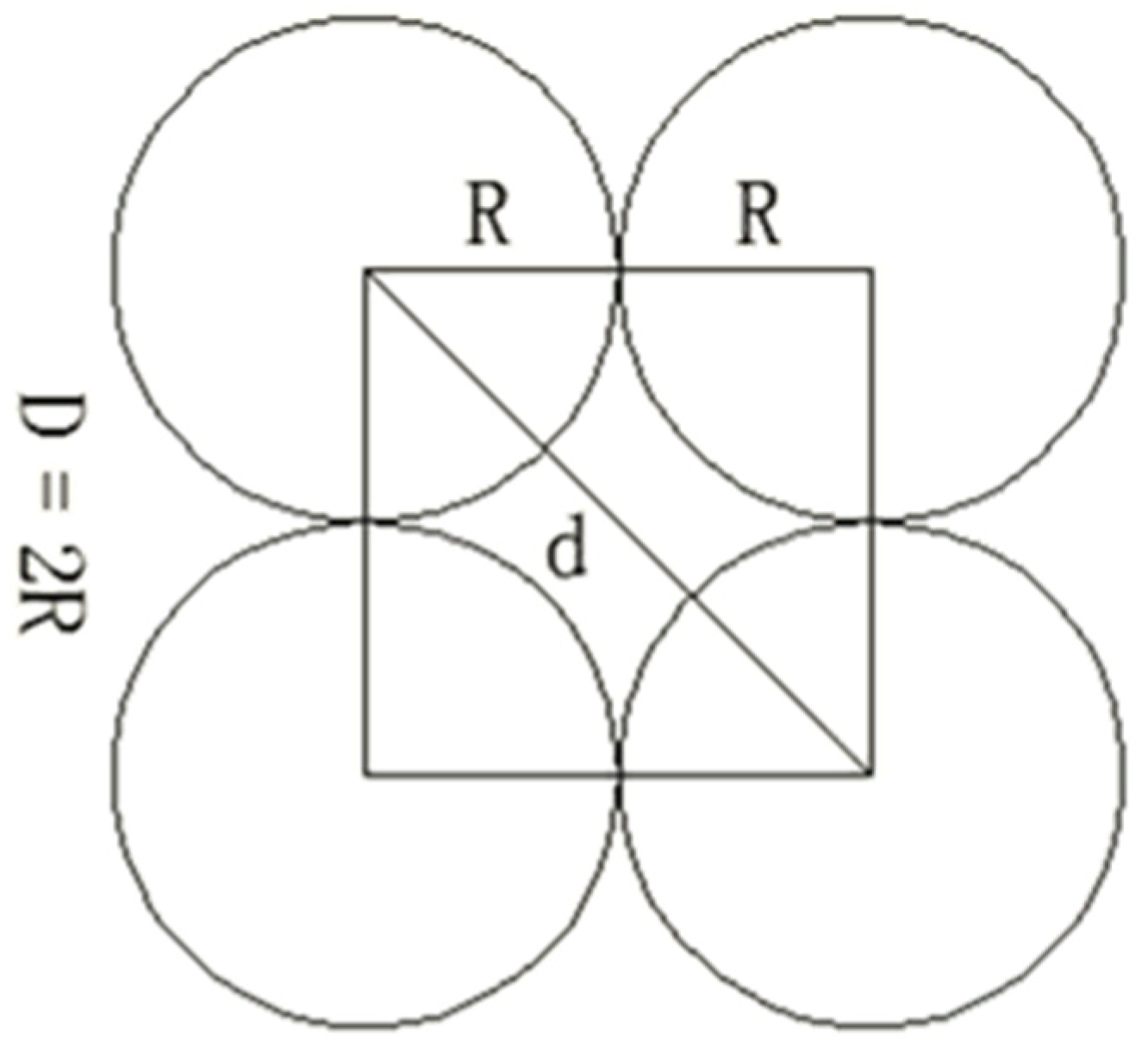
Petroleum Industry Standard SY/T 5329-2012 Allowable Median Particle SizeMinimum Pore Interception Capacity of the Filter Medium (According to the 1/3 Bridge Principle)
maximum valueminimum valuetriangular stackingsquare stacking
4.0 μm2.0 μm12.9 μm34.5 μm

