Study on Interfacial Surface in Modified Spray Tower
by
 ,
,
Marek Ochowiak
1,*, 
Sylwia Włodarczak
1,
Ivan Pavlenko
2 ,
,
Daniel Janecki
3,
Andżelika Krupińska
1 and
Małgorzata Markowska
1 1
Department of Chemical Engineering and Equipment, Poznan University of Technology, 60-965 Poznan, Poland
2
Department of General Mechanics and Machine Dynamics, Sumy State University, 40007 Sumy, Ukraine
3
Department of Process Engineering, University of Opole, 45-040 Opole, Poland
*
Author to whom correspondence should be addressed.
Processes 2019, 7(8), 532; https://0-doi-org.brum.beds.ac.uk/10.3390/pr7080532
Submission received: 22 July 2019
/
Revised: 7 August 2019
/
Accepted: 9 August 2019
/
Published: 13 August 2019
(This article belongs to the Section Chemical Processes and Systems)
Abstract
:This paper presents an analysis of the changes in interfacial surface and the size of droplets formed in a spray tower. The interfacial surface and the size of droplets formed are of fundamental importance to the performance of the equipment, both in terms of pressure drop and process efficiency. Liquid film and droplet sizes were measured using a microphotography technique. The confusors studied were classical, with profiled inside surface, and with double profiled inside surface. The liquids studied were water and aqueous solutions of high-molecular polyacrylamide (PAA) of power-law characteristics. The ranges of process Reynolds number studied were as follows: ReG ∈ (42,700; 113,000), ReL ∈ (170; 15,200). A dimensionless correlation for reduced Sauter mean diameter is proposed.
1. Introduction
Heat and mass transfer are widespread processes in the chemical industry. In these processes, spray towers have particular significance. In recent years, these constructions have been modified in search of high process efficiency, flexible hydraulic loading of simple construction, low friction factor, and low cost of investment. Application of new constructions is connected with the modification of existing tower systems under the influence of ecological aspects and improvement of technological and economical indexes.
Spray towers are characterized by a low friction factor of the flowing gas, large capability in changing the ratio of gas flow rate to liquid flow rate, and relatively low cost of investment. In spray towers, the processes of absorption of NH3, H2S, HF into water [1], SO2 into water or NaOH solution, Na2CO3 solution, CaCO3 solution [2], Cl2 into whitewash [3], and petrol vapor into oils [4] have been realized. Investigations have shown that the addition of creative foam substances to absorbent solutions increases the efficiency of removing pollutants from waste gases [5]. This method is used for the cleaning of gases from acid pollutants, such as SO2, HCl, HF, H2S, NOx [6], CO2 [7,8,9], or volatile organic compounds (VOCs) [10].
The elements that make up the interfacial surface in the spray tower are the conic distributors of liquid and confusors. Liquid falling from the cone is affected by aerodynamic forces in cocurrent gas flow, and streams feeding the confusors are therefore formed. At larger distances between the following stages of scrubber, the droplets of atomized liquid partially fall out and flow down as a film flow on the scrubber wall. In this connection, the interfacial surface being developed in the gas–liquid flow decreases along the scrubber. One of the most important parameters in the performance, calculation, and modeling of spray towers (spray columns, packed columns, Venturi scrubbers) is the droplet size. In the literature [11], we can find a few universal models for prediction of droplet sizes, such as pneumatic atomizers, which are used (with or without success) to predict the droplet diameter in spray towers.
In order to recover the interfacial surface, multistage towers are used. In the following stages, a similar mechanism of liquid atomization is applied, and the pressure drop is approximately of the same magnitude. Within the contracting contour of a confusor, the cocurrent gas–liquid flow has a rapid gain in velocity, which leads to the release of kinetic energy and the break-up of liquid stream into droplets at the outlet from the confusor [12]. In practice, cone-shaped confusors are applied when the maximal gas velocity considerably exceeds 30 ms−1. In industrial constructions, the following geometric characteristics of confusors are used: an angle of confusor inclination α = 45°–60° and orifice factor of φ = 0.09–0.36, where
The hydrodynamic efficiency of the scrubber can be estimated by specific energy consumption on the formation of the unit interfacial surface. In practical cases of mass transfer, it can be estimated by the expenditure of energy on the unit mass of the transferred component. A reduction in power consumption can be obtained by decreasing the pressure drop or raising the quality of atomization. On the other hand, if the angle of declination and/or orifice factor of the confusor is increased and the pressure drop is decreased, the dimensions of the interfacial surface developed will also be reduced. This is the result of a decrease in gas velocity in the throat cross section of the confusor [12].
The literature on the multiplicity of hydrodynamics and mass transfer processes in spray towers is not large [11,12]. The investigations that have been carried out until now have mainly dealt with two things: laboratory-scale installations and analysis of transfer processes concerning single droplets of a certain diameter. Study on the latter [12] has provided much valuable information about oscillations in the shapes of falling droplets and the mass fluxes existing in gas and liquid phases. However, the results of these studies cannot be directly used to describe the processes in spray towers as they have many limitations. In spray towers, a great variety of droplets of different sizes is present. When coalescing droplets fall, part of them hit the tower wall and flow down in a thin liquid film layer. Here, the mechanism of complex processes is considerably more complicated to describe. When the number of droplets is large, additional interference and circulation take place in the gas phase.
The results of this study can be helpful in the analysis of different processes realized in spray towers, such as absorption processes, drying, cleaning, and spray drying. For example, solid particles may be produced in spray processes by atomization of liquid feed materials and successive consolidation of the droplets. Targeted powder properties (particle size, shape, morphology, structure, etc.) can be obtained by controlling the spray process (spray tower geometries, process parameters, etc.). The modifications of the spray tower can contribute to reduced energy consumption. In this study, the confusors studied were classical, with profiled inside surface, and with double profiled inside surface.
2. Materials and Methods
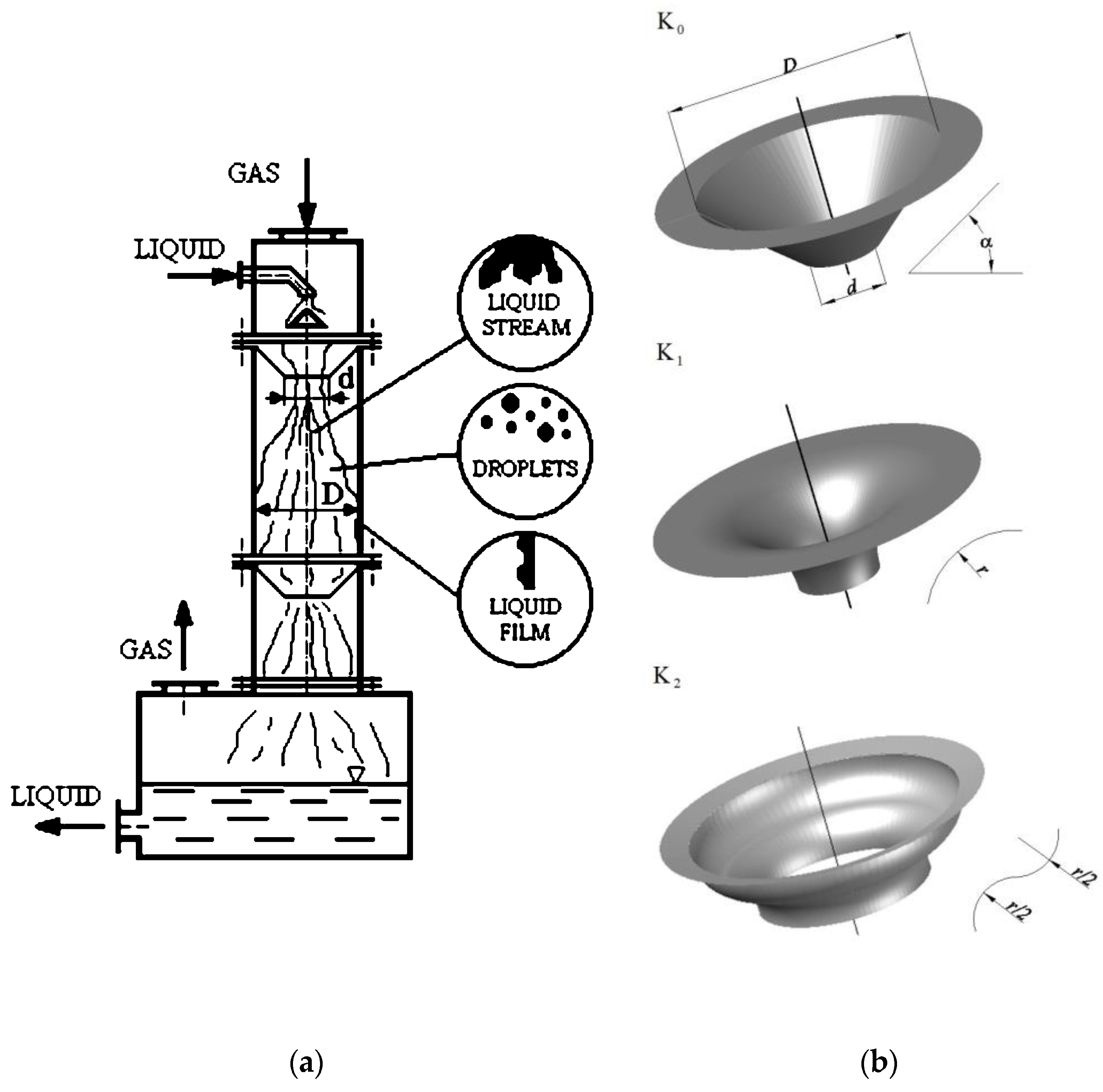
The main elements of the test installation were as follows: two-stage absorber; liquid separator; air heater; cyclonic temperature stabilizer; and measurement units of airflow, humidity, temperatures, and pressure drop. A cocurrent spray tower equipped with cone-shaped confusors was used to evaluate the interfacial gas–liquid surface (Figure 1). The following confusors were studied: classical cone-shaped (K0), with profiled inside surface (K1), and with double profiled inside surface (K2). The characteristics of the tested construction were as follows: confusor diameter d = 0.0333 m, orifice factor φ = 0.137, and angle of confusor inclination α = 45°. The experiments were performed in a poly (methyl methacrylate) tower that was 0.09 m in diameter and 1.2 m high, and the active volume V of the tower was 7.63 dm3. A high-molecular polyacrylamide (PAA) aqueous solution with a concentration of 1000 ppm and water were studied. The polymer solution was characterized by power-law characteristics (Ostwald de Waele model):
where τw is the wall shear stress, K′ is the power-law liquid factor, and γw is the wall shear rate.
The ranges of Reynolds number [13] studied were ReG ∈ (42,700; 130,000) and ReL ∈ (170; 15,200):
where MG is the mass flow rate of gas, d is the diameter of the confusor throat, μG is the viscosity of gas, w is the mean flow velocity of liquid, and ρL is the density of liquid. The mean velocity of gas/liquid phase was calculated in the cross section of the confusor orifice (for diameter d).
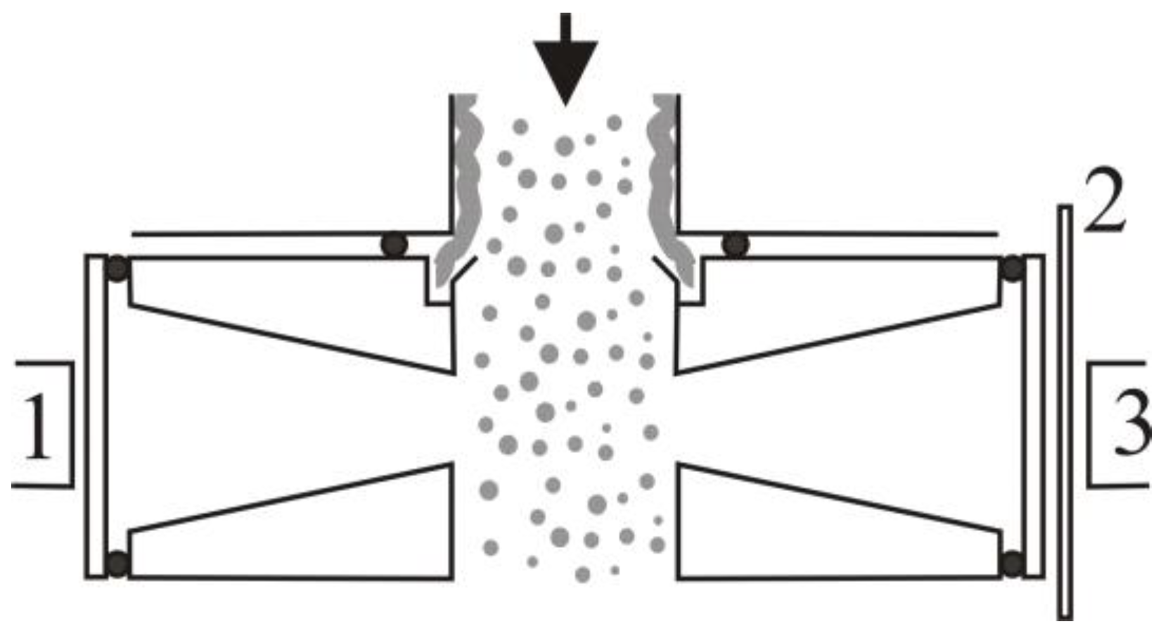
The research on interfacial surface consisted of determining surface changes on the air–liquid phase boundary depending on the gas and liquid volume rates. The results of the experiments for modified confusors were compared with the results for classical confusor K0. The visualization of the interfacial surface studied was carried out using a photographic method with a CASIO QV-3000EX/Ir digital camera (Casio Electronic Manufacturing Co., Ltd., Miyadera, Japan), resolution of 2048 × 1536 pixels). The camera is equipped with specialized software developed by CASIO and enables professional image processing on a PC computer. The photos of the surface below the confusor were taken with the camera at a distance of 17 cm below the lower edge of the confusor (the average value of the interfacial surface is approximately equal to the local value at a distance of 16–18 cm) [13]. Photos of drops in the core of the column were taken after modification of the column (Figure 2) according to [11].
This paper presents the results of the experimental study on two-phase gas–liquid flow using the digital picture processing method (DPPM). The identification and analysis of the falling droplets and their size were carried out in a cocurrent spray column in Corel Draw 9.0 (Corel Corporation, Ottawa, ON, Canada) and Image-Pro Plus programs (Media Cybernetics Inc., Rockville, MD, US). The DPPM procedure consisted of picture conversion to the grey scale, framing, outlining and finding an edge. In the next stage of measurements, the thickness of the layer of liquid falling down the vessel wall was determined, and the grey level value was analyzed. The total size of the interfacial surface was the sum of the surface of liquid film and of all droplets in the core of the column. A total of 120 digital photos of the base droplets existing in the column core were taken, and they showed about 6000 droplets of various shapes and dimensions.
3. Results
The experiments for air flow in a column equipped with all the studied confusors showed that the friction factor values were independent of gas Reynolds number and dependent on the construction used. It was found that, for the cone-shape confusor K0, the characteristic Euler number for gas flow, i.e.,
was equal to EuG = 0.81. For air flow through modified confusors, the following friction factor values were obtained: K1 EuG = 0.58 and K2 EuG = 0.59. The modified constructions caused a decrease in flow resistance from 27.2% to 28.4% with regard to the cone-shaped construction. It was found that the pressure drop for geometrically modified confusors was smaller than in the case of classical solution (cone confusor with smooth wall). With the increase in Reynolds number for gas, for given values of Reynolds number for liquid, the Euler number decreased. For two-phase flow, the Euler number is defined as follows:
and described by a correlation as follows:
Table 1 shows the values of constants C and EuG in Equation (7).
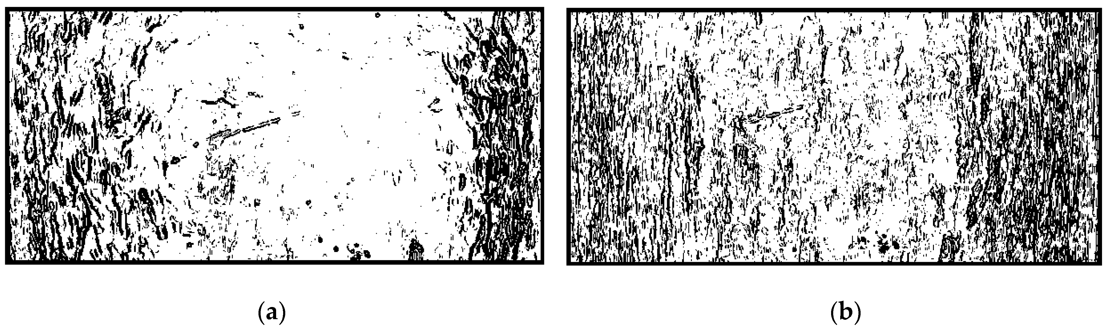
A visualization of the liquid film surface is shown in Figure 3. It can be seen that the rippling of the film surface increased with the increase in gas volume rate. When the fraction of liquid flowing down the film on the wall became higher, the small part of the liquid became atomized into droplets. As a result, the size of the interfacial surface decreased. The rippling of the film surface had an influence on the increase in the interfacial surface. The wave in the falling liquid film and the single droplets can be observed in the photos. The total size of the interfacial surface was the sum of the surface of liquid film and all droplets in the core of the tower. The liquid film surface at small liquid volume rate is shown. The turbulent structure of the surface is clearly evident. The waves in the liquid had irregular form, and this irregularity was more apparent when the gas volume rate was higher. This is probably the result of swirl generation in the flowing gas stream. Lengthwise waves were formed at large liquid volume rates. This is possibly the result of excess liquid in the layer near the wall. The surface of the liquid film for the classical confusor K0 was comparable to the one for the modified confusors.
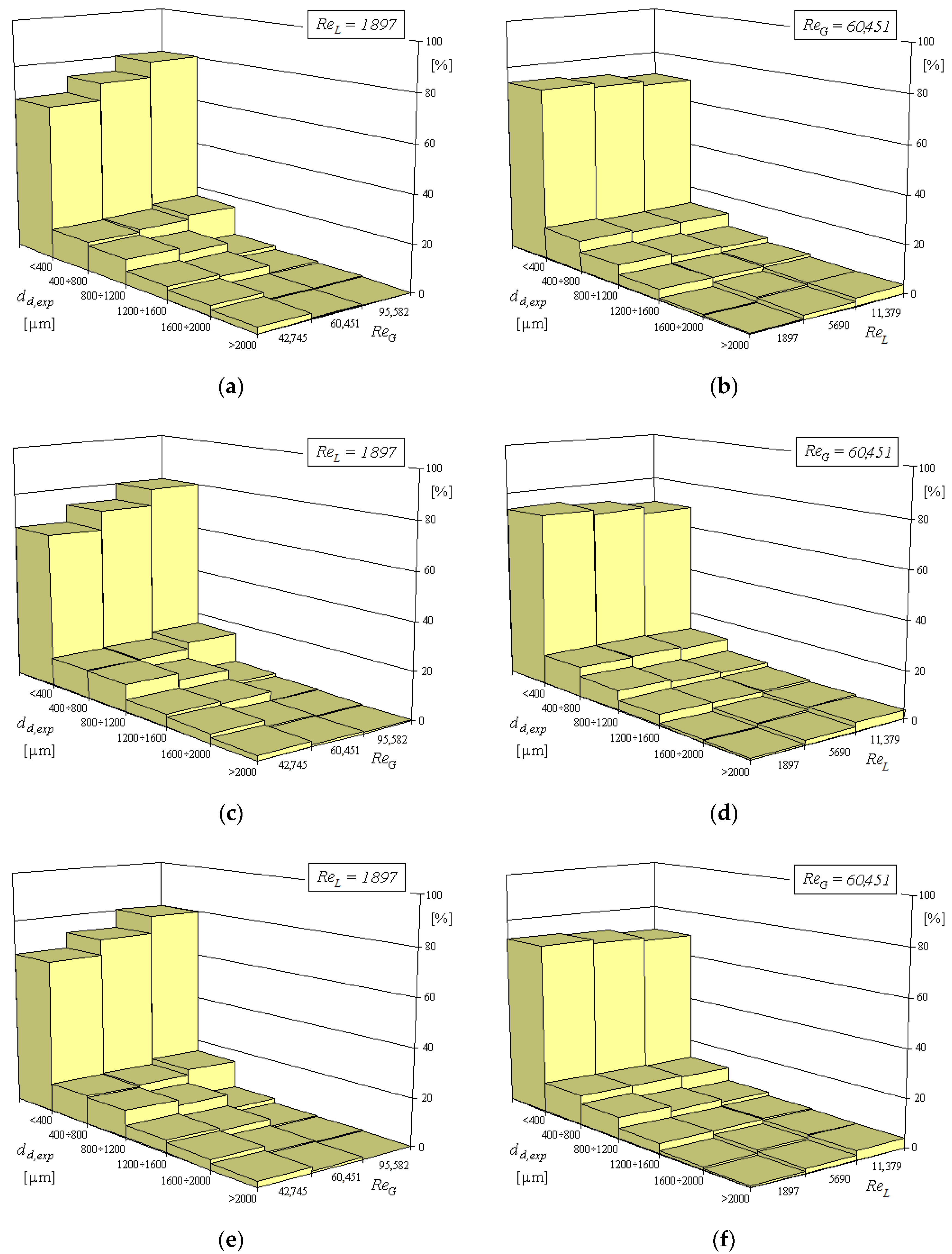
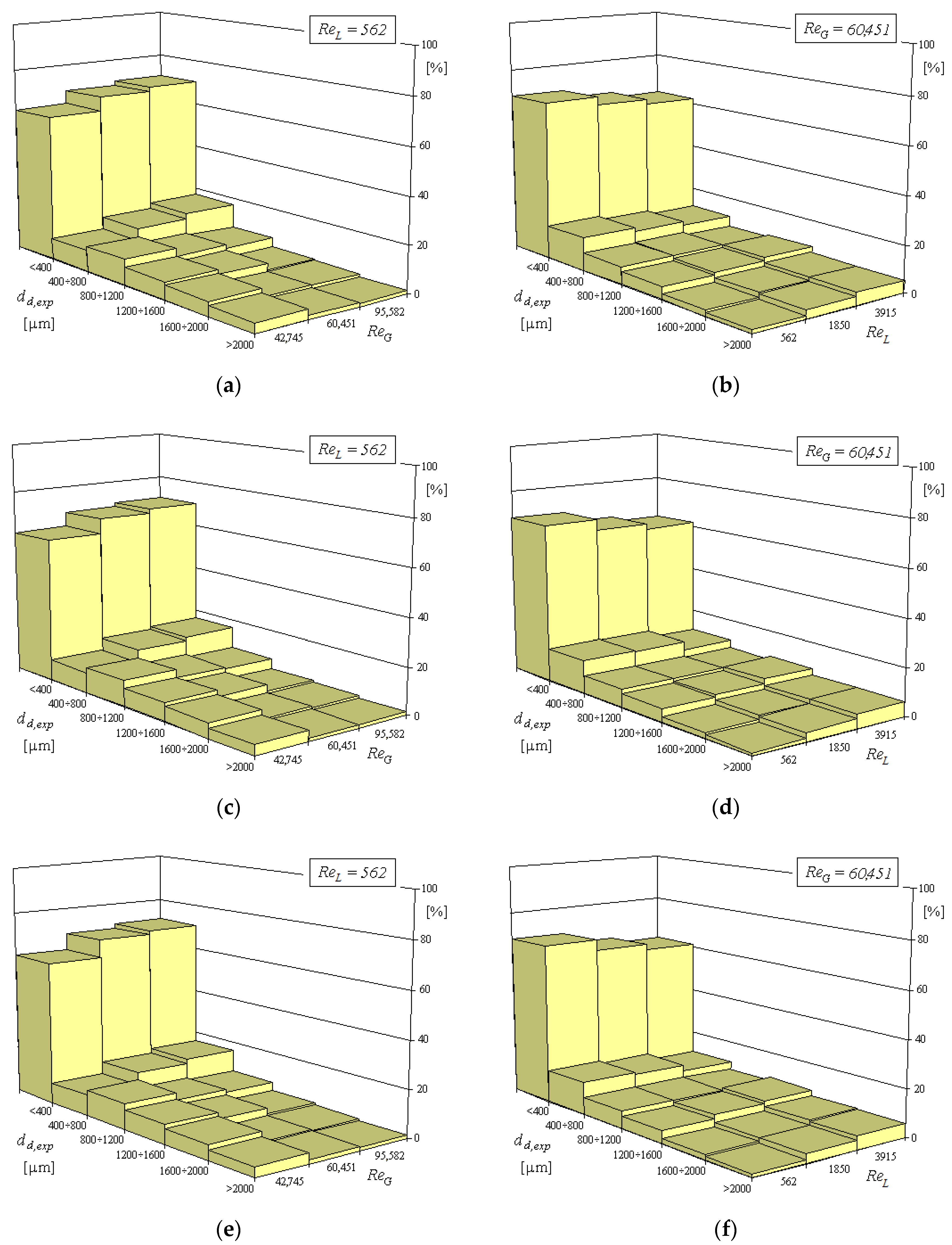
An analysis of the photos of liquid droplets in the core of the tower showed that the droplets that were formed during the liquid atomization had very different sizes. The smallest droplets had diameters of the order of ten micrometers. However, not all the liquid volume was in droplet form. Part of the liquid was in the form of thin streams, which could burst into droplets. An increase in the gas volume rate decreased the number of larger droplets and increased the number of smaller droplets (size under 800 μm). An increase in liquid volume rate increased the number of larger droplets (size over 1200 μm) and decreased the number of smaller droplets (size under 400 μm). Such tendency was observed in both air–water and air–polymer solution systems.
Sauter diameter d32 is calculated as the following ratio:
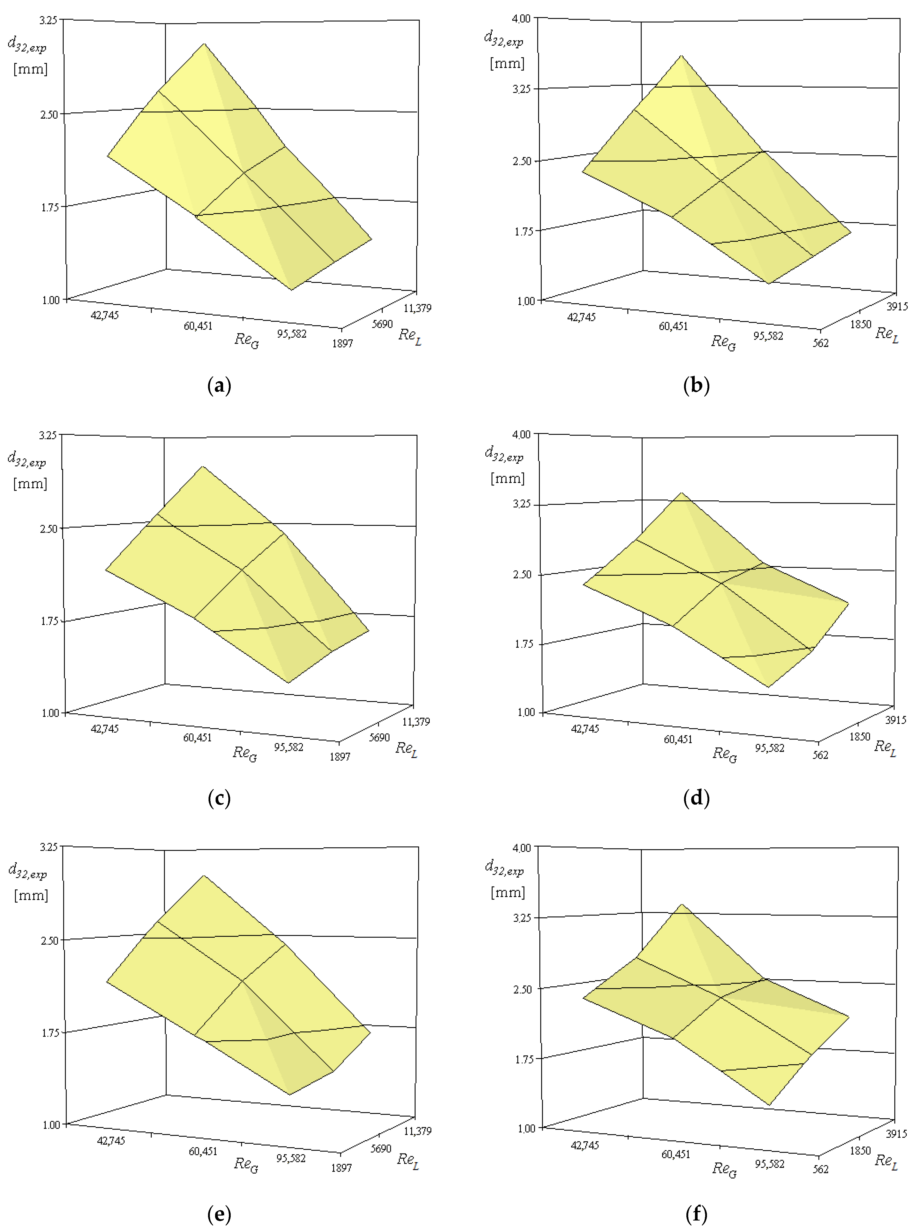
In Figure 4 and Figure 5, the relationship between the Sauter diameter d32 and the Reynolds numbers for gas ReG and liquid ReL are shown. The Sauter diameter for the air–liquid systems investigated decreased with the increase in Reynolds number for the gas phase and increased with the increase in Reynolds number for the liquid phase. Considerable dispersion in sizes of droplets was observed for all the confusors investigated (Figure 6). The size of the interfacial surface was practically independent of the construction of the confusor. At given values of Reynolds numbers, the surface waviness and mean droplet size were compared, and they were independent of the type of confusor used. This suggested that the values of the developed interfacial surface were comparable for all the confusors that were tested. An analysis of the photos of the droplets forming in air–water and air–polyacrylamide water solutions showed that the droplets were bigger in air–polymer solution. This is probably the result of higher pressure drop during the tear of liquid into droplets.
High molecular weight of polymer (flexible in the polyacrylamide case) added to the spray solvent (water) involves changes in the viscosity of the liquid and in the character of the flow [14,15]. Other parameters, such as the size of droplets, the distribution of liquid in the stream of droplets, and the characteristics of sprayer also change. The results show that there are complex, but qualitatively predictable, interactions between the rheological properties of the liquids and the atomization behavior. Furthermore, it has been clearly demonstrated that low concentrations of polymer additives may have profound effects on the spray pattern produced by typical spray tower systems.
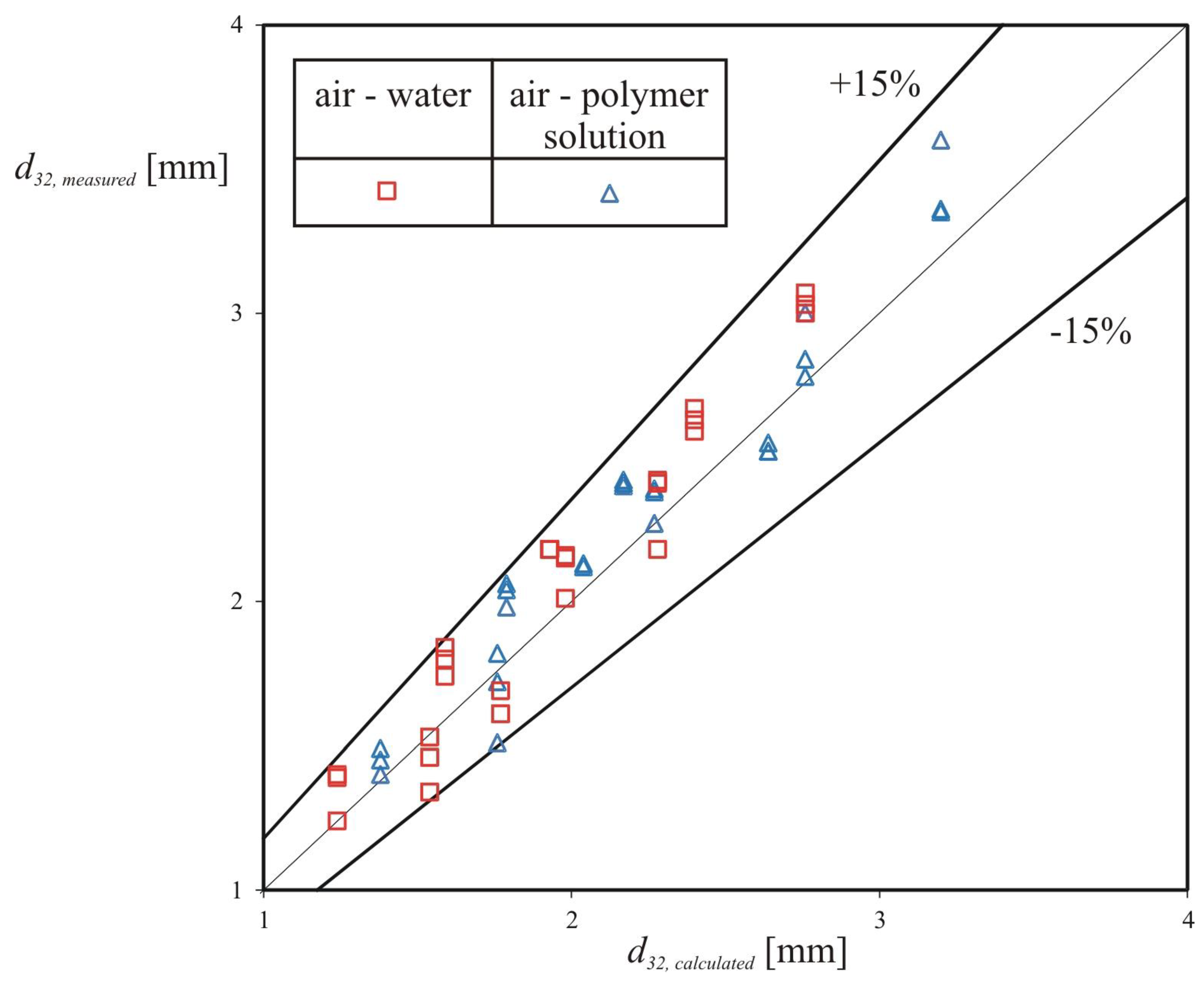
The size of droplets depends on both the molecular weight of the polymer and the character of the polymer chain (rigid, semirigid, and flexible). High molecular weight of polymers causes a decrease in the number of small droplets. As a result, the Sauter diameter is increased. Investigations on different polymers and different spray constructions have shown that the greatest improvement of spray characteristics is obtained for small concentration of flexible polymer–water solutions [16]. The mechanism by which such additives act in this respect is generally not well understood [16]. It has been observed that in air–water systems, droplets of diameters lower than those in the polymer solutions are formed [17,18]. It has been found that the Sauter diameter can be determined from the following correlation:
where δe describes the equivalent linear dimension taking into account the rheological properties of the liquid phase:
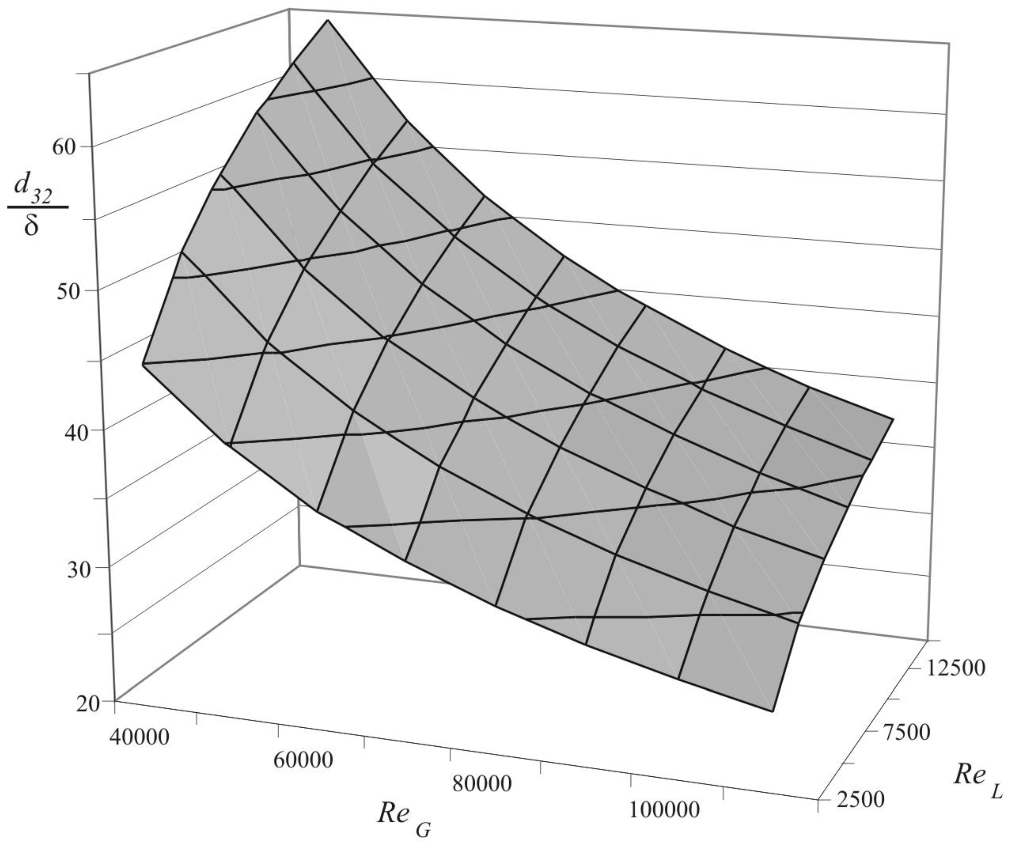
The analysis was performed in Statistica software (TIBCO Software Inc., Palo Alto, CA, US). A comparison of the measured drop size and the one calculated from Equation (9) is shown in Figure 7. In Figure 8, the relationship between reduced Sauter diameter d32,r and Reynolds number for gas ReG and Reynolds number for liquid ReL is presented. An increase in the gas flow rate or a decrease in the liquid flow rate causes an increase in both the wave deformation on the liquid film and the number of small droplets.
4. Conclusions
The size of droplets formed in spray towers is of fundamental importance to the performance of the equipment, both in terms of pressure drop and dust removal efficiency. In this study, drop sizes in a cylindrical, modified spray tower were measured using a photography technique. The investigation showed that the rippling of the film surface increased with the increase in gas volume rate. When the mass of liquid falling along the wall of the spray tower became larger, a small fraction of liquid was atomized into single droplets. As a result, the interfacial surface decreased. The undulation of the film flow had an influence on the increase in interfacial surface.
The liquid droplets formed during the liquid atomization had very different sizes. An increase in the gas flow rate or a decrease in the liquid flow rate caused an increase in both the wave deformation on the liquid film and the number of small droplets. It was shown that the droplets formed in an air–polyacrylamide solution system were larger than those in an air–water system. An increase in the Sauter diameter was also observed.
For all modified distributors, a comparable size of interfacial surface with respect to the classical one was obtained. The drop formation conditions in the two types of gas–liquid systems studied were different. The atomization of water was easier than that of the polymer solution.
It has been shown that geometrically modified confusors involve energy saving and are comparable with classical solution, i.e., the gas–liquid interfacial surface. Taking into account much lower friction factors [19], a lack of flooding phenomena, simple construction, and great operational reliability (immunity to load change, deposit), the modified solution is recommended for industry-scale application.
Author Contributions
M.O. and S.W. conceived and designed the experiments; M.O., S.W., A.K. and M.M. performed the experiments; M.O., S.W., I.P., D.J., A.K., and M.M. analyzed the data; M.O., S.W., I.P., D.J., A.K., and M.M. contributed reagents/materials/analysis tools; M.O., I.P., D.J. and A.K. wrote the paper.
Acknowledgments
This research was supported by the Ministry of Education and Science of Poland through grant PUT 03/32/SBAD/0902.
Conflicts of Interest
The authors declared no potential conflicts of interests with respect to the research, authorship, and publication of this article.
References
- Budanov, V.I.; Rybakov, L.A.; Gladkij, A.V. Method of the removal of sulphur dioxide from waste gases. Khimicheskaja Promyshlennost 1976, 52, 678–681. [Google Scholar]
- Brogren, C.; Karlsson, H.T. Modeling the absorption of SO2 in spray scrubber using the penetration theory. Chem. Eng. Sci. 1997, 52, 3085–3099. [Google Scholar] [CrossRef]
- Hehlmann, J.; Mokrosz, W. Research into desulphurisation efficiency in a wet method employing a concurrent column packed with the cellular packing. Chem. Eng. Appar. 1993, 2, 15–20. [Google Scholar]
- Szklarczyk, M. Biological Treatment of Waste Gases; Wroclaw University of Technology Publishing House: Wroclaw, Poland, 1991. [Google Scholar]
- Kuzniar, J.J.; Czubak, A.; Szczesniak, S. Removal of sulphur dioxide from waste gases Solinox. In Proceedings of the XVI Polish Conference of Chemical and Process Engineering, Kraków-Muszyna, Poland, 22–25 September 1998; pp. 289–292. [Google Scholar]
- Warych, J. Gas Purification, Processes and Apparatus; Wydawnictwo Naukowo-Techniczne: Warszawa, Poland, 1998. [Google Scholar]
- Bandyopadhyay, A.; Biswas, M.N. CO2 capture in a spray column using a critical flow atomizer. Sep. Purif. Technol. 2012, 94, 104–114. [Google Scholar] [CrossRef]
- Qing, Z.; Yincheng, G.; Zhenqi, N. Experimental studies on removal capacity of carbon dioxide by a packed reactor and a spray column using aqueous ammonia. Energy Procedia 2011, 4, 519–524. [Google Scholar] [CrossRef] [Green Version]
- Kuntz, J.; Aroonwilas, A. Mass-transfer efficiency of a spray column for CO2 capture by MEA. Energy Procedia 2009, 1, 205–209. [Google Scholar] [CrossRef]
- Meyer, M.; Hendou, M.; Prevost, M. Simultaneous heat and mass transfer model for spray tower design: Application on VOC’s removal. Comput. Chem. Eng. 1995, 19, 277–282. [Google Scholar] [CrossRef]
- Alonso Fernandez, D.; Goncalves, J.A.S.; Azzopardi, B.J.; Coury, J.R. Drop size measurements in Venturi scrubbers. Chem. Eng. Sci. 2001, 56, 4901–4911. [Google Scholar] [CrossRef]
- Koziol, K.; Ziolkowski, W. Two-phase pressure drop in modified co-current spray scrubber. Chem. Process Eng. 1989, 10, 345–357. [Google Scholar]
- Ziolkowski, W. The Study of Hydrodynamics of Co-Current Spray Scrubber. Ph.D. Thesis, Poznan University of Technology, Poznan, Poland, 1983. [Google Scholar]
- Metzner, A.B.; Reed, J.C. Flow of non-Newtonian fluids—Correlation of the laminar, transition, and turbulent-flow regions. AIChE J. 1955, 1, 434–440. [Google Scholar] [CrossRef]
- Harrison, G.M.; Mun, P.R.; Cooper, G.; Boger, D.V. A note on the effect of polymer rigidity and concentration on spray atomization. J. Non-Newton. Fluid Mech. 1999, 85, 93–104. [Google Scholar] [CrossRef]
- Mun, P.R.; Young, B.W.; Boger, D.V. Atomisation of dilute polymer solutions in agricultural spray nozzles. J. Non-Newton. Fluid Mech. 1999, 83, 163–178. [Google Scholar] [CrossRef]
- Broniarz-Press, L.; Ochowiak, M. Studies on interfacial surface gas–power-law liquid in two-stage spray absorber. Chem. Eng. Appar. 2003, 5, 29–31. [Google Scholar]
- Ochowiak, M. Analysis of the Flow Phenomena in Modified Spray Absorbers. Ph.D. Thesis, Poznan University of Technology, Poznan, Poland, 2002. [Google Scholar]
- Ochowiak, M.; Broniarz-Press, L. The flow resistance and aeration in modified spray tower. Chem. Eng. Process. Process Intensif. 2011, 50, 345–350. [Google Scholar] [CrossRef]
Figure 1.
Scheme of the spray cascade cocurrent absorber: (a) Confusor constructions studied; (b) K0—classical, K1—with profiled inside surface, K2—with double profiled inside surface.
Figure 1.
Scheme of the spray cascade cocurrent absorber: (a) Confusor constructions studied; (b) K0—classical, K1—with profiled inside surface, K2—with double profiled inside surface.

Figure 2.
Schematic representation of liquid film removal arrangement using slot modification of the column based on [11]. 1—digital camera, 2—screen, 3—flash lamps.
Figure 2.
Schematic representation of liquid film removal arrangement using slot modification of the column based on [11]. 1—digital camera, 2—screen, 3—flash lamps.

Figure 3.
Photos of the liquid film in the tower equipped with cone-shape confusor K0: (a) ReG = 74,037, ReL = 632; (b) ReG = 74,037, ReL = 11,379.
Figure 3.
Photos of the liquid film in the tower equipped with cone-shape confusor K0: (a) ReG = 74,037, ReL = 632; (b) ReG = 74,037, ReL = 11,379.

Figure 4.
The distribution of drop size in the air–water system for the confusors studied: (a,b) K0; (c,d) K1; and (e,f) K2.
Figure 4.
The distribution of drop size in the air–water system for the confusors studied: (a,b) K0; (c,d) K1; and (e,f) K2.

Figure 5.
The distribution of drop size in the air–polymer solution system for the confusors studied (a,b) K0; (c,d) K1; and (e,f) K2.
Figure 5.
The distribution of drop size in the air–polymer solution system for the confusors studied (a,b) K0; (c,d) K1; and (e,f) K2.

Figure 6.
The Sauter diameter for air–water system (a,c,e) and air–polyacrylamide (PAA) solution (b,d,f). (a,b) K0; (c,d) K1; and (e,f) K2.
Figure 6.
The Sauter diameter for air–water system (a,c,e) and air–polyacrylamide (PAA) solution (b,d,f). (a,b) K0; (c,d) K1; and (e,f) K2.

Figure 7.
Comparison of measured drop size with calculated drop size from Equation (9).

Figure 8.
The relationship between reduced Sauter diameter d32,r and ReG and ReL.


Table 1.
Constants C and EuG in Equation (7).
| Two-Phase System | Confusor | EuG | C |
|---|---|---|---|
| Air–water | K0 | 0.81 | 10.448 |
| K1 | 0.58 | 10.024 | |
| K2 | 0.59 | 11.486 | |
| Air–aqueous solution of polyacrylamide | K0 | 0.81 | 27.534 |
| K1 | 0.58 | 25.026 | |
| K2 | 0.59 | 27.346 |
© 2019 by the authors. Licensee MDPI, Basel, Switzerland. This article is an open access article distributed under the terms and conditions of the Creative Commons Attribution (CC BY) license (http://creativecommons.org/licenses/by/4.0/).
Share and Cite
MDPI and ACS Style
Ochowiak, M.; Włodarczak, S.; Pavlenko, I.; Janecki, D.; Krupińska, A.; Markowska, M. Study on Interfacial Surface in Modified Spray Tower. Processes 2019, 7, 532. https://0-doi-org.brum.beds.ac.uk/10.3390/pr7080532
AMA Style
Ochowiak M, Włodarczak S, Pavlenko I, Janecki D, Krupińska A, Markowska M. Study on Interfacial Surface in Modified Spray Tower. Processes. 2019; 7(8):532. https://0-doi-org.brum.beds.ac.uk/10.3390/pr7080532
Chicago/Turabian StyleOchowiak, Marek, Sylwia Włodarczak, Ivan Pavlenko, Daniel Janecki, Andżelika Krupińska, and Małgorzata Markowska. 2019. "Study on Interfacial Surface in Modified Spray Tower" Processes 7, no. 8: 532. https://0-doi-org.brum.beds.ac.uk/10.3390/pr7080532
Note that from the first issue of 2016, this journal uses article numbers instead of page numbers. See further details here.