Accelerating Biologics Manufacturing by Modeling: Process Integration of Precipitation in mAb Downstream Processing


Institute for Separation and Process Technology, Clausthal University of Technology, Leibnizstraße 15, 38678 Clausthal-Zellerfeld, Germany
*
Author to whom correspondence should be addressed.
Processes 2020, 8(1), 58; https://0-doi-org.brum.beds.ac.uk/10.3390/pr8010058
Submission received: 27 November 2019
/
Revised: 19 December 2019
/
Accepted: 30 December 2019
/
Published: 2 January 2020
(This article belongs to the Section Biological Processes and Systems)
Abstract
:The demand on biologics has been constantly rising over the past decades and has become crucial in modern medicine. Promising approaches to cope with widespread diseases like cancer and diabetes are gene therapy, plasmid DNA, virus-like particles, and exosomes. Due to progress that has been made in upstream processing (USP), difficulties arise in downstream processing and demand for innovative solutions. This work focuses on the integration of precipitation using a quality by design (QbD) approach for process development. Selective precipitation is achieved with PEG 4000 resulting in an HCP depletion of ≥80% respectively to IgG. Dissolution was executed with a sodium phosphate buffer (pH = 5/50 mM) reaching an IgG recovery of ≥95%. However, the central challenge in process development is still an optimal process design, which is transferable for a broad molecular variety of new products. This is where rigorous modeling becomes vital in order to generate digital twins to support early-stage process development and reduce the experimental overhead. Therefore, a model development and validation concept for construction of a process model for precipitation is also presented.
1. Introduction
Due to the rising demand of biopharmaceuticals and the progress that has been made in upstream processing (USP) over the past decades, downstream processing (DSP) has to overcome bottlenecks in purification to handle constantly increasing titers and process volumes [1,2]. Protein A chromatography was identified as the critical point in monoclonal antibody (mAb) purification due to its costs for resins and relatively low capacity compared to alternative chromatography steps like ion exchange chromatography (IEX) [3]. Moreover, Protein A resins are not tolerant towards cleaning agents, on account of fragility of the immobilized Protein A. All of this results in a limited lifecycle and a demand on finding new solutions for unit operations or the reactivation of already existing ones [4,5,6,7,8].
Precipitation might have all it takes to overcome the disadvantages mentioned above [9]. It is a relatively simple unit, which can be used for volume and impurity reduction. It does not need a complex equipment setup but rather a continuous stirred tank reactor (CSTR) or a tubular reactor as well as a filter for solid–liquid separation. Further, precipitation is described as quite a fast process, which leads to shortened dwell times. Furthermore, it is able to deal with high process volumes and even more important with rising titers. In addition to that, it is easy scalable and various working groups have already proven the feasibility of continuous operation [10,11,12,13].
Alongside the promising advantages for purification, several obstacles must be overcome first. The biggest disadvantage is the selectivity of precipitation. Some working groups have paid attention to affinity precipitation by addition of ligands [14,15,16]. However, the problem in this context is the exposition of the target, which means an additional purification step as usual as well as the elimination of the ligand [17,18]. The second challenge is to retain the biological activity of the antibodies. Small structural changes, for example in glycosylation, may cause ineffectiveness [19,20,21,22,23,24,25].
Precipitation always deals with a shift of solubility of either side components or the target protein. This can be reached by changing properties of the solvent, the target protein, or through affinity bonding. Properties of the solvent are influenced by addition of organic solvents, acids, salts (chaotrop and kosmotrop), as well as polymers like polyethylene glycol (PEG) [26,27,28]. Organic acids are used to precipitate impurities like DNA and host cell proteins (HCPs) [29]. Salts can influence proteins in two direction. They either stabilize them through a salting-in effect, occurring while ionic strength is below 100 mM, or accelerate precipitation based on the salting-out effect, which eventuates by an ionic strength above 100 mM [17,30]. This range is strongly dependent on the salt selected and can vary tremendously. For isolation of large proteins like antibodies (150 kDa), PEG precipitation has shown promising results. Even though several working groups investigated [13,28,31,32,33,34,35,36,37] this phenomenon and built models to describe its behavior, the mechanism of PEG precipitation is not understood well enough yet. Nevertheless, two theories exist to explain its functionality: The theory of attractive depletion [38] and the theory of excluded volume [39]. The theory of attractive depletion describes protein precipitation as a force of osmotic pressure that is mainly caused by steric exclusion of the PEG molecules. The theory of excluding volume is based on the assumption that polymers occupy solvent molecules, which leads to a local supersaturation followed by precipitation.
In case of biologics purification, two strategies are available for precipitation. On one hand, it can be utilized to precipitate side components like DNA and HCPs while keeping the target protein in solution to circumvent subsequent dissolution and difficulties like degradation. Nevertheless, it can be challenging to precipitate a bulk of impurities with unknown and diverse properties. On the other hand, precipitation can be used to isolate the target protein itself, which seems more convenient, because parameters can be chosen optimal for the target component.
In a multi-stage approach, both aims are combined. Firstly, the content of side components is reduced by lowering their solubility by variating pH-value and ionic strength and, secondly, the target molecule is precipitated through addition of organic solvents like ethanol (EtOH). In this case, the amount of co-precipitating HCPs is reduced before the target protein is precipitated.
Currently, precipitation is well implemented as an inherent part of sample preparation in analytics [40] but not yet common in downstream processing (DSP) of biologics due to the described obstacles above [41]. Thus far, precipitation is used in industrial scale for purification of Insulin and EPO [3], but recent research is investigating in implementing precipitation as a unit operation in DSP for biologics [28,31,32,35,36,42].
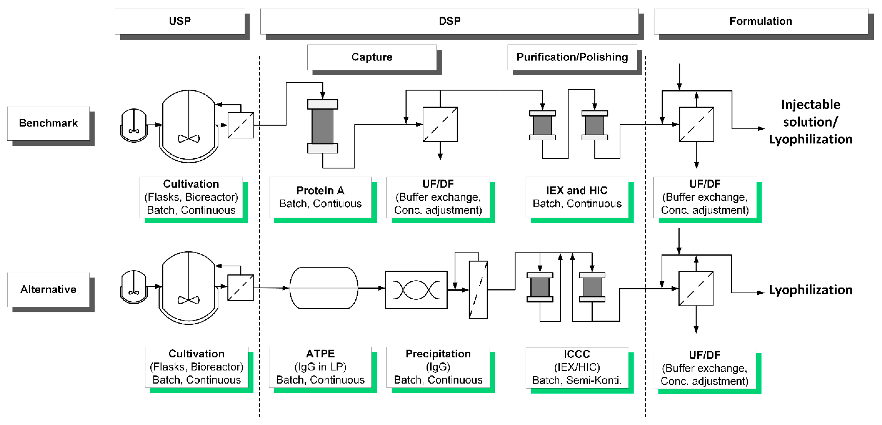
New medication approaches like exosomes, plasmid DNA, virus-like particles, and gene therapy need flexible processes and purification solutions that are read to use. Therefore, platform processes are demanded to enable a fast admission of new products to the pharmaceutical market. In this study, a novel approach for precipitation as an alternative capture is presented using the example of monoclonal antibodies (mAb). The benchmark as well as the alternative process are shown in Figure 1. The capture is conducted as a combination of aqueous two-phase extraction (ATPE) and a subsequent precipitation of the target protein IgG. ATPE serves as first clarification step to deplete high molecular weight impurities (HMWI) and DNA, which is an essential preparation for the following precipitation. Precipitation performance is influenced by the amount of present side components, which becomes vital in dissolution [43].
2. Process Integration Applying Quality by Design
Due to varying manufacturing processes in different companies, several entities like FDA (U.S. Food and Drug Administration), EMA (European Medicines Agency), PDA (Parenteral Drug Association), and ICH (International Council for harmonization of Technical Requirements for Pharmaceuticals for Human Use) claimed a coherent manufacturing practice to ensure a consistent product quality. Therefore, the quality by design approach (QbD) was introduced, which is becoming the new standard procedure for process development practice [44,45,46,47,48].
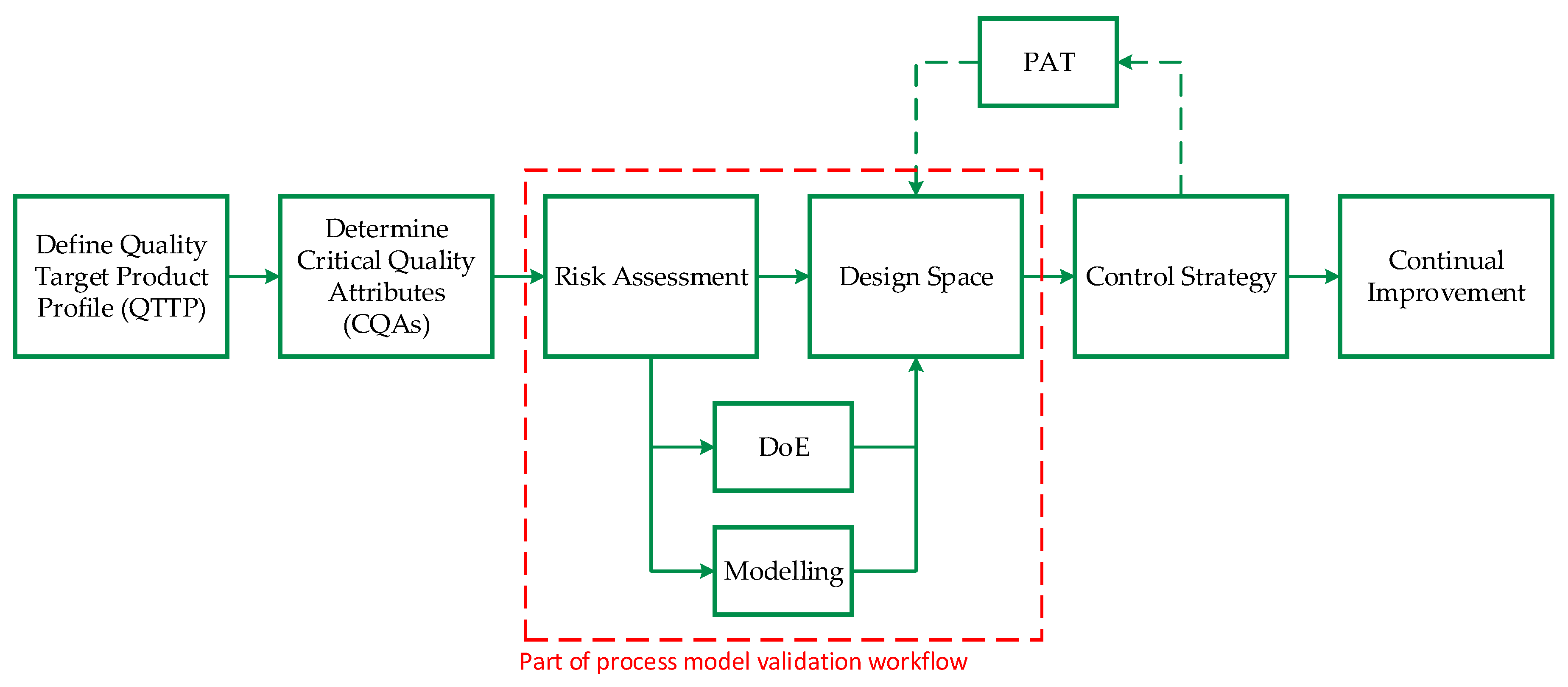
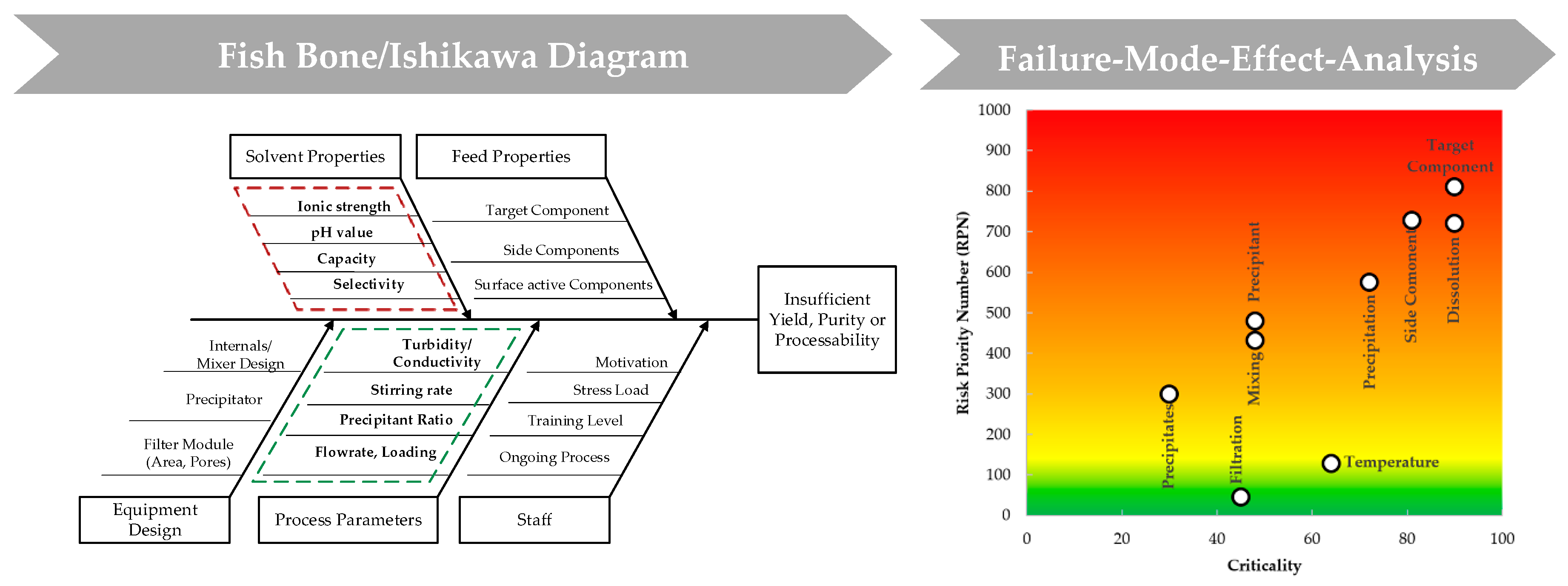
Sixt et al. [49] proposed a general approach based on validated process modelling, shown in Figure 2, to find the optimal operating parameters to result in the demanded product quality. At first, a quality target product profile (QTPP) is defined, followed by the determination of critical quality attributes (CQAs). Subsequently, a risk assessment is conducted, which is part of a risk management with the purpose of establishing known and hypothetical links between resources, equipment, and operating parameters. FDA, EMA, PDA, and ICH suggested tools like the Ishikawa diagram, shown in Figure 3, as well as the execution of a failure-mode-effect-analysis (FMEA) for the implementation of a new process using the QbD approach.
To ensure the demanded product quality, a design space is derived from one parameter at a time studies in the scope of FMEA. Traditionally, this determination is done by empirical approaches like high-throughput experiments or design of experiments (DoE) but can also be supported through simulation aiming to reduce the experimental overhead. This is where mechanistic modeling becomes vital as a powerful tool to save time and monetary resources to investigate new process parameter ranges. Finally, a control strategy is implemented to monitor and control the process via process analytical technology (PAT).
In this work, a QbD approach will be applied for the unit operation precipitation. To begin with, the target product profile is determined, which contains information about the structure of the target molecule. In addition, the limits are set, which must be met as quality requirements to retain biological functionality. Secondly, purity respectively to critical host cell proteins (HCPs) and the recovery of the antibody are set as critical quality attributes. As objectives for these two criteria, the intermediate product purity of ≥80% and a mAb recovery of ≥95% are desired. Moreover, the remaining PEG content has to be taken into account, because it is harmful to the following unit operation. The remaining PEG content should not exceed less than or equal to 5 wt%.
Like mentioned above, the conducted risk assessment is divided into two parts, risk factor determination (Ishikawa) with respect to material, management, process parameters, and environmental impacts, as well as equipment and their evaluation of various impacts through FMEA. The Ishikawa branch “Environmental impacts” is not further considered in this study because the process is completely done in laboratory surroundings. Furthermore, material impacts are split into feed properties that define the separation task and solvent properties that influence dissolution of the target component.
Subsequent to the Ishikawa diagram, which has led to the narrowing of the parameters to be examined, the FMEA is used as a tool to finding optimal operating parameters experimentally (foundation for experimental design to be found in Table A1 in Appendix A). Furthermore, it is used to evaluate the resulting effects on the target component due to varying process parameters. The series of experiments is also divided into two parts: Precipitation and dissolution. The first part deals with the actual precipitation of the target protein, but also with the subsequent solid–liquid separation of precipitate and supernatant. Here, all influencing factors of the process parameter branch like temperature, mixing time, stirring rate, precipitant ratio, as well as a precipitate wash are investigated. In part two, solvent properties are examined. Dissolution can be influenced by a suitable buffer, which promotes dissolution of IgG. Thereby, consideration how to precipitate most effectively must be reversed. Adjusting screws in this context are ionic strength and pH value as well as dissolution buffer ratio and dwell time. All investigated parameters from both parts are sorted into groups with no, low, medium, and high influence on the particular variable, and are evaluated in relation to purity and mAb recovery.
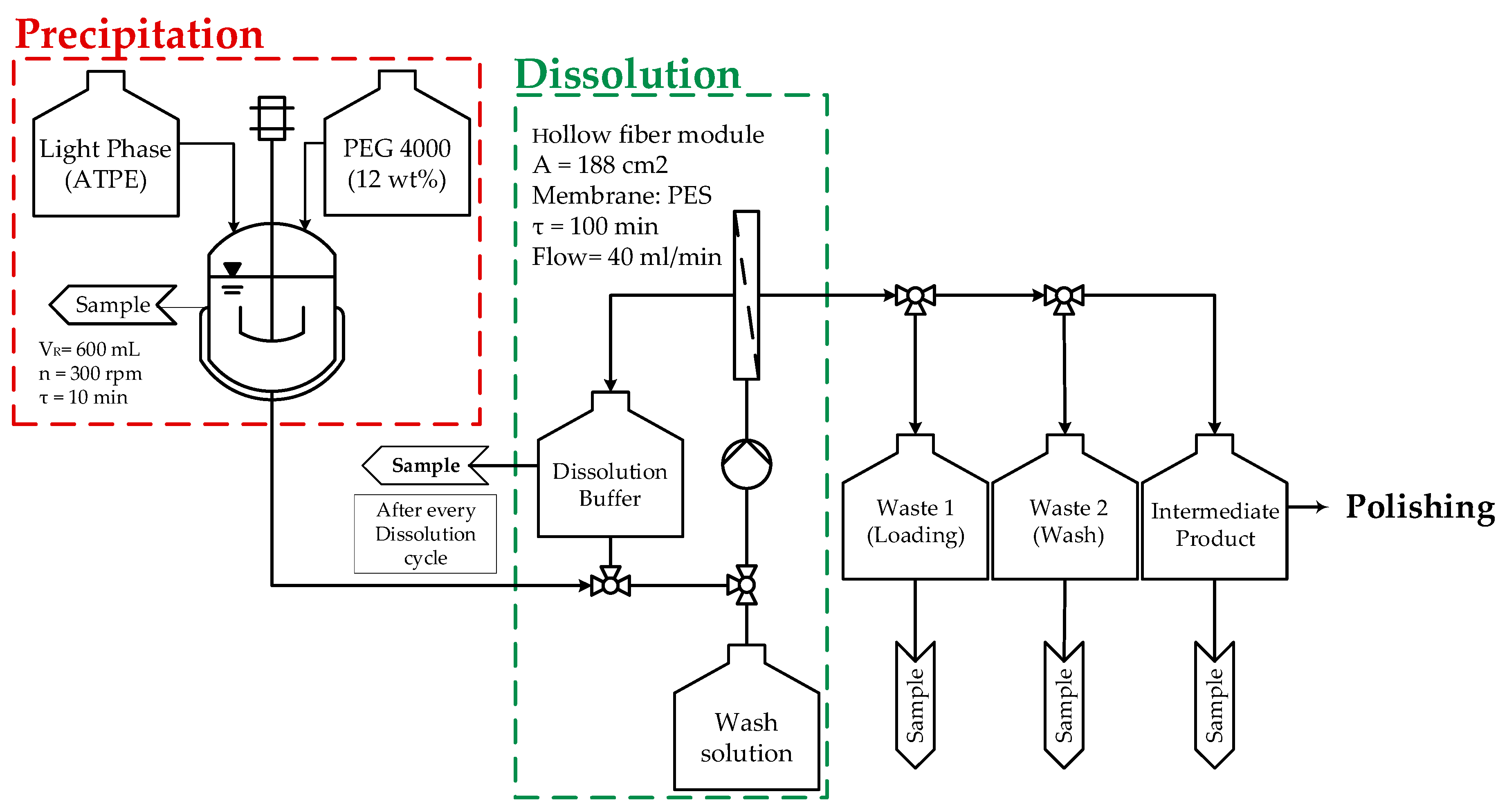
For deeper process comprehension the procedure as well as the flow chart are presented shortly. The procedure of the precipitation unit is segmented into the following steps and is shown in Figure 4 in detail:
- Precipitation of IgG;
- Loading of hollow fiber membrane;
- Precipitate wash;
- Dissolution of the target;
- Filtration (intermediate product).
Hereafter, the defined states: Precipitation, loading, wash, dissolution, and intermediate are used as independent terms for process description. Precipitation takes place in a CSTR (red dashed lines). Followed, by solid–liquid separation of the mixture through a hollow fiber module. Afterwards, the permeate is processed further into a waste tank (waste 1) and, thus, the precipitate dewatered. After loading, superficial impurities are eliminated through a washing step. During this time, the precipitate is still in solid phase and remains onto the inner surface of the fibers (green dashed lines). Fourthly, dissolution is carried out by recycling a suitable buffer alongside the fibers for a certain dwell time. Finally, the recycled buffer, enriched with re-dissolved mAb, is filtrated through the hollow fiber membrane and the intermediate product is obtained. From here onwards, further purification steps are performed. Each process step and its process parameters are depicted in Appendix A in Table A2.
Crucial points during operation are the complete and selective precipitation of IgG as well as the dissolution of precipitate. Most important during the unit operation is that the mAb retains its biological activity, which is given by correct retention of the glycosylation [51,52].
Generally speaking, a turbidity probe can be used to monitor precipitation progress as control strategy, but not for IgG precisely. Further, turbidity and conductivity probes can be used to detect progress during dissolution. Due to the fact that precipitation is a data-rich process Raman and ATR-FTIR in combination with partial-least square regression (PLS) as well as NIR and MIR come in consideration for monitoring and controlling a precipitation process.
3. Material and Methods
3.1. Cultivation
The production of an immunoglobulin (IgG) was accomplished through cultivation of Chinese hamster ovary cells (CHO DG44) in a serum-free commercial medium (CellcaCHO Expression Platform, Sartorius Stedim Biotech GmbH, Göttingen, Germany) utilizing a 2 L bioreactor (Biostat® B, Sartorius Stedim Biotech GmbH, Göttingen, Germany). Culture conditions were 36.8 °C, pH = 7.1, 60% pO2, and 433 rpm with a fed-batch operating mode starting after 72 h. Offline viable and total cell concentration were repeatedly determined by using a Neubauer chamber (BRAND GMBH + CO KG, Wertheim, Germany), microscope (Motic BA 310, Motic Deutschland GmbH, Wetzlar, Germany), and trypan blue solution (0.4%, Sigma-Aldrich, St. Louis, MO, USA) as dye for the detection of dead cells. Glucose and lactate were repeatedly measured using a LaboTRACE compact (TRACE Analytics GmbH, Braunschweig, Germany).
3.2. Aqueous Two Phase Extraction (ATPE)
3.3. Precipitation
Precipitation was accomplished after ATPE from light phase (LP) using a PEG 4000 stock solution (40 wt%, pellets, Sigma Aldrich, dissolved in 60 wt% HQ H2O). The light phase of ATPE is a mixture of water, PEG 400, and phosphate, which may influence the subsequent precipitation. To begin with, the light phase (LP) is introduced into the CSTR, with a total volume of 600 mL, and stirred at 300 rpm. Rapid stirring had to be avoided in prevention of foaming due to PEG 400 fraction in LP. Afterwards, to start the precipitation, PEG 4000 stock solution is added until the mixture is adjusted to a final PEG content of 12 wt%, respectively, to the protein in the mixture. Precipitation time was set to 10 min.
Solubility experiments to determine the precipitant most suitable for the operation were carried out in 50 mL Falcons® (VWR®, Darmstadt, Germany).
3.4. Solid–Liquid Separation and Precipitate Wash
Solid–liquid separation is performed using a hollow fiber module with a pore size of 0.2 µm (470 cm2, Midikros, Repligen Corporation, Rancho Dominguez, CA, USA). After loading, the precipitate was purified with an additional washing step utilizing a PEG 4000 solution (12 wt%). Volume of the washing solution is equal to the volume of the feed. During the washing step, precipitates remain in solid phase onto the inner surface of the hollow fibers.
3.5. Dissolution
Dissolution was carried out by recycling a 50 mM, sodium dihydrogen phosphate/disodium phosphate buffer at pH = 5 alongside the fibers. The dissolution buffer coincides with the operating buffer for the following IEX chromatography. The motivation of using this buffer for dissolution is to eliminate the dia/ultrafiltration step for buffer and concentration adjustment in the benchmark process shown in. During dissolution, the buffer volume is recycled 10 times, whereby; Dwell time for dissolution is enlarged while the buffer volume is kept constant. Finally, the recycled buffer, which is enriched with dissolved mAb, is filtrated through the hollow fiber membrane, and passed into a third tank as intermediate product.
For evaluation of the effects of pH-value and ionic strength on dissolution, a DoE with varying dissolution buffers differing in pH-value (pH = 3/5/5, 5/6) and ionic strength (20/30/40/50/100/150 mM) was conducted. A full factorial design was used including a center point (triple determination).
3.6. Screening of Washing Solutions
Experiments were carried out in 50 mL Falcons® (VWR®, Darmstadt, Germany). Light phase and PEG 4000 stock solution are mixed until PEG 4000 reaches a fraction of 12 wt%, respective to the protein content. Precipitation is conducted for 10 min and then centrifuged for 5 min by 1000 rpm. Solid–liquid separation is done gently to prevent tight agglomerate formation due to obviate dissolution difficulties. Dissolution was carried out with a sodium dihydrogen phosphate/ disodium phosphate buffer (pH = 5; 50 mM).
3.7. Analytics
The monoclonal antibody was quantified by Protein A chromatography (PA ID Sensor Cartridge, Applied Biosystems, Bedford, MA, USA). Dulbecco’s PBS buffer (Sigma-Aldrich, St. Louis, MO, USA) was used as loading buffer at pH 7.4 and as elution buffer at pH 2.6. The size exclusion chromatography (SEC) was done by using a Yarra™ 3 µm SEC 3000 column (Phenomenex Ltd., Aschaffenburg, Germany) with 0.1 M Na2SO4, 0.05 M Na2HPO4, and 0.05 M NaH2PO4 (Merck KGaA, Darmstadt, Germany) as a buffer system. The absorbance for both methods was monitored at 280 nm.
4. Results
First, the results of the conducted FMEA segmented in precipitation and dissolution are presented. All investigated parameters are assessed in the groups with no, low, medium, and high influence and the results are shown in Table A3. Following, characterizations studies were accomplished to deepen process comprehension and create a scientific foundation for further process model development.
4.1. Results Risk Assessment: Precipitation
To begin with the influencing factors on precipitation like temperature, selection of precipitant as well as mixing time are presented. Subsequently, the results of the influencing factors on dissolution are shown. Thereby, ionic strength, pH value, effect of precipitate wash, buffer volume for dissolution, and quantity of dissolution cycles are evaluated.
4.1.1. Temperature
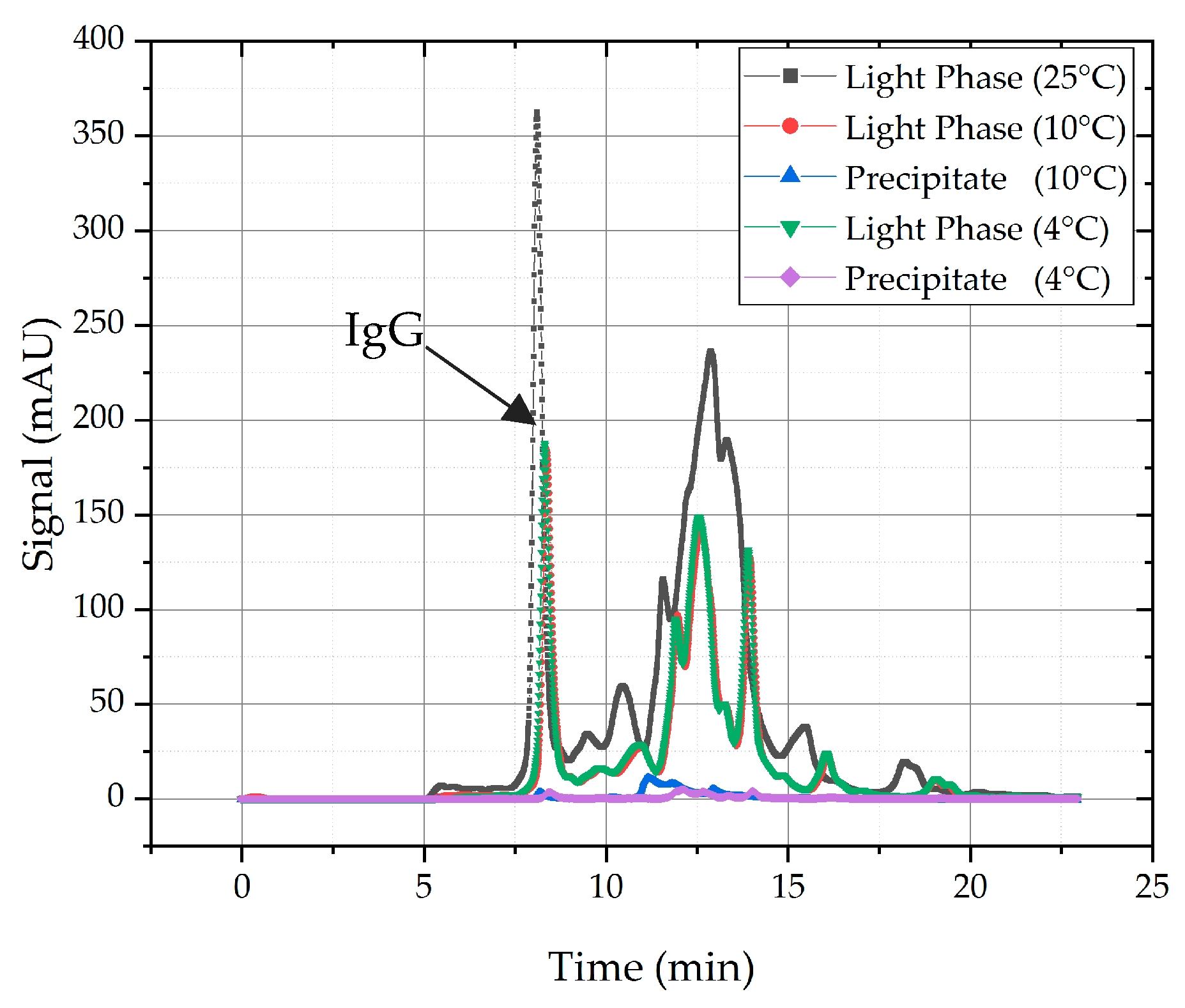
In general, temperature has an effect on precipitation, due to a decrease of solubility of proteins while temperature reduction occurs. This is common knowledge in crystallization. In the context of process development using a QbD approach and the evaluation of all influencing factors in relation to purity and recovery, there is a shift in apprehension. This becomes more comprehensive in Figure 5, where the light phase is depicted at 25 °C as reference (grey line) and the same light phase at 10 °C (red line) as well as at 4 °C (green line). As one can see, precipitation occurred at both temperatures and the precipitated proteins are more or less similar because the chromatograms are almost alike. Both target and side components precipitated because of the temperature shift. The ratio of precipitated HCPs and target component is approximately equal, which leads to the conclusion that temperature has a general effect on solubility of proteins, but it is not selective enough for quality adjustment. In a second step, the feasibility of dissolution of the precipitated proteins was tested (blue and purple line). Analytics showed that dissolution of precipitated proteins are very poor. Because of the reasons mentioned above, temperature is not further investigated in this study as an auxiliary to promote precipitation.
4.1.2. Mixing Time
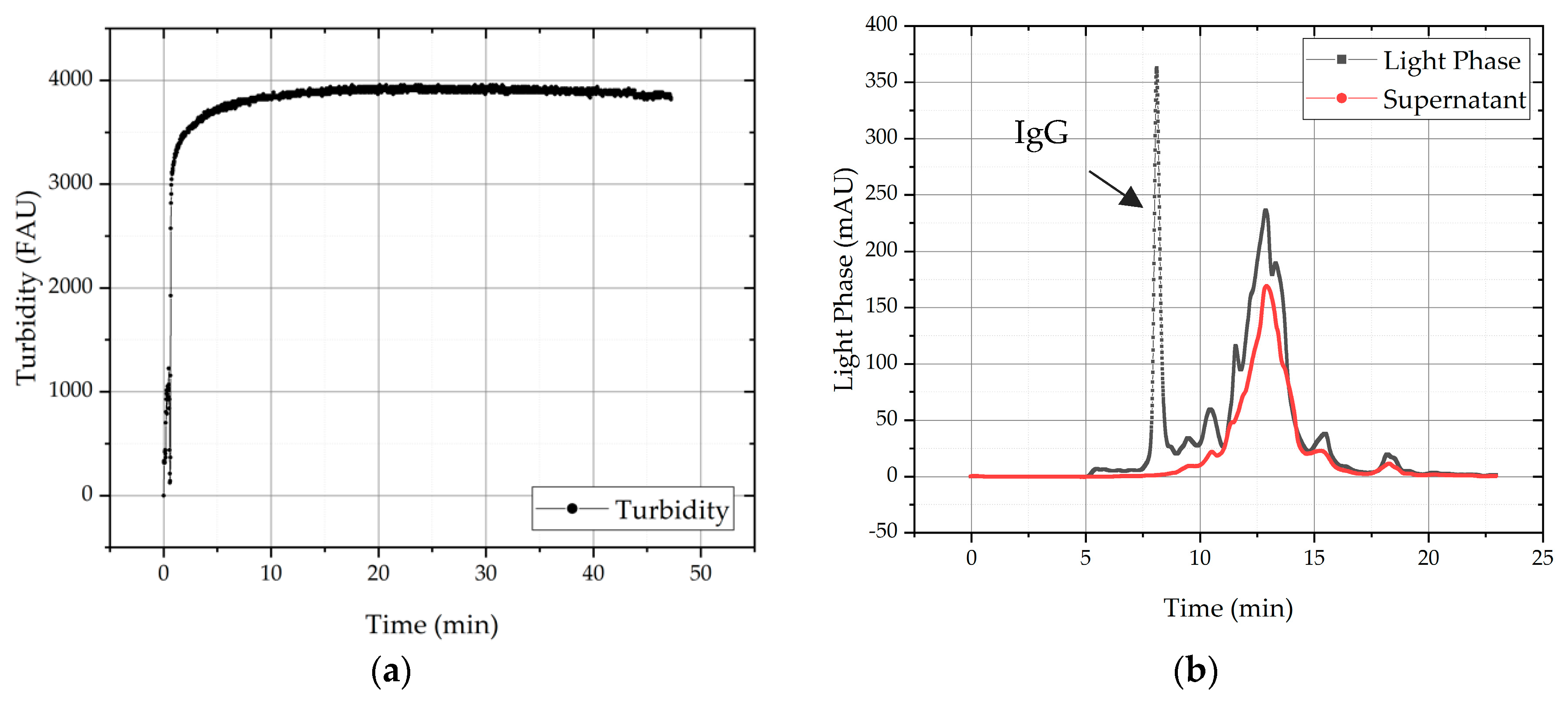
Mixing time was determined by using a turbidity probe during precipitation and is depicted in Figure 6. Due to the strong slope in the beginning, it can be concluded that most of the precipitation process happens immediately. It can also be seen that the turbidity signal is almost constant level after 10 min, which leads to the assumption that precipitation of all insoluble proteins is completed after that time. To evaluate the precipitation and its selectivity samples were analyzed with SEC. The chromatogram of the feed solution, here light phase conducted through ATPE, is shown as starting point (grey line) for separation task as well as the chromatogram of the supernatant after precipitation (red line). The analysis of the supernatant after 10 min shows that no IgG and mostly HCPs remain in the supernatant. In implication, it can be said that 100% of mAb must be precipitated.
Therefore, dwell time for all subsequent experiments is set to 10 min mixing and precipitation time. Usually, stirring and mixing effects are crucial for crystallization, because the process itself is a lot slower than precipitation. Nonetheless, stirring rate varied between 200 and 400 rpm to evaluate associated mixing effects. Even with varying numbers of revolutions, no differences in turbidity signal could be seen, therefore stirring rate and mixing effects are not further considered in this study.
4.1.3. Precipitant
The precipitant has a major influence on product quality and purity. In this study, PEGs with molecular weights of 1450, 4000, 6000, 8000, and 12,000 were tested. Due to prior knowledge, PEG 4000 and PEG 6000 are suitable for IgG precipitation. For our system solubility, curves of the IgG were conducted, but using fermentation broth to evaluate whether behavior of precipitation with varying PEGs is different compared to precipitation of IgG out of a solution with IgG only. Further, behavior of precipitation directly from light phase were conducted to evaluate the influence of PEG 400 and salt fraction in light phase on precipitation. In Figure 7, the solubility curve of IgG precipitated out of light (left) as well as the reduction of HCPs with increasing PEG concentrations are displayed. It can be seen that, with increasing molecular weight of PEG, the solubility of proteins decreased drastically. PEGs with molecular weight of 4000 and higher show a similar precipitation effectiveness and result in complete precipitation of IgG at a PEG weight percentage of 9. Compared to other works, PEG 4000 content is needed for lower complete precipitation [28,31], but can be explained by additional effect of excluded volume and attractive depletion caused by PEG 400 fraction in LP. Moreover, the solubility of undesired HCPs was examined and ascertained that ≥75% of HCPs stay in solution until a molecular weight of PEG 8000 inclusively. The effects of excluded volume and attractive depletion predominate in PEG 12,000 with the result that smaller proteins also co-precipitate alongside with the target component. In contrast, PEG 1450 shows the best solubility for HCPs, but a lot higher PEG fraction is needed for complete precipitation than for PEG 4000. Moreover, the final content of PEG has to be minimized. Therefore, PEG 4000 was chosen for precipitation because it was similarly effective as PEGs with a higher molecular weight while keeping more HCPs in solution.
4.1.4. Precipitate Wash
Precipitate wash was conducted to eliminate superficial impurities and enhance purity of the intermediate product. As washing solution, a buffer is needed that supplies minimal solubility for the precipitated mAb to ensure that IgG stays in its agglomerated form and only impurities are washed away from the surface. Therefore, a saturated ammonium sulfate as well as a sodium sulfate were applied as washing solution. Both are widely used in sample preparation and are predestinated for precipitation of proteins. Further, a HEPES buffer (4-(2-hydroxyethyl)-1-piperazineethanesulfonic acid, 50 mM) at pH = 7 was used because it showed promising results in works of Li et al. [12]. Finally, PEG 4000 (12 wt%), which was utilized as precipitation agent, was also tested as washing solution.
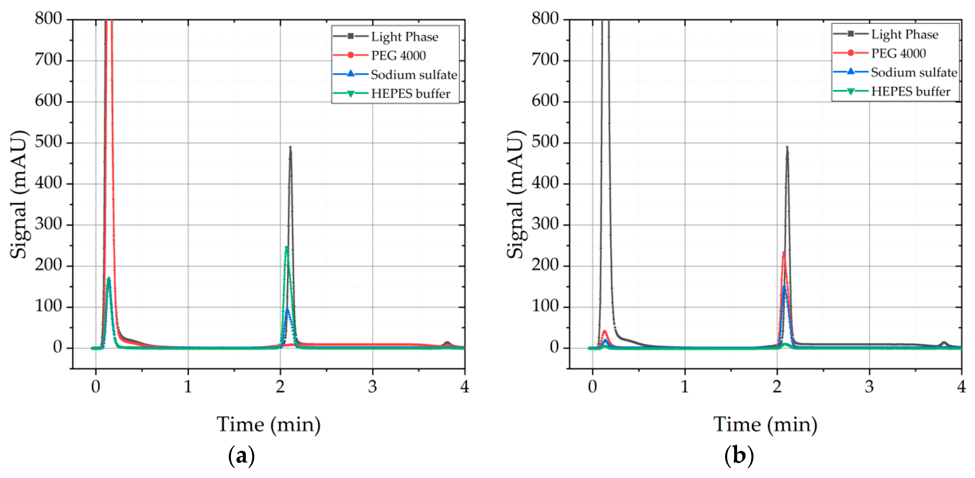
Washing with ammonium sulfate was not feasible due to intense flocculation, which could not be re-dissolved; therefore, analytics were aggravated. In Figure 8, the results of the three other wash solutions are depicted. On the left side, the SEC-chromatogram of the waste after washing is displayed. It can be seen that in the case of sodium sulfate solution and HEPES buffer, mAb is found in the supernatant after washing which is highly undesirable. Therefore, both solutions are not suitable as washing solutions for mAb precipitates due to yield loss. In contrast, PEG 4000 solution has a very poor solubility for IgG, therefore no IgG is found in the supernatant after washing. On the right side, the SEC-Chromatogram of the supernatant after dissolution is displayed.
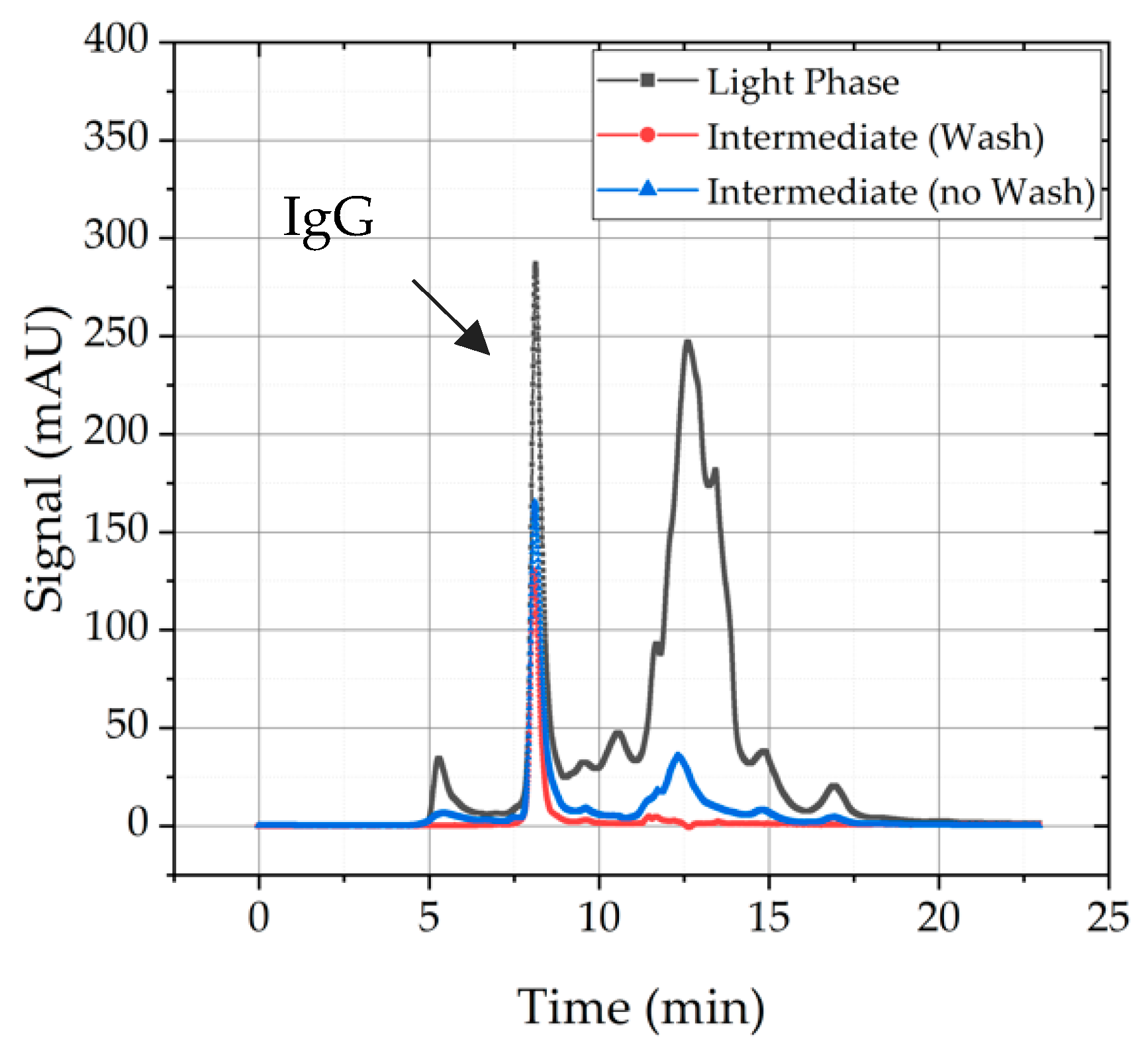
Nevertheless, a washing step after solid–liquid separation is reasonable because superficial purities are washed away and product purity is enhanced, which can be seen in Figure 9. Light phase serves as starting point and gives an indication how many HCPs have to be eliminated and whether mAb recovery was successful or not. It becomes obvious that the experiment without a precipitate wash (blue line) exhibits more HCPs than the intermediate product treated with a precipitate wash. Furthermore, recovery of both procedures is comparable. Therefore, a washing step is included in standard precipitation process.
4.2. Results Risk Assessment: Dissolution
In this section, the results of the FMEA dealing with the dissolution of precipitates are presented. As already mentioned, the approach to the result in complete dissolution is to think reversely to precipitation. Every effort that was made to make sure that the most full precipitation possible can be applied reversely.
4.2.1. Ionic Strength and pH-Value
The effects of ionic strength and pH value on mAb recovery and purity are evaluated through a DoE that is accomplished with distinct dissolution buffers (varying pH and ionic strength). The statistical analysis of the data obtained from the DoE is done by using JMP® software (SAS). For this purpose, a model is adapted, which can be used in the further course for the prediction of onward experimental point. The model accuracy is given by R2, which lies between zero and one and should be close to one for a good prognosis. In addition, the p-value indicates how reliable the data described by the model is and whether it is in the range of the significance level. The significance level here is defined to p = 0.05.
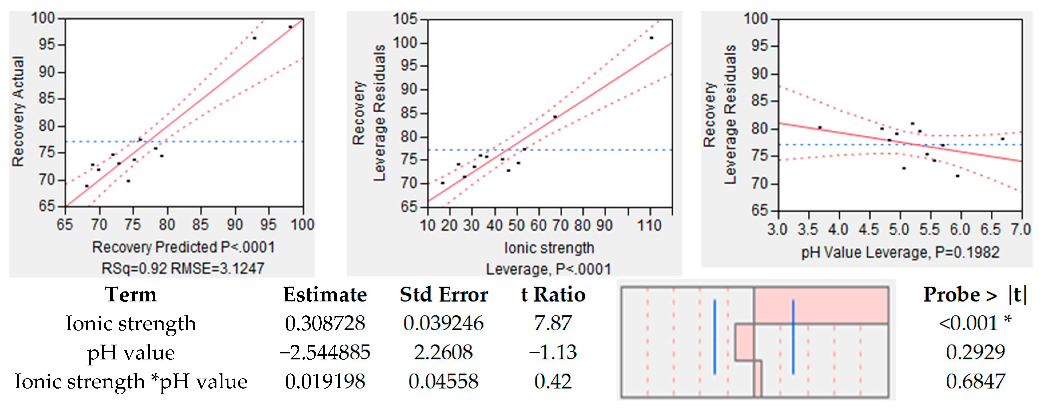
In the case of recovery, results of the statistical analysis are shown in Figure 10. On the left side, the actual recovery is plotted over the predicted recovery. It can be seen that the model is capable of a veridical prediction due to a R2 = 0.92 and a p-value of 0.0001. The effect tests have shown that the model accuracy is due to the ionic strength (center), since the pH has no significant effect on the yield of the antibody. This is expressed by the p-value of 0.1982.
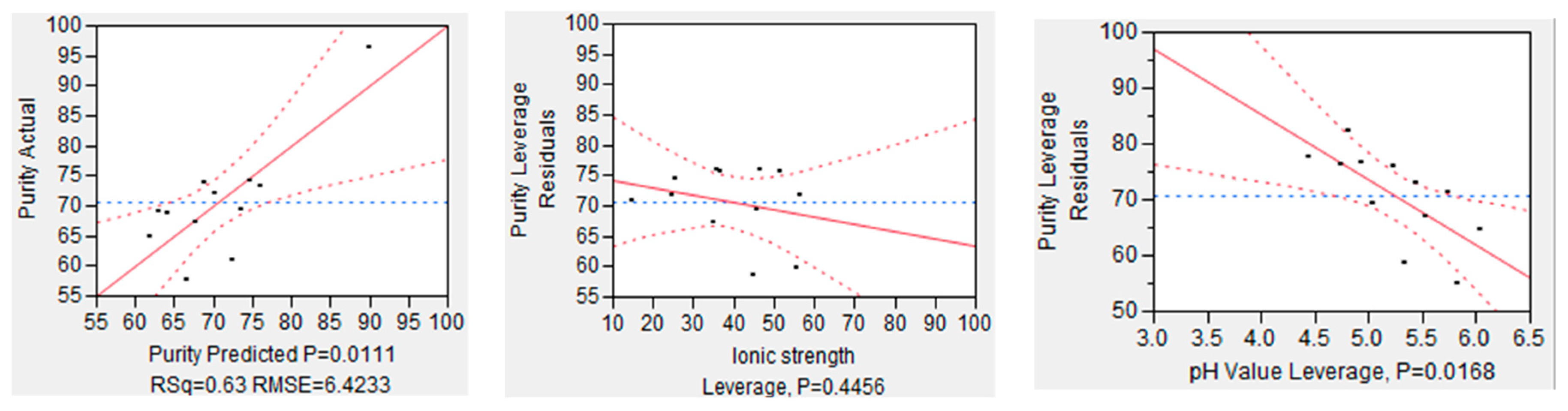
The same analysis was conducted for purity, which is depicted in Figure 11. On the left side, the overall model accuracy is shown, which is less precise as the one for recovery. The accuracy for the prediction model of purity is R2 = 0.63 with a significance level of p value of 0.0111. In this case, the pH value has a significant effect on the model quality because of p value below the significance level (p = 0.00168). However, the ionic strength seems to have, statistically, no influence on mAb purity due to a p value of 0.4456. All in all, it can be said that the recovery is strongly dependent on the employed buffer, and ionic strength and pH value support either recovery or purity.
4.2.2. Determination of PEG Content
One of the critical parameters, determined in the risk assessment, is the PEG content remaining in the intermediate product. Therefore, a method to investigate this parameter is necessary. With ATR-FTIR spectroscopy, a fingerprint scope of PEG (900–1600 nm) can be detected. The fingerprint scope of IgG lies between 1600 and 1700 nm but is overlaid by the characteristic peak of water. Nevertheless, IgG can be visualized by the second derivation of the FTIR spectrum [28]. In this way, ATR-FTIR can be used to determine the PEG content and is feasible to give a rapid statement about the structure of IgG after precipitation and the retention of its biological activity.
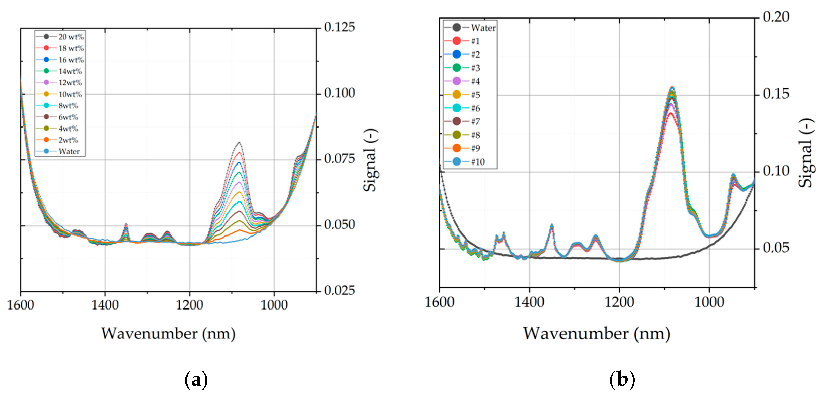
One challenge of this analytical method is that FTIR spectra are a data-rich source, which need to be simplified. In this context, partial-least-square regression (PLS) is used to extract more information from spectral data and evaluate it in relation to principal components. The PLS-model is built with calibration sets of PEG 400 and PEG 4000. Subsequently, the model was validated with a validation set containing different aqueous mixtures of PEG 400 and PEG 4000 to enhance the model consistency. PEG 400 was analyzed due to the fact that the light phase from ATPE contains about 20 wt% of PEG 400. This might be a possible contaminate in the intermediate product, which affects the solubility of mAb. In Figure 12, two of the dilution sets are shown, which were used for model calibration. On the left, a training set with varying concentrations of PEG 4000 is depicted in the fingerprint scope of PEG. Similar training sets were also conducted for PEG 400 (data not shown). On the right side, a validation set is shown, which contains a mixture of PEG 400 (increasing content from 2 to 20 wt%) and PEG 4000 (decreasing content from 20 to 2 wt%). It can be seen that the spectral data of mixtures with PEG 400 and PEG 4000 are very similar on first sight. The aim of this model is to predict and distinct PEG fractions in the intermediate product after precipitation.
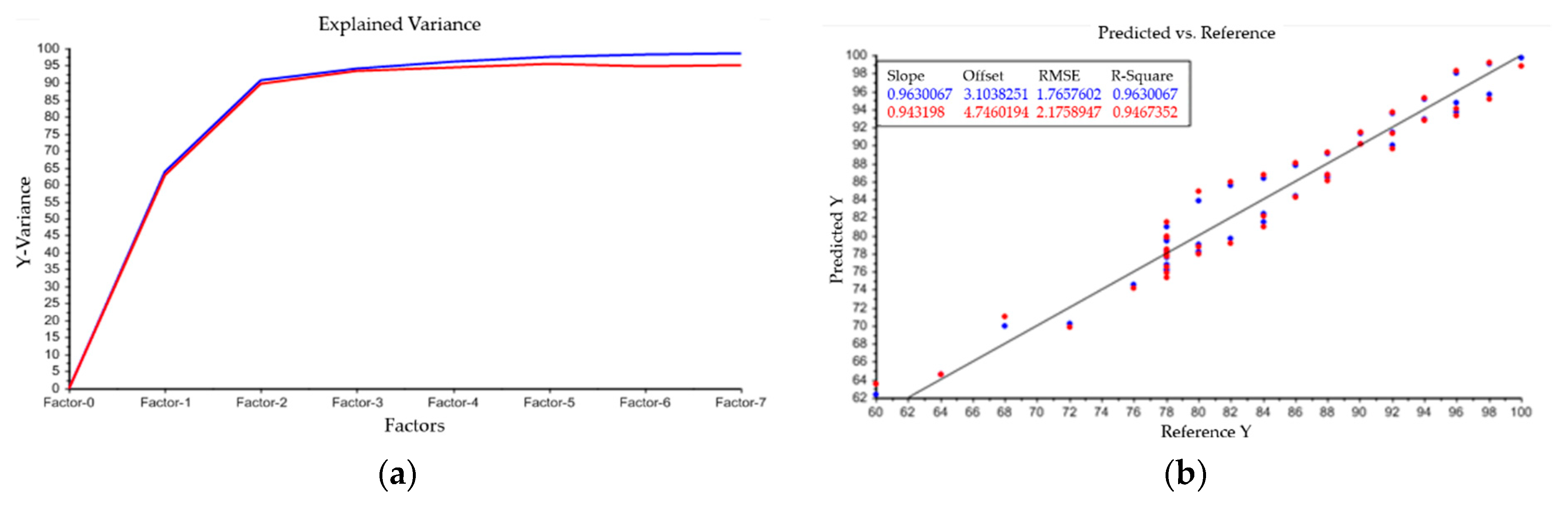
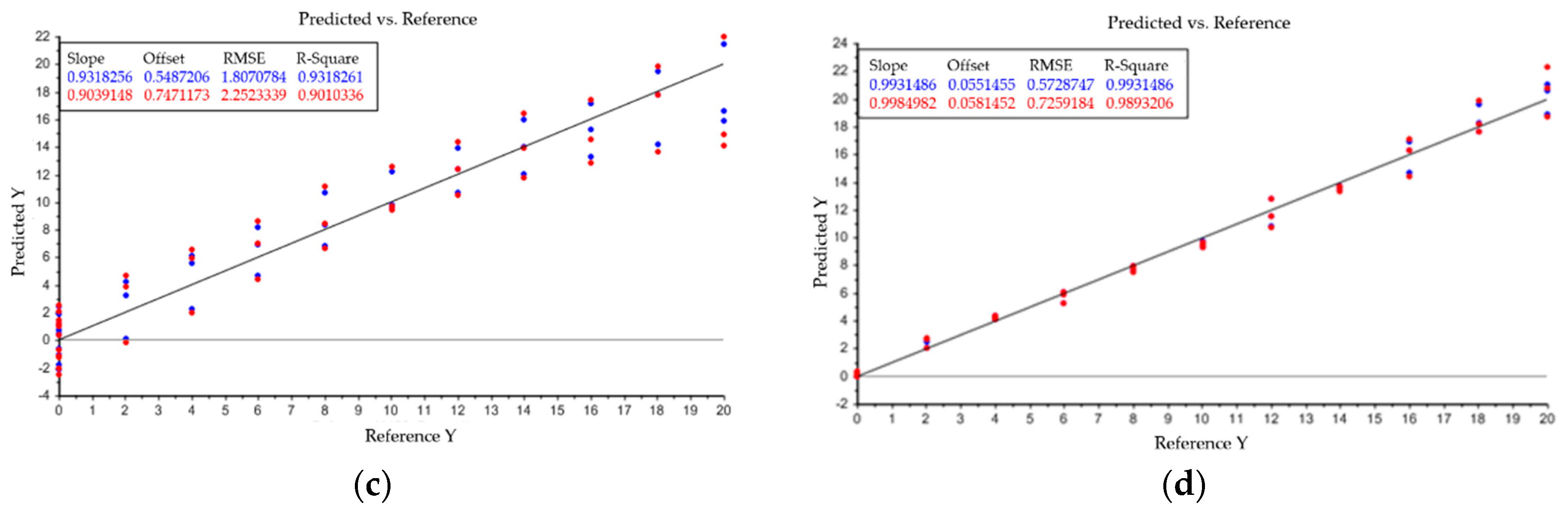
As described above, PLS condenses data points to principle components, which are also described as factors. The goal is to represent the totality of the all data points with as few factors as possible. Therefore, the model uses the explained variance to indicate how many factors are necessary to represent the entirety of the data points. This is depicted in Figure A1 in Appendix A. The blue line is the explained variance of the model within the calibration set and the red line depicts its validation. In this case, three factors are enough to describe the evaluated data. Linear combinations of water, PEG 4000, and PEG 400 and their accuracy, given by R-square, are also shown in Model output: (a) describes the relation between principle components and variance of spectral data. Plots (b–d) indicate the model accuracy of predicted vs. reference data for the three investigated components water (b), PEG 4000 (c) and PEG 400 (d). PEG 400 exhibits the best accuracy between predicted and reference data with a R2 = 0.993. Results for water (R2 = 0.963) and PEG 4000 (R2 = 0.931) are also reasonable. With the presented model, it is possible to predict the content of water, PEG 400, and PEG 4000 separately. Analysis of the intermediate product after precipitation and dissolution resulted in remaining PEG 4000 content of 2–5 wt%. Results were also verified with SEC chromatography. PEG 400 could not be detected and, therefore, is not harmful for further purification steps.
4.2.3. Dissolution Cycles and Recovery
One dissolution cycle means a full circulation of buffer in the experimental set up. The amount of cycles varied to get an indication about resolution of mAb precipitates and its kinetics. Samples have been taken after every dissolution cycle and are plotted as a time curve in Figure 13. It can be seen that during the first three cycles, which means a dwell time of approximately 20 min, most of the dissolution is already terminated. This can be explained by the high concentration gradient at the beginning. Afterwards, dissolution stagnates and the thermodynamic equilibrium is reached. In chapter 0, it was already mentioned that the remaining PEG content is crucial for following unit operations. Additionally, it is also important for determining mAb recovery. It was ascertained that with the described precipitation procedure, a remaining content between 2–5 wt% of PEG is reached. Looking at the solubility curve in Figure 7, it can be seen that the thermodynamic equilibrium for this PEG fraction lies at 50%–95% of mAb recovery. Therefore, dissolution ratio was varied, and the results are depicted in Figure 13 also.
The dissolution behavior has been studied in various experiments during this survey and showed the same course multiple times. For this reason, the full dissolution curve has not been recorded for the dissolution buffer ratio, but rather only the equilibrium value at the end has been determined (Figure 13). With an increasing amount of dissolution buffer, the PEG content is reduced and as a consequence of this, thermodynamic equilibrium is shifted to almost 100% recovery. Due to the fact that the utilized dissolution buffer (50 mM, Sodium phosphate buffer at pH = 5) is simultaneously the operating buffer for the following IEX, volume can be easily reduced by a subsequent diafiltration step. Based on the size distinction between PEG 4000 and IgG (150 kDa), volume reduction in diafiltration should proceed without precipitation issues. Most yield issues in the diafiltration have been caused due to the buffer exchange, not the volume reduction.
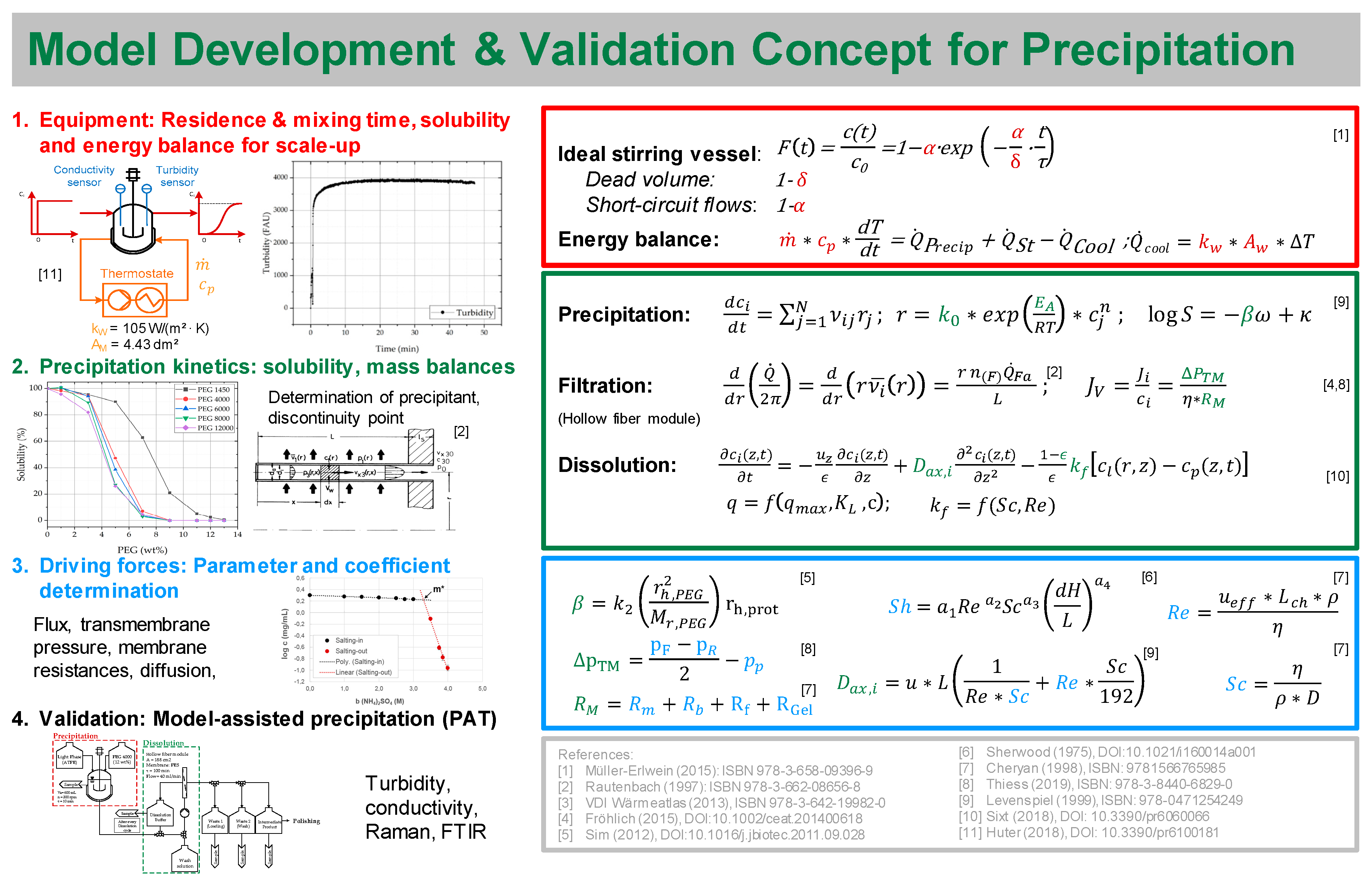
5. Modeling of Precipitation
In the present work, an experimental QbD approach was presented, which allows conclusions about the effort of the process development by means of DoE. An alternative way to conduct the QbD approach would be to support process development by generating a suitable process model for the unit operation precipitation and thereby reduce the experimental overhead to find the optimal operating space. Furthermore, operating parameters can be tested that cannot be implemented in experiments under normal conditions due to the hazard potential. This in turn leads to a deeper understanding of the process and prepares for unwanted incidents. Due to the fact that the use of models is still sparse because of validation, Sixt et al. established a workflow that ensures the development of valid physico-chemical models [49]. This has already been described in various papers and the execution was shown using the example of liquid–liquid [55] and solid–liquid extraction [49], chromatography [56], and cultivation [57].
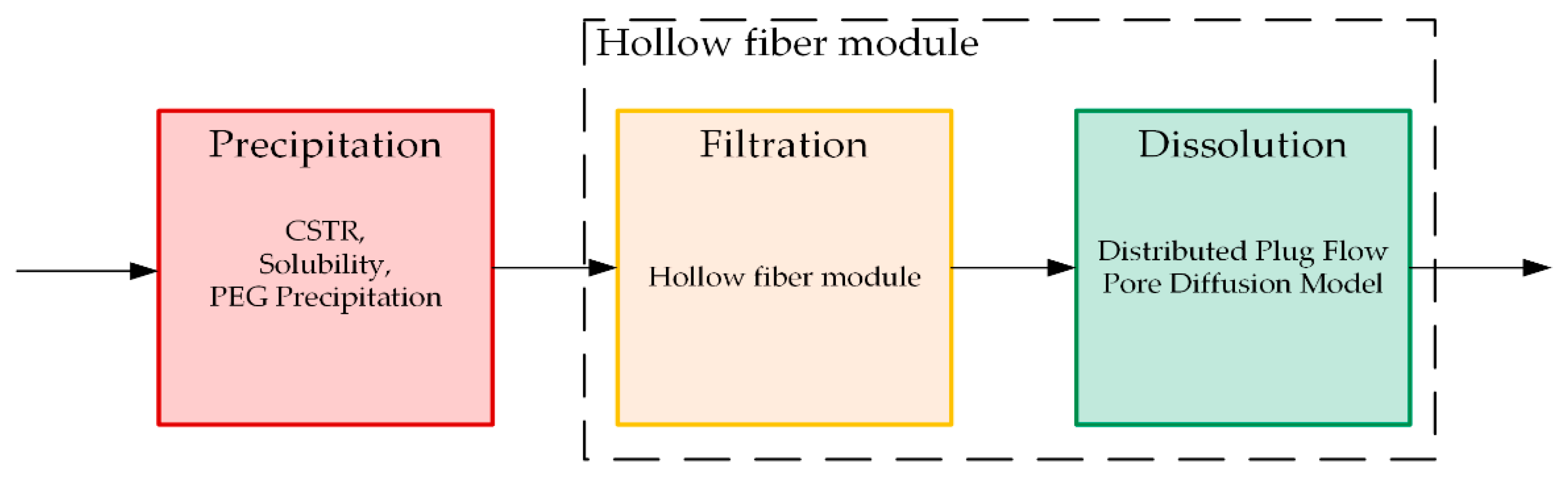
The process described above consists of three different parts that have to be distinguished for model building: Precipitation, filtration, and dissolution (Figure 14). For each subarea, a separate model must be set up before it can be linked to a rigorous physico-chemical process model. Thereby, the model must be able to predict filterability as a function of filter surface area, pressure drop, permeate flux, and viscosity, as well as mAb concentration of the feed. Further, yield and purity must be included as a function of ionic strength, pH value, PEG content, and dissolution ratio.
Thus far, no process model has been described in literature for the total process of precipitation. Nevertheless, the following model approaches have been made for precipitation. To begin with, correlations describing equilibrium and solubility of proteins have been found [40,58] and extended for the change in solubility in presence of PEG molecules [32,34,36,59]. Further, empirical models like quantitative structure–activity relationship (QSAR) are applied to predict the discontinuity point of proteins in presence of PEG molecules [35,36]. Moreover, model approaches derived from a mechanistic model approach for crystallization are described also for precipitation [60,61,62,63,64,65]. These models are built with population balances and contain detailed information about nucleation, birth, growth, and disruption of crystals or agglomerates. This becomes indeed vital for crystallization processes because shape and size distributions are important information during operation. In the case of precipitation, this becomes less important because the precipitates itself are not the final product. Precipitation is just a temporary state and, therefore, population balances compromise non-essential information. Additionally, a mechanistic model approach for the precipitation curve was presented by Großhans et al. [43].
Previous work has already presented a general model development and validation concept, which can be used to construct physico-chemical models of unit operations [66,67,68,69,70,71,72]. The described process is broken down into the individual building blocks and described with physical principles and laws. The first part covers the equipment and the fluid dynamics to enable a scale-up of the system later on. Here, the residence time, mixing time, and energy balance are taken into account. The second step describes the kinetics of the process itself, which are underpinned by mass balances separately for precipitation, filtration, and dissolution. The model for precipitation is based on a reactive decrease of antibody concentration in the supernatant. This is further combined with solubility of IgG in presence of PEG [32]. Because precipitates remain in the filter, the geometry of the hollow fiber module has to be considered for the models of filtration and dissolution. For filtration with hollow fibers, various modeling approaches exist in the literature [73,74,75]. The model for dissolution is based on a distributed plug flow approach (DPF) linked with a pore diffusion model obtained from solid–liquid extraction [49]. Based on this, missing parameters and coefficients are determined, which adapt the model to the respective material system. Subsequently, the model is validated by conducting selected experiments under application of process analytical technology. In this way, the model can be adjusted quickly to different material systems. The general overview of the procedure is shown for the unit operation precipitation (Figure 15).
6. Conclusions
In this work, a DoE-based QbD approach has been presented for integration of precipitation in biologics manufacturing. The studies were conducted using the example of monoclonal antibodies and the precipitation of the target component IgG. With the accomplished DoE, a design space was found and evaluated in relation to mAb recovery and purity. It became obvious that precipitation with PEG 4000 with a weight percentage of 12 respective to protein is most suitable for complete precipitation. Moreover, a sodium phosphate buffer at a pH value of five and an ionic strength of 50 mM is convenient for sufficient dissolution. Thereby, a dissolution ratio between 1:4 and 1:8 leads to satisfying recoveries ≥ 95%.
Unit operations form the building blocks of each industrial process. As shown, the experimental based process development is a time-consuming and expensive process, which needs to be redone as soon as the material system differs. In order to optimize process development for novel products, a model-based implementation approach can be used to support a resource efficient establishment.
It was discussed which requirements a process model must meet to obtain a valid rigorous physico-chemical model. The model should be capable of predicting filterability as a function of filter surface area, pressure drop, permeate flux, as well as viscosity. Further, yield and purity must be included as a function of ionic strength, pH value, PEG content, and dissolution ratio. Thus, a development and validation concept was presented, which has already been successfully implemented for model building of valid physico-chemical models for other unit operations [49,55,56,66,72]. Due to the fact that the model is based on physical principals and laws, less experimental effort for parameter determination is necessary to transfer the model to novel material systems. Future works will focus on the transfer to new product platforms like antibody fragments, VLPs and exosomes.
Author Contributions
L.J.L. conceived, designed, and performed the experiments as well as wrote the paper. All authors interpreted the data. J.S. substantively revised the work and contributed the materials and analysis tools. J.S. is responsible for conception and supervision. All authors have read and agreed to the published version of the manuscript.
Funding
This research received funding from BMWi project “Traceless Plant Traceless Production”.
Acknowledgments
The authors would like to acknowledge their institute’s laboratory colleagues, especially Frank Steinhäuser and Volker Strohmeyer as well as Thomas Knebel. In addition, the authors would like to thank BMWI, especially Gahr, for project funding “Traceless Plant Traceless Production” and the whole TPTP consortium. The authors would also like to thank Axel Schmidt for his support with ATPE, equilibrium and solubility determination, Lukas Uhlenbrock for his QbD expertise, Florian Vetter for productive discussions as well as Mourad Mouellef for his support with multivariate data analysis. Special thanks are addressed to Larissa Knierim for her excellent laboratory work.
Conflicts of Interest
The others declare no conflict of interest.
Appendix A

Table A1.
Risk Assessment: Failure- mode-effect-analysis (FMEA). Foundation for conducted DoE.
| Severity (S) | Occurrence (O) | Detection (D) | Criticality (SxO) | RPN (SxOxD) | Comment | |
|---|---|---|---|---|---|---|
| Target Component | 10 | 9 | 9 | 90 | 810 | Is expected to be in good control, once characterized in feed. However, detection is offline and cannot be monitored during process. Must be controlled to avoid yield loss. Parameters: recovery and purity |
| Side Component | 9 | 9 | 9 | 81 | 729 | Is expected to be in good control, once characterized in feed. However, detection is offline and cannot be monitored during process. Must be controlled to avoid ineffectiveness and underperformance of unit. Parameters: purity |
| Precipitation | 9 | 6 | 9 | 54 | 486 | Scope of precipitation => complete/incomplete. Must be controlled for effective precipitation and to avoid yield loss. Precipitation of target component demands that biological activity is retained. |
| Precipitant | 8 | 6 | 10 | 48 | 480 | Suitable precipitant for selective precipitation. Might be harmful for following purification step. Precipitant and protein ratio is essential for complete precipitation. Difficulties by detecting correct ratio. |
| Precipitate/Particles | 6 | 5 | 10 | 30 | 300 | Shape of precipitates is not crucial for the product after the unit, because it is a temporary state. It might influence dissolution and be harmful to filters. Detection of shape during process is difficult. |
| Temperature | 8 | 8 | 2 | 64 | 128 | Is expected to be in good control, once temperature range is characterized. Temperature shifts lead to crystallization/precipitation and can effect purity of the target. Temperature can be detected easily. |
| Mixing | 8 | 6 | 9 | 48 | 432 | Mixing is essential for precipitation. Complete and selective precipitation occurs due to the correct ratio of precipitant and protein. Mixing state is difficult to detect and influences scope of precipitation. It has to be considered particularly in large scale. Parameters: stirring rate, mixing time, vessel volume. |
| Filtration | 9 | 5 | 1 | 45 | 45 | Filtration is a function of flux, mAb concentration and pressure. In small scale less important. Has to be considered in Up-Scale. |
| Dissolution | 10 | 9 | 8 | 90 | 720 | Dissolution is essential for recovery of product and leads to high yield loss and ineffectiveness of the unit. Parameters: selectivity, capacity, dissolution buffer ratio and dwell time. |
Table A2.
Overview of operating procedure for deeper process comprehension.
| Process Step | Flow Chart |
|---|---|
| Precipitation: Precipitant: PEG 4000 (12 wt%) VR = 600 mL τ = 10 min n = 300 rpm |  |
| Loading: Hollow fiber module is used for solid-liquid separation Pore size: 0.2 µm A = 470 cm2 P = 250 mbar Membrane: Polyether sulfone (PES) |  |
| Wash: PEG 4000 (12 wt%) is selected as wash solution This amount of PEG 4000 ensures no dissolution of mAb Reduction of surficial HCPs on precipitates |  |
| Dissolution: Dissolution ratio can be adjusted by added volume of dissolution buffer Dissolution ration of 1:1 is desired Buffer volume is recycled 10 times to enlarge dwell time but small dissolution ratio |  |
| Filtration/Intermediate Product Filtration of recycled dissolution buffer through filter module |  |
Table A3.
Results of the conducted DoE and evaluation of effects on product yield and purity.
| Process Parameters | Process Parameter Range | Unit | Purity IgG | Yield IgG | Rationale |
|---|---|---|---|---|---|
| Precipitation | |||||
| Temperature | 4 to 25 | °C | No | No | No impact in this range, thus not include in this study. Precipitation occurs more rapidly by low temperatures but it does not affect purity and yield of mAb. |
| Mixing Time | 1 to 60 | min | Low | Low | Low effect of Precipitation duration; precipitation occurs immediately. |
| Stirring rate | 200 to 400 | rpm | No | No | Less important in small scale, precipitation occurs directly after addition of PEG. Should be taken into account for large scale operation. |
| Precipitant | 1450–12000 | MW | High | High | Screening of different PEGs. Due to prior knowledge PEG 1450 was set as starting point. |
| Precipitant ratio | 10 to 16 | wt% PEG | High | High | No mAb was found in supernatant when precipitant ratio was higher than 12 wt%; below this concentration complete precipitation could not be guaranteed/ensured for PEG 4000. |
| Precipitate Wash | Yes/no | - | Medium | Low | Wash solutions: Ammonium sulfate, Sodium sulfate, PEG 4000, HEPES buffer. Improved Purity due to wash, but low effect on recovery of mAb from precipitate. |
| Dissolution | |||||
| Ionic Strength | 0 to 150 | mM | High | High | Exploitation of salting-in effect. Up to 100 mM addition of salt has a stabilizing effect on proteins in solution, various salts have different effectiveness. |
| pH-Value | 3 to 6 | - | High | High | low pH-Values lead to better dissolution of mAb; simultaneously dissolution of side components might occur. |
| Dissolution volume ratio | 1–16 | - | Medium | Medium | Dissolution volume ratio has a medium impact on dissolution. Yield of dissolution IgG is higher when concentration gradient is greater. |
| Dissolution cycles | 1–10 | - | Medium | Medium | Capacity and concentration gradient is important for dissolution. |
Figure A1.
Model output: (a) describes the relation between principle components and variance of spectral data. Plots (b–d) indicate the model accuracy of predicted vs. reference data for the three investigated components water (b), PEG 4000 (c) and PEG 400 (d).
Figure A1.
Model output: (a) describes the relation between principle components and variance of spectral data. Plots (b–d) indicate the model accuracy of predicted vs. reference data for the three investigated components water (b), PEG 4000 (c) and PEG 400 (d).


References
- BioPharm. The Renaissance of Protein Precipitation. BioPharm Int. 2006, 19, 8. [Google Scholar]
- EvaluatePharma. World Preview 2017: Outlook to 2022. 2017. Available online: www.evaluate.com/PharmaWorldPreview2017 (accessed on 4 September 2019).
- Dos Santos, R.; Carvalho, A.L.; Roque, A.C.A. Renaissance of protein crystallization and precipitation in biopharmaceuticals purification. Biotechnol. Adv. 2017, 35, 41–50. [Google Scholar] [CrossRef] [PubMed]
- Singh, N.; Arunkumar, A.; Chollangi, S.; Tan, Z.G.; Borys, M.; Li, Z.J. Clarification technologies for monoclonal antibody manufacturing processes: Current state and future perspectives. Biotechnol. Bioeng. 2016, 113, 698–716. [Google Scholar] [CrossRef] [PubMed]
- Baumann, P.; Hubbuch, J. Downstream process development strategies for effective bioprocesses: Trends, progress, and combinatorial approaches. Eng. Life Sci. 2017, 17, 1142–1158. [Google Scholar] [CrossRef]
- Cho, B.S.; Kim, J.O.; Ha, D.H.; Yi, Y.W. Exosomes derived from human adipose tissue-derived mesenchymal stem cells alleviate atopic dermatitis. Stem Cell Res. Ther. 2018, 9, 187. [Google Scholar] [CrossRef] [Green Version]
- Fuenmayor, J.; Gòdia, F.; Cervera, L. Production of virus-like particles for vaccines. New Biotechnol. 2017, 39, 174–180. [Google Scholar] [CrossRef]
- Gagnon, P. Technology trends in antibody purification. J. Chromatogr. A 2012, 1221, 57–70. [Google Scholar] [CrossRef] [PubMed]
- Martinez, M.; Spitali, M.; Norrant, E.L.; Bracewell, D.G. Precipitation as an Enabling Technology for the Intensification of Biopharmaceutical Manufacture. Trends Biotechnol. 2019, 37, 237–241. [Google Scholar] [CrossRef] [PubMed] [Green Version]
- Hammerschmidt, N.; Tscheliessnig, A.; Sommer, R.; Helk, B.; Jungbauer, A. Economics of recombinant antibody production processes at various scales: Industry-standard compared to continuous precipitation. Biotechnol. J. 2014, 9, 766–775. [Google Scholar] [CrossRef]
- Burgstaller, D.; Jungbauer, A.; Satzer, P. Continuous integrated antibody precipitation with two-stage tangential flow microfiltration enables constant mass flow. Biotechnol. Bioeng. 2019, 116, 1053–1065. [Google Scholar] [CrossRef] [PubMed] [Green Version]
- Li, Z.; Gu, Q.; Coffman, J.L.; Przybycien, T.; Zydney, A.L. Continuous precipitation for monoclonal antibody capture using countercurrent washing by microfiltration. Biotechnol. Prog. 2019, e2886. [Google Scholar] [CrossRef] [PubMed]
- Hammerschmidt, N.; Hobiger, S.; Jungbauer, A. Continuous polyethylene glycol precipitation of recombinant antibodies: Sequential precipitation and resolubilization. Process Biochem. 2016, 51, 325–332. [Google Scholar] [CrossRef] [Green Version]
- Swartz, A.R.; Xu, X.; Traylor, S.J.; Li, Z.J.; Chen, W. One-step affinity capture and precipitation for improved purification of an industrial monoclonal antibody using Z-ELP functionalized nanocages. Biotechnol. Bioeng. 2018, 115, 423–432. [Google Scholar] [CrossRef] [PubMed]
- Gisela, S.M. The Affinity Precipitat Ion for the Isolat Ion of Biomolecules; EPFL: Lausanne, Switzerland, 2007. [Google Scholar]
- Hilbrig, F.; Freitag, R. Protein purification by affinity precipitation. J. Chromatogr. B 2003, 790, 79–90. [Google Scholar] [CrossRef]
- Scopes, R.K. Protein Purification. Principles and Practice, 3rd ed.; Springer: New York, NY, USA, 1994; ISBN 0387940723. [Google Scholar]
- Chmiel, H. Bioprozesstechnik; 3rd neu bearb. Aufl.; Spektrum Akademischer Verlag: Heidelberg, Germany, 2011. [Google Scholar]
- Kayser, V.; Chennamsetty, N.; Voynov, V.; Forrer, K.; Helk, B.; Trout, B.L. Glycosylation influences on the aggregation propensity of therapeutic monoclonal antibodies. Biotechnol. J. 2011, 6, 38–44. [Google Scholar] [CrossRef] [PubMed]
- Jefferis, R. Glycosylation of recombinant antibody therapeutics. Biotechnol. Prog. 2005, 21, 11–16. [Google Scholar] [CrossRef]
- Raju, T.S. Terminal sugars of Fc glycans influence antibody effector functions of IgGs. Curr. Opin. Immunol. 2008, 20, 471–478. [Google Scholar] [CrossRef]
- Hodoniczky, J.; Zheng, Y.Z.; James, D.C. Control of recombinant monoclonal antibody effector functions by Fc N-glycan remodeling in vitro. Biotechnol. Prog. 2005, 21, 1644–1652. [Google Scholar] [CrossRef]
- Abès, R.; Teillaud, J.-L. Impact of Glycosylation on Effector Functions of Therapeutic IgG. Pharmaceuticals 2010, 3, 146–157. [Google Scholar] [CrossRef]
- Wright, A.; Morrison, S.L. Effect of glycosylation on Effect og glycosylation on antibody function: Implications for genetic engineering. TIBTECH 1997, 15, 26–32. [Google Scholar] [CrossRef]
- del Val, I.J.; Kontoravdi, C.; Nagy, J.M. Towards the implementation of quality by design to the production of therapeutic monoclonal antibodies with desired glycosylation patterns. Biotechnol. Prog. 2010, 26, 1505–1527. [Google Scholar] [CrossRef] [PubMed]
- Atha, D.H.; Ingham, K.C. Mechanism of Precipiation of Proteins by polyethylene Glycols. J. Biochem. Chem. 1981, 256, 12108–12117. [Google Scholar]
- Thompson, R.W.; Latypov, R.F.; Wang, Y.; Lomakin, A.; Meyer, J.A.; Vunnum, S.; Benedek, G.B. Evaluation of effects of pH and ionic strength on colloidal stability of IgG solutions by PEG-induced liquid-liquid phase separation. J. Chem. Phys. 2016, 145, 185101. [Google Scholar] [CrossRef] [PubMed]
- Oelmeier, S.A.; Ladd-Effio, C.; Hubbuch, J. Alternative separation steps for monoclonal antibody purification: Combination of centrifugal partitioning chromatography and precipitation. J. Chromatogr. A 2013, 1319, 118–126. [Google Scholar] [CrossRef]
- Brodsky, Y.; Zhang, C.; Yigzaw, Y.; Vedantham, G. Caprylic acid precipitation method for impurity reduction: An alternative to conventional chromatography for monoclonal antibody purification. Biotechnol. Bioeng. 2012, 109, 2589–2598. [Google Scholar] [CrossRef]
- Christen, P.; Jaussi, R.; Benoit, R. Biochemie und Molekularbiologie; Springer: Berlin/Heidelberg, Germany, 2016. [Google Scholar]
- Großhans, S.; Wang, G.; Fischer, C.; Hubbuch, J. An integrated precipitation and ion-exchange chromatography process for antibody manufacturing: Process development strategy and continuous chromatography exploration. J. Chromatogr. A 2018, 1533, 66–76. [Google Scholar] [CrossRef]
- Sim, S.-L.; He, T.; Tscheliessnig, A.; Mueller, M.; Tan, R.B.H.; Jungbauer, A. Protein precipitation by polyethylene glycol: A generalized model based on hydrodynamic radius. J. Biotechnol. 2012, 157, 315–319. [Google Scholar] [CrossRef]
- Giese, G.; Myrold, A.; Gorrell, J.; Persson, J. Purification of antibodies by precipitating impurities using Polyethylene Glycol to enable a two chromatography step process. J. Chromatogr. B 2013, 938, 14–21. [Google Scholar] [CrossRef]
- Zhou, Y. Mathematical Modelling of Protein Precipitation Based on the Phase Equilibrium for an Antibody Fragment from E. coli Lysis. J. Bioprocess. Biotech. 2013, 3. [Google Scholar] [CrossRef] [Green Version]
- Bauer, K.C.; Hämmerling, F.; Kittelmann, J.; Dürr, C.; Görlich, F.; Hubbuch, J. Influence of structure properties on protein-protein interactions-QSAR modeling of changes in diffusion coefficients. Biotechnol. Bioeng. 2017, 114, 821–831. [Google Scholar] [CrossRef]
- Hämmerling, F.; Ladd Effio, C.; Andris, S.; Kittelmann, J.; Hubbuch, J. Investigation and prediction of protein precipitation by polyethylene glycol using quantitative structure-activity relationship models. J. Biotechnol. 2017, 241, 87–97. [Google Scholar] [CrossRef] [PubMed]
- Sim, S.-L.; He, T.; Tscheliessnig, A.; Mueller, M.; Tan, R.B.H.; Jungbauer, A. Branched polyethylene glycol for protein precipitation. Biotechnol. Bioeng. 2012, 109, 736–746. [Google Scholar] [CrossRef] [PubMed]
- Asakura, S.; Oosawa, F. Interaction between particles suspended in solutions of macromolecules. J. Polym. Sci. 1958, 33, 183–192. [Google Scholar] [CrossRef]
- Iverius, P.H.; Laurent, T.C. Precipitation of some plasma proteins by the addition of dextran or polyethylene glycol. Biochim. Biophys. Acta (BBA) Protein Struct. 1967, 133, 371–373. [Google Scholar] [CrossRef]
- Cohn, E.J.; Strong, L.E. Preparation and properties of serum and plasma proteins; a system for the separation into fractions of the protein and lipoprotein components of biological tissues and fluids. J. Am. Chem. Soc. 1946, 68, 459–475. [Google Scholar] [CrossRef]
- Glynn, J. Process-Scale Precipitation of Impurities in mammalian Cell Culture Broth. In Process Scale Purification of Antibodies; John Wiley & Sons: Hoboken, NJ, USA, 2009; pp. 309–324. [Google Scholar]
- Wang, G. Advancing Downstream Process Development—Mechanistic Modeling and Artificial Intelligence. Available online: https://d-nb.info/1163320358/34 (accessed on 7 January 2020).
- Großhans, S.; Wang, G.; Hubbuch, J. Water on hydrophobic surfaces: Mechanistic modeling of polyethylene glycol-induced protein precipitation. Bioprocess Biosyst. Eng. 2019, 42, 513–520. [Google Scholar] [CrossRef] [Green Version]
- Yu, L.X.; Amidon, G.; Khan, M.A.; Hoag, S.W.; Polli, J.; Raju, G.K.; Woodcock, J. Understanding pharmaceutical quality by design. AAPS J. 2014, 16, 771–783. [Google Scholar] [CrossRef] [Green Version]
- Thakor, N.S.; Amrutkar, S.V. Implementing Quality by Design (QbD) in Chromatography: Review Article. Austin J. Anal. Pharm. Chem. 2017, 4, 1–5. [Google Scholar]
- EMA-FDA. EMA-FDA Pilot Program for Parallel Assessment of Quality-by-Design Applications: Lessons Learnt and Q&A Resulting from the First Parallel Assessment; FDA: Silver Spring, MD, USA, 2013.
- FDA. Guidance for Industry: Q9 Quality Risk Management; FDA: Silver Spring, MD, USA, 2006.
- Ich Harmonised Tripartite Guideline. 2009. Available online: https://database.ich.org/sites/default/files/Q8_R2_Guideline.pdf (accessed on 2 January 2020).
- Sixt, M.; Uhlenbrock, L.; Strube, J. Toward a Distinct and Quantitative Validation Method for Predictive Process Modelling—On the Example of Solid-Liquid Extraction Processes of Complex Plant Extracts. Processes 2018, 6, 66. [Google Scholar] [CrossRef] [Green Version]
- Uhlenbrock, L.; Sixt, M.; Strube, J. Quality-by-Design (QbD) process evaluation for phytopharmaceuticals on the example of 10-deacetylbaccatin III from yew. Resour. Effic. Technol. 2017, 3, 137–143. [Google Scholar] [CrossRef]
- Kornecki, M.; Mestmäcker, F.; Zobel-Roos, S.; Heikaus de Figueiredo, L.; Schlüter, H.; Strube, J. Host Cell Proteins in Biologics Manufacturing: The Good, the Bad, and the Ugly. Antibodies 2017, 6, 13. [Google Scholar] [CrossRef] [Green Version]
- Gronemeyer, P. Entwicklung Einer Methode zur Integration Von Upstream und Downstream Processing am Beispiel der Herstellung Monoklonaler Antikörper. Available online: https://www.shaker.de/de/content/catalogue/index.asp?lang=de&ID=8&ISBN=978-3-8440-5438-5&search=yes (accessed on 2 January 2020).
- Schmidt, A.; Richter, M.; Rudolph, F.; Strube, J. Integration of Aqueous Two-Phase Extraction as Cell Harvest and Capture Operation in the Manufacturing Process of Monoclonal Antibodies. Antibodies 2017, 6, 21. [Google Scholar] [CrossRef] [PubMed] [Green Version]
- Schmidt, A.; Strube, J. Application and Fundamentals of Liquid-Liquid Extraction Processes: Purification of Biologicals, Botanicals, and Strategic Metals. In Encyclopedia of Chemical Technology; Kirk, R.E., Othmer, D.F., Eds.; Wiley: New York, NY, USA, 2003; pp. 1–52. ISBN 9780471238966. [Google Scholar]
- Schmidt, A.; Strube, J. Distinct and Quantitative Validation Method for Predictive Process Modeling with Examples of Liquid-Liquid Extraction Processes of Complex Feed Mixtures. Processes 2019, 7, 298. [Google Scholar] [CrossRef] [Green Version]
- Zobel-Roos, S.; Stein, D.; Strube, J. Evaluation of Continuous Membrane Chromatography Concepts with an Enhanced Process Simulation Approach. Antibodies 2018, 7, 13. [Google Scholar] [CrossRef] [PubMed] [Green Version]
- Kornecki, M.; Strube, J. Accelerating Biologics Manufacturing by Upstream Process Modelling. Processes 2019, 7, 166. [Google Scholar] [CrossRef] [Green Version]
- Cohn, E.J. The Physical Chemistry of the Proteins. Physiol. Rev. 1925, 5, 349–437. [Google Scholar] [CrossRef]
- Tscheliessnig, A.; Satzer, P.; Hammerschmidt, N.; Schulz, H.; Helk, B.; Jungbauer, A. Ethanol precipitation for purification of recombinant antibodies. J. Biotechnol. 2014, 188, 17–28. [Google Scholar] [CrossRef] [Green Version]
- Zauner, R.; Jones, A.G. Scale-up of Continuous and Semibatch Precipitation Processes. Ind. Eng. Chem. Res. 2000, 39, 2392–2403. [Google Scholar] [CrossRef]
- Su, Q.; Nagy, Z.K.; Rielly, C.D. Pharmaceutical crystallisation processes from batch to continuous operation using MSMPR stages: Modelling, design, and control. Chem. Eng. Process. Process Intensif. 2015, 89, 41–53. [Google Scholar] [CrossRef] [Green Version]
- Roland, M. Numerische Simulation Von Fällungsprozessen Mittels Populationsbilanzen. Ph.D. Thesis, Universität des Saarlandes, Saarbrücken, Germany, 2010. [Google Scholar]
- McPherson, A.; Gavira, J.A. Introduction to protein crystallization. Acta Crystallogr. F Struct. Biol. Commun. 2014, 70, 2–20. [Google Scholar] [CrossRef] [Green Version]
- Huter, M.; Schmidt, A.; Mestmäcker, F.; Sixt, M.; Strube, J. Systematic and Model-Assisted Process Design for the Extraction and Purification of Artemisinin from Artemisia annua L.—Part IV: Crystallization. Processes 2018, 6, 181. [Google Scholar] [CrossRef] [Green Version]
- Lucke, M.; Koudous, I.; Sixt, M.; Huter, M.J.; Strube, J. Integrating crystallization with experimental model parameter determination and modeling into conceptual process design for the purification of complex feed mixtures. Chem. Eng. Res. Des. 2018, 133, 264–280. [Google Scholar] [CrossRef]
- Huter, M.J.; Strube, J. Model-Based Design and Process Optimization of Continuous Single Pass Tangential Flow Filtration Focusing on Continuous Bioprocessing. Processes 2019, 7, 317. [Google Scholar] [CrossRef] [Green Version]
- Kornecki, M.; Strube, J. Process Analytical Technology for Advanced Process Control in Biologics Manufacturing with the Aid of Macroscopic Kinetic Modeling. Bioengineering 2018, 5, 25. [Google Scholar] [CrossRef] [PubMed] [Green Version]
- Kornecki, M.; Schmidt, A.; Lohmann, L.; Huter, M.; Mestmäcker, F.; Klepzig, L.; Mouellef, M.; Zobel-Roos, S.; Strube, J. Accelerating Biomanufacturing by Modeling of Continuous Bioprocessing—Piloting Case Study of Monoclonal Antibody Manufacturing. Processes 2019, 7, 495. [Google Scholar] [CrossRef] [Green Version]
- Zobel-Roos, S.; Schmidt, A.; Mestmäcker, F.; Mouellef, M.; Huter, M.; Uhlenbrock, L.; Kornecki, M.; Lohmann, L.; Ditz, R.; Strube, J. Accelerating Biologics Manufacturing by Modeling or: Is Approval under the QbD and PAT Approaches Demanded by Authorities Acceptable Without a Digital-Twin? Processes 2019, 7, 94. [Google Scholar] [CrossRef] [Green Version]
- Sixt, M.; Schmidt, A.; Mestmäcker, F.; Huter, M.; Uhlenbrock, L.; Strube, J. Systematic and Model-Assisted Process Design for the Extraction and Purification of Artemisinin from Artemisia annua L.—Part I: Conceptual Process Design and Cost Estimation. Processes 2018, 6, 161. [Google Scholar] [CrossRef] [Green Version]
- Sixt, M.; Strube, J. Systematic and Model-Assisted Evaluation of Solvent Based- or Pressurized Hot Water Extraction for the Extraction of Artemisinin from Artemisia annua L. Processes 2017, 5, 86. [Google Scholar] [CrossRef] [Green Version]
- Thiess, H.; Leuthold, M.; Grummert, U.; Strube, J. Module design for ultrafiltration in biotechnology: Hydraulic analysis and statistical modeling. J. Membr. Sci. 2017, 540, 440–453. [Google Scholar] [CrossRef]
- Ultrafiltration and Microfiltration Handbook, 2nd ed.; Cheryan, M.; Strauss, S. (Eds.) Chapman and Hall/CRC: Boca Raton, FL, USA, 1998; ISBN 9781566765985. [Google Scholar]
- Wijmans, J.G. Process performance = membrane properties + operating conditions. J. Membr. Sci. 2003, 220, 1–3. [Google Scholar] [CrossRef]
- Rautenbach, R. Modulauslegung und -optimierung. In Membranverfahren: Grundlagen der Modul- und Anlagenauslegung; Rautenbach, R., Ed.; Springer: Berlin/Heidelberg, Germany, 1997; pp. 97–113. ISBN 978-3-662-08656-8. [Google Scholar]
Figure 1.
Current benchmark process for downstream processing (DSP) using the example of a purification of a monoclonal antibody (mAb) in comparison to an alternative process substituting protein A chromatography as captured through a combination of aqueous two-phase extraction (ATPE) and precipitation.


Figure 3.
Risk assessment conducted for the unit operation precipitation shown as Ishikawa diagram.

Figure 4.
Experimental setup of precipitation unit using a hollow fiber module to capture mAb precipitates and subsequently using IEX buffer for dissolution as a preparation for the next downstream purification step.
Figure 4.
Experimental setup of precipitation unit using a hollow fiber module to capture mAb precipitates and subsequently using IEX buffer for dissolution as a preparation for the next downstream purification step.

Figure 5.
Comparison of proteins in light phase at 25 °C, 10 °C, and 4 °C. Precipitation occurs at 10 °C and 4 °C. Dissolution was conducted with a PBS buffer at pH = 7.4.
Figure 5.
Comparison of proteins in light phase at 25 °C, 10 °C, and 4 °C. Precipitation occurs at 10 °C and 4 °C. Dissolution was conducted with a PBS buffer at pH = 7.4.

Figure 6.
(a) Precipitation progress is displayed via turbidity signal. After 10 min the majority of proteins are already precipitated. (b) SEC-chromatogram with the feed signal before (light phase, grey line) and the supernatant after precipitation (red line).
Figure 6.
(a) Precipitation progress is displayed via turbidity signal. After 10 min the majority of proteins are already precipitated. (b) SEC-chromatogram with the feed signal before (light phase, grey line) and the supernatant after precipitation (red line).

Figure 7.
(a) Solubility curves of immunoglobulin (IgG) with different polyethylene glycols (PEGs) and varying PEG concentration respective to protein content. (b) Solubility curves of host cell proteins (HCPs) related to experiments shown in (a).
Figure 7.
(a) Solubility curves of immunoglobulin (IgG) with different polyethylene glycols (PEGs) and varying PEG concentration respective to protein content. (b) Solubility curves of host cell proteins (HCPs) related to experiments shown in (a).

Figure 8.
Results of the washing solution screening. (a) Waste after wash. Samples that were washed with sodium sulfate and HEPES buffer show re-dissolved mAb in waste. PEG 4000 solution does not. (b) Re-dissolved mAb in sodium dihydrogen phosphate/disodium phosphate buffer (pH = 5; 50 mM).
Figure 8.
Results of the washing solution screening. (a) Waste after wash. Samples that were washed with sodium sulfate and HEPES buffer show re-dissolved mAb in waste. PEG 4000 solution does not. (b) Re-dissolved mAb in sodium dihydrogen phosphate/disodium phosphate buffer (pH = 5; 50 mM).

Figure 9.
Comparison of SEC-chromatogram of light phase (black), intermediate product produced with a washing step (red), and the intermediate without a washing step (blue).
Figure 9.
Comparison of SEC-chromatogram of light phase (black), intermediate product produced with a washing step (red), and the intermediate without a washing step (blue).

Figure 10.
Statistical analysis of the design of experiments (DoE) results regarding mAb recovery. (Left) prediction model of mAb recovery is shown. (Middle) leverage effect analysis of recovery regarding ionic strength. (Right) leverage effect analysis of recovery regarding pH value. Results of effects and significances are shown below the figures. The asterisk means that term is statistically significant.

Figure 11.
Statistical analysis of the DoE results regarding mAb purity. (Left) prediction model of mAb purity is shown. (Middle) leverage effect analysis of purity regarding ionic strength. (Right) leverage effect analysis of purity regarding pH value.
Figure 11.
Statistical analysis of the DoE results regarding mAb purity. (Left) prediction model of mAb purity is shown. (Middle) leverage effect analysis of purity regarding ionic strength. (Right) leverage effect analysis of purity regarding pH value.

Figure 12.
Calibration of the model varying dilutions of PEG 400 and PEG 4000 as training set for buildup of the predictive model. (a) Calibration set of PEG 4000 with increasing PEG content (2–20 wt%). (b) Second calibration curve of a mixture consisting of PEG 400 and PEG 4000. PEG 400 content increased from 2 wt% to 20 wt% and PEG 4000 decreased from 20 wt% to 2 wt%.

Figure 13.
Recovery of mAb during dissolution. One dissolution cycle means that the full volume of the dissolution buffer passed through the experimental setup. The buffer was recycled to enhance dwell time with a constant volume ratio of feed and dissolution buffer.
Figure 13.
Recovery of mAb during dissolution. One dissolution cycle means that the full volume of the dissolution buffer passed through the experimental setup. The buffer was recycled to enhance dwell time with a constant volume ratio of feed and dissolution buffer.

Figure 14.
Subareas of the process model for the unit operation precipitation.

Figure 15.
Model development and validation concept for the implementation of physico-chemical process models in biologics manufacturing. Concept is shown for the unit operation precipitation.
Figure 15.
Model development and validation concept for the implementation of physico-chemical process models in biologics manufacturing. Concept is shown for the unit operation precipitation.

© 2020 by the authors. Licensee MDPI, Basel, Switzerland. This article is an open access article distributed under the terms and conditions of the Creative Commons Attribution (CC BY) license (http://creativecommons.org/licenses/by/4.0/).
Share and Cite
MDPI and ACS Style
Lohmann, L.J.; Strube, J. Accelerating Biologics Manufacturing by Modeling: Process Integration of Precipitation in mAb Downstream Processing. Processes 2020, 8, 58. https://0-doi-org.brum.beds.ac.uk/10.3390/pr8010058
AMA Style
Lohmann LJ, Strube J. Accelerating Biologics Manufacturing by Modeling: Process Integration of Precipitation in mAb Downstream Processing. Processes. 2020; 8(1):58. https://0-doi-org.brum.beds.ac.uk/10.3390/pr8010058
Chicago/Turabian StyleLohmann, Lara Julia, and Jochen Strube. 2020. "Accelerating Biologics Manufacturing by Modeling: Process Integration of Precipitation in mAb Downstream Processing" Processes 8, no. 1: 58. https://0-doi-org.brum.beds.ac.uk/10.3390/pr8010058
Note that from the first issue of 2016, this journal uses article numbers instead of page numbers. See further details here.