Article

Computational Fluid Dynamic Analysis of the Pharyngeal Airway after Bimaxillary Orthognathic Surgery in Patients with Mandibular Prognathism

1
Department of Oral and Maxillofacial Surgery, Graduate School of Clinical Dentistry, Korea University, Seoul 08308, Korea
2
School of Mechanical Engineering, Gyeongnam National University of Science and Technology, Jinju 52725, Gyeongnam, Korea
*
Authors to whom correspondence should be addressed.
Submission received: 6 November 2020 / Revised: 4 December 2020 / Accepted: 10 December 2020 / Published: 14 January 2021

Abstract

:
This study aimed to analyze pharyngeal airflow characteristics and their relationship with the skeletal movement of the maxilla and mandible after bimaxillary orthognathic surgery in patients with skeletal class III (mandibular prognathism) malocclusion. Cone-beam computed tomography (CBCT) was conducted before surgery (T0), immediately after surgery (T1), and at least six months after surgery (T2). Digital imaging and communications in medicine files were transferred to InVivo (Anatomage) software to measure the skeletal changes after surgery. The changes in the maxillary and mandibular position, tongue position, and hyoid bone position were analyzed. Patient-specific models were reconstructed using 3D-Doctor software. The models after converting to the stereolithography (STL) file for Ansys integrated computer engineering and manufacturing code for computational fluid dynamics (ICEM CFD), commercial software were used for calculating the geometry, pressure drop and adjusted pressure coefficient value. The total volume of the upper airway including nasal cavity was reduced by 23% immediately after surgery and recovered to 92.2% of the initial volume six months after surgery. The airflow computation analysis showed a decrease in the pressure drop values immediately after surgery and six months after surgery. The adjusted pressure coefficients were slightly different but the change was statistically insignificant. The airflow characteristics computed using the computational fluid dynamics were correlated to the surgical changes. The surgical changes can affect the aerodynamics of the pharyngeal airway. In clinical practice, this knowledge is useful for developing a suitable orthognathic surgery treatment plan.

1. Introduction

Narrowing of the upper airway can lead to symptoms of obstructive sleep apnea (OSA), which can reduce the quality of life subsequently causing systemic health problems [1,2]. An obstruction in the pharyngeal airway can be influenced by the movement of the jaw in orthognathic surgery. Any obstruction in the upper airway can result in OSA and, subsequently, repeated episodes of upper airway collapse when the patient is asleep [3]. Many studies have evaluated the morphological and functional changes after different types of orthognathic surgeries [4,5,6]. Thus, a thorough evaluation and consideration of the upper airway are necessary for patients experiencing orthognathic surgery.
Skeletal class III malocclusion is the most common dentoskeletal deformity in the Republic of Korea [7]. Patients with class III malocclusion generally seek treatment for a protruded mandible with or without maxillary retrusion in order to improve esthetics and functional movements [8]. Bimaxillary surgery is the treatment of choice for such patients with or without genioplasty. The relationship between skeletal changes after surgery and morphology of the upper airway has been recognized in previous studies [4,9]. However, few studies have been conducted on the effects of orthognathic surgery on the airflow characteristics of the pharyngeal airway.
Earlier studies have explored the consequences of bimaxillary surgery or mandibular setback surgery alone using conventional lateral cephalometry [10]. Later, with the introduction of cone-beam computed tomography (CBCT), which can be used for 3-dimensional analysis without exposure to a large amount of radiation, many studies have evaluated the soft and hard tissue changes after surgery [5,6,11]. In a study by Jakobsone et al., no correlation was found between measurements obtained from lateral cephalograms and associated computed tomography (CT) scans [12]. Studies conducted using CBCT have not provided conclusive results. Jang et al. found a statistically significant decrease in the total airway volume after bimaxillary surgery [13], while some studies reported no significant change [11]. In contrast, Gokce et al. found an increase in the total airway volume in patients with class III malocclusion after bimaxillary surgery [14]. However, in these studies, the potential functional changes after surgery were not examined. In particular, the changes immediately after surgery have not been widely studied. Therefore, in this study, we tried to analyze the airflow changes in the upper respiratory tract using CBCT images obtained before, immediately after, and six months after surgery.
The computational fluid dynamics (CFD) model based on drops in pressure correlates closely with the existence and extent of OSA [15]. CFD is an approach that can be used to precisely compute the aerodynamic flow characteristics of the upper airway, resulting in a pressure profile description such as pressure drop and the adjusted pressure coefficient (APC) of the pharyngeal airway [16,17,18]. It showed a significant correlation with the clinical value as a parameter calculated on CFD. The CFD model is more sensitive to different airway conditions compared to evaluating soft and hard tissue changes alone [15]. The CFD model may be a tool that can be used to assess the risk of pharyngeal airway collapse. Therefore, a CFD analysis, along with the skeletal changes, helps provide a comprehensive understanding of the upper pharyngeal airway after bimaxillary surgery.
In order to ensure accurate CFD results, it is generally required to compare the experimental results. In addition, validity can be secured by comparing the results obtained and analyzed by other researchers. Borojeni, Azadeh AT, et al. presented the normative range of CFD results for nasal flow. The main variables suggested by the research results are bilateral flow rate, minimal cross-sectional area (mCSA), and heat flux (HF) [19]. If the normative range for the upper respiratory tract flow in the unsteady flow reflecting the respiration pattern in the future is also presented, it will be helpful to secure the validity of the CFD study results.
This study aimed to assess the upper airway airflow response to orthognathic two-jaw surgery in class III adult patients utilizing a CFD based simulation. In addition, the morphological changes and flow characteristics of the upper respiratory tract were analyzed before, immediately after, and six months after surgery from a patient-specific CBCT dataset.

2. Materials and Methods

2.1. Subjects

This was a retrospective study. The study was done in accordance with the declaration of Helsinki and was approved by the Institutional Review Board. The study sample consisted of 11 (six females, five males, average age 21.8 + 4 years) patients with class III skeletal deformity who underwent bimaxillary surgery, mandibular setback surgery along with Le fort 1 osteotomy and advancement of the maxilla. All patients had undergone treatment in the Oral and Maxillofacial Surgery department, Korea University Guro Hospital. Only patients with both pre- and post-operative CBCT and who signed the consent form were included. CBCT has been used in the study of the idealized nasopharynx shape for CFD simulation due to its convenience and low cost compared with conventional CT scans [19,20].
Pre-surgery (T0) CBCT was taken approximately one week before surgery, and post-surgery CBCT was taken immediately within one week (T1) and six months after the surgery (T2). The exclusion criteria included: (1) patients under 18 years (2) any craniofacial anomaly other than class III malocclusion (3) serious craniofacial deformity (4) obesity (body mass index (BMI) > 30), and (5) history of any serious disease such as cardiovascular disease, respiratory disease, diabetes, or severe nasal disease.
Table 1 shows the details of the patients included in the CFD analysis. Of the 11 patients, seven patients only had CBCT scans before surgery and six months after surgery, and four patients had CBCT before surgery, immediately after surgery, and six months after surgery.
The CBCT volume scans of all patients were obtained using the Master 3D dental imaging system (Vatech, Inc, Seoul, Korea). Each patient stood upright with a natural head position, with maximum intercuspation and their lips and tongue in a resting position. The data were converted to the digital imaging and communications in medicine (DICOM) format for analysis. The average amount of mandibular setback was 5.29 mm, and maxillary advancement was 2.01 mm.

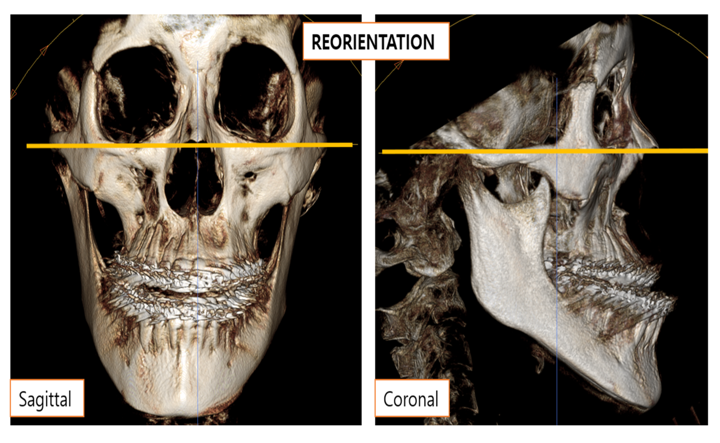
2.2. Skeletal Measurements

Table 2 describes the landmarks and reference planes assigned for the skeletal measurements. The skeletal measurements were taken using INVIVO version 5.0 software. The superimposition function was used to measure the skeletal changes after surgery using the anterior cranial base as reference (Figure 1). First, the pre-operative CBCT was opened. Then, volume rendering tab reorientation of the CBCT was performed according to the Frankfort horizontal (FH) plane (Figure 2). Then, the post-operative CBCT was imported under the superimposition tab. Point registration was performed using stable landmarks, namely the right and left zygomaticofrontal suture and orbitale. Volume registration was then done for fine adjustments (Figure 3).
At time points T0, T1 and T2, the total pharyngeal volume and cross-sectional area across five different planes in the upper airway were measured from the CBCT images (Figure 4). Nasopharynx region is placed at between plane 1 and 2. Plane 3 is a velopharynx region. The oropharynx region is placed at between plane 4 and 5. The change in the tongue position was determined on a T-y and T-x reference planes. The difference in the perpendicular positioning of the tongue (y-axis) was measured on T-y plane which was placed parallel and 20 mm in front of the vertical reference plane as depicted in Figure 1. The change in the anteroposterior position (x-axis) was measured on T-x plane which was parallel to the FH plane and passes through second cervical vertebra. The T-y and T-x plane are necessary for measuring tongue position from a uniform registered point. The change in the position of B point in the antero-posterior direction was calculated in the midsagittal plane from the CBCT images. The difference in the position of the maxilla was calculated from the movement of the posterior nasal spine (PNS) in the anteroposterior direction as well as the vertical direction in the mid-sagittal plane. The most anterosuperior point of the hyoid bone was marked, and the change was calculated in the anteroposterior and superoinferior directions.

2.3. Reconstruction of the Model and Mesh Generation

The 3D-DOCTOR software was used for the reconstruction of the airway models for all patients. About 600 images of the upper airway were segmented with a threshold value between −1024 to −480 Hounsfield units. Figure 5 shows the anatomy of the upper airway, which has the smallest area. Given the complexity of the morphological characteristics of the upper airway, setting the fluid domain is vital for analysis. As anatomy can significantly change the facial features of people, an understanding of the interior anatomy of humans can solve this problem. The highest number of obstruction sites detected by studies were at the level of the oropharynx [21]. A collapse occurs close to the velopharynx or oropharynx. The total fluid domain was set from the nasal vestibule to the laryngopharynx. Using the CT data, the modeling process was subsequently executed using the following steps. First, the extracted boundary was set on the CT images. Then, the boundary piles on the CT images were laminated, and finally, the model created through the lamination was cleaned and saved in stereolithography (STL) format. It should be noted that numerous other methods can be used for creating models in commercial programs. Anatomically accurate 3D models were converted to the STL format (Figure 5 and Figure 6). The STL files were then imported to the integrated computer engineering and manufacturing code for CFD (ICEM-CFD). Meshing was performed on the prism and tetrahedral meshes generated by ICEM-CFD. The meshing elements and nodes were taken from pre-operation cases at 1.21 × 10⁶ and 6.25 × 10⁶, and post-operation cases at 1.90 × 10⁶ and 6.89 × 10⁶, respectively. The finite volume approaches of the cells’ near-wall boundary were irregular, which may require tailored treatment. The prisms can first create a layer of regular prisms near the wall and then mesh the remaining volume with tetrahedrons. This grid approach gives better solutions and convergence of computation [22]. A grid invariant study was performed to check the grid independence of the simulation meshes. This compared three different meshes (fine: 1.67 × 10⁷ meshes; mild: 8.16 × 10⁶ meshes; and coarse: 4.6 × 10⁶ meshes) for the pre-operative patient 5 model. In terms of average velocity at the minimal cross-sectional area, the coarse case and mild case had a disparity of 2.65% and the disparity within the mild case and fine case was 2.27%. Thus, the meshes in the moderate case proved to be satisfactory for describing the airflow dynamics of the upper airway.

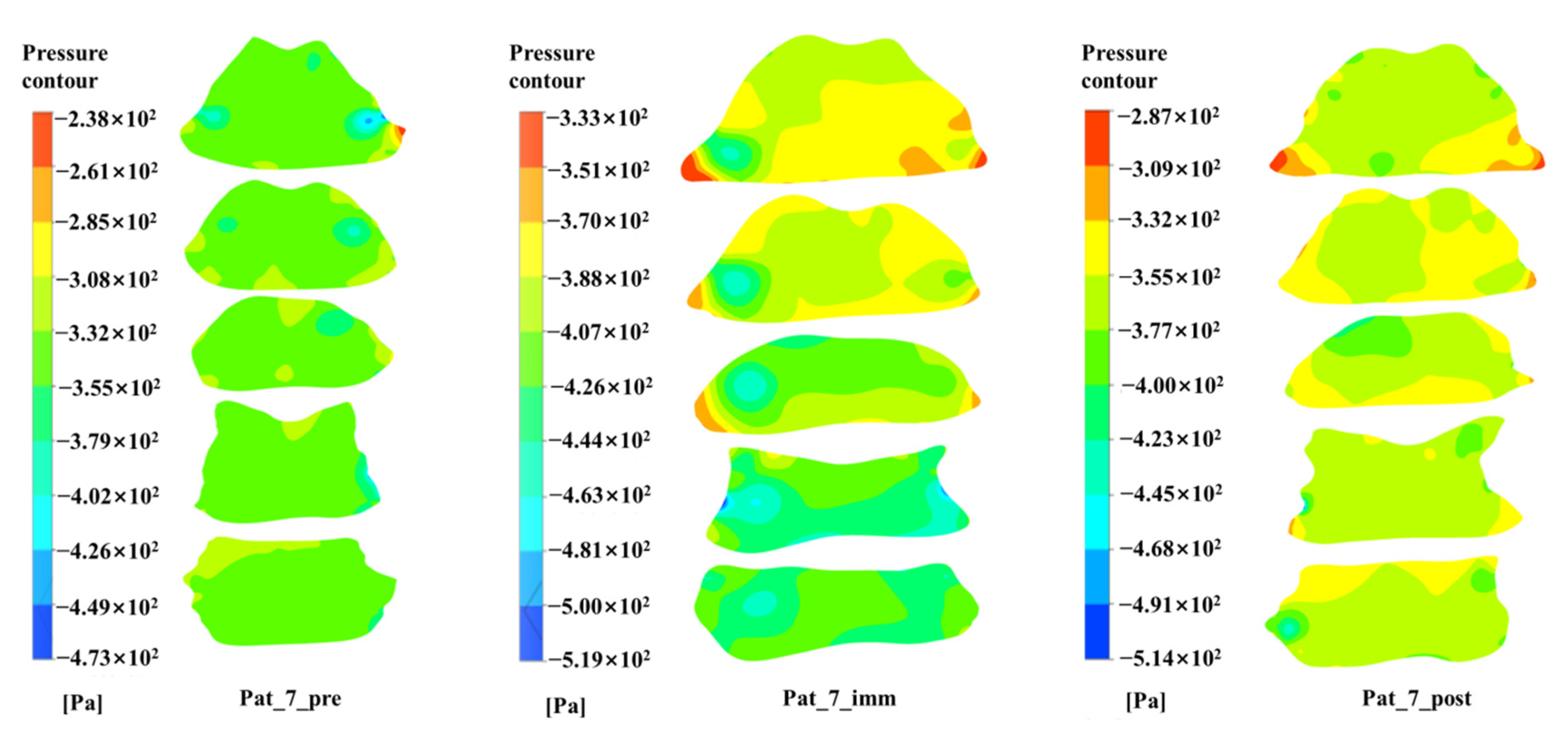
2.4. Computational Fluid Dynamics

In this study, the commercial CFD code, ANSYS-CFX 19.2 (ANSYS, Inc., 2012, Canonsburg, PA, USA), which is finite volume method dependent, was used for airflow simulations in the pharyngeal airway before (T0), immediately after (T1) and at least 6 months (T2) after orthognathic surgery. The flow assumes an incompressible fluid as the velocity of the air was slow, and the Mach number was lower than 0.3. The following properties of air were used: 1.185 kg/m3 and 1.831 × 10⁻⁵ kg/m·s. The boundary conditions can be classified in several ways. In the simulation, conditions are ideal if real-time data are used for calculation. One of the major reasons behind upper airway simulations is data acquisition to predict a collapse and identify relevant parameters. The inlet boundary condition was imposed on the opening boundary conditions for atmospheric pressure, which means the gauge pressure was 0 Pa. The outlet boundary condition was used as the mass flow boundary condition to simulate normal respiration (500 mL) composed with a half sinusoidal wave function(Q = ((0.00265[m3] + 0.00025[m3] × sin(2πt/5[s])) × 1[s−1] × 1.185[kg/m3]) for a single breath. The mass flow rate was determined with realistic breathing conditions [23]. The total time was 3.8 s of physical time, amidst Δt = 5 × 10⁻³ s of time steps. The airflow problem for time integration was solved using the second-order implicit unsteady scheme. A no-slip boundary condition was imposed on the upper airway wall. The same boundary conditions were assigned to all patients to focus on the anatomical model effect on the outcome.
The Reynolds number (Re) can define flow patterns in different fluid flow situations. At low Reynolds numbers, flows is likely to be laminar flow, while at high Reynolds numbers flows is likely to be turbulent. The Re number is defined as:
Re = ρ u L μ
Here, ρ is the density, u is the airflow velocity, μ is the dynamic viscosity L is the characteristic length.
The Re number of the upper airway model used in this study had a range of 8 × 10³ to 2 × 10⁴. The section of the minimum area in the upper airway is known to be generated by turbulence phenomena [24,25]. Although direct numerical simulations and large eddy simulation can provide more accurate and detailed data, it requires a mesh size that is too small [26,27]. For the simulation, Reynolds-averaged Navier–Stokes (RANS) equations without external forces were used as a turbulence model along with Menter’s shear stress transport (SST) turbulence model [28,29]. Among all the RANS models applied, the k-ω SST turbulence model was more reasonable due to less difference as compared with large eddy simulation LES [30]. The k-ω SST turbulence model presents a good combination both the original k-ω and the standard k-ε turbulence model in terms of prediction to flow near wall region which occurs adverse pressure gradients by separation and free shear region. The second-order finite volume schemes are adopted for discretizing the equation conducting flow simulation. A turbulence intensity of 10% was used at the inlet boundary condition.
The mass and momentum conservation equations are shown in Equations (2) and (3):
ρ t + ρ u i x j = 0
ρ u i t + u i ρ u j x j = P x i + x j μ + μ t u i x j + u j x i
Here, ui is the airflow velocity vector, P′ (Equation (4)) expresses modified pressure, and μt is the eddy viscosity or turbulent viscosity. The unknown turbulent viscosity μt (Equation (5)) is determined by solving the two additional transport equations for turbulent kinetic energy k, and specific dissipation of turbulence kinetic energy ω.
P = P + 2 3 ρ k + 2 3 μ + μ t u k x k
μ t = ρ k ω
ρ k t + ρ u j k x j = P k β * ρ ω k + x j μ + σ k μ t + k x j
ρ ω t + ρ u j ω x j = γ P ω β ρ ω 2 + x j μ + σ ω μ t + ω x j + 2 ρ 1 F 1 σ ω 2 1 ω k x j ω x j
The k-ω SST turbulence model is shown in Equations (6) and (7), where x is the Cartesian coordinate, P is the production of the kinetic energy of turbulence, σ and β are the turbulence model coefficients, β* and γ are the turbulence model coefficients that are modified with low Reynolds numbers, and F1 is the auxiliary function in the turbulence model.

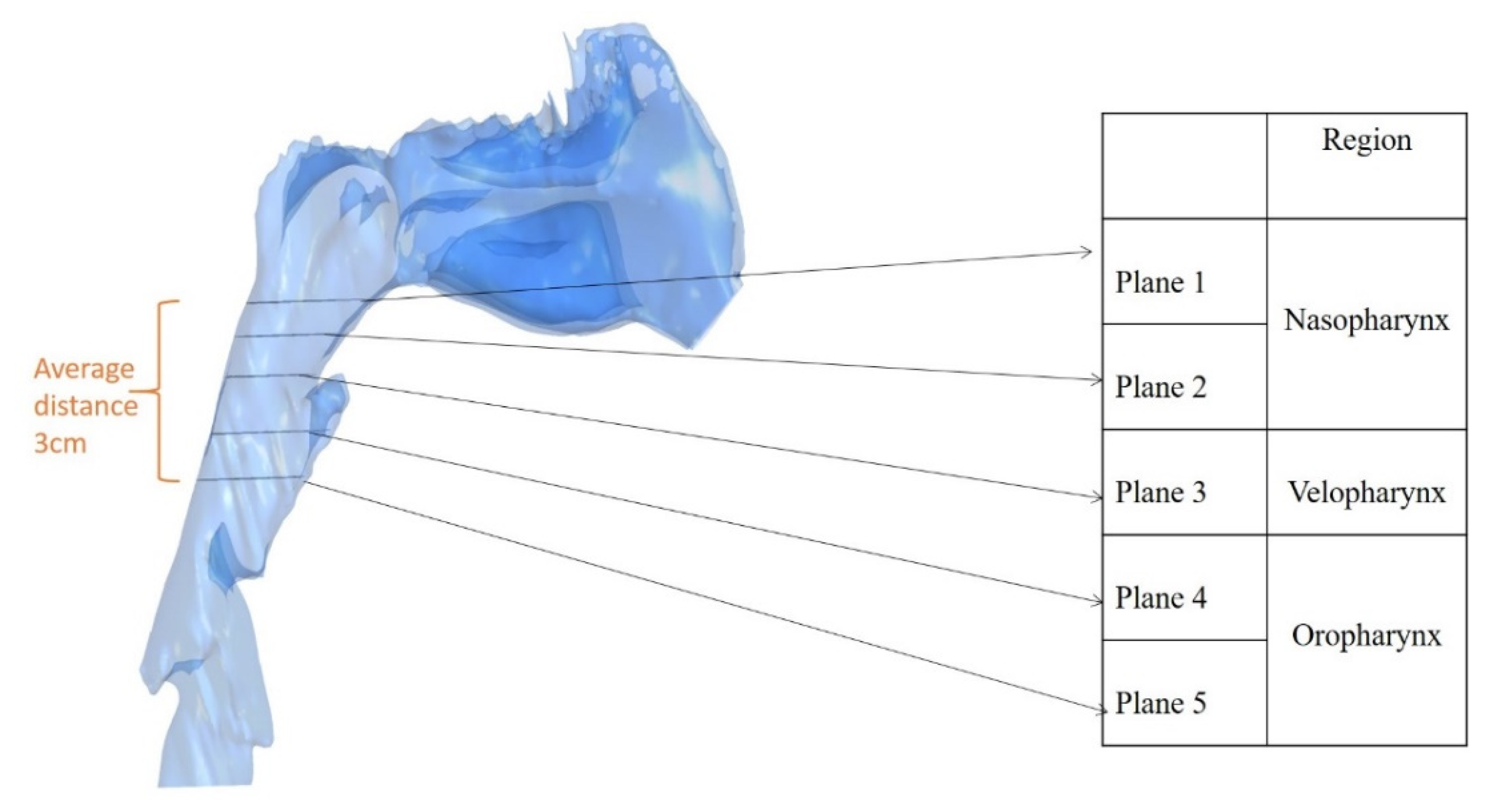
2.5. Outcome Parameters

Studies on the upper respiratory tract including lungs through in vitro experiments and numerical simulations have been continuously conducted [17,18,23,24,25,26,27]. Many studies have been carried out numerically, and many researchers have tried to derive the evaluation of OSA, the likelihood of occurrence, or predictive factors through various factors [18,23,24,26,27,31]. The main factors considered so far are velocity field, pressure field, pressure drop, wall shear stress, resistance and so on. Among these, the velocity field and helicity are important factors that help us to understand the flow pattern inside the upper airway [31]. In addition, among the variables considered, adjusted pressure coefficient (APC) and pressure drop showed a significant correlation with the clinical value as a parameter calculated by CFD [26].
In this study, the cross-sectional area of five planes in the pharyngeal region, along with the total volume of the pharynx, was calculated. The skeletal changes after surgery were calculated. The change was calculated in the horizontal (x) and vertical (y) directions. Change in B point, PNS, tongue displacement, and the position of the hyoid bone was measured in the x and y directions from the horizontal and vertical reference planes. The pressure drop from plane 1 to plane 5 and the adjusted pressure coefficient were calculated using computational fluid dynamics simulations as follows:
Pressure   Drop =   P p l a n e   5 P p l a n e   1
Adjusted   Pressure   Coefficient   = P p l a n e   5     P p l a n e   1   V p l a n e 3 2

2.6. Statistical Analysis

Technical error measurement calculation was undertaken using the following formula:
d 2 2 n
d is the difference between the two measurements and n is the sample size to be remeasured.
The skeletal measurements were made twice 1 week apart and reliability of the measurements was assessed using intraclass correlation coefficient. IBM SPSS (version 22.0, Armonk, NY, USA) was used for the statistical analysis. Power analysis and sample size estimation were undertaken to analyze the experimental design reliability. The Wilcoxon signed-rank test was used to compare the pre- and post-surgical outcomes. Spearman’s correlation coefficient was used to examine correlations between the surgical movement and airflow characteristics.

3. Results

The technical error measurement value calculated as percentage was below 1.5% for all linear, volumetric and cross-sectional measurements. The intraclass correlation coefficient was within an acceptable range from 0.786 to 0.953 indicating good intrarater reliability. The power analysis (based on the paired mean test) for sample size of 11 depicted 80% probability for detection of change in pressure drop postoperatively.

3.1. Comparison of the Pre- and Post-Operative Measurements

Figure 7 shows the distribution of the streamline in patient 10 during inspiration (t = 1.25 s). When examining the streamline inside the upper respiratory tract during inspiration, it can be observed that vortices are largely generated as they flow through the nasal cavity and flow into the nasopharynx. This is because the complex anatomical structure of the nasal cavity creates vortices and airflow through the airways. It was confirmed that this effect continued to the oropharynx. Na et al. reported that upper airway with retruded jaw exhibits various-scale vortexes and a strong pressure drop [31]. The change in the cross-sectional area of the planes and total volume are shown in Table 3 and Table 4. Looking at the cross-sectional area change in each section depending on the timing of the operation in Table 3, the cross-sectional area of the nasopharynx (plane 1 and 2) in immediate post-operative (T1) decreases from the initial area to 67.7% and 71.6% respectively. At 6 months after surgery (T2), the initial area was recovered to 97% and 93.6%. There are many factors such as natural recovery and obesity, so further analysis is needed on why the recovery is taking place. In the velopharynx, this was reduced to 64.2% of the initial area at T1, and it was shown to be 95.6% of the initial area at T2. Finally, in the oropharynx, the initial area decreased to 61.7% and 61.3% of the initial area at T1 and then to about 87% and 95.6% of the initial area at T2. Therefore, it was shown that most of the initial areas were reduced by 60% immediately after surgery, and then recovered by 90% 6 months after surgery. Similarly, total volume decreased to 77.1% of the initial volume at T1 and then to 92.2% of the initial volume at T2.
The airflow computation analysis showed a gradual decrease in the pressure drop. The adjusted pressure coefficient increased slightly, but this was statistically insignificant (Table 5). Taherian, S., et al. showed that APC is proportional to AHI value and has a range of 0.5 to 2.0 [26]. In this study, APC was 0.48 before surgery and increased to 0.59 after surgery. The increase in APC is reasonable, since the patient’s average manual setback is 5 mm, and maxillary enhancement is 2 mm, and the airway becomes narrower after surgery.
The velocity profile of the central line of planes 1–5 of representative patient 7 are shown in Figure 8. The velocity profile was different at each point in time. The pressure drop distribution of planes 1–5 of representative patient 7 are shown in Figure 9. It was observed that a large external low pressure area occurred at T1 and stabilized at T2.

3.2. Correlation between the Surgical Changes and Outcome Parameters

The change in the pressure drop value was significantly correlated to the posterior movement of the tongue, and the cross-sectional area change in plane 2 (Table 6). The pressure drop values calculated in different phases changes in accordance with the amount of backward movement of tongue. The change in pressure drop after 6 months is also dependent on cross-sectional area changes as in plane 2. Other significant correlations among surgical parameters are shown in Table 7. The change in total volume was significantly correlated to the changes in the cross-sectional area of planes 1, 3 and 4. However, there was no correlation found between the total volume change and the pressure drop changes. Some other surgically significant correlations showed vertical movement of the tongue was significantly correlated to the vertical movement of the B point (r = 0.7, p = 0.036). The horizontal movement of the hyoid bone was significantly correlated to the horizontal movement of the tongue (r = −0.7 p = 0.036). The vertical movement of the hyoid bone was significantly correlated to the vertical B point movement (r = 0.91 p = 0.00), horizontal movement of the tongue (r = 0.67, p = 0.050), and horizontal movement of the PNS (r = 0.61, p = 0.046).

4. Discussion

The current study was conducted to evaluate the alterations in pharyngeal airway airflow characteristics of adult patients with class III skeletal malocclusion who were treated with maxillary advancement and mandibular setback surgery using CFD. The cross-sectional area and total volume of the pharyngeal airway decreased after surgery. As a result of examining the cross-sectional area of the upper airway before (T0), immediately after (T1), and 6 months after (T2) the surgery, it was confirmed that some of the upper airway characteristics such as cross-sectional area and volume were restored. In the vicinity of the velopharynx and oropharynx, where closures due to closed sleep apnea are likely to occur, the cross-sectional area was reduced to about 60% of the initial section area at T1 and recovered to 95% of the initial section area at T2. This can also be seen as an evidence that postoperative weight management may also affect future symptoms. There was a decrease in the pressure drop values after surgery. The airflow changes correlated with relevant anatomical changes during surgery. The latest proposed CFD-based parameter, APC, was shown in the normal range from 0.48 to 0.59 [26]. As noted in the reference, the greater the closure, the greater the APC.
Previous studies have shown an association between cross-sectional changes and OSA [32,33,34]. Cross-sectional airway changes due to a change in the tongue position are more likely to affect pharyngeal airway obstruction [23]. In this study, a correlation between changes in the pressure drop values, and the tongue position was confirmed. The tongue’s dorsal surface revealed a superior and backward movement, which is in accordance with another study. The backward positioning of the tongue following mandible setback surgery tends to have an elongation effect laterally on the airway [4]. In our study, no statistically significant change in the cross-sectional area of any plane was observed. This may be due to the simultaneous maxillary advancement procedure, which reduced the need for a large mandibular setback. In agreement with other studies, the total volume of the pharyngeal airway does not show a statistically significant change due to the simultaneous forward shift of the PNS [5,11].
The pharyngeal airway dimension is also related to the hyoid bone positioning owing to insertion of the hyoglossus muscle. A posteroinferior shift of the hyoid bone was observed in the current study, which is in agreement with previous studies [35,36]. Kim et al. found a negative correlation between pharyngeal volume and the inferior movement of the hyoid bone [35]. Although no such correlation was found in our study, the posterior and inferior movement of the hyoid bone was correlated to the posterior movement of the tongue.
This study has several limitations. First, the CBCT was taken with the patient in an upright position, whereas a supine position might provide better information regarding the pharyngeal airway. Second, the sample size and follow-up time were both small. While some studies have shown morphological changes after a long follow-up period, the airflow characteristics post-surgery have not been elucidated well. Finally, CFD results should be verified by experiment [37]. Quantitative data verification will be required in the future through current visualization techniques such as particle image velocimetry (PIV), which are currently being prepared. Further studies could use a longer follow-up period. Moreover, future studies should also investigate the influence of other factors, such as ethnicities or dietary habits, on the results.

5. Conclusions

Bimaxillary orthognathic surgery does not significantly reduce pharyngeal volume post-surgery. There was statistically insignificant reduction of the cross-sectional area. It was confirmed that the cross-sectional area of the upper respiratory tract was partially restored after 6 months of surgery. Mandibular set back was found to affect the tongue and hyoid bone positioning. A decrease in the pressure drop due to the backward movement of the tongue was observed. Pressure drop changes are more susceptible to cross-sectional area changes than to the total volume of the pharynx.

Author Contributions

Conceptualization, P.W., H.-H.K. and E.-S.L.; methodology, P.W., H.-S.J., H.-H.K. and E.-S.L.; software, P.W. and H.-H.K.; validation, P.W., H.-S.J., H.-H.K. and E.-S.L.; formal analysis, P.W., S.-H.P. and H.-H.K.; investigation, P.W., H.-S.J., S.-H.P. and H.-H.K.; resources, P.W., S.-H.P. and H.-H.K.; data curation, H.-S.J. and H.-H.K.; writing—original draft preparation, P.W., H.-S.J., S.-H.P. and H.-H.K.; writing—review and editing, P.W., H.-S.J., E.-S.L. and H.-H.K.; visualization, P.W., H.-S.J., S.-H.P., H.-H.K. and E.-S.L.; supervision, H.-H.K., E.-S.L.; project administration, H.-S.J., E.-S.L. and H.-H.K. All authors have read and agreed to the published version of the manuscript.

Funding

This work was supported by the research invigoration program of 2020 Gyeongnam National University of Science and Technology.

Institutional Review Board Statement

The study was done in accordance with the declaration of Helsinki and was approved by the Institutional Review Board of Korea University Guro Hospital [(irb.kumc.or.kr) IRB No. 2021GR0020].

Data Availability Statement

The data that support the findings of this study are available from the corresponding author, upon reasonable request.

Conflicts of Interest

The authors declare no conflict of interest.

References

  1. Croce, C.; Fodil, R.; Durand, M.; Sbirlea-Apiou, G.; Caillibotte, G.; Papon, J.-F.; Blondeau, J.-R.; Coste, A.; Isabey, D.; Louis, B. In Vitro Experiments and Numerical Simulations of Airflow in Realistic Nasal Airway Geometry. Ann. Biomed. Eng. 2006, 34, 997–1007. [Google Scholar] [CrossRef] [PubMed]
  2. Ferziger, J.H.; Peric, M. Computational Methods for Fluid Dynamics, 3rd ed.; Springer: Berlin/Heidelberg, Germany, 2002; p. 426. [Google Scholar]
  3. Gokce, S.M.; Görgülü, S.; Gokce, H.S.; Bengi, A.O.; Karacayli, U.; Ors, F. Evaluation of pharyngeal airway space changes after bimaxillary orthognathic surgery with a 3-dimensional simulation and modeling program. Am. J. Orthod. Dentofac. Orthop. 2014, 146, 477–492. [Google Scholar] [CrossRef] [PubMed]
  4. Gonçales, E.S.; Rocha, J.F.; Gonçales, A.G.; Yaedú, R.Y.; Sant’Ana, E. Computerized cephalometric study of the pharyngeal airway space in patients submitted to orthognathic surgery. J. Maxillofac. Oral Surg. 2013, 13, 253–258. [Google Scholar] [CrossRef] [PubMed] [Green Version]
  5. Gottsauner-Wolf, S.; Laimer, J.; Bruckmoser, E. Posterior Airway Changes Following Orthognathic Surgery in Obstructive Sleep Apnea. J. Oral Maxillofac. Surg. 2018, 76, 1093.e1–1093.e21. [Google Scholar] [CrossRef]
  6. Jakobsone, G.; Neimane, L.; Krumina, G. Two- and three-dimensional evaluation of the upper airway after bimaxillary correction of Class III malocclusion. Oral Surg. Oral Med. Oral Pathol. Oral Radiol. Endodontol. 2010, 110, 234–242. [Google Scholar] [CrossRef]
  7. Jang, S.-I.; Ahn, J.; Paeng, J.-Y.; Hong, J. Three-dimensional analysis of changes in airway space after bimaxillary orthognathic surgery with maxillomandibular setback and their association with obstructive sleep apnea. Maxillofac. Plast. Reconstr. Surg. 2018, 40, 33. [Google Scholar] [CrossRef]
  8. Jeong, S.; Sung, J.; Kim, Y.-D.; Shin, S.; Kim, S.-S. Upper airway morphologic changes after mandibular setback surgery in skeletal class III malocclusion patients measured using cone beam computed tomography superimposition. Int. J. Oral Maxillofac. Surg. 2018, 47, 1405–1410. [Google Scholar] [CrossRef]
  9. Katiyar, R.; Singh, G.K.; Mehrotra, D.; Singh, A. Surgical–orthodontic treatment of a skeletal class III malocclusion. Natl. J. Maxillofac. Surg. 2010, 1, 143–149. [Google Scholar] [CrossRef] [Green Version]
  10. Kim, H.Y.; Bok, K.H.; Dhong, H.-J.; Chung, S.-K. The correlation between pharyngeal narrowing and the severity of sleep-disordered breathing. Otolaryngol. Head Neck Surg. 2008, 138, 289–293. [Google Scholar] [CrossRef]
  11. Kim, M.A.; Kim, B.R.; Choi, J.Y.; Youn, J.K.; Kim, Y.J.; Park, Y.H. Three-dimensional changes of the hyoid bone and airway volumes related to its relationship with horizontal anatomic planes after bimaxillary surgery in skeletal Class III patients. Angle Orthod. 2013, 83, 623–629. [Google Scholar] [CrossRef] [Green Version]
  12. Lee, Y.; Chun, Y.S.; Kang, N.; Kim, M. Volumetric changes in the upper airway after bimaxillary surgery for skeletal class III malocclusions: A case series study using 3-dimensional cone-beam computed tomography. J. Oral Maxillofac. Surg. 2012, 70, 2867–2875. [Google Scholar] [CrossRef] [PubMed]
  13. Lu, M.Z.; Liu, Y.; Ye, J.Y.; Luo, H.Y. Large Eddy Simulation of Flow in Realistic Human Upper Airways with Obstructive Sleep. Procedia Comput. Sci. 2014, 29, 557–564. [Google Scholar] [CrossRef] [Green Version]
  14. Menter, F.R. Two-equation eddy-viscosity turbulence models for engineering applications. AIAA J. 1994, 32, 1598–1605. [Google Scholar] [CrossRef] [Green Version]
  15. Mihaescu, M.; Murugappan, S.; Kalra, M.; Khosla, S.; Gutmark, E. Large Eddy Simulation and Reynolds-Averaged Navier-Stokes modeling of flow in a realistic pharyngeal airway model: An investigation of obstructive sleep apnea. J. Biomech. 2008, 41, 2279–2288. [Google Scholar] [CrossRef]
  16. Mihaescu, M.; Mylavarapu, G.; Farbos de Luzan, C.; Gutmark, E.; Powell, N. Large Eddy Simulation for Estimating Flow Instabilities Associated with Obstructive Sleep Apnea in a Pharyngeal Airway. In Proceedings of the International Conference on Jets, Wakes and Separated Flows, ICJWSF-2010, Cincinnati, OH, USA, 27–30 September 2010. [Google Scholar]
  17. Na, J.S.; Jung, H.D.; Cho, H.J.; Choi, Y.J.; Lee, J.S. Computational analysis of airflow dynamics for predicting collapsible sites in the upper airways: A preliminary study. J. Appl. Physiol. 2019, 126, 330–340. [Google Scholar] [CrossRef]
  18. Piao, Y.; Kim, S.J.; Yu, H.S.; Cha, J.Y.; Baik, H.S. Five-year investigation of a large orthodontic patient population at a dental hospital in South Korea. Korean J. Orthod. 2016, 46, 137–145. [Google Scholar] [CrossRef] [Green Version]
  19. Borojeni, A.A.T.; Garcia, G.J.M.; Moghaddam, M.G.; Frank-Ito, D.O.; Kimbell, J.S.; Laud, P.W.; Koenig, L.J.; Rhee, J.S. Normative ranges of nasal airflow variables in healthy adults. Int. J. Comput. Assist. Radiol. Surg. 2020, 15, 87–98. [Google Scholar] [CrossRef]
  20. Borojeni, A.A.T.; Frank-Ito, D.O.; Kimbell, J.S.; Rhee, J.S.; Garcia, G.J. Creation of an idealized nasopharynx geometry for accurate computational fluid dynamics simulations of nasal airflow in patient-specific models lacking the nasopharynx anatomy. Int. J. Numer. Methods Biomed. Eng. 2016, 33, e2825. [Google Scholar] [CrossRef] [Green Version]
  21. Rama, A.N.; Tekwani, S.H.; Kushida, C.A. Sites of obstruction in obstructive sleep apnea. Chest 2002, 122, 1139–1147. [Google Scholar] [CrossRef] [Green Version]
  22. Sascău, R.; Zota, I.M.; Stătescu, C.; Boișteanu, D.; Roca, M.; Maștaleru, A.; Constantin, M.M.L.; Vasilcu, T.F.; Gavril, R.S.; Mitu, F. Review of Echocardiographic Findings in Patients with Obstructive Sleep Apnea. Can. Respir. J. 2018, 2018, 1206217. [Google Scholar] [CrossRef] [Green Version]
  23. Shin, J.H.; Kim, M.A.; Park, I.Y.; Park, Y.H. A 2-year follow-up of changes after bimaxillary surgery in patients with mandibular prognathism: 3-dimensional analysis of pharyngeal airway volume and hyoid bone position. J. Oral Maxillofac. Surg. 2015, 73, 340.e1–340.e9. [Google Scholar] [CrossRef] [PubMed]
  24. Shivalkar, B.; Van de Heyning, C.; Kerremans, M.; Rinkevich, D.; Verbraecken, J.; De Backer, W.; Vrints, C. Obstructive sleep apnea syndrome: More insights on structural and functional cardiac alterations, and the effects of treatment with continuous positive airway pressure. J. Am. Coll. Cardiol. 2006, 47, 1433–1439. [Google Scholar] [CrossRef] [PubMed] [Green Version]
  25. Taherian, S.; Rahai, H.; Gomez, B.; Waddington, T.; Mazdisnian, F. Computational fluid dynamics evaluation of excessive dynamic airway collapse. Clin. Biomech. 2017, 50, 145–153. [Google Scholar] [CrossRef] [PubMed]
  26. Taherian, S.; Rahai, H.; Lopez, S.; Shin, J.; Jafari, B. Evaluation of human obstructive sleep apnea using computational fluid dynamics. Commun. Biol. 2019, 2, 423. [Google Scholar] [CrossRef] [PubMed] [Green Version]
  27. Taherian, S.; Rahai, H.R.; Bonifacio, J.; Gomez, B.Z.; Waddington, T. Particulate Deposition in a Patient with Tracheal Stenosis. J. Eng. Sci. Med. Diagn. Ther. 2017, 1, 011005. [Google Scholar] [CrossRef] [Green Version]
  28. Tan, S.K.; Tang, A.T.H.; Leung, W.K.; Zwahlen, R.A. Three-Dimensional Pharyngeal Airway Changes After 2-Jaw Orthognathic Surgery with Segmentation in Dento-Skeletal Class III Patients. J. Craniofacial Surg. 2019, 30, 1533–1538. [Google Scholar] [CrossRef]
  29. Tepecik, T.; Ertaş, Ü.; Akgün, M. Effects of bimaxillary orthognathic surgery on pharyngeal airway and respiratory function at sleep in patients with class III skeletal relationship. J. Cranio-Maxillofac. Surg. 2018, 46, 645–653. [Google Scholar] [CrossRef]
  30. Vos, W.; De Backer, J.; Devolder, A.; Vanderveken, O.M.; Verhulst, S.; Salgado, R.; Germonpre, P.; Partoens, B.; Wuyts, F.; Parizel, P.; et al. Correlation between severity of sleep apnea and upper airway morphology based on advanced anatomical and functional imaging. J. Biomech. 2007, 40, 2207–2213. [Google Scholar] [CrossRef]
  31. Wiedemeyer, V.; Berger, M.; Martini, M.; Kramer, F.J.; Heim, N. Predictability of pharyngeal airway space dimension changes after orthognathic surgery in class II patients: A mathematical approach. J. Cranio-Maxillofac. Surg. 2019, 47, 1504–1509. [Google Scholar] [CrossRef]
  32. Wilcox, D.C. Turbulence Modeling for CFD. In Turbulence Modeling for CFD, 1st ed.; DCW Industries, Inc.: La Cañada Flintridge, CA, USA, 1994. [Google Scholar]
  33. Wootton, D.M.; Luo, H.; Persak, S.C.; Sin, S.; McDonough, J.M.; Isasi, C.R.; Arens, R. Computational fluid dynamics endpoints to characterize obstructive sleep apnea syndrome in children. J. Appl. Physiol. 2014, 116, 104–112. [Google Scholar] [CrossRef]
  34. Xu, C.; Sin, S.; McDonough, J.M.; Udupa, J.K.; Guez, A.; Arens, R.; Wootton, D.M. Computational fluid dynamics modeling of the upper airway of children with obstructive sleep apnea syndrome in steady flow. J. Biomech. 2006, 39, 2043–2054. [Google Scholar] [CrossRef] [PubMed]
  35. Zhao, M.; Barber, T.; Cistulli, P.; Sutherland, K.; Rosengarten, G. Computational fluid dynamics for the assessment of upper airway response to oral appliance treatment in obstructive sleep apnea. J. Biomech. 2013, 46, 142–150. [Google Scholar] [CrossRef] [PubMed]
  36. Zheng, Z.; Liu, H.; Xu, Q.; Wu, W.; Du, L.; Chen, H.; Zhang, Y.; Liu, D. Computational fluid dynamics simulation of the upper airway response to large incisor retraction in adult class I bimaxillary protrusion patients. Sci. Rep. 2017, 7, 45706. [Google Scholar] [CrossRef] [PubMed] [Green Version]
  37. Fan, Y.; Dong, J.; Tian, L.; Inthavong, K.; Tu, J. Numerical and Experimental Analysis of Inhalation Airflow Dynamics in a Human Pharyngeal Airway. Int. J. Environ. Res. Public Health 2020, 17, 1556. [Google Scholar] [CrossRef] [PubMed] [Green Version]
Figure 1. Skeletal measurements using superimposition of the pre- and post-cone-beam computed tomography (CBCT).
Processes 09 00152 g001
Figure 2. Reorientation of the CBCT according to the Frankfort horizontal plane.
Processes 09 00152 g002
Figure 3. Superimposition of the pre- and post-surgery CBCT. (A) First, the point registration function was used by marking stable landmarks in the pre- and post-CBCT. (B) Second, the volume registration function was used for fine adjustments. The before and after volume registrations can be seen. The superimposition can be checked from the alignment of the anterior cranial base marked by arrows.
Processes 09 00152 g003
Figure 4. Different planes for the cross-sectional measurement. The boundary of the upper airway was studied between planes 1 and 5.
Processes 09 00152 g004
Figure 5. (A) Segmented pharyngeal airway. (B) Anatomical 3D model of pharyngeal airway was created using CBCT.
Processes 09 00152 g005
Figure 6. Superimposition of the pre- and post-pharyngeal airway model.
Processes 09 00152 g006
Figure 7. Streamline distribution in patient 10 during inspiration (t = 1.25 s).
Processes 09 00152 g007
Figure 8. Velocity profile in patient 7 between planes 1–5 (t = 1.25 s).
Processes 09 00152 g008
Figure 9. Pressure distribution in patient 7 between planes 1–5 (t = 1.25 s).
Processes 09 00152 g009
Table 1. Details of the patients included in the computational fluid dynamics (CFD) simulation.
Original Patient NumberAge/SexBMI (kg/m2)Pre-Operative (T0)
Immediate Post-Operative (T1)
6 Months Post-Operative (T2)
Patient 123/M22.7T0, T2
Patient 219/M20.5T0, T2
Patient 319/M25.9T0, T1, T2
Patient 419/F18.9T0, T2
Patient 520/F24.3T0, T2
Patient 620/F22.7T0, T1, T2
Patient 721/M24.9T0, T1, T2
Patient 822/F19.1T0, T2
Patient 926/F19.2T0, T2
Patient 1018/F19.9T0, T2
Patient 1133/M23.5T0, T1, T2
BMI: Body mass index.
Table 2. The landmarks and reference planes used.
Landmarks
PNSThe most posterior point of the hard palate.
B PointThe deepest anterior point in the concavity of the anterior mandible.
A PointMost concave point of anterior maxilla
Reference planes
FH PlaneConstructed on both sides of Po and to the right of the orbitale.
Vertical Reference PlanePerpendicular to the FH plane passing through sella turcica.
T-y PlaneParallel to the vertical reference plane and 20 mm in front.
T-x PlaneParallel to the FH plane and passing through the most anterior inferior point of the body of the second cervical vertebra.
PNS: Posterior nasal spine; Po: Porion; FH: Frankfort horizontal.
Table 3. Cross-sectional area (cm2) in the different planes (mean + standard deviation (SD)).
T0T1p-ValueT2p-Value
NasopharynxPlane 14.61 ± 1.712.82 ± 1.100.1444.05 ± 1.720.066
Plane 23.77 ± 1.622.7 ± 0.770.0683.53 ± 1.690.441
VelopharynxPlane 32.96 ± 1.641.9 ± 0.750.0682.83 ± 1.710.173
OropharynxPlane 43.76 ± 1.742.32 ± 1.060.1443.28 ± 1.700.051
Plane 53.47 ± 1.822.13 ± 0.400.0683.32 ± 1.830.314
Table 4. Cross-sectional area (cm2) in the different planes (mean + SD).
T0T1p-ValueT2p-Value
Total volume62.04 ± 19.747.88 ± 9.060.46557.25 ± 11.60.534
Table 5. Results of the CFD simulations (mean + SD).
Pressure Drop (Pa) Adjusted Pressure Coefficient
T0T1p-ValueT2p-ValueT0T1p-ValueT2p-Value
1.25 s
I.P.
−54.68 ± 103.66−101.5 ± 140.20.144−119.18 ± 154.90.0750.48 ± 0.120.44 ± 0.1710.59 ± 0.240.139
2.5 s
R.P.
−48.17 ± 92.30−86.34 ± 114.30.144−207.21 ± 379.80.0750.47 ± 0.180.45 ± 0.160.7150.57 ± 0.240.050
3.75 s
E.P.
−40.40 ± 78.47−72.68 ± 93.900.144−160.71 ± 288.590.0750.46 ± 0.180.61 ± 0.080.1750.55 ± 0.250.212
I.P.: Inspiration Phase; R.P.: Rest Phase; E.P.: Expiration Phase.
Table 6. Correlation between the surgical changes and airflow characteristics.
Δ Pressure DropΔ Adjusted Pressure Coefficient
1.25 s
I.P.
2.5 s
R.P.
3.75 s
E.P.
1.25 s
I.P.
2.5 s
R.P.
3.75 s
E.P.
Tongue xr0.6380.6150.597−0.565−0.553−0.534
p-value0.035 *0.044 *0.0530.0700.0780.091
Δ Plane 2r0.6550.6550.618−0.355−0.560−0.433
p-value0.029 *0.029 *0.043 *0.2850.0730.183
I.P.: Inspiration Phase; R.P.: Rest Phase; E.P.: Expiration Phase; r: Spearman’s correlation coefficient; *: Statistically significant.
Table 7. Correlation between the cross-sectional area and skeletal changes.
Δ VolumeHyoid (y-Axis)Tongue (x-Axis)
Δ Plane 1r = 0.8 p = 0.000-r = 0.7 p = 0.023
Δ Plane 2- -
Δ Plane 3r = 0.7 p = 0.004--
Δ Plane 4r = 0.8 p = 0.003--
Δ Plane 5-r = 0.68 p = 0.042-
r: Spearman’s correlation coefficient and p: p-value.
Publisher’s Note: MDPI stays neutral with regard to jurisdictional claims in published maps and institutional affiliations.

