
Splitting Physical Exergy by Its Feasible Working Ways


1
School of Energy Science and Engineering, Central South University, Changsha 410083, China
2
Department of Information Science and Engineering, Hunan First Normal University, Changsha 410205, China
*
Author to whom correspondence should be addressed.
Processes 2021, 9(11), 2091; https://0-doi-org.brum.beds.ac.uk/10.3390/pr9112091
Submission received: 13 October 2021
/
Revised: 15 November 2021
/
Accepted: 16 November 2021
/
Published: 22 November 2021
(This article belongs to the Special Issue Green Manufacturing and Low-Carbon Control of Mechanical and Electrical Products)
Abstract
:This paper analyzed the problems associated with physical exergy splitting, and based on this, presented a new splitting method. This new method splits the physical exergy into three parts according to the feasible working ways, i.e.,: the direct, indirect, and adaptive exergy. The computational method and the physical meaning of the three exergy parts were presented in detail in terms of graphic representation and mathematical derivation. Then, it was applied to the exergy analysis of a thermal power cycle. The results show that compared with the conventional method which splits the physical exergy into thermal and mechanical parts, the current exergy splitting method can better represent the change rule of the working ability of the real working stream in the cycle and the influence of some operation parameters, such as the turbine inlet temperature, on the real working ability. The study suggests that the new method can make the exergy analysis more helpful and guidable in its applications.
1. Introduction
The term “exergy” has been used for more than 60 years to describe how much energy can be utilized or what the “working ability” of the energy media is. Although the concept somewhat developed further, this terminology has been widely used, and the exergy analysis is used as a standard method for understanding, evaluating, and optimizing energy-conversion systems, especially those related to power generation, refrigeration, and chemical processes, etc. Splitting exergy into several parts is a common method used in the study of system exergies. For example, when analyzing the utilization of energies in a system, the exergy is generally split into physical exergy, chemical exergy, kinetic exergy, potential exergy, etc. In certain circumstances, the physical exergy is further subdivided into the thermal part and the mechanical part [1,2,3].
Based on the conventional method of exergy analysis, Tsatsaronis and his research group developed an advanced method [4,5] in which the exergy destruction is split into an endogenous part and an exogenous part, namely, the unavoidable part and the avoidable part. By refining the division of the exergy destruction further in this way, it provides more useful information, making the exergy analysis more detailed and instructive. Therefore, this advanced exergy analysis has attracted extensive attention and has been widely adopted in many applications by various investigators, e.g., the absorption refrigeration machine [6], the recompression supercritical CO2 power cycle by Mohammadi et al. [7], the wind turbine by Ehyaei et al. [8], the milk processing factory by Bühler et al. [9], the grid connected underwater compressed air energy storage facility by Ebrahimi et al. [10], the carbon dioxide ammonia cascade refrigeration system by Gholamian et al. [11], the solar flat plate air collectors by Mortazavi et al. [12], the organic Rankine cycle system by Chen et al. [13], and the marine steam power plant by Koroglu et al. [14]. Undoubtfully, the application list is getting longer and longer, and the advanced exergy analysis has become a popular method for investigating the energy-savings potentials of systems.
In comparison with the division of exergy destruction using the advanced exergy analysis, the splitting of physical exergy has a much longer history, and it generally splits physical exergy into a mechanical part associated with system pressure and a thermal part associated with system temperature [1]. When the stream concerned is the ideal gas, the mechanical exergy changes only with the system pressure, and the thermal exergy depends only on the system temperature. In this circumstance, the physical meaning of physical exergy is completely consistent with its literal expression. However, when a real fluid is involved, the thermal exergy changes with not only the system temperature but also the system pressure; the physical meaning of the thermal exergy is no longer the same as what its words indicates. Consequently, the splitting of physical exergy becomes somewhat confusing and it results in the associated analysis becoming less guidable. This should be the main reason why splitting physical exergy is less popular in applications compared to the method of exergy destruction division. To this end, the “ambiguit” problem was investigated in this study. In particular, the problem of splitting physical exergy and the related irrationality of the conventional splitting method are revealed. Based on this, a new exergy splitting method is proposed. A mathematical deduction is introduced in detail, followed by a case study to demonstrate the applicability of the new splitting method.
2. Problem Description
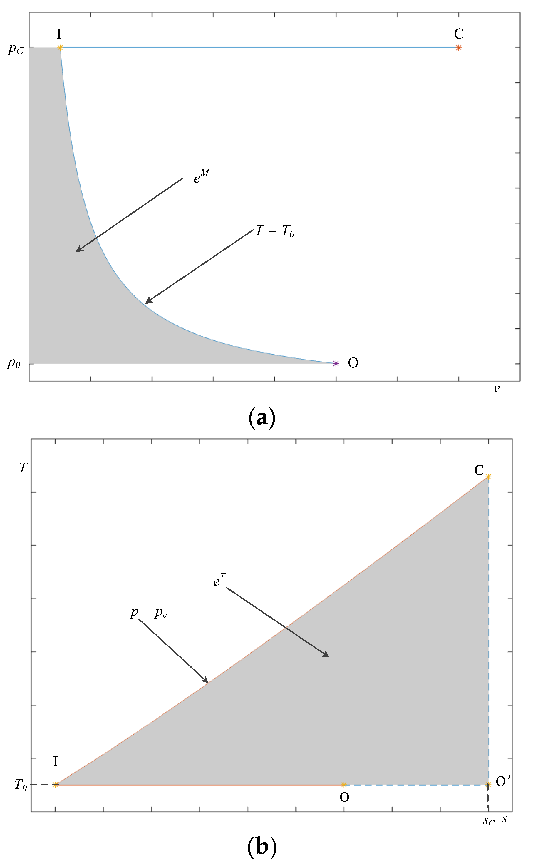
Physical exergy is due to the difference in the temperature and the pressure between the system and the environment. For a material stream with a certain temperature and pressure (point C in Figure 1) higher than those of the reference condition (point O in Figure 1), its specific physical exergy () is calculated by:
where h and s stand for specific enthalpy and specific entropy respectively; subscripts C and 0 stand for point C and reference condition respectively.
Physical exergy can then be conventionally split into the thermal part (), associated with the temperature deviation, and the mechanical part (), associated with the pressure deviation) [1]:
can be calculated along the isobar from the current state (TC, pC) to an intermediate state (T0, pC) (point I in Figure 1), that is,
or
The in Equcation (2) is calculated along the isotherm from state (T0, pC) to the referenced state (T0, p0), that is,
or
These two parts correspond to the grey area (I-O-p0-pC) on the p-v diagram in Figure 1a and the grey area (C-I-O′-C) on the T-s-diagram in Figure 1b, respectively.
The differential form of Equation (1) is:
Substituting and into Equation (5) gives:
For the ideal gas, there is:
Note that for the ideal gas, and . These conditions, together with Equation (7) give:
Meanwhile, integrating Equation (7) gives the specific physical exergy in two parts:
Equation (9) suggests that:
Considering when the pressure p is a constant, Equation (9) can be also written as:
where the can be valued as any pressure value including . Clearly, Equation (12) is the combination of Equations (3b) and (4b), which are illustrated in Figure 1. In other words, for the ideal gas:
Therefore, Equation (2) and Equations (10)–(14) together suggest that the physical exergy of the ideal gas stream can be split into two independent parts: the part represented by (or ) is dependent only on the temperature, while the other part represented by (or ) changes only with the pressure. In summary, the splitting of the physical exergy in the conventional method is rational for the ideal gas stream. However, this is not the case when the material stream involved in the analysis is not the ideal gas. Specifically, because of for a real material stream, it leads to that the “thermal” part is no longer independent of the pressure:
Consequently, Equation (8), (10) and (11) become invalid for a real material stream. In fact, the “thermal exergy” of such a fluid changes with both the temperature and the pressure. In this circumstance, the thermal exergy split calculated by Equation (3) is a function of factors more than the temperature and, thus, and it becomes more complicated than what its literal meaning indicates. Similarly, the mechanical exergy calculated by Equation (4) is incomplete because it does not include all pressure-related components. Therefore, the conventional splitting method by Equations (2)–(4b) becomes unsuitable, which makes the splitting less instructive for practical engineering problems.
Generally speaking, the “classification” of exergy should refer to the “causes” or the “effects” of the concern. In exergy analysis, the difference in the temperature and the pressure between the stream and the environment can be regarded as the causes of physical exergy, and the working ability of the stream are then considered as the effect. However, the aforementioned exergy analysis uses the “causes” as the criteria to split the physical exergy, which is not suitable for a real material stream, because Equation (8) only applies to ideal gas. For this reason, splitting the physical exergy by its “effect” is preferred. In particular, physical exergy can, in theory, be converted into useful work, although it depends heavily on the possible methods of transformation. As such, physical exergy is to be split by its feasible working ways in the current study.
3. Splitting of Physical Exergy by Its Feasible Working Ways
3.1. Splitting Principles and Potential Application
Two basic feasible working ways generally occur for a material stream, through which one directly drives mechanical devices, such as a turbine, and the other releases heat to another material stream, and the subsequent heated stream drives some working devices. To facilitate the following discussion, the first one is referred to as the “direct way”, while the second one is referred to as the “indirect way”. Correspondingly, the work produced by the direct way is named as the “direct work” and that produced by the indirect way is the “indirect work”.
The physical exergy of a material stream represents the maximum work that it can produce theoretically. However, not all of the physical exergy can be converted into work in the same way. Therefore, the physical exergy is split into three parts according to the feasible working ways including the direct exergy, the indirect exergy, and the adaptive exergy:
(1) The direct exergy, which can work only in the direct way, and the corresponding specific direct exergy is denoted as eD;
(2) The indirect exergy, which can work only in the indirect way, and the corresponding specific indirect exergy is denoted as eI;
(3) The adaptive exergy, which can work in either the direct way or the indirect way, the corresponding specific adaptive exergy is denoted as eA.
With the above definitions, the splitting of the physical exergy can then be expressed as:
It has been established that for thermal power cycles, such as the Brayton cycle, only the eD and the eA can drive turbines working. In other words, the increment in the eD and the eA plays a dominating role in increasing the working ability of the working fluid. Thus, a proportion index is introduced:
Here, represents the increment in the variable compared to the reference state, that is:
where the subscripts C and 0 represent the current and the reference state of the studied material stream, respectively, and denotes , , and . For the working fluid entering a turbine in a thermal power cycle, a larger indicates a larger proportion of the physical exergy that can be worked directly and generate electricity, which is helpful for improving the exergy efficiency of the thermal power system. From this viewpoint, F is called as the “maximum direct working proportion”.
Besides, based on the split physical exergy parts, two other indices are defined to represent the suitability of the thermal power system:
where denotes the increment in the available direct work per unit mass of the working fluid, and denotes the increment in the available direct work per unit volume. Provided that the electricity capacity of the cycle is a constant, the bigger or is, the less mass or volume of working fluid is needed. Correspondingly, the power to convey the working fluid and the size of the main equipment can be reduced, subsequently decreasing the construction and operation costs of the thermal power system.
3.2. Theoretical Analysis
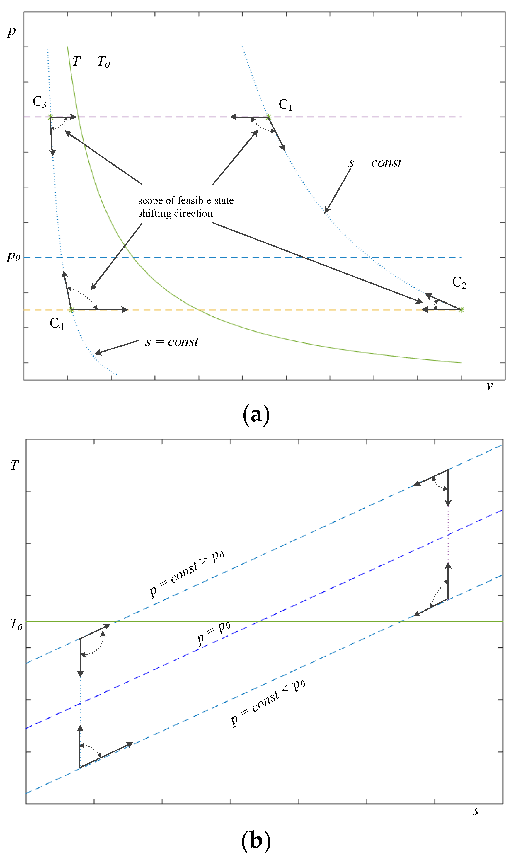
When a material stream can exchange heat only with the environment (that is, there is no other heat source existing), it will only absorb (or release) heat from (or to) the environment if its temperature is lower (or higher) than the environmental temperature. Thus:
where denotes the specific heat of the material stream. Considering that and , Equation (21a) can be rewritten as:
Correspondingly, when no other work is considered, except for those produced by the environment or the stream, the stream can only provide (or obtain) work for (or from) the environment if its pressure is higher (or lower) than the environmental pressure, that is:
In Equation (22a), denotes the technical work that the stream provides for the environment. Combing and with Equation (22a) gives:
Equations (21b) and (22b) restrict the feasible direction of the material stream spontaneously shifting between its isobar line and its isentropic line when it interacts only with environment as illustrated in Figure 2. The points C1, C2, C3, and C4, respectively, represent the four general thermodynamic states that the stream can take.
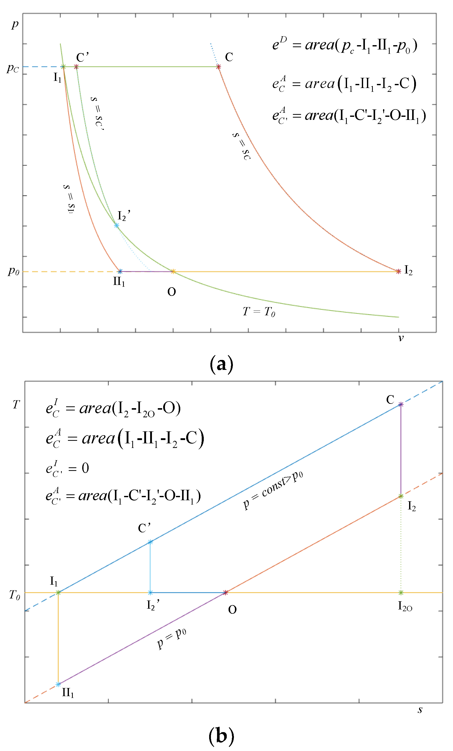
Equations (21b) and (22b), as illustrated by Figure 2, suggest that for a material stream with high temperature and high pressure (represented by point C1 in Figure 2), the possible reversible state shifting process that produces the minimum direct work should include an isobaric compression, an isentropic expansion, and an isobaric expansion. Its path is C(C′)-I1-II1-O as shown in Figure 3. The specific direct work produced by the process is represented by the area (pC-I1-II1-p0) in the p-v diagram (Figure 2a). The specific direct work (as defined in Section 3.1.) equals to the specific direct exergy of the material stream. Thus, the specific direct exergy of the stream at the thermodynamic state of point C or point C′ (as shown in Figure 3) can be presented as the area (pC-I1-II1-p0), or expressed as:
or
In Equation (23b), represents the specific entropy of the material stream with pressure and temperature , respectively. According to Figure 2a, Equations (23a) and (23b), it can be concluded that the specific direct exergy of a material stream with high temperature and high pressure is determined by its pressure, and the higher the pressure, the larger the specific direct exergy.
Figure 3 shows that when the thermodynamic state shifts along the path C(C′)-I1-II1-O for a material stream of unit mass, its physical exergy keeps decreasing until it reaches 0. The physical exergy lost in the subprocess (I1-II1) is the specific direct exergy, eD, as defined in Section 3.1, and such loss in other subprocesses equals to the sum of the specific indirect exergy, eI, and the specific adaptive exergy, eA. For the process (C(C′)-I1-II1-O), neither eI nor eA can perform work directly, but, in theory, they can be changed into work in the indirect way. The sum of eI and eA is represented as the sum of the area enclosed by C(C′)-I1-I2O(I2′) and the area enclosed by I1-II1-O inn the T-s diagram. This sum can be expressed as:
or
Equations (21b) and (22b) also suggest that the shifting path of the reversible state in the p-v-diagram and the T-s diagram to produce the maximum direct work should be C(C′)-I2(I2′)-O as shown in Figure 3. By definition, the maximum direct work produced by the material stream per unit mass equals to the sum of eD and eA of the stream. However, in order to calculate the (eD + eA) of the material stream, two situations must be considered. One is the state of point C in Figure 3, which represents the condition that the isentropic temperature of the material stream at p0 is no lower than T0, i.e.,
The other is the state of point C′ in Figure 3, of which the condition is that the isentropic temperature of the material stream at p0 is lower than T0, i.e.,
In Equations (25) and (26), is the isentropic temperature of the material stream at p0, i.e., the temperature of the material stream when its pressure decreases to p0 during the process shifting along the isentrope in the p-v-diagram and the T-s diagram.
At the state of point C corresponding to Equation (25), the sum of eD and eA is represented by the area included by pc-C-I2-p0 in the p-v-diagram, and it can be calculated by:
or
where represents the specific entropy of the material stream for the pressure of and the temperature of .
The lost specific physical exergy in the subprocess (I2-O) equals to the specific indirect exergy, which corresponds to the area enclosed by I2-I2O-O in the T-s diagram, and is expressed as:
or
Combing Equations (24a) and (28a), it gives:
Note that this equation can also be derived using Equations (23a) and (27a). Moreover, with Equations (24b) and (28b), there is:
Or by Equations (23b) and (27b), eA can be also calculated as:
In summary, at the thermodynamic state of point C which is represented as in Inquality (25), the three components of the split specific physical exergy of a material stream, namely, the specific direct exergy, the specific indirect exergy, and the specific adaptive exergy, can be calculated by the groups of Equations (23a) and (23b), Equations (28a) and (28b), and Equations (29a) and (29c), respectively.
Similarly, at the thermodynamic state of point C′ which satisfies Inequality (26), the specific indirect exergy of the material stream is 0, i.e.,
The specific adaptive exergy can be represented graphically by the area enclosed by I1-C′- I2′-O-II1 in the p-v diagram or the T-s diagram, as demonstrated in Figure 3, and calculated by any one of Equations (31a)–(31c).
3.3. Reference Condition Setting
The reference condition is the starting point of the exergy computation; hereby, it has an immediate impact on the exergy analysis. In the existing exergy analyses, the reference condition was set to be either the local environmental condition (i.e., the pressure and temperature of the local atmospheric) or the standard state (p0 = 101.325 kPa and T0 = 15 °C). In principle, these two settings do not differ significantly, especially when the system studied runs at a thermodynamic state far away from the reference condition. This makes the analysis results from different settings comparable.
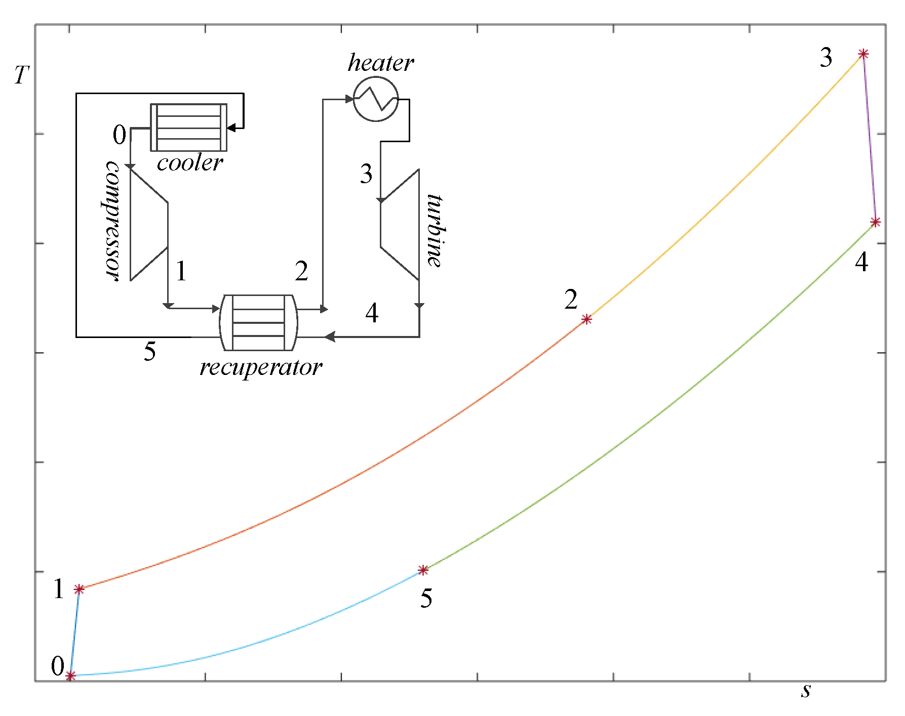
For systems interacting with the environment, for example, a vehicle engine system [15], setting the local atmospheric environment or the standard state as the reference condition is suitable. However this is not the case for systems isolated from the atmospheric environment, such as the supercritical CO2 power cycle shown in Figure 4, for such systems are often operated in thermodynamic states that are far away from the environment and have no interactions with the atmosphere unless they run out of normal conditions. Although the local environment or the standard state can still be taken as the reference conditions in these circumstances, the subsequent exergy results calculated cannot accurately reflect the working ability of the streams. For a system of this type, if what we are concerned are the system’s working characteristics and the working potentiality, it is considered to be more reasonable to select the state point that is the closest to the local environment among those experienced by the working stream and use it as the reference condition. For example, for the aforementioned supercritical CO2 power cycle, when the stream enters the compressor, the thermodynamic state is nearly under the local atmospheric environment, and this state (for example, point 0 in Figure 4) is more suitable to be used as the reference condition than the local atmospheric state. This selection helps to generate reliable results in analyzing the working characteristics of the cycle, for example, the power generation capacity per unit working fluid.
4. Applications of Splitting Method in the Exergy Analysis of the Supercritical CO2 Cycle
4.1. Simulation of the Supercritical CO2 Brayton Cycle
The supercritical carbon dioxide (s-CO2) Brayton cycle is considered one of the most promising thermal power generation cycles nowadays due to the fact of its advantages over others including simplicity, compactness, good stability, improved safety, etc. [16,17]. Several layouts of the s-CO2 cycle were developed including the simple cycle, the recompression cycle, and the preheating cycle. In the past, various efforts have been made to conduct an exergy analysis of these cycles [7,18,19,20], leading to a better understanding of these cycles. In this section, the current physical exergy splitting method is applied to the exergy analysis of an s-CO2 cycle to demonstrate the applicability of the method developed. The considered cycle (as shown in Figure 4) is a simple one but represents the basic form of complex cycles. In this cycle, the high-pressure s-CO2 at state 1 was successively heated in the recuperator and a heater; then, the heated high-pressure s-CO2 at state 3 was expanded to a lower pressure in the turbine. Part of the energy of the exit stream at state 4 was recovered in the recuperator, while the rest was rejected in the cooler. The cold and low-pressure stream was then compressed to a higher pressure at state 1. Here, part of the work produced by the turbine was used to drive the compressor.
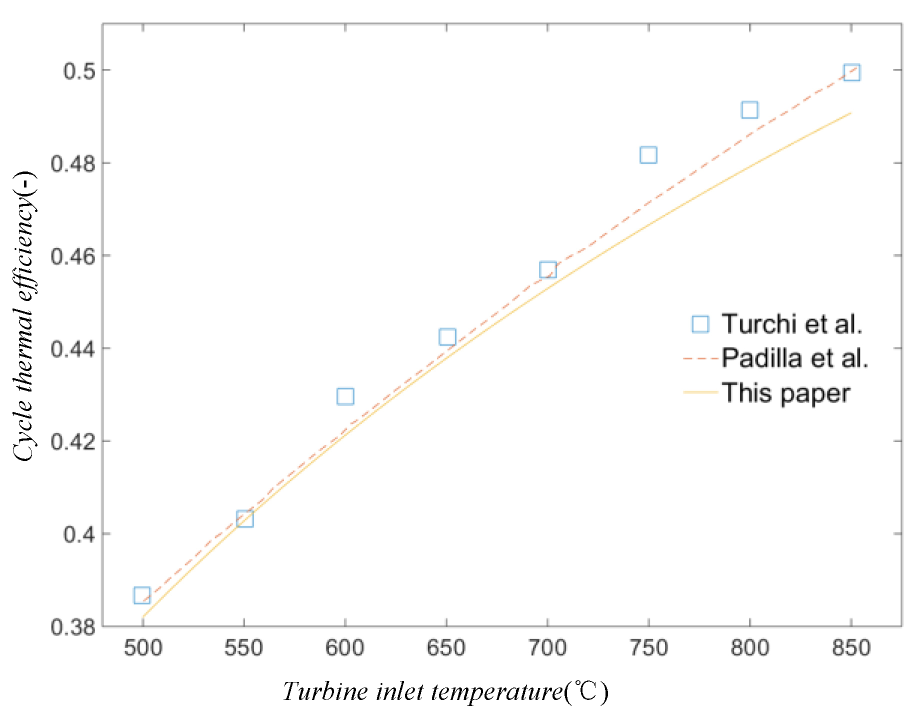
Based on the methods introduced in References [19,20], a simulation program was developed using MATLAB. The assumptions made in the simulation included: (1) the pressure remained constant in the pipes and the heat exchanger; (2) all the components were well insulated; (3) the cycle operated under steady-state conditions. This program was validated with References [19,20], and the values of the parameters listed are in Table 1. The thus calculated thermal efficiencies were compared with those obtained by the current method, and the results are shown in Figure 5. As seen from this figure, the deviations between the results calculated and that reported in literature were less than 2.0%.
4.2. Comparison of Two Exergy Splitting Methods
The exergy of a material stream usually includes four major parts: the physical exergy, the chemical exergy, the kinetic exergy, and the potential exergy. The last three can be neglected for the s-CO2 stream in the power cycle because the unique working fluid is used, and no chemical reactions occur. In these circumstances, only the physical exergy needs to be considered. Below, the physical exergy and its three split parts are calculated using the formulas given in Section 3.2.
Generally, for a s-CO2 stream, the possible working ability through the cycle is much related to the thermodynamic state, represented by point 1 (Figure 4), rather than the state of the local environmental condition. Thus, the state conditions of point 1 are set to be the reference condition in the exergy analysis. Below are the reference conditions considered in this study:
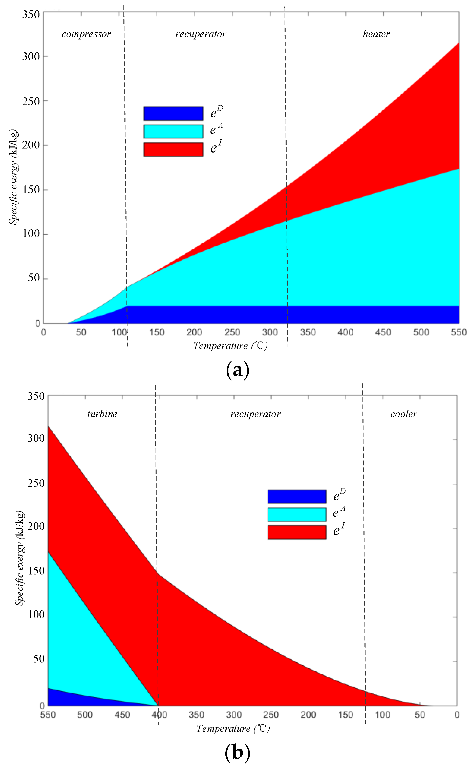
For an s-CO2 stream with a temperature of 550 °C at the inlet of the turbine, the physical exergy and the three parts defined by this paper in the cycle are shown in Figure 6. Here, the two parts (that is, the specific thermal exergy and the mechanical exergy) obtained using the conventional method are also included in Figure 7 and Figure 8 to compare them with the present results.
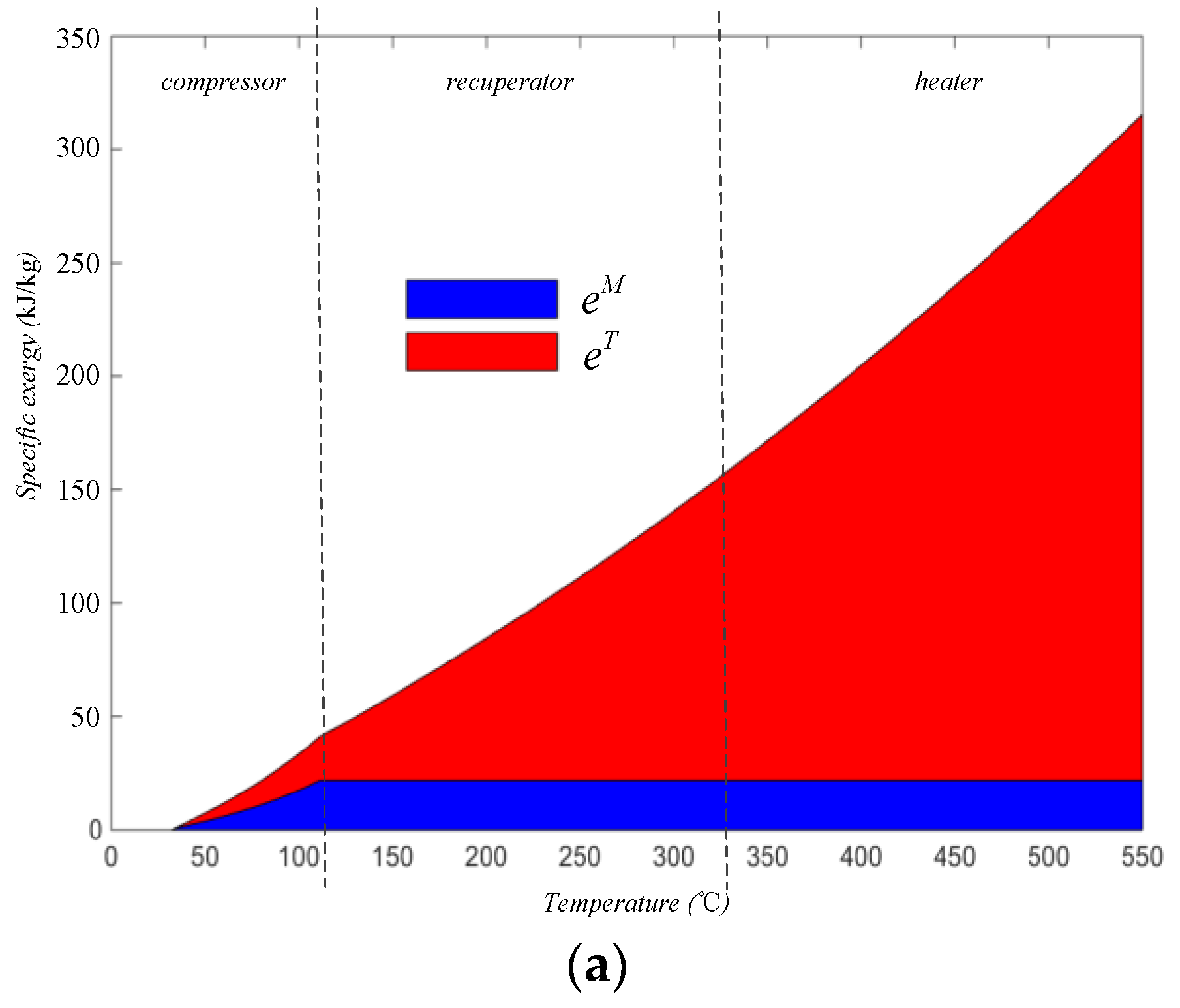
The comparison of Figure 6 and Figure 7 suggest the new splitting method provides more detailed information of the stream’s “working ability” than the conventional method. As shown in Figure 6a and Figure 7a, though the two methods all illustrate the physical exergy of the stream increasing in both the compressing process and the heating process and their qualitative results seem consistent, great differences exist in the details of the results.
Firstly, the new method developed in the study can provide more information about how the increased exergy can be used in different feasible working ways. For example, as illustrated in Figure 6a, the increased exergy in the compressing process is consisted of and , and the increased exergy in the heating process is consisted of and . As discussed previously, the increased part in the compressing process may be entirely converted into work by adopting an ideal turbine; however, this is impossible to be achieved for the part increased in the heating process. Besides, although it can be also found in Figure 7a that both and increased in the compressing process while only increased in the heating process, the difference in the increased feasible working ways of resulting from the two processes cannot be distinguished.
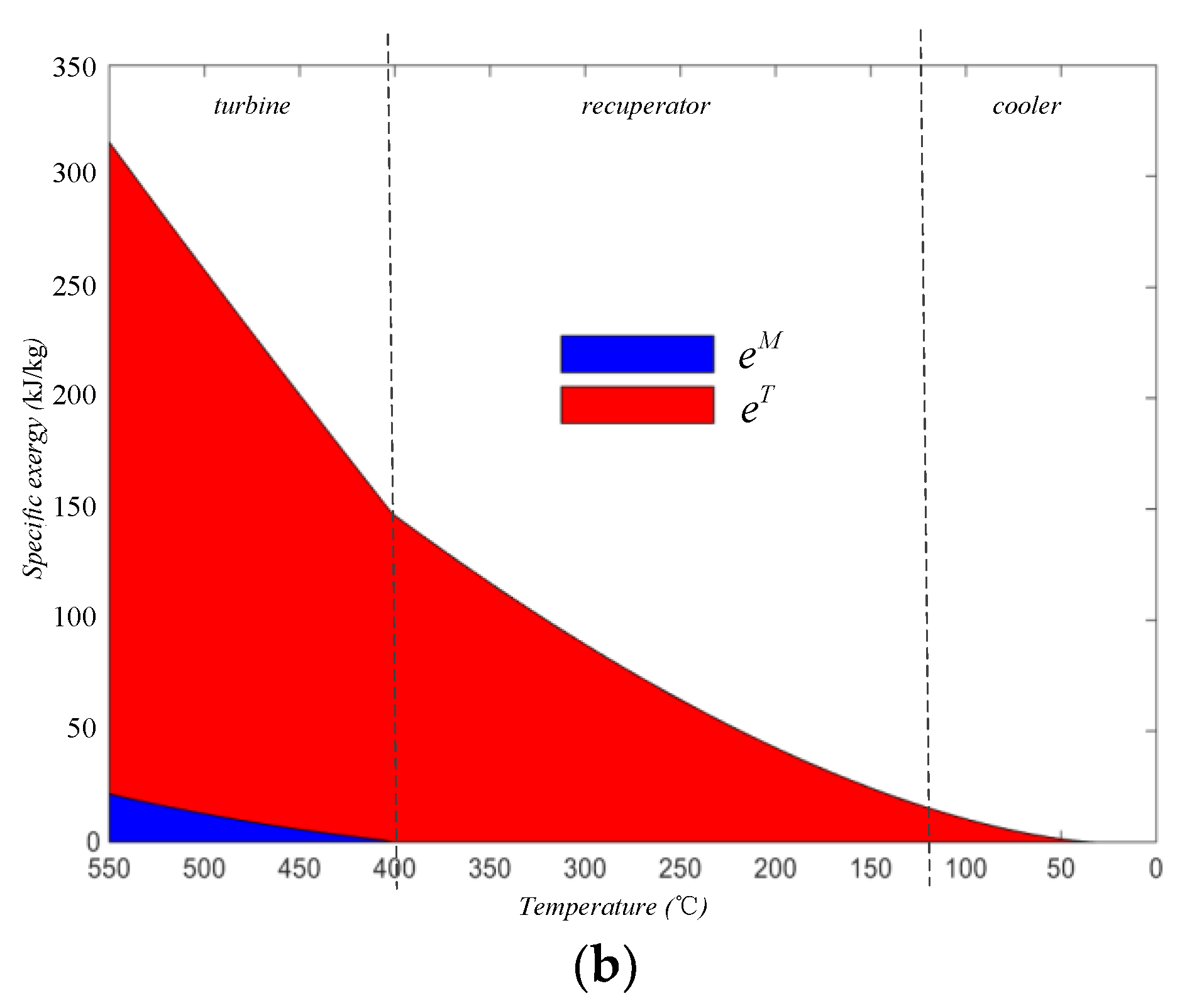
In addition, by comparing Figure 6b and Figure 7b, information can only be obtained by the method proposed in this study that the physical exergy of the stream was found to still be high when it left the turbine, and this indicates that this residual physical exergy cannot be further converted into work directly or be used to drive the turbine to work directly because it is . In contrast, using the conventional method, not only cannot these types of information be obtained, but the results in Figure 7b may even cause a misunderstanding that it is the turbine that fails to convert the thermal exergy into work efficiently.
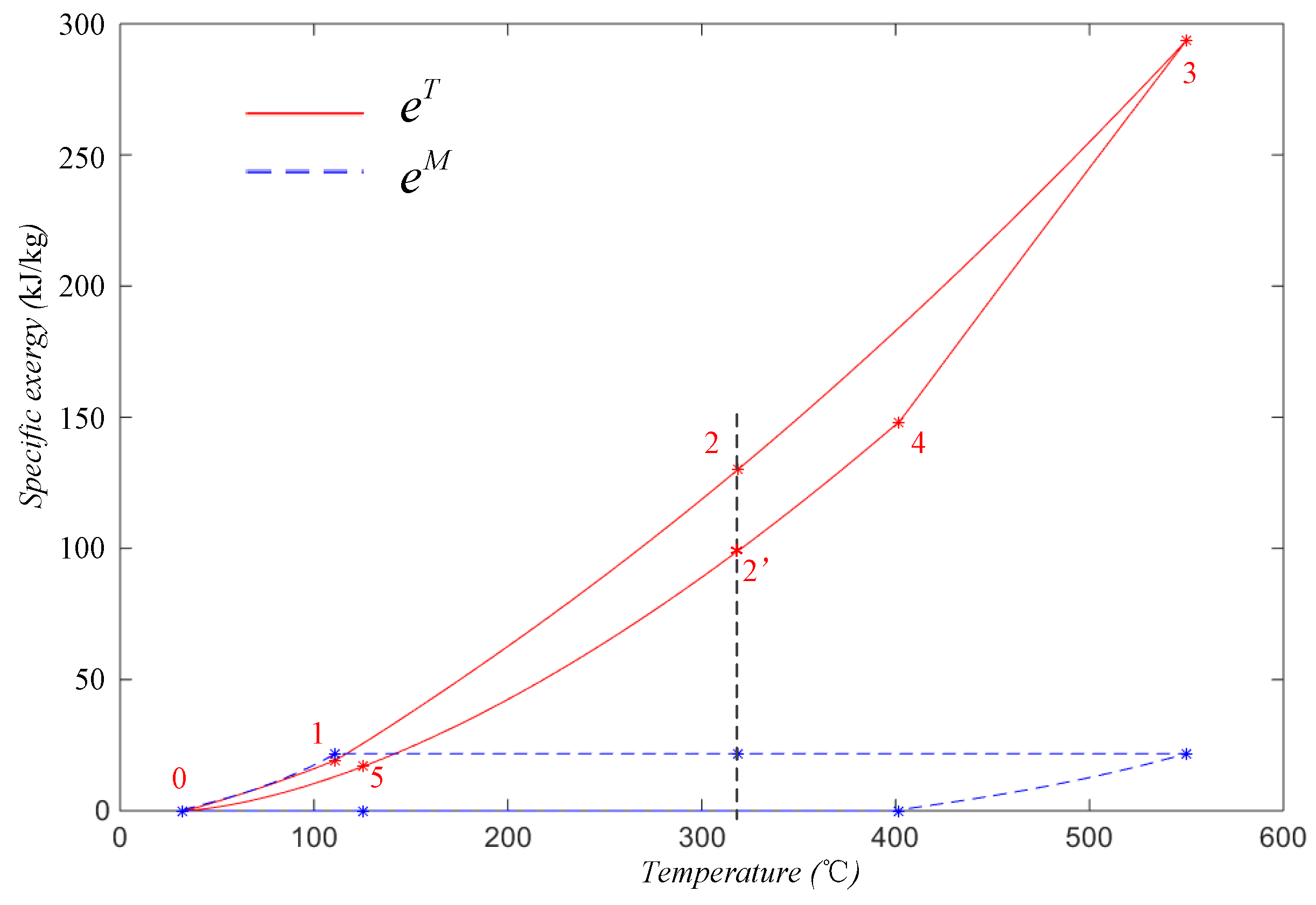
The advantages of the current method over the conventional method can be further highlighted by the results shown in Figure 8. When the stream was at different states with the same temperature but different pressures (e.g., the states representing by point 2 and point 2′ in Figure 8), the specific thermal exergy of the stream was different, which means that the thermal exergy was not only influenced by the temperature but also changed with the pressure. This result confirms the analysis in Section 2. Based on the current method, the overlap between the split parts was avoided, benefiting from dividing the physical exergy into three parts. In addition, three subsequent split exergies can be clearly defined, and their literal meanings are coincident with their physical meaning. These results cannot be achieved using the conventional method.
4.3. Exergy Splitting and Exergy Analysis for the s-CO2 Brayton Cycle
The Brayton cycle aims to convert the heat of working stream, such as s-CO2, into mechanical work. However, according to the second law of thermodynamics, not all of the heat in a stream can be converted into mechanical work. Furthermore, for the physical exergy of the stream, only the direct part and the adaptive part can be converted into turbine work. In the Brayton cycle as illustrated in Figure 4, as the s-CO2 stream was heated in the recuperator and the heater, the temperature of the stream rose from approximately 111 to 550 °C, and the specific physical exergy increased by approximately 274.0 kJ/kg. Correspondingly, the exergy () that can work directly rose by only 132.1 kJ/kg. Apparently, a considerable proportion of the increased exergy cannot work directly, and this proportion generally becomes larger as the stream temperature at the turbine inlet rises.
Figure 6 presents information on the heat energy lost in the power cycle. As shown in Figure 6b, approximately 17.0 kJ/kg of exergy was wasted in the cooler, and in the recuperator, approximately 13.1 kJ/kg of exergy was released by the hot stream, and only 11.1 kJ/kg was transformed into the cold stream. In this process, approximately 15.4% of the exergy was destructed. Figure 6 also shows that the remained constant during the entire heating process, where the stream flowed through the recuperator or the heater. Based on this understanding, Equation (17) can be rewritten for the heating process as:
More concretely, this equation can be written as:
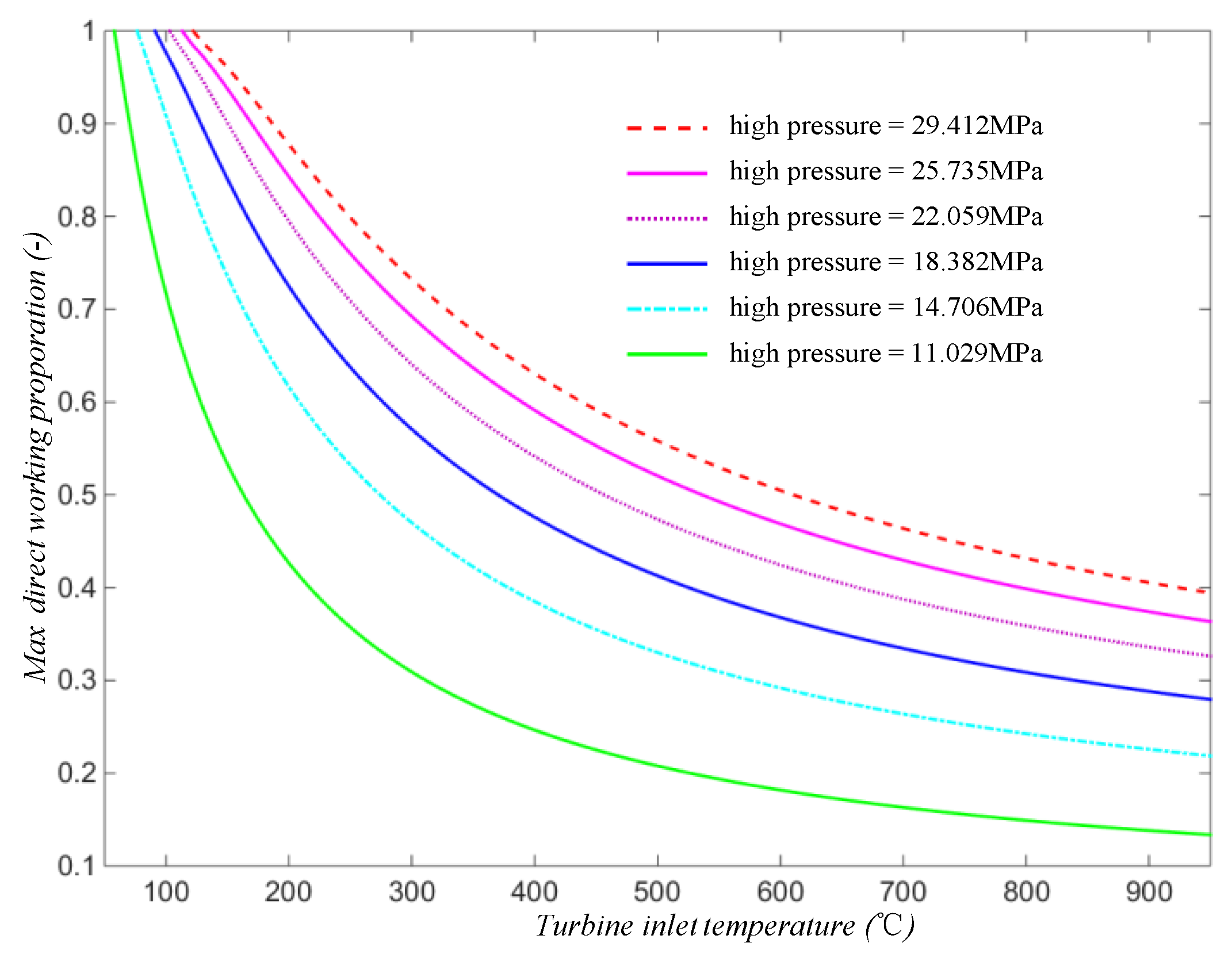
where the subscript 1 represents the thermodynamic state when the stream exits the compressor, corresponding to point 1 in Figure 4. Via Equation (35), the maximum direct working proportions of the s-CO2 stream at the turbine inlet were calculated under the conditions of different “high pressure” and “turbine inlet temperature” while keeping the other parameters constant (see Table 1), and the results are shown in Figure 9.
Figure 9 shows that by increasing the high pressure of the Brayton cycle (i.e., making the stream more compressed), the F value of the stream is increased. This result means a larger proportion of the exergy obtained in the heating process can be converted into turbine work, which helps to improve the thermal efficiency and the exergy efficiency of the cycle. Note that F changes non-linearly with the pressure. For example, at the temperature of 950 °C, F increased by 62.9% when the pressure rose from 11.029 to 14.706 MPa, but it increased by only 8.5% when the high pressure changed from 25.735 to 29.412 MPa.
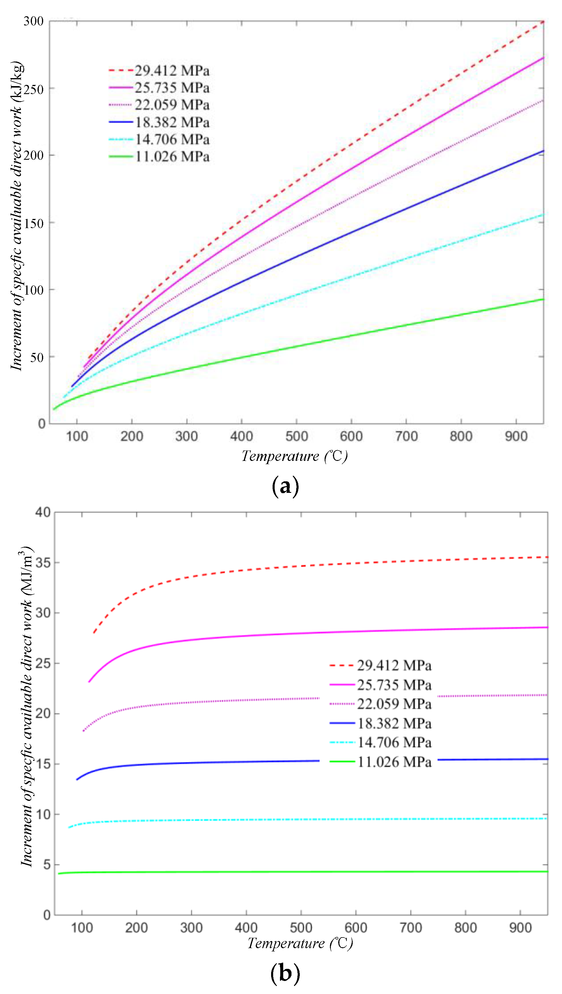
The increments in the specific available direct work, defined by Equations (19) and (20), were also obtained for the s-CO2 stream in different states as given in Figure 10. From this figure, it can be seen that both the specific generating capacity per unit mass () and the specific generating capacity per unit volume () of the working fluid increased with its pressure and temperature at the inlet of the turbine. This result means that more electricity will be generated by the cycle with equivalent or even less flow of working fluid if the pressure and/or temperature at the inlet of the turbine rises. Figure 10b also shows that the of the working fluid was more susceptible to pressure than the temperature. Therefore, to reduce the sizes of some main equipments, such as the turbine, while keeping the electricity capacity of the cycle constant, increasing the high pressure of the cycle should be more effective than increasing the turbine inlet temperature.
Figure 9 and Figure 10 show that by increasing the high pressure, it can benefit the Brayton cycle in several ways. Nevertheless, too much high pressure may create too many requirements for manufacturing and maintenance of the power system, which also means too high of a cost. Therefore, the high pressure should not be too “high” from the viewpoint of cost performance and should be controlled within a proper range.
5. Conclusions
A new splitting method of physical exergy was proposed in this paper, by which the physical exergy was split into the direct, the indirect, and the adaptive parts according to their feasible working way. Three indexes were also defined to describe the working characteristics of the working stream in a general thermal power cycle, which were:
(1) The maximum direct working proportion (F), which is the proportion of the increment of the direct work ability to the increment in the physical exergy of the stream relative to a reference state;
(2) The increment in the available direct work per unit mass (), which reflects the increment in the direct work ability of per unit mass of stream, relative to a reference state;
(3) The increment in the available direct work per unit volume (), to reflect the increment in the direct work ability of the per volume mass of stream, relative to a reference state.
The proposed method was applied in the exergy analyses of a s-CO2 Brayton cycle, and the results show that:
(1) The method proposed in the paper can provide us with more detailed information about the working characteristics of the stream, especially how much exergy obtained in the heating process can be converted into turbine work. This is an advantage that cannot be achieved using the conventional method;
(2) The three indexes proposed and defined in the paper can be used to analyze how reasonable and appropriate the cycle parameters are, such as the turbine inlet temperature and the high pressure; thus they can also be used as references for the optimization of these cycle parameters.
Author Contributions
Conceptualization, Y.S. and X.P.; methodology, Y.S. and D.G.; investigation, D.G. and Y.S.; writing—original draft preparation, D.G.; writing—review and editing, X.P., Y.S., and P.Z.; supervision, X.P.; project administration, P.Z. All authors have read and agreed to the published version of the manuscript.
Funding
This research was funded by the National Natural Science Foundations of China (grant number: 51634010), the National Natural Science Foundations of China (grant number: 51676211), and the Key Research and Development Program of Hunan Province in China (grant number: 2017SK2253).
Conflicts of Interest
The authors declare no conflict of interest.
References
- Tsatsaronis, G. Definitions and nomenclature in exergy analysis and exergoeconomics. Energy 2007, 32, 249–253. [Google Scholar] [CrossRef]
- Morosuk, T.; Tsatsaronis, G. Splitting physical exergy: Theory and application. Energy 2019, 167, 698–707. [Google Scholar] [CrossRef]
- Palazzo, P. An Extended Formulation of Physical Exergy. In Proceedings of the ASME 2010 International Mechanical Engineering Congress and Exposition, Vancouver, BC, Canada, 12–18 November 2010; Volume 5: Energy Systems Analysis, Thermodynamics and Sustainability; NanoEngineering for Energy; Engineering to Address Climate Change, Parts A and B. ASME: New York, NY, USA, 2010; pp. 559–567. [Google Scholar]
- Kelly, S.; Tsatsaronis, G.; Morosuk, T. Advanced exergetic analysis: Approaches for splitting the exergy destruction into endogenous and exogenous parts. Energy 2009, 34, 384–391. [Google Scholar] [CrossRef]
- Morosuk, T.; Tsatsaronis, G. Advanced exergy-based methods used to understand and improve energy-conversion systems. Energy 2019, 169, 238–246. [Google Scholar] [CrossRef]
- Morosuk, T.; Tsatsaronis, G. A new approach to the exergy analysis of absorption refrigeration machines. Energy 2008, 33, 890–907. [Google Scholar] [CrossRef]
- Mohammadi, Z.; Fallah, M.; Mahmoudi, S.M.S. Advanced exergy analysis of recompression supercritical CO2 cycle. Energy 2019, 178, 631–643. [Google Scholar] [CrossRef]
- Ehyaei, M.A.; Ahmadi, A.; Marc, A. Rosen Energy, exergy, economic and advanced and extended exergy analyses of a wind turbine. Energy Convers. Manag. 2019, 183, 369–381. [Google Scholar] [CrossRef]
- Bühler, F.; Nguyen, T.V.; Jensen, J.K.; Holm, F.M.; Elmegaard, B. Energy, exergy and advanced exergy analysis of a milk processing factory. Energy 2018, 162, 576–592. [Google Scholar] [CrossRef] [Green Version]
- Ebrahimi, M.; Carriveau, R.; Ting SK, D.; McGillis, A. Conventional and advanced exergy analysis of a grid connected underwater compressed air energy storage facility. Appl. Energy 2019, 242, 1198–1208. [Google Scholar] [CrossRef]
- Gholamian, E.; Hanafizadeh, P.; Ahmadi, P. Advanced exergy analysis of a carbon dioxide ammonia cascade refrigeration system. Appl. Therm. Eng. 2018, 137, 689–699. [Google Scholar] [CrossRef]
- Mortazavi, A.; Ameri, M. Conventional and advanced exergy analysis of solar flat plate air collectors. Energy 2018, 142, 277–288. [Google Scholar] [CrossRef]
- Chen, J.; Zheng, X.; Guo, G.; Luo, X.; Chen, Y.; Yang, Z. A flexible and multi-functional organic Rankine cycle system: Preliminary experimental study and advanced exergy analysis. Energy Convers. Manag. 2019, 187, 339–355. [Google Scholar] [CrossRef]
- Koroglu, T.; Sogut, O.S. Conventional and advanced exergy analyses of a marine steam power plant. Energy 2018, 163, 392–403. [Google Scholar] [CrossRef]
- Mariani, A.; Mastellone, M.L.; Morrone, B.; Prati, M.V.; Unich, A. An organic Rankine cycle bottoming a diesel engine powered passenger car. Energies 2020, 13, 314. [Google Scholar] [CrossRef] [Green Version]
- Cai, T.; Zhao, D.; Sun, Y.; Ni, S.; Li, W. Evaluation of NOx emissions characteristics in a CO2-Free micro-power system by implementing a perforated plate. Renew. Sustain. Energy Rev. 2021, 145, 111150. [Google Scholar] [CrossRef]
- Cai, T.; Zhao, D. Mitigating NOx emissions from an ammonia-fueled micro-power system with a perforated plate implemented. J. Hazard. Mater. 2021, 401, 123848. [Google Scholar] [CrossRef]
- Noaman, M.; Saade, G.; Morosuk, T.; Tsatsaronis, G. Exergoeconomic analysis applied to supercritical CO2 power systems. Energy 2019, 183, 756–765. [Google Scholar] [CrossRef]
- Padilla, R.V.; Too, Y.C.S.; Benito, R.; Stein, W. Exergetic analysis of supercritical CO2 Brayton cycles integrated with solar central receivers. Appl. Energy 2015, 148, 348–365. [Google Scholar] [CrossRef]
- Turchi, C.S.; Ma, Z.; Neises, T.W.; Wagner, M.J. Thermodynamic study of advanced supercritical carbon dioxide power cycles for concentrating solar power systems. J. Sol. Energy Eng. 2013, 135, 041007. [Google Scholar] [CrossRef]
Figure 1.
Graphic representation of specific mechanical exergy and specific thermal exergy on (a) a p-v diagram and (b) a T-s diagram.
Figure 1.
Graphic representation of specific mechanical exergy and specific thermal exergy on (a) a p-v diagram and (b) a T-s diagram.

Figure 2.
Graphic representation of the feasible shifting direction of the thermodynamic state on (a) a p-v diagram and (b) a T-s diagram.
Figure 2.
Graphic representation of the feasible shifting direction of the thermodynamic state on (a) a p-v diagram and (b) a T-s diagram.

Figure 3.
Graphic representation of the thermodynamic state shifting and exergy splitting on (a) a p-v diagram and (b) a T-s diagram.
Figure 3.
Graphic representation of the thermodynamic state shifting and exergy splitting on (a) a p-v diagram and (b) a T-s diagram.

Figure 4.
T-s diagram for a basic s-CO2 Brayton cycle.

Figure 5.
Comparison of the different methods.

Figure 6.
Specific physical exergy of an s-CO2 stream in the cycle and the three parts split by the proposed method in different regions: (a) from the compressor inlet to the heater outlet and (b) from the turbine inlet to the cooler outlet. Here, the stream temperature at the turbine inlet temperature was 550 °C.

Figure 7.
Specific physical exergy of an s-CO2 stream in the cycle and the two parts split by the conventional method in different regions, corresponding to Figure 6: (a) from the compressor inlet to the heater outlet and (b) from the turbine inlet to the cooler outlet.
Figure 7.
Specific physical exergy of an s-CO2 stream in the cycle and the two parts split by the conventional method in different regions, corresponding to Figure 6: (a) from the compressor inlet to the heater outlet and (b) from the turbine inlet to the cooler outlet.


Figure 8.
Specific mechanical exergy and specific thermal exergy of an s-CO2 stream in the cycle.

Figure 9.
Max direct working proportions of the S-CO2 stream at different system settings.

Figure 10.
Increments in the specific available direct work of the s-CO2 stream under different high pressures, calculated by (a) per unit mass and (b) per unit volume.
Figure 10.
Increments in the specific available direct work of the s-CO2 stream under different high pressures, calculated by (a) per unit mass and (b) per unit volume.


Publisher’s Note: MDPI stays neutral with regard to jurisdictional claims in published maps and institutional affiliations. |
© 2021 by the authors. Licensee MDPI, Basel, Switzerland. This article is an open access article distributed under the terms and conditions of the Creative Commons Attribution (CC BY) license (https://creativecommons.org/licenses/by/4.0/).
Share and Cite
MDPI and ACS Style
Gao, D.; Peng, X.; Song, Y.; Zhou, P. Splitting Physical Exergy by Its Feasible Working Ways. Processes 2021, 9, 2091. https://0-doi-org.brum.beds.ac.uk/10.3390/pr9112091
AMA Style
Gao D, Peng X, Song Y, Zhou P. Splitting Physical Exergy by Its Feasible Working Ways. Processes. 2021; 9(11):2091. https://0-doi-org.brum.beds.ac.uk/10.3390/pr9112091
Chicago/Turabian StyleGao, Dongbo, Xiaoqi Peng, Yanpo Song, and Ping Zhou. 2021. "Splitting Physical Exergy by Its Feasible Working Ways" Processes 9, no. 11: 2091. https://0-doi-org.brum.beds.ac.uk/10.3390/pr9112091
Note that from the first issue of 2016, this journal uses article numbers instead of page numbers. See further details here.