1. Introduction
Global warming belongs to the best-known threats to sustainable development [
1]. A reduction of greenhouse gas emissions is the way to slow it down, and this was the target to which 194 countries committed by signing the Paris Convention, with the aim to maintain global warming below the limit of an increase in the average global temperature of a maximum of two degrees Celsius. In order to achieve the objective outlined in the Paris Convention, all the countries must regularly determine their own climate objectives for 5-year periods and gradually increase them [
2,
3]. At present, the European Union, including Slovakia, is committed to achieving carbon neutrality by 2050, consisting in emitting only an amount of carbon dioxide into the atmosphere that nature can accumulate in real time or a short term. Even though the percentage of renewable energy sources on the energy market has increased, it will most probably be necessary to extend the existing energy market. One of the alternatives to an energy carrier is hydrogen [
4,
5].
Statistical data published by the International Energy Agency (IEA) indicate fossil fuels as a basic source for covering the existing hydrogen consumption. Approximately 6% of the global consumption of natural gas and approximately 2% of the global consumption of coal are used to cover the existing demand for hydrogen in various industries, currently representing approximately 70 million tonnes per year. Hydrogen produced from fossil fuels is referred to as grey hydrogen, and the production of such hydrogen contributes to global warming by releasing more than 830 million tonnes of CO
2 into the atmosphere [
2]. A method of hydrogen production that is more ecologically acceptable is the use of technologies that capture CO
2 during the production of hydrogen from fossil fuels and biomass. Such hydrogen is referred to as blue hydrogen, and according to multiple studies, it will play an important role in the industry decarbonisation [
6,
7]. This will enable the development and completion of a non-existing infrastructure for hydrogen management and will facilitate an increased demand for hydrogen on a global scale.
A special group of hydrogen-producing technologies are the devices for waste disposal by thermal processing [
8,
9]. These processes are referred to as gasification or pyrolysis and they provide two benefits: in particular, a significant reduction of non-recyclable waste and the generation of gaseous mixtures containing hydrogen in various amounts. However, this type of hydrogen cannot be categorised with absolute accuracy, because the recovery process is associated with the production of carbon oxides. Considering the existing definition of green hydrogen, this type of hydrogen cannot be classified as green. Nevertheless, the recovery of non-recyclable wastes provides great benefits for the environmental protection.
The high-temperature processing of waste in a plasma reactor is associated with the production of four products, in particular syngas, slag, alloy, and fly ash [
10,
11,
12,
13]. The weight percentages of these products depend on the type of processed waste and the boundary conditions of the waste processing. The high-temperature processing of organic wastes is characterised by the production of gaseous components, which combine to form the resulting mixture of gases, referred to as syngas (SG). The processing of inorganic wastes is characterised by the production of slag and alloy. The percentages of alloy and slag are greatly affected by the boundary conditions and reduction conditions in which a particular process of high-temperature melting runs. A decisive economic parameter for the plasma processing of wastes is the recovery of the formed products.
Gasification and melting of organic wastes in an inert atmosphere, or with the addition of a substoichiometric amount of an oxidising agent, results in the production of combustible gaseous components, such as CO, H
2, and CH
4, and their contents in syngas (SG) are significantly affected by the waste composition and the boundary conditions of the thermal process (atmosphere type, operating pressure, temperature, time, etc.) [
1,
2,
14]. Due to the high temperatures generated by a plasma arc, independently from the partial pressure of oxygen, the organic components of the waste decompose into simple gaseous compounds.
Syngas with hydrogen and carbon monoxide as the major components represents a high-quality raw material for the chemical industry, after it is cleaned of its undesired components. Furthermore, the hydrogen, contained in significant amounts in this mixture is regarded as an alternative to the fossil fuel replacement, where the resulting product after the hydrogen recovery is an environment-friendly product.
The separation of hydrogen from syngas may be carried out by applying various technologies based on the membrane separation principles or on the method of cryogenic separation of the individual gas components. The application of such technologies usually requires high amounts of energy and funds. An interesting alternative to hydrogen separation from a mixture of gases is the application of metal hydride alloys, which are capable of absorbing the hydrogen into their intermetallic structures, and this may facilitate efficient hydrogen separation from the remaining syngas components. Hydrogen gas molecules stick to the metal surface and break down into hydrogen atoms (H). The hydrogen atoms then penetrate into the interior of the metal crystal to form a new solid substance called a metal hydride. Another important precondition is that the used alloys must facilitate the removal of the remaining gaseous SG components from the working space in a pressure container, without releasing the hydrogen already stored in the metal structure, and that they do not react with the SG components and maintain the required cyclic stability.
Another important factor affecting the applicability of metal hydrides in the process of hydrogen separation from a gaseous mixture is the efficient distribution of the generated heat in the alloy’s volume. During the hydrogen absorption into an intermetallic structure of an alloy, thermal energy is generated (an exothermic process). As the temperature increases, the absorption process kinetics decreases, and the thermal field distribution becomes uneven due to the low thermal conductivity of powder materials. As a result, there are great temperature differences inside the powder alloy, and this is regarded as an undesired phenomenon. A study by Hahne and Kallweit summarised that metal hydride powders have a very low thermal conductivity, of approximately 0.5–1 W·m
−1·K
−1 [
15]. Heat accumulation and the increased thermal stress of grains in certain points within a metal hydride alloy powder may lead to changes in its crystalline lattice, and this can result in a loss of absorbability of the alloy.
The heat transfer from and to the metal hydride alloy power may be increased by installing internal heat exchangers, i.e., thermal tubes, with the heat transfer fluid flowing inside. Research on the impact of an internal heat exchanger with a circulating heat transfer fluid on the hydrogen absorption/desorption cycle in a metal hydride tank was carried out by a collective of authors led by Alok Kumar. They installed 99 evenly arranged cooling tubes inside a cylindrical metal hydride tank containing 40 kg of the LaNi
4.7Al
0.3 alloy, while water was used as the heat transfer fluid (HTF). The embedded cooling tubes were used for HTF circulation during the absorption/desorption process. The cooling tubes were aligned straight using a supporting SS316 disk located in the centre, and were welded on both ends to SS316 circular fins with a thickness of 10 mm. In the experiment, the effects of the operating parameters, such as the H
2 supply pressure, absorption/desorption temperatures, and the HTF flow rates, on the hydration and dehydration rates were studied in order to achieve the optimal operating conditions. In this experiment, changes in the HTF flow rate had a minor effect on the absorption time. The varying HTF flow rate only affected the rate of hydrogen desorption [
16]. An air-conditioning system based on metal hydrides intended for fuel cell vehicles was presented in a paper by C. Weckerle et al. The system’s metal hydride reactors were two fin reactors, each filled with approximately 1.5 kg of Hydralloy C2. A mixture of water and glycol was used as the heat transfer fluid. The absorption ran at a pressure of 35 bar, and the half-cycles were automatically switched when the FC inlet pressure reached 4.3 bar. The time-shifted valve switching of the heat transfer fluid valves at the reactor outlet may have reduced the fluid exchange loss. In this paper, the improved system efficiency was proved [
17]. Systems comprising an internal heat exchanger with the circulating heat transfer fluid installed in a metal hydride alloy were also described in a paper by Mahvash Afzal et al. [
18].
The heat removal intensification and a homogenous thermal field inside an alloy powder are often achieved by extending the heat-transfer surface area in the form of fins, which increase the heat transfer between the powder material and the heat transfer fluid [
19,
20]. An example of such an installation was described in a paper by Garrison et al., which presented two designs for a coolant tube and a cooling fin geometry. A transverse fin design and a longitudinal fin design required approximately 126 kg of hydride precursor for the studied conditions. By solving the research task, the authors came to a conclusion that in the studied hydrogen feed conditions (50 bars), a 25-fold improvement or better hydrogen storage kinetics were required to meet the technical targets for the gravimetric capacity and fill time determined by the Department of Energy [
21].
The installation of an internal heat exchanger with inlet and outlet piping for the heat transfer fluid requires welded joints. The thermal stress exerted on these welded joints and the heat exchanger structure may impose a risk of potential disturbance of the heat transfer surfaces and subsequent contamination of the metal hydrides by the coolant, and this may cause a degradation of the powder absorbability. Such a risk factor may be eliminated by employing thermal management of the tank cover and by using an internal intensifier of heat removal without any inner coolant circulation.
2. Construction of Metal Hydride Separator
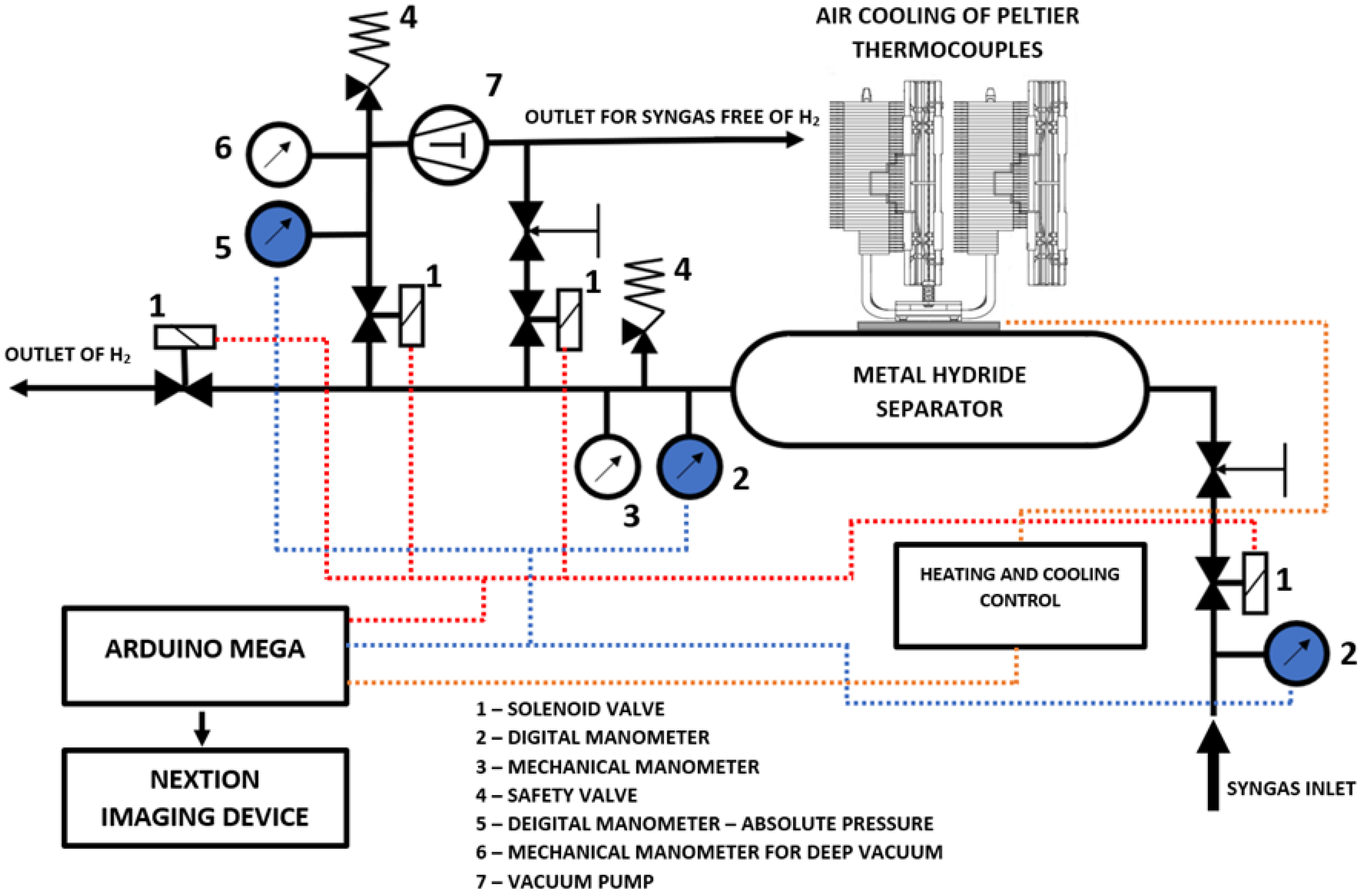
The system of a metal hydride hydrogen separator is a complex device consisting of electromagnetic valves, pressure meters, pressure vessels, and thermal management. A functional scheme and a 3-D model of the separator are shown in
Figure 1 and
Figure 2.
A digital manometer was used to measure the pressure of the gas before it entered the separator. Behind the electromagnetic valve for the syngas supply into the system, there was a reduction valve, which prevented a sudden pressure increase in the system. Subsequently, the syngas entered a metal hydride separator where the hydrogen was absorbed. As the hydrogen storage represents an exothermic reaction, the metal hydride container had to be cooled to prevent it from overheating. The external cooler consisted of a pair of Peltier Thermocouples (PTs). The heated side of the PT was cooled by a system of water coolers. Repoling the PTs facilitated the heat supply to the container for the purpose of hydrogen desorption.
After the alloy was saturated with hydrogen, the secondary syngas components, which do not absorb hydrogen, were removed. The first stage consisted of releasing the overpressure using an electromagnetic valve and the reduction armature. Subsequently, after the pressure dropped down to approximately 0.1 to 0.3 bar, the electromagnetic valve was closed, and the remaining syngas was exhausted using a vacuum pump. After the secondary gaseous components of the syngas were exhausted from the metal hydride container, hydrogen was desorbed from the alloy. The desorption pressure of the used type of metal hydride at the predefined temperature had to be lower than the pressure achieved during the vacuum exhaust of the system. The hydrogen separation cycle was accompanied by the heat generation and consumption, as is specified in more detail in the next section.
3. Heat Balance of the Separator
The hydrogen absorption and desorption ran in a metal hydride material due to changes in the alloy’s temperature. The thermal management consisted of a pair of Peltier Thermocouples located on the surface of the aluminium external heat exchangers (
Figure 3). Heat was removed from the PTs by water coolers. The heat balance of the separator may be described using the heat flow conducted via the heated syngas, heat output generated during the hydrogen absorption, heat loss through the insulation layers and heat bridges, heat flow removed by Peltier Thermocouples, and the accumulated heat flow (
Figure 3).
The correlation between individual heat flows may be expressed by an energy equation relative to a time unit:
wherein
Psh is the heat flow conducted into the separator by the syngas (W);
PG is the generated heat output in a metal hydride alloy during hydrogen absorption (W);
Phl is the heat loss of the separator (W);
PPT is the heat flow removed by Peltier Thermocouples (W); and
Pa is the thermal energy accumulated per time unit and applied when the heat flows conducted into the separator exceed the heat flows removed by cooling the PTs and the heat loss (W). If the chemical and phase changes in the syngas components are ignored, the heat flow conducted into the separator by the heat accumulated by the syngas may be identified using the following calorimetric equation:
wherein
Qm,sh is the mass flow of the syngas (kg·s
−1);
csh is the heat capacity of the syngas at a constant pressure (J·kg
−1·K
−1);
Tin,sh is the gas temperature at the inlet into the separator (K); and
Tout,sh is the gas temperature at the outlet from the separator (K).
When these metal powders absorb hydrogen to form hydrides, heat is released. The generated heat output in a metal hydride alloy during hydrogen absorption can be defined as follows:
wherein
qMH is the desorption heat of the metal hydride alloy (MJ·m
−3);
mMH is the mass of metal hydride in the separator (kg);
cH2 is the hydrogen storage capacity of the metal hydride alloy (1);
ρH2 is the density of hydrogen at a temperature of 0 °C and a pressure of 101,325 Pa (kg·m
−3); and
τ is the time (s). A certain portion of the heat flow is removed into the surrounding environment through the insulation layers of the separator; the value thereof may be identified using the following formula:
wherein
ht is the overall heat transfer coefficient, including the heat radiation (W·m
−2·K
−1);
A is the external heat transfer surface area of the separator cover (m
2);
TMHs is the surface temperature of the separator cover (K); and
Ta is the ambient temperature (K). The heat flow removed by the PTs depends on the number of the used PTs and the difference between the temperatures of the cold and hot PT panels:
wherein
n is the number of PTs installed on the separator’s surface (1);
a is the parameter following from the PT characteristics (W·K
−1);
b is the parameter following from the PT characteristics and describing the cooling power at a zero temperature difference (W);
Tc is the temperature of the cold side of the PT (K); and
Th is the temperature of the hot side of the PT (K). If the heat flows conducted into the separator exceed the heat flows caused by cooling the PTs and the heat loss, thermal energy accumulates and, consequently, the average temperature of the separator increases:
wherein Σ(
m·c) is the total thermal capacity of the separator (J·K
−1);
T is the average temperature of the separator (K); and
τ is the time (s). An analytical calculation of the heat balance using the above-specified formulas may only be carried out with an assumption that the separator temperature changes over time and does not depend on the spatial coordinates. Such an assumption would be applicable with an infinitely high thermal conductivity of a metal hydride material and a tank. With regard to the fact that the thermal conductivity of a metal hydride alloy is very low, and its value ranged from 0.5 to 1 W·m
−1·K
−1, big differences were observed in the thermal field of the separator, causing an uneven absorption and impaired heat transfer, and this reduced the overall efficiency of the separation. In order to eliminate big temperature differences in the alloy, it is appropriate to implement a heat removal intensifier into its volume; such an intensifier may be made of metal with a high thermal conductivity (e.g., aluminium). The issues regarding the heat balance of a metal hydride separator with an intensifier should be dealt with using numerical calculation methods.
4. Numerical Simulation of the Separator’s Thermal Field
In order to identify the spatial and time distribution of the temperatures of the metal hydride material in the separator, a numerical simulation was carried out in the ANSYS CFX (v19.1, ANSYS Inc., Canonsburg, PA, USA, 2018) environment. The numerical calculation was based on the following assumptions:
An exothermic reaction of hydrogen absorption was replaced in the metal hydride by a positive isotropic internal heat source;
The flow of gaseous hydrogen through the porous metal hydride powder was ignored;
A calculation of the equilibrium pressure based on the Van’t Hoff law was ignored;
The thermal conductivities and heat capacities of the used materials were constant.
Therefore, the numerical calculation was carried out while considering only solid objects, for which the heat transport may be calculated using the following heat diffusion equation:
wherein
∂T/
∂τ is the partial derivation of the temperature according to the time;
α is the thermal diffusivity (m
2·s
−1);
is the temperature gradient (K·m
−1);
qis is the internal heat source (W·m
−3);
ρ is the density (kg·m
−3); and
c is the heat capacity (J·kg
−1·K
−1). The calculation was performed for an alloy with a maximum hydrogen storage capacity of 1.43%. The hydrogen absorption time during which the heat was generated was 1200 s. The internal heat source was calculated using the following formula:
wherein
ρMH is the bulk density of the metal hydride alloy (kg·m
−3). A
qMH value was identified from the measurements described in a paper [
22]. At the interface between the surrounding air and the tank walls, the principle of the equality of heat flows near the walls was applied using the following equation:
wherein
k is the thermal conductivity of a solid material (W·m
−1·K
−1);
n is the distance in the direction of the standard line towards the interface surface (m);
h is the overall heat transfer coefficient (W·m
−2·K
−1);
Tw is the temperature of the separator wall surface (K); and
Ta is the ambient temperature (K).
A calculation was made for the 2-D geometry of an object consisting of a cylindrical tank containing a metal hydride alloy with an internal diameter of 200 mm and a wall thickness of 3 mm. The bulk density of the metal hydride material was 3000 kg·m−3; the thermal conductivity was 1 W·m−1·K−1; and the heat capacity was 430 J·kg−1·K−1. It was assumed that the maximum stored hydrogen mass capacity of 1.43% in the alloy would be reached within 1200 s. The desorption heat of the alloy was 1.01 MJ·m−3; this correlated with the internal heat source of 402 kW·m−3. In order to facilitate a comparison of the individual intensifier geometries, the cooling on the surface was set at a constant value of the heat transfer coefficient of 1000 W·m−2·K−1 and an ambient temperature of 10 °C. The initiation precondition was a constant temperature of all the tank parts, in particular 20 °C.
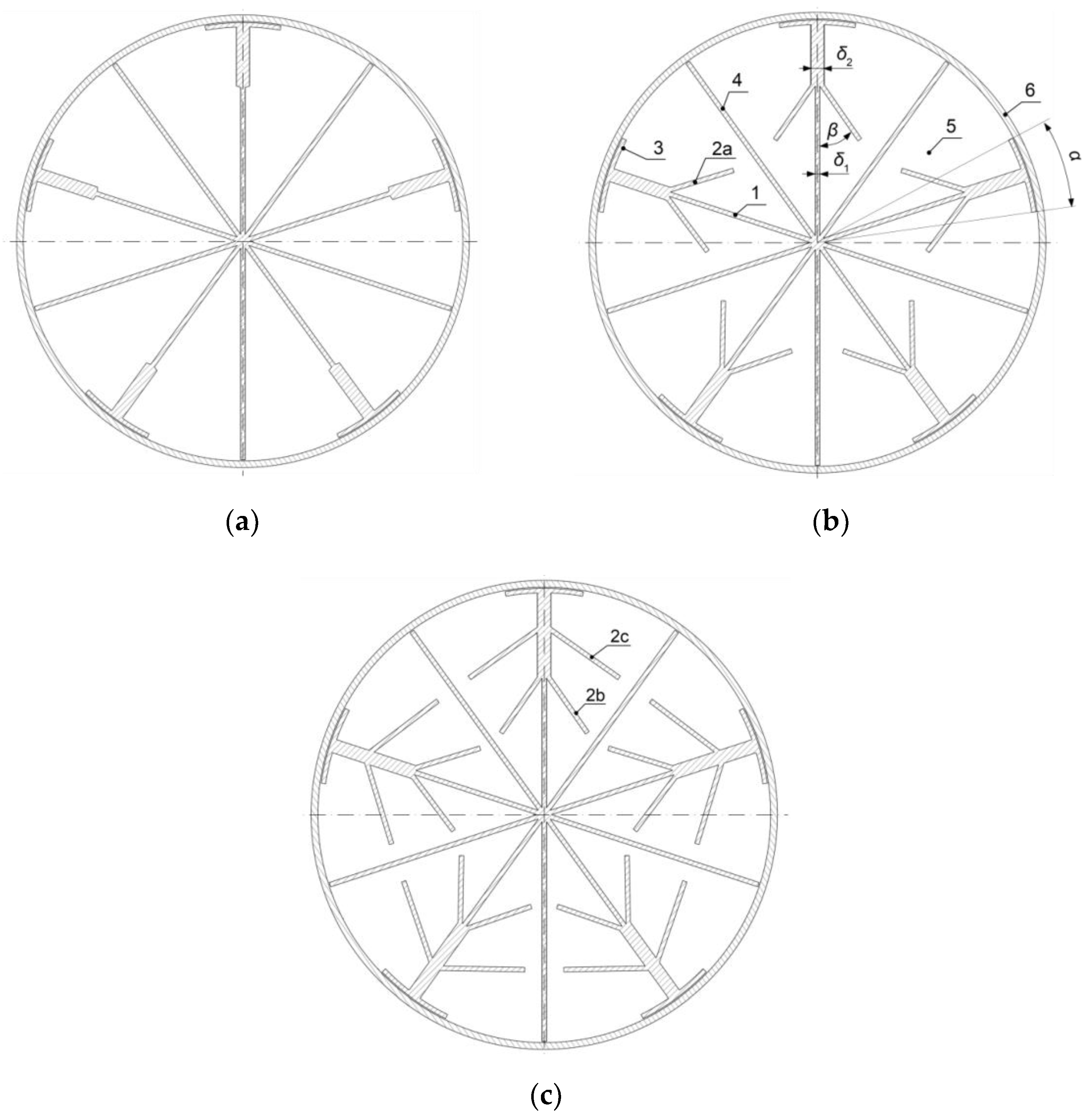
The numerical calculation was aimed at analysing the impact of the shape of an aluminium heat transfer intensifier in achieving the homogeneity of the thermal field along a cross-section of the separator for three different intensifier geometries (
Figure 4), when compared to the separator geometry without an intensifier (geometry 1). A decrease in the temperature differences in the thermal field of a powder material inside a cylindrical tank without using an internal heat exchanger containing the heat transfer fluid was achieved by implementing a passive cross-flow fin intensifier of heat transfer in powder materials, which was placed inside the cylindrical tank (item 6 in
Figure 4) without any firm attachments. The metal hydride material (item 5) was placed in the space between the intensifier and the cylindrical tank. The thermal conductivity of the aluminium intensifier was higher than the thermal conductivity of the metal hydride alloy, and this facilitated an increase of the heat transport between the powder material located near the tank axis and the cover.
The heat transfer intensifier consisted of five primary fins (item 1) and five secondary fins (item 4). In geometry 2, the primary fins were without any cross-flow fins. Geometry 3 contained a 30-mm-long cross-flow fin (item 2a), which together with the primary fin formed a 35° angle. Geometry 4 contained two cross-flow fins (items 2b and 2c), with lengths of 30 and 36 mm, which formed 35° and 55° angles with the primary fin.
The generation of heat in a metal hydride alloy was accompanied by the formation of heat-affected areas, due to increased distances between the primary and secondary fins in the radial direction. The cross-flow fins were used to balance the temperature differences in the thermal field in the central zone between the primary and secondary fins. At each primary fin terminal, there was a rounded fin (item 3) with a 20° angle (α) aimed at improving the heat transport between the primary fin and the internal surface of the tank by using a larger peripheral heat transfer surface area. In order to increase the heat transport through the primary fins, their cross-sectional area behind the first cross-flow fin in the radial direction was enlarged. The thickness of the primary, secondary, cross, and rounded fins (δ1) was 2 mm. The thickness of the primary fin behind the first cross-flow fin (δ2) was 6 mm. The rounded and the secondary fins of the intensifier were not firmly attached to the cylindrical tank, so they did not impair its integrity.
The applied numerical solution comprised the monitoring of the thermal field and heat fluxes during a period of 1200 s of the hydrogen absorption. The results of the solution are described in the next section.
5. Results
Geometry 1:
In order to compare the thermal fields, the initial stage included the creation of a numerical simulation of hydrogen absorption without an intensifier. In this case, the cross-sectional area of the metal hydride material was 3.14 × 10
−2 m
2. During the monitored period of 1200 s, hydrogen was bound with a maximum mass capacity of 1.43%. The thermal field of the separator after 1200 s is shown in
Figure 5. In this case, the low thermal conductivity of the alloy caused a significant increase in the alloy temperature along the tank’s axis. The maximum temperature was 381 °C.
The black line in
Figure 5 represents the line along which the temperature changes were measured in the radial direction. An 18° angle between the line and the vertical direction was selected, to ensure that in the other geometries (2, 3 and 4), it would cross the centre between the primary and secondary fins.
Figure 6 shows the curves of the temperature changes in the radial direction at the times of 300, 600, 900, and 1200 s.
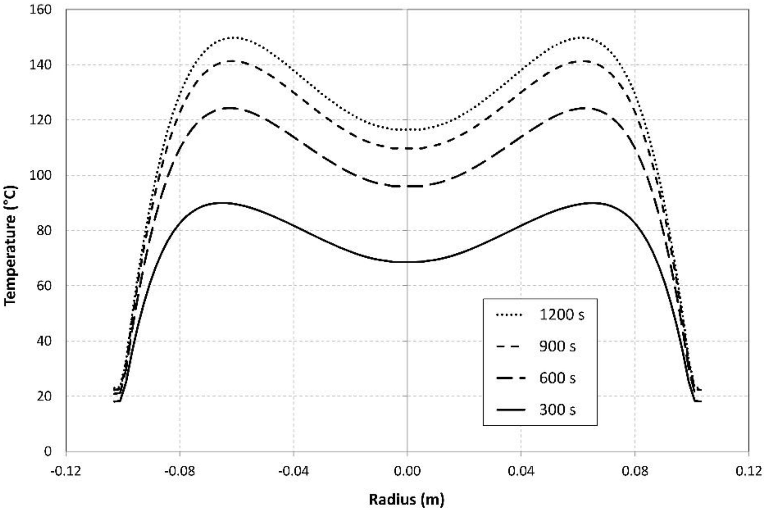
Geometry 2:
This geometry was created with an intensifier without any cross-flow fins. The cross-sectional area of the metal hydride alloy was reduced to 91% of that in geometry 1, due to the implementation of an aluminium heat transfer intensifier. As a result of the thermal conductivity of aluminium, which was 237 times higher than the thermal conductivity of the used metal hydride powder, there was a rapid decrease in the temperature of the metal hydride material after 1200 s to a value of 152 °C. The maximum temperatures shifted from the separator axis to the areas between the primary and secondary fins.
Figure 7 shows the curves of the temperature changes in the radial direction (measured on the black line in
Figure 8) at the times of 300, 600, 900, and 1200 s.
The local minimum temperature in the separator axis was caused by the evaluation line crossing the tank centre, in which the centre of the aluminium intensifier was situated.
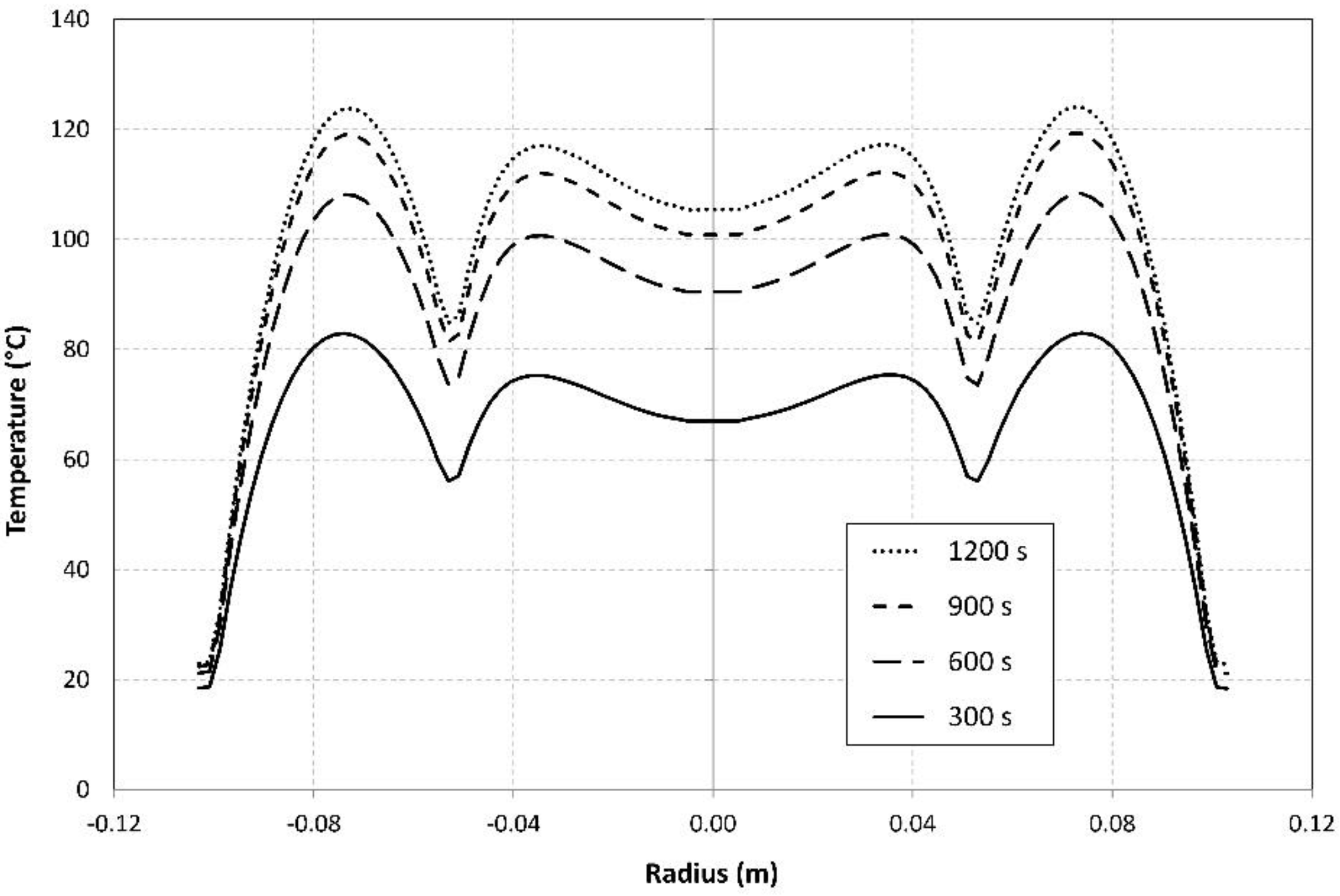
Geometry 3:
This particular geometry contained an intensifier with cross-flow fins, which extended to the temperature range of geometry 2 with the highest temperatures, and hence increased the homogeneity of the thermal field. The cross-sectional area of the metal hydride alloy was reduced down to 89% of that in geometry 1, as a result of the implementation of an aluminium heat transfer intensifier with the cross-flow fins. The addition of the cross-flow fins resulted in a decrease in the temperature in the metal hydride material at 1200 s down to 127 °C. The zone of the highest temperatures shifted over the cross-flow fins nearer to the steel cover of the separator.
Figure 9 shows the curves of the temperature changes in the radial direction (measured on the black line in
Figure 10) at the times of 300, 600, 900, and 1200 s.
The local minimum temperatures were caused by the evaluation line crossing the centre of the aluminium intensifier and its cross-flow fins.
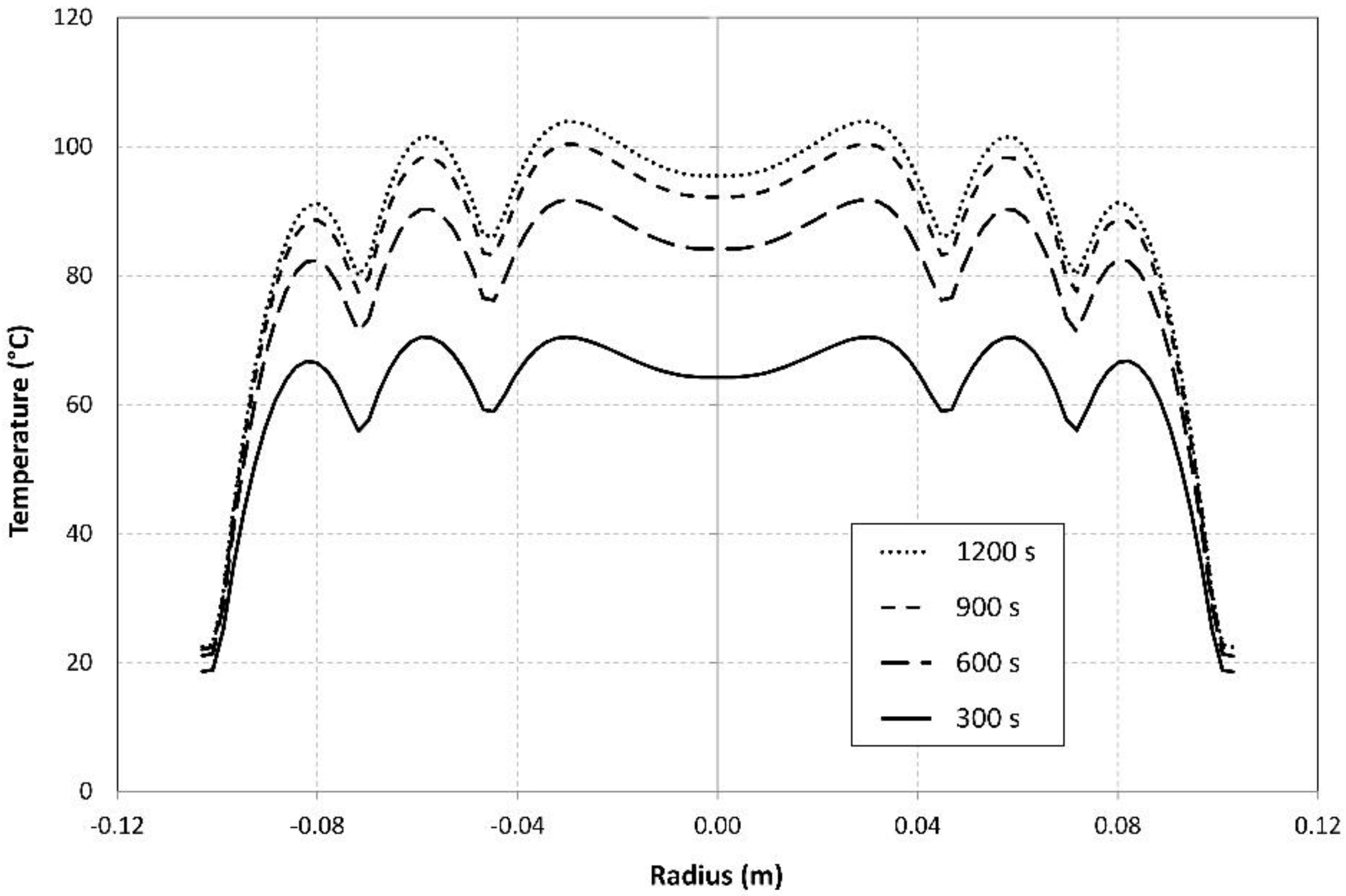
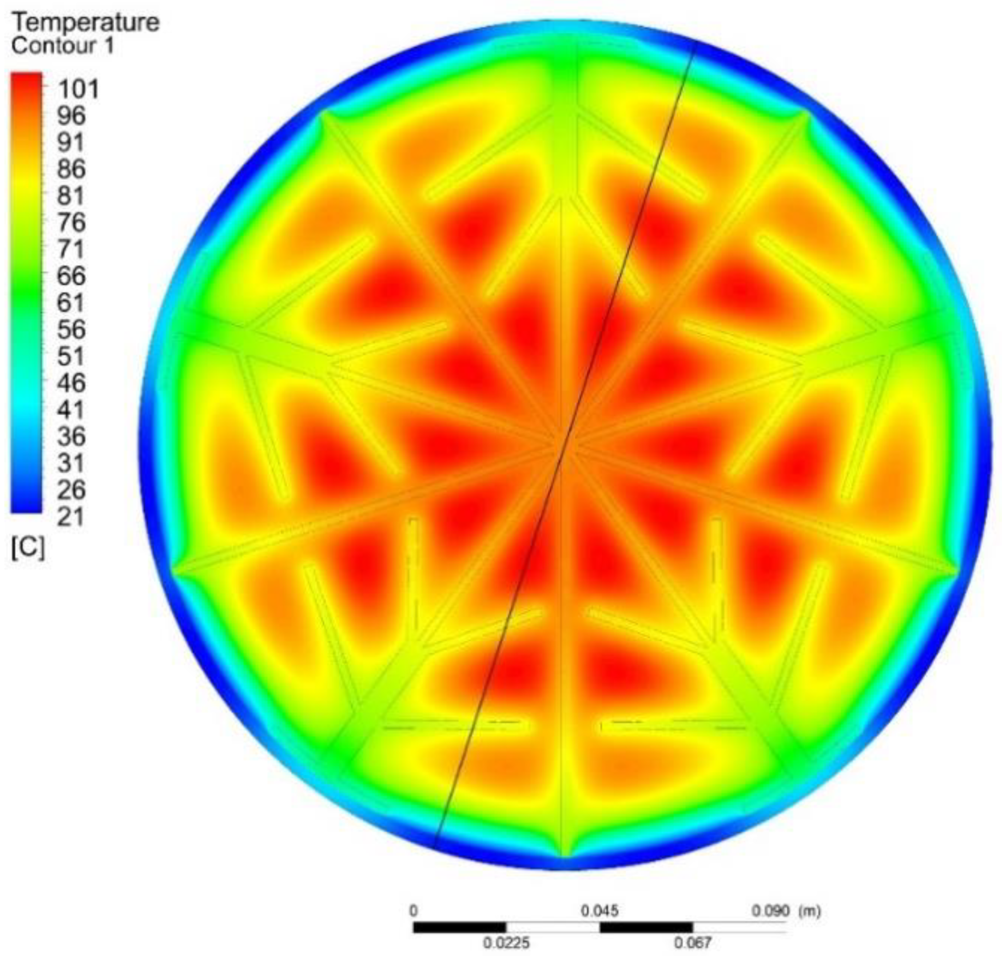
Geometry 4:
This particular geometry contained an intensifier with a pair of cross-flow fins, which extended to the temperature range of Geometry 2 with the highest temperatures, and hence further increased the homogeneity of the thermal field. The cross-sectional area of the metal hydride alloy was reduced down to 86.3% of that in geometry 1, as a result of the implementation of an aluminium heat transfer intensifier with a pair of cross-flow fins. The addition of the pair of cross-flow fins led to a decrease in the maximum temperature in the metal hydride material at 1200 s down to 104 °C.
Figure 11 shows the curves of the temperature changes in the radial direction (measured on the black line in
Figure 12) at the times of 300, 600, 900, and 1200 s.
The evaluation of the results of the numerical calculations included an analysis of the mean temperature of the metal hydride alloy. The bulk density of the alloy was set as a constant value within the entire volume; therefore, the mean temperature was calculated as an average of the temperatures of the individual elements weighed by their volumes, using the following formula:
Figure 13 shows a comparison of the curves of the mean temperatures of the metal hydride alloy for the individual geometries, as they changed over time.
The curves of the mean temperatures clearly indicate a dramatic decrease in the mean temperature where an intensifier was used, as it caused an increase in the heat transport in the separator from the core of the metal hydride material to the steel cover area, from where it passed through the external heat transfer surface into the surrounding environment.
Figure 14 shows the curves of the heat fluxes, relative to the separator length, from the separator surface towards the surrounding environment with the employed cooling.
The use of a heat transfer intensifier in the selected geometries significantly intensified the heat removal.
6. Discussion
A separator using a metal hydride alloy facilitated the hydrogen absorption from syngas, while a decisive factor of improving the process kinetics was the highest possible heat removal from the surface of the metal cover of the tank. A significant increase in the cooling heat flux was achieved by employing an aluminium intensifier, with the thermal conductivity significantly higher than the thermal conductivity of the metal hydride powder. Furthermore, the intensifiers significantly reduced the maximum temperature of the metal hydride alloy. A comparison of the masses of the metal hydride alloy relative to the mass in geometry 1, maximum and minimum temperatures reached in the metal hydride powder, and the linear heat fluxes from the separator surface to the surrounding environment at the time of 1200 s is presented in
Table 1.
Despite the percentage decreases in the metal hydride mass in the individual geometries, which also corresponded to lower amounts of the generated heat, the use of the three types of intensifiers resulted in an increase in the linear heat flux relative to 1 m of the separator length. In the cases of geometries 2 and 3, there was a 49.3% increase in the linear heat flux. With geometry 4, the increase represented 45.2%. The increase in the linear heat flux was affected by the primary and secondary fins. The application of the cross-flow fins did not increase the removal of heat through the jacket; nevertheless, it positively affected the homogeneity of the metal hydride thermal field.
An analysis of the temperature gradient Δt between the maximum and minimum temperatures of the metal hydride alloy revealed that geometry 2 exhibited a 64% decrease, when compared to Δt in the alloy with geometry 1. With geometry 3, the decrease in the temperature gradient Δt amounted to 71% and with geometry 4 as much as 77%. With geometry 2, the amount of the stored hydrogen was 9% smaller than the amount stored with geometry 1. With geometry 3, the decrease amounted to 10.9%; and with geometry 4, the amount of the stored hydrogen was 13.7% smaller. However, a positive effect of the increase in a linear heat flux and of a better temperature distribution within the thermal field significantly exceeds the decrease in the capacity of the stored hydrogen, which was caused by the application of the intensifier. Apparently, the most optimal shape of the intensifier for maximising the linear heat flux was geometry 3. Where the required outcome is to achieve a minimum temperature difference, the optimal alternative is geometry 4, as it facilitated the reduction of the total generated heat in the metal hydride volume; as a result, the internal heat source was 3.1% smaller than that in geometry 3.
The data clearly show that heat intensifiers installed in tanks and separators significantly improve the homogeneity of the thermal field, and this increases the kinetics of the hydrogen absorption and desorption processes and prevents potential changes in the crystalline structures caused by high temperatures, and improves the heat removal while the tank cover is cooled.
The research on a possibility to separate hydrogen from a mixture of various gaseous components includes the examination of the effects of the basic gas components (CO2, CO, CH4, N2, and H2) on the metal hydride properties. Due to the high percentage contents of carbon oxides in the syngas, which may amount to more than 50% of the total volume of the syngas produced during the waste gasification, it is important to investigate their effects on the degradation of the metal hydride. The degradation will depend not only on the metal hydride composition, but also on a maximum temperature of the alloy generated during the absorption process. The elimination of temperature differences in the metal hydride volume, as well as the improved homogeneity of the metal hydride thermal field, reduces the risk of catalytic reactions between the individual gas mixture components and the metal hydride components. This goal may be achieved by installing the intensifiers of the heat transfer from the metal hydride volume.
The ongoing research on the efficient removal of the generated heat from the metal hydride volume is carried out simultaneously with the investigation, production, and testing of metal hydrides that exhibit a higher resistance to the degradation caused by the presence of carbon oxides in the mixture of gases. Such metal hydrides will be presented to the public over the next few years. Furthermore, the accompanying benefit consists in the designs of novel systems facilitating a rapid reduction of the contents of carbon oxides in the mixture of gases, which enters the process of hydrogen separation carried out with the use of metal hydrides. Such systems may be based on the chemical or gravitational principles.
7. Conclusions
Hydrogen production and a concurrent waste recovery by applying thermal processes represent one of the alternative methods of mitigating the environmental impact of human activities. The hydrogen separation from a mixture of syngas generated during the plasma gasification of non-recyclable or hazardous wastes facilitates an energy carrier to be obtained in form of hydrogen, which is CO2 neutral when further processed. In addition to the above-mentioned benefits, another benefit of the thermal recovery of non-recyclable or hazardous wastes is a dramatic reduction of the original amount of wastes and a potential for the recovery of the alloys and glassy slag produced in the incineration process.
An alternative to the current methods of hydrogen separation from a mixture of gases is the use of metal hydride alloys in the process of the hydrogen separation from gaseous mixtures. Hydrogen absorption into the structure of an alloy powder is a promising method of generating high-purity hydrogen, which will be beneficial for the hydrogen management.
As has been noted in other research areas, the hydrogen separation from a mixture of gases using metal hydride alloys is also associated with certain challenges regarding the elimination of its drawbacks. In addition to the potential contamination of a metal hydride alloy by secondary syngas components, which may significantly affect the operating parameters of metal hydride alloys, it is also necessary to solve the problem related to the removal of the heat generated during the absorption from a metal hydride alloy.
The process of designing the individual separator components requires an optimisation of the separator tank in terms of increasing the homogeneity of the thermal field. When heating and cooling of the tank cover is employed, it is necessary to intensify the heat removal due to the low thermal conductivity of the alloy. This may be achieved by using heat transfer intensifiers, which facilitate a significant reduction of the difference between the maximum and minimum temperatures in the metal hydride alloy, and this will also significantly improve the thermal field homogeneity. This section is not mandatory but can be added to the manuscript if the discussion is unusually long or complex.


 ,
, 


