
Evaluating the Performance of Water Chillers Equipped with Constant- or Variable-Frequency Centrifugal Compressors


Department of Refrigeration, Air Conditioning and Energy Engineering, National Chin-Yi University of Technology, No.57, Sec. 2, Zhongshan Rd., Taiping Dist., Taichung 411030, Taiwan
*
Author to whom correspondence should be addressed.
Processes 2021, 9(6), 1039; https://0-doi-org.brum.beds.ac.uk/10.3390/pr9061039
Submission received: 12 March 2021
/
Revised: 30 May 2021
/
Accepted: 11 June 2021
/
Published: 14 June 2021
(This article belongs to the Special Issue Emerging Technologies in Heating, Ventilation, Air Conditioning and Refrigeration (HVAC&R) Systems)
Abstract
:The cooling coefficient of performance (COPR) and energy efficiency ratio (EER) of refrigerant R-134a compressors (single- and double-compressors) with different refrigerant tonnage (200, 250, 300, 380, 500, and 700 RT) for centrifugal and Maglev centrifugal compressors change with different operating performance load percentages (10–100%), and constant-frequency and variable-frequency operation, resulting in performance differences. In particular, a water chiller can have a fixed cooling water inlet temperature of 32 °C and a variable cooling water inlet temperature between 18.33 °C and 32 °C. According to the actual test results, the commercial performance code program and parameter table of the water chiller were established. Based on the performance matching of different load chillers, the on-site load capacity was analyzed and the effective water chiller performance and model matching were determined as the best choice for the tonR number of the deicing machine and unit matching, providing a reference for a future large water chiller that cannot be used on site for a single unit tonR. To achieve energy-saving benefits, different types of compressors, different refrigeration tonR operation, constant-frequency unit and variable-frequency unit alternate operation, and different operating performance load percentage operation can be allocated. Finally, the results show that, when the cooling water inlet temperature is fixed, the Maglev variable-frequency centrifugal compressor water chiller is better than the constant-frequency centrifugal water chiller, and also better than the variable-frequency centrifugal water chiller. The larger the freezing tonR of the variable-frequency centrifugal water chiller, the smaller the difference between COPR and EER. When the cooling water inlet temperature changes, the Maglev variable-frequency centrifugal water chiller is better than the constant-frequency centrifugal water chiller, and it is also better than the variable-frequency centrifugal water chiller. The larger the freezing tonR of the variable-frequency centrifugal water chiller, the smaller the difference between COPR and EER. Moreover, the operating performance of the constant-frequency centrifugal water chiller is between 60% and 90%, which can maintain relatively high COPR and EER values. The operating performance of the variable-frequency centrifugal water chiller is between 40% and 70%, which can maintain relatively high COPR and EER values. Compared with the constant-frequency and variable-frequency, the Maglev variable-frequency centrifugal water chiller can maintain higher COPR and EER values when the operating performance is between 10% and 100%. When the operating performance is between 10% and 70%, it can maintain very high COPR and EER values. When the water chiller is selected in the field, the energy-saving of COPR and EER will be given priority. Therefore, the load capacity can be used to effectively manage the water chiller performance and model selection, so that the operation performance can reach the best percentage and energy saving can be achieved.
1. Introduction
In Taiwan, air conditioning, temperature, and humidity control are essential for people’s daily needs and for restaurants, stores, medical institutions, commercial buildings, supermarkets, industrial plants, and high-technology electronics. According to the energy saving technical manual of the Bureau of Energy of Ministry of Economic Affairs of Taiwan [1,2], the proportion of power consumption for air conditioning equipment in buildings is about 23–56%. If people’s daily air conditioning use is not included, the proportion is about 45–56%, which shows that the central air conditioning system is the most energy-consuming piece of equipment in most buildings. According to the statistics of the Taiwan Power Company, the peak power consumption of air conditioning equipment in summer accounts for about 35% of the total power consumption in Taiwan. Therefore, the proportion of power consumption of air conditioning equipment in the summer is quite high in Taiwan. Among the different types of air conditioning equipment, the power consumption of the chiller compressor is the highest, accounting for about 50–60% of the total air conditioning system. Reducing the power consumption of chiller compressors while also improving their operational efficiency has become an important energy-saving direction; this must be done in such a way that the operation mode and the option to use the main carrier or a standby carrier can be adjusted at appropriate times, the operation mode strategy can be applied, and the chiller can be allocated based on the best operation load data to keep the chiller in a high-efficiency operation state.
The chiller is one of the most energy-consuming types of air conditioning equipment and often faces problems of overdesign and unnecessary energy consumption due to inadequate maintenance [3]. Analyzing the characteristics of the chiller in relation to the needs of the place where it will be used can help determine the appropriate collocation before purchase, and, after the completion of the construction, ensure that the chiller can be used according to its characteristics to maintain its performance integrity and greatly increase its energy-saving benefit. The cooling coefficient of performance (COPR) and energy efficiency ratio (EER) of the chiller are analyzed. The data of different refrigeration capacities of the centrifugal chiller are calculated using simulation consumer software. Based on different operating percentages and fixed- or variable-cooling water inlet temperature, the energy-saving benefits of the chiller that will greatly increase COPR and EER are discussed. The results of the numerical analysis of different chillers’ refrigeration capacity are used to determine the most favorable operation mode and achieve low-energy consumption and a high-efficiency method. Liu [4] found that the chiller and the motor of the auxiliary equipment of the air conditioner account for most of the power consumption of the central air conditioning system.
In recent years, the best energy-saving solution has been to install a frequency converter to control the motor speed and adapt to load change. Chen et al. [5] investigated the energy-saving and carbon reduction implementation plan for an air conditioning chiller, which accounts for a large proportion of energy consumption, and determined that replacing old equipment with new equipment is easy and that selecting a high-efficiency refrigerant compressor is very important for reducing energy consumption. If budgets are not sufficient to replace the old energy-consuming equipment, a certain degree of energy-saving can be achieved by making appropriate adjustments and planning for the existing systems and equipment. Yang [6] found that the air conditioning power consumption of general office buildings accounts for the largest proportion of the total power consumption, among which the ice water host had the highest power consumption. The performance of each chiller will be different after a period of chiller operation due to the operation time, maintenance situation, and other factors, such that a feasible chiller operation strategy must be adopted for energy saving. Chang et al. [7] found that, in addition to integrating the Maglev compressor technology, the Maglev centrifugal chiller needs to construct a complete intelligent control logic for a wide area load change and an optimized control scheme for system energy distribution (chiller, water pump, and air side) to fully utilize the advantages of oil-free Maglev direct drive. Lin et al. [8] found that the centrifugal machine using ball bearing needs an oil lubrication system, such that the refrigerant system inevitably contains a certain proportion of lubricating oil, which reduces the heat transfer effect of the heat exchanger, reduces the working efficiency of the chiller, and further increases the complexity of the compressor host. Therefore, the application of centrifugal compressors in chillers has gradually developed toward being oil-free.
Chen et al. [9] asserted that the compressor is the core of air conditioning equipment. Among all kinds of compressors, the Maglev centrifugal compressor is oil-free and has a long service life, low noise, and high energy efficiency. Therefore, the application of Maglev centrifugal compressors in air conditioning equipment will be a future development trend in the air conditioning industry.
Wang [10] states that the chiller must maintain a high-efficiency operation standard under 75–50% operation conditions, in addition to full-load operation, because the ASHRAE has an integrated part-load value for the centrifugal water chiller used in building air conditioning. According to the evaluation, the weight of 100% full-load operation of the chiller is only 0.01. When the load changes, the air conditioning demand determines whether the chiller load increases or decreases and a frequency converter can be installed for energy saving during continuous operation throughout the year.
Yu et al. [11] explored how large shopping malls replace traditional chillers with oil-free variable-frequency chillers, using the high COPR of the oil-free variable-frequency chiller to save electricity and energy. After one year of operation, the total power consumption using the oil-free variable-frequency chiller is reduced by 9.6%. Liu et al. [12] analyzed the performance difference between variable- and constant-frequency chillers through the capacity control modes and operation data of different operating loads. The experiment showed that the efficiency of the constant-frequency chiller is higher than that of the variable-frequency chiller except for during full-load operation, and the performance of the variable-frequency chiller is better than that of the constant-frequency chiller when operating with a part-load.
Chen [13] found that the variable-frequency chiller can achieve a better energy-saving effect operating with a part-load and lower cooling water inlet temperature. The climate temperature of different regions also directly affects the energy-saving effect of the chiller operation. Chen [14] states that the operation efficiency of the constant-frequency host is higher than that of the variable-frequency host when the inlet water temperature of the cooling water is high. Constant- and variable-frequency host matching can be selected for the chiller, which can obtain a higher energy-saving effect. Cheng et al. [15] studied the proper monitoring and maintenance of the chiller using complete analysis and found that standard operating procedures can reduce the probability of refrigerant leakage, reduce the occurrence of surges in the centrifugal compressor, save operating costs, and extend the service life of the chiller. Yeh et al. [16] analyzed the operation value and energy consumption performance of a single 700 RT chiller and two 350 RT chillers. They found that the operation performance of two 350 RT chillers is better than that of a single 700 RT chiller.
Refrigeration and air conditioning-related equipment have many motors and mechanical components. In recent years, Maglev variable-frequency centrifugal compressors have been used to replace the traditional centrifugal compressors, which reduces the wear on the bearing and the volume of the traditional centrifugal compressor, removes the high- and low-speed gear of the compressor wheel assembly, improves the operation efficiency, and makes the centrifugal compressor an oil-free development stage. Variable-frequency converters have also been installed to change power frequency and reduce energy consumption. Lissandrin et al. [17] focused on the efficient operation of variable-speed air-condensed chillers with variable-speed centrifugal compressors paired with (oil-free) magnetic bearings. Multiple operating conditions, at any moment in time, together with wide cooling ranges and potentially high energy efficiencies during off-peak demands create the need for an open-loop energy optimization strategy via an efficiency-based fitness function. It is solved by means of an ad hoc hybrid algorithm that combines a deterministic method and a stochastic one. The results of the simulations, which are based on two chiller layouts, show the potential of this approach.
Zhang et al. [18] analyzed some production and energy efficiency standards of water chillers, including AHRI 551/591, ASHRAE 90.1, EN 14825, EN 14511, GB/T 18430.1, GB/T 25127.1, GB/T 25127.2, GB 19577, etc. A series of highly energy-efficient water chiller technologies are introduced, including new compressor technology, high-efficiency heat exchange technology, new refrigerant technology, system energy conservation technology, high-temperature water chiller technology, and water chiller and natural cold source cooling technology in a data center. Based on the application of these technologies, the component energy efficiency, unit energy efficiency, and system energy efficiency of water chillers will improve significantly. In Deng et al. [19], a magnetic bearing centrifugal chiller (MBCC) with variable-speed control, also known as an oil-free chiller, is highly recommended by manufacturers as a remarkable energy-efficient solution for space cooling in buildings. MBCCs performed much more efficiently especially at a part-load cooling demand ratio and partial compression demand ratio. To fully take advantage of MBCCs for truly energy-efficient operation, MBCC design and operation must be optimized based on annual hourly simulation of the cooling demand and compression demand ratio rather than just focusing on the nominally rated conditions of chillers. Based on the time-series operational data log, an empirical model of MBCC was conducted that can help to optimize chiller plant design and operational strategy through annual hourly simulation of the energy performance of MBCCs.
Al-Badri et al. [20] studied the stability and performance of a water chiller system equipped with a variable speed compressor and an electronic expansion valve. The application of an appropriate control method, rather than the type of controller, may have a significant influence on the coefficient of performance and system stability. An operation with fixed superheat setting yields a lower coefficient of performance compared to the single-loop and two-loop control methods.
In comparison to the PI and PID controllers, the proportional fuzzy controller reduces the degree of superheat fluctuation. The single-loop control method produces the maximum coefficient of performance as well as good stability for both the degree of superheat and the product water temperature. Compared to the constant degree of superheat operation, the single-loop control method enhanced the coefficient of performance by 27.5%, 18.3%, and 19.7% for the proportional fuzzy, PID, and PI controllers, respectively. Catrini et al. [21] explained that multiple-chiller systems represent viable solutions for medium/large-scale air conditioning applications characterized by variable cooling demand. The energy efficiency of such systems is influenced by the number of chillers, the combination of cooling capacities, and the load-sharing among the units. The exergy economic cost of chilled water was reduced by about 7% and 30% when passing from evenly to unevenly sized systems in both series and parallel configurations. It was also found that the symmetric load sharing strategy leads to a 14–18% reduction in the cost of chilled water compared to the sequential one.
Yamamoto et al. [22] investigated the coefficient of performance of an ordinary water-cooled chiller, presented as a relationship with the chiller load factor and cooling water temperature. However, the cooling water temperature fluctuates according to the processed heat of the cooling tower originating in the cooling energy of the chiller and to the outside temperature and humidity. This paper formulated the coefficient of performance of a water-cooled chiller as a relationship with the chiller load factor and specific enthalpy of the outside air. The number of transfer units model was used to calculate the cooling water temperature corresponding to the cooling tower load factor a counter flow cooling tower for the specific enthalpy of the outside air. Furthermore, in the case of installing multiple chiller units, it becomes possible to calculate the composite coefficient of performance of those chillers without having to determine the cooling water temperatures for the different operation load factors of those chillers.
Bao et al. [23] assert that integrated part-load value has been adopted worldwide as a simple metric for regulating and evaluating chiller performance. Through in-situ measurements and site surveys, hour-by-hour operating data of the studied buildings were collected. Monte Carlo analysis and ASHRAE’s bin method were employed to examine the massive volume of operating data. Regression analysis was employed to formulate the Hong Kong-specific IPLV. The formulated IPLV was validated. It gives the highest weighting to 75% capacity (0.682), followed in descending order are 50% capacity (0.257), 25% capacity (0.049), and 100% capacity (0.012). When determining the working temperatures, a mathematical model was developed to quickly estimate the condenser water temperature of water-cooled chillers. Yuan et al. [24] focused on how supervisory control can be used to optimize the HVAC system operation and achieve building energy conservation, while reinforcement is considered a promising model-free supervisory control method. A reinforcement learning algorithm is used for the optimization of the air-conditioning system operation, and an innovative RL-based model-free control strategy is proposed that combines rule-based and RL-based control algorithms and a complete application process.
A variable air volume air-conditioning system for a single-story office building can be used as a case study to validate the optimization performance of the RL-based controller. We select control strategies with the rule-based controller and proportional-integral-derivative controller as the reference cases. The results show that the RL controller is more suitable for small-scale operation optimization problems. Zhao et al. [25] described how central air-conditioning systems predominantly operate under part-load conditions. The optimization of differential pressure set points in the chilled water system of a central air-conditioning system leads to a more energy-efficient operation. A variable differential pressure reset method is proposed with an adaptive adjustment algorithm based on the Mamdani fuzzy model. This method was compared with differential pressure reset methods with reference to the chilled water differential temperature, outdoor temperature, and linear model based on the adjustment algorithm.
While satisfying the terminal user’s energy supply-demand and ensuring the avoidance of the most unfavorable thermodynamic loop, the proposed adaptive adjustment algorithm also decreased the differential pressure set point value by 25.1–59.1% and achieved energy savings of 10.6–45.0%. By monitoring the valve position and supply air temperature of each terminal user, the proposed method exhibited suitable online adaptability and could be flexibly applied to buildings with random load changes. Kim et al. [26] developed and validated a data-driven fault detection and diagnosis system for a chiller. The system uses historical operation data to capture quantitative correlations among system variables. To evaluate the effectiveness and robustness of the fault detection and diagnosis classification methods based on the experimental data of the chiller. The local fault is not significantly sensitive to training data and shows high classification accuracy for all cases. The system fault has a significant effect on the amount of data and the severity levels affect the classification accuracy.
When designing the engineering refrigeration and air conditioning demand and calculating the heat load, it is important to determine the percentage of the weight of the basic load in the total load, as well as the time and amount of load change to match the performance maintenance of water chiller. Appropriate operation energy efficiency settings can avoid overdesign or insufficient design of cold energy capacity so that the water chiller can operate efficiently and reduce energy consumption.
2. Centrifugal Compressor Water Chiller
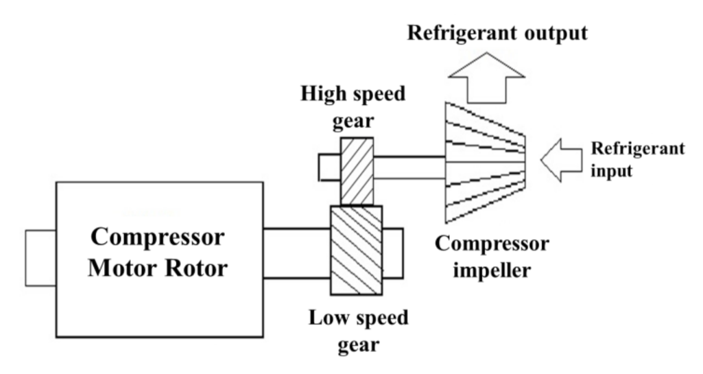
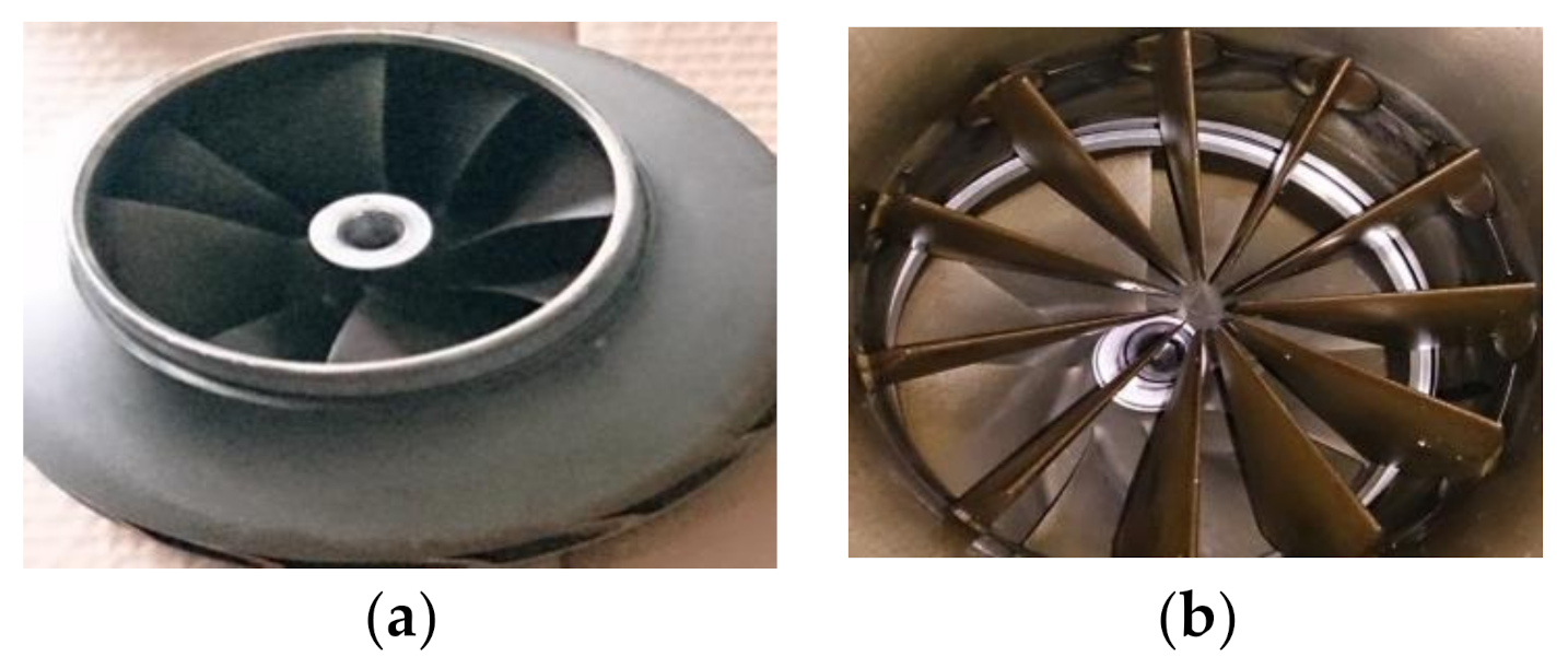
The general refrigerant R-134a centrifugal compressor can use the low-speed gear to drive the high-speed gear, as shown in Figure 1, to make the impeller operate at high speed. As shown in Figure 2a, the low-pressure and low-temperature gaseous refrigerant in the evaporator is inhaled, and the high-temperature and high-pressure gaseous refrigerant is discharged to the condenser through the high-speed rotating centrifugal force to exchange heat with the cooling water, so that the refrigerant becomes a high-pressure and normal temperature liquid refrigerant. Then, the expansion valve of the refrigerant controller is used for depressurizing and throttling to form a low-pressure and low-temperature liquid refrigerant, which enters the evaporator for heat exchange with ice water, so that the refrigerant becomes a low-pressure and low-temperature gaseous refrigerant and returns to the compressor, forming a refrigeration cycle.
The constant-frequency centrifuge controls the loading and unloading capacity through the inlet guide vanes (IGV) at the suction end of the compressor, as shown in Figure 2b. The IGV opening is changed through the temperature difference between the ice water set temperature and the actual ice water outlet temperature. The larger the temperature difference, the larger the opening, the smaller the temperature difference, and the smaller the opening, which is proportional to the relationship. However, the speed of the compressor motor does not change, maintaining the original speed. In the loading and unloading control mode, in addition to the original IGV control, the compressor motor is equipped with a frequency converter to change the voltage and frequency to control the compressor motor speed, reducing the operating current and power consumption and achieving the benefit of saving energy. The principle of energy saving can be proven by fan law, as follows:
The volume flow rate (Q) of the fan is directly proportional to the speed (N):
Static pressure (SP) is directly proportional to the square of fan speed (N):
The horsepower (kW) is proportional to the third power of the fan speed (N):
3. Maglev Centrifugal Compressor Water Chiller
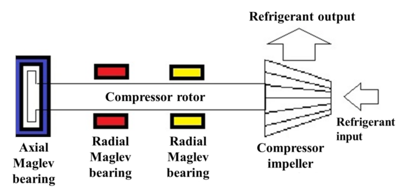
The active magnetic bearing (AMB) is used to replace the traditional bearing in the frequency conversion centrifugal compressor. The AMB can suspend the motor axis in the center of the bearing, forming a friction-free operation. The compressor shaft consists of two groups of radial magnetic bearings and one group of axial magnetic bearings to balance the radial force and axial force generated by the high-speed operation of the compressor shaft, as shown in Figure 3. Because the axis is suspended, the starting current is quite low. Only a small amount of work is needed to start the maglev compressor. At the same time, the low-speed and high-speed gear assembly of the traditional centrifugal compressor is reduced, which greatly reduces the volume and weight of the compressor. The Maglev compressor without high-speed and low-speed gears in the compressor does not need to lubricate the bearings and gears. In the design, all the refrigeration oil circuit systems of the traditional centrifugal compressor are removed, including the oil barrel, oil pump, oil separator, oil filter screen, oil heater, oil pipeline and all the parts and equipment of other refrigeration oil circuit systems, which reduces the volume of the ice water main engine. The operation efficiency is improved, the cost of regular maintenance and replacement of refrigeration oil, oil filter, and oil analysis is saved, and the impact of pollution and waste oil treatment on the environment is also reduced [7].
4. Coefficient of Performance (COPR)
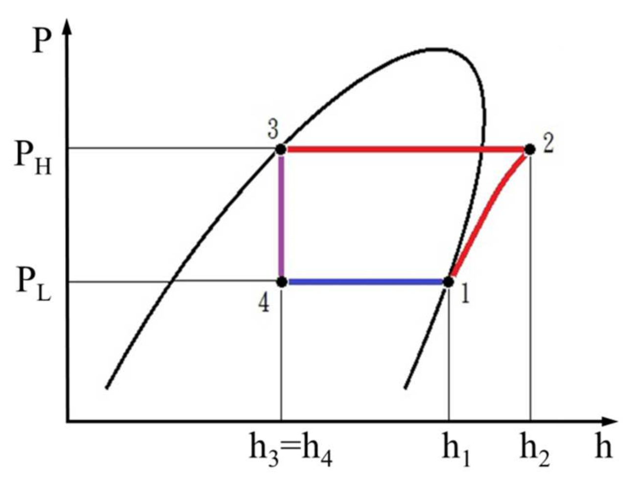
The Mollier Chart of the theoretical ideal refrigeration cycle is shown in Figure 4.
1 → 2: Isentropic compression of the compressor;
2 → 3: Isobaric condensation of the condenser;
3 → 4: Isoenthalpy expansion of the expansion valve; and
4 → 1: Isobaric evaporation of the evaporator.
P: Absolute pressure value (Pabs.) (MPa)
h: Enthalpy value (kJ/kg)
(1). Theoretical compression work (kJ/kg): W = h2 − h1,
(2). Theoretical condensation heat discharge (kJ/kg): qc = h2 − h3,
(3). Theoretical evaporation heat absorption (kJ/kg): qe = h1 − h4, and
(4). Theoretical formula: COPR = =.
5. Energy Efficiency Ratio (EER)
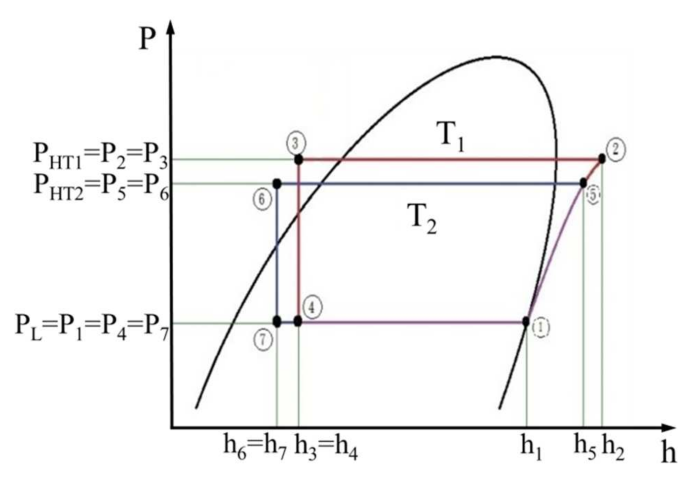
The design condensing pressure of the chiller is point P5; the operation sequence point of the refrigeration cycle is 1→5→6→7→1, as shown in Figure 5; the compressor work is equal to h5 − h1; and the refrigeration capacity of the evaporator is equal to h1 − h7. The COPR of point P5 is shown below.
COPR = refrigeration capacity of the evaporator/compression work of the compressor
When the inlet water temperature of the cooling water is high T1, resulting in a poor cooling efficiency of the chiller, point P5 will rise to point P2; the refrigeration cycle operational sequence point is 1→2→3→4→1, as shown in Figure 5; the compressor work is equal to h2 − h1; and the refrigeration capacity of evaporator is equal to h1 − h4. The COPR of point P2 is as follows.
COPR = refrigeration capacity of the evaporator/compression work of the compressor
The compression work of the compressor of point P2 is greater than that of point P5, and the refrigeration capacity of the evaporator of point P5 is greater than that of point P2. According to the above description, the COPR of point P5 is higher than that of point P2, and the inlet water temperature of the cooling water has a direct effect on the COPR of chiller efficiency. When the water inlet temperature of the cooling water is low and the power consumption of the compressor is relatively reduced, maintaining a good heat dissipation rate in the cooling tower can help the chiller achieve an energy-saving efficiency.
P: Absolute pressure value (Pabs) (MPa): P2 = P3 > P5 = P6 > P1 = P4 = P7.
h: Enthalpy (kJ/kg): h2 > h5 > h1 > h3 = h4 > h6 = h7.
T: Temperature (°C): T1 > T2.
In the basic refrigeration cycle, the compressor does the work (compression heat), the condenser releases heat, the expansion valve controls the refrigerant mass flow rate, and the evaporator absorbs heat.
This cycle is a refrigeration cycle, and COPR is the ratio of the net refrigeration capacity of the evaporator to the compression work of the compressor, i.e., a ratio of the net refrigerating capacity to the total input power at any given set of rating conditions. COPR is the refrigeration capacity of the evaporator (kW)/compression input work of the compressor (kW). The cooling COPR is calculated as follows [27,28]:
EER is the cooling capacity of the evaporator divided by the power consumption of the compressor, i.e., the ratio of the net refrigerating capacity to the total input power at any given set of rating conditions. EER is the cooling capacity of the evaporator (Qevap.) (kcal/hr)/power consumption of the compressor (Winput) (W). The EER is calculated as follows [27,28]:
The power input per capacity (kW/tonR) is the ratio of the total input power to the net refrigerating capacity at any given set of rating conditions. The power input per capacity is calculated as follows [27,28]:
where the thermal equivalent capacity (kW) is 860 kcal/hr; 1 kcal is 3.968 BTU; the unit conversion is 1 US RT = 12,000 BTU/hr = (12,000 BTU/hr)/(3.968 BTU) = 3024 kcal/hr = (3024 kcal/hr)/(860 kcal/hr) = 3.516 kW; COPR = EER/3.412 = 0.293 EER; the power input consumption per refrigeration capacity tonR (kW/tonR) = 3.516/COPR and kW/tonR = 12/EER.
6. IPLV.IP and NPLV.IP
Generally, the operating load percentage of the water chiller will change with the change in load demand because of climate factors, such as seasonal changes in spring, summer, autumn, and winter and different day and night conditions, among other reasons. This paper focuses on the integrated part-load value (IPLV.IP) and non-standard part-load value (NPLV.IP) of the water-cooled chiller. IPLV.IP is a single number part-load efficiency figure of merit calculated using the method described in this standard at standard rating conditions. NPLV.IP is a single number part-load efficiency figure of merit calculated using the method described in this standard, referring to conditions other than IPLV.IP conditions, i.e., for units with water-cooled condensers that are not designed to operate at standard rating conditions, but is not used for air-cooled and evaporatively-cooled chillers. The AHRI standard records relevant standards and calculation equations [27,28]. The purpose of the AHRI standard is to establish the following for water-chilling and heat pump water-heating packages using the vapor compression cycle: definitions, test requirements, rating requirements, minimum data requirements for published ratings, marking and nameplate data, conversions and calculations, nomenclature, and conformance conditions. This standard is intended for the guidance of the industry, including manufacturers, engineers, installers, efficiency regulators, contractors, and users. Therefore, we have focused on real-field operation differences in the refrigeration capacity tonR of water-cooled chillers, which must be understood when designing water-chilling chiller packages and evaluating the performance of water chillers equipped with constant- or variable-frequency centrifugal compressors.
The part-load energy efficiencies at proportions of 100%, 75%, 50%, and 25% load to the operation weight factor are 0.01, 0.42, 0.45, and 0.12, respectively. When COPR and EER are used to calculate IPLV.IP or NPLV.IP = 0.01A + 0.42B + 0.45C + 0.12D, where A = COPR or EER at 100% load, B = COPR or EER at 75% load, C = COPR or EER at 50% load, and D = COPR or EER at 25% load [27,28].
A = Power input per capacity, kW/tonR at 100% load,
B = Power input per capacity, kW/tonR at 75% load,
C = Power input per capacity, kW/tonR at 50% load, and
D = Power input per capacity, kW/tonR at 25% load.
The operating conditions and calculation and the design conditions and equations of the water chiller are also explained and determined by AHRI. The outlet temperature of the ice water is 44 °F (6.67 °C), the inlet temperature is 54 °F (12.22 °C), and the temperature difference is Δ = 10 °F (5.55 °C). The flow rate of the ice water is 2.4 GPM/tonR (9.08 LPM/tonR) The inlet temperature of the cooling water is 85 °F (29.44 °C), the outlet temperature is 94.5 °F (34.72 °C), and the temperature difference is Δ = 9.5 °F (5.28 °C). The flow rate of the cooling water is 3 GPM/tonR (11.36 LPM/tonR). The fouling coefficients of the evaporator and condenser are 0.0001 and 0.00025, respectively.
The heat exchange capacity of the evaporator and condenser can be calculated by the following formula:
: Heat exchange heat (BTU/hr or kW),
: Fluid mass flow rate (lb/hr or kg/hr),
Cp: Specific heat of the fluid (BTU/lb_℉ or kJ/kg_K),
ΔT: Temperature difference (Tinput–Toutput) of the fluid (℉ or ℃)
Q = U × A × LMTDevap.
U: Total heat transfer coefficient (BTU/hr_ft2_℉ or kcal/hr_m2_℃),
A: Heat exchange area (ft2 or m2),
LMTDevap.: Logarithmic average temperature of the fluid and refrigerant in the heat exchanger or logarithmic effective average temperature.
LMTDevap.: logarithmic effective average temperature of the evaporator (°F or °C),
Te: refrigerant saturation temperature of the evaporator (°F or °C),
Ti: inlet fluid temperature of the evaporator (°F or °C), and
To: outlet fluid temperature of the evaporator (°F or °C).
7. Analysis Condition Setting
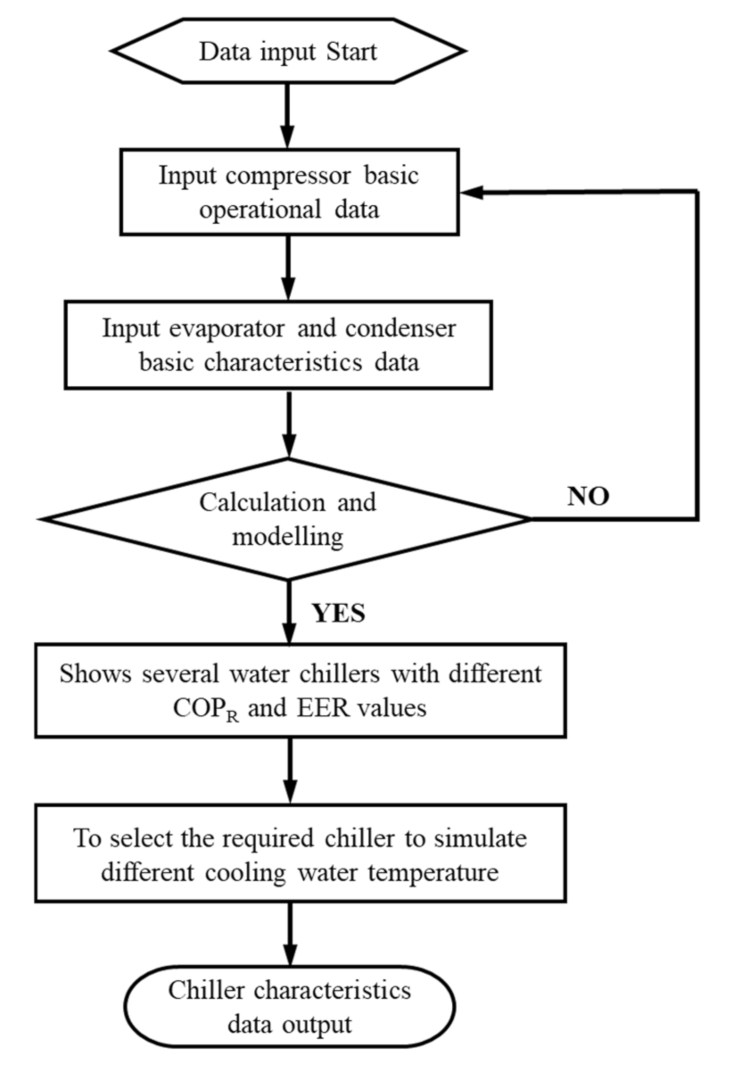
The operational mode and flow chart of the commercial consumer code (Design Software Tools MD2016 Version for HVAC Water Chiller System) program are as follows:
- (1)
- The required data of the compressor are input: the compressor type, manufacture, voltage, frequency, refrigerating capacity, start-up mode, and capacity control mode.
- (2)
- The required data of the evaporator and condenser are input: water inlet temperature, water outlet temperature, copper tube fouling coefficient, copper tube material, heat exchange medium, and heat exchange circuit number.
- (3)
- Commercial consumer code program simulation and calculation are selected for input and output data prediction and evaluating performance results, including compressor, evaporator, and condenser are required input data and Equations (3)–(8) calculation analysis according to the AHRI standard guide [27,28].
- (4)
- The analysis results show several chillers with different COPR and EER values.
- (5)
- The required chiller is selected to simulate the variable-cooling water temperature or constant cooling water temperature.
- (6)
- The water chiller type selection table is the output data of the commercial consumer code program.
8. Condition Setting
Based on conditions of 460 V/60 Hz, 12 °C ice water in the inlet evaporator, 7 °C ice water in the outlet evaporator to the inter room, 32 °C cooling water in the inlet condenser, and 37 °C cooling water in the outlet condenser of the cooling tower, the centrifugal chiller is input into the commercial consumer code model program selection and simulation to analyze the following: 200, 250, 300, 380, 500, and 700 RT of the fixed-cooling water temperature (Table 1), constant-frequency, variable-frequency, Maglev variable-frequency, characteristic data of the chiller, COPR, and EER variable-cooling water temperature (Table 1) of 200, 250, 300, 380, 500, and 700 RT, constant-frequency, variable-frequency, Maglev variable-frequency, characteristic data of the chiller, COPR, and EER analysis.
The constant- and variable-frequency water chillers at 200, 250, 300, 380, 500, and 700 RT use a single-compressor system. The Maglev variable-frequency water chiller uses a Maglev variable-frequency compressor because the relevant manufacturer equipment design conditions are limited. Therefore, 200, 250, 300, and 380 RT Maglev variable-frequency chillers are double-compressor systems, whereas 500 and 700 RT Maglev variable-frequency chillers are single-compressor systems. Table 2 shows the temperature output values of fixed- and variable-cooling water inlets at different operational percentages according to the commercial consumer code program calculation.
9. Parameter Setting
Through the commercial consumer code program and monitoring equipment of the Maglev variable-frequency chiller, the operation value of the chiller is recorded and compared with the operational selection table of the chiller. Whether the selection table value generated by the matching commercial consumer code program simulation is consistent with the actual operation value on site is determined. Using the commercial consumer code simulation analysis prediction program and flow chart of the operational analysis in Figure 6, meeting the AHRI standard and certification is necessary to select the required tonR of the water chiller data for analysis.
In the real-field performance measurement of the Maglev variable-frequency water chiller, the monitoring equipment is used to measure the ice water outlet temperature, ice water inlet temperature, cooling water outlet temperature, cooling water inlet temperature, refrigerant pipe temperature, compressor contraction temperature, compressor exhaust temperature, evaluator pressure, condenser pressure, and motor current parameters value, as shown in Table 3.
The basic operation specifications of the actual water chiller are described. The ice water chiller using refrigerant R-134a has a voltage of 460 V/60 Hz, a current of 536 A, an input power of 411 kW, a cooling capacity of 2461 kW, a COPR performance of 6.0, and the evaporator entering is 12 °C, evaporator leaving is 7 °C, condenser entering is 32 °C, condenser leaving is 36.7 °C, evaporator flow is 7056 L/min, and condenser flow is 8820 L/min, as shown in Table 4.
For the actual water chiller real-field operation monitoring measurement position values, the monitoring data capture record is based on the actual water chiller real-field operation in the range of 80%, 70%, 60%, and 50% and the actual operation record average current is 402 A, 368 A, 325 A, and 262 A; ice water inlet temperature is 10.5 °C, 10.5 °C, 9.9 °C, and 9.5 °C; ice water outlet temperature is 7.0 °C, 6.9 °C, 7.0 °C, and 7.1 °C; cooling water inlet temperature is 32.6 °C, 30.8 °C, 29.5 °C, and 28.6 °C; cooling water outlet temperature is 37.3 °C, 35.3 °C, 33.1 °C, and 32.2 °C, as shown in Table 5.
Using the commercial consumer code program to simulate the operation mode of the water chiller, under the conditions of 100%, 90%, 80%, 70%, 60%, 50%, 40%, 30%, 20%, and 10%, the output analysis parameter is between 536 A and 85 A for the running average current; the ice water inlet temperature is between 12 °C and 7.5 °C; the ice water outlet temperature is consistently 7.0 °C; the cooling water inlet temperature is between 32 °C and 25.4 °C; the cooling water outlet temperature is between 36.7 °C and 25.9 °C, as shown in Table 6.
The results show that the parameters of the actual water chiller are almost the same as those of the water chiller running mode simulated by the commercial consumer code program under 80%, 70%, 60%, and 50% conditions, which shows that it is beneficial to simulate the water chiller running mode using the commercial consumer code program. In addition, the working conditions of the actual water chiller in real-field operation can be checked, and the commercial consumer code program can be established to simulate the prediction of the water chiller operation mode, query the specification table of machine selection performance, and select a performance map that conforms with AHRI standard [27,28] regulation, serving as a reference for future design, change, planning, and construction. It can easily and quickly understand the impact of load, analyze the most favorable matching parameters of the water chiller, and the commercial consumer code program can be used to simulate the operation mode of the water chiller, in order to accurately design and select the reference database for matching the different tonR of constant-frequency or variable-frequency water chiller operation, as shown in Table 7.
10. Results and Discussion
The results of this study are combined with practical design, theoretical calculation, and analysis according to the AHRI standard guide formula [27,28], on-site selection of the design parameters of the water chiller, setting the environmental air conditioning load capacity, according to the operation analysis process (Figure 6). The parameters are input into the commercial consumer code program analysis, the output results are analyzed, and the operation performance matching of the water chiller engine in different tonnage ranges is discussed. In order to select a water chiller that has the performance requirements of a high energy-saving rate and low power consumption per tonnage. The performance curves of 200, 250, 300, 380, 500, and 700 RT are analyzed and selected when the water chiller runs with different compressors in different tonnage ranges below 1000 RT. This calculation mode is used as a reference for the selection of the water chiller ice water tonnage, high COPR capacity, high EER capacity, and alternate operating load for designing future indoor air-conditioning load. According to the influence of IPLV.IP and NPLV.IP, water chillers will have different performance levels due to different compressor types. Therefore, the performance of the water chiller is very important for energy-saving, and the change in inlet water temperature will also affect the performance of the water chiller. Therefore, sets of performance curve charts for water chiller performance operation and a process for selecting water chiller parameter calculation data must be established to facilitate air conditioning load design and rotational operation. The results can be used to quickly query the baseline application of the best energy-efficient operation of different water chiller tonnage ranges and avoid overdesign performance or insufficient design performance.
10.1. Fixed-Cooling Water Inlet Temperature
10.1.1. Fixed-Cooling Water Inlet Temperature of the 200–700 RT Constant-Frequency Centrifugal Water Chiller
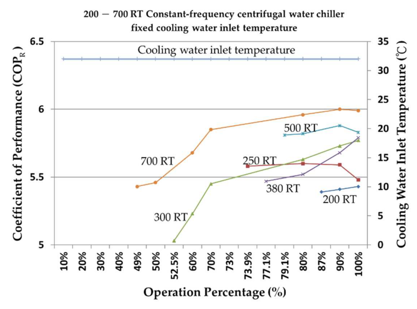
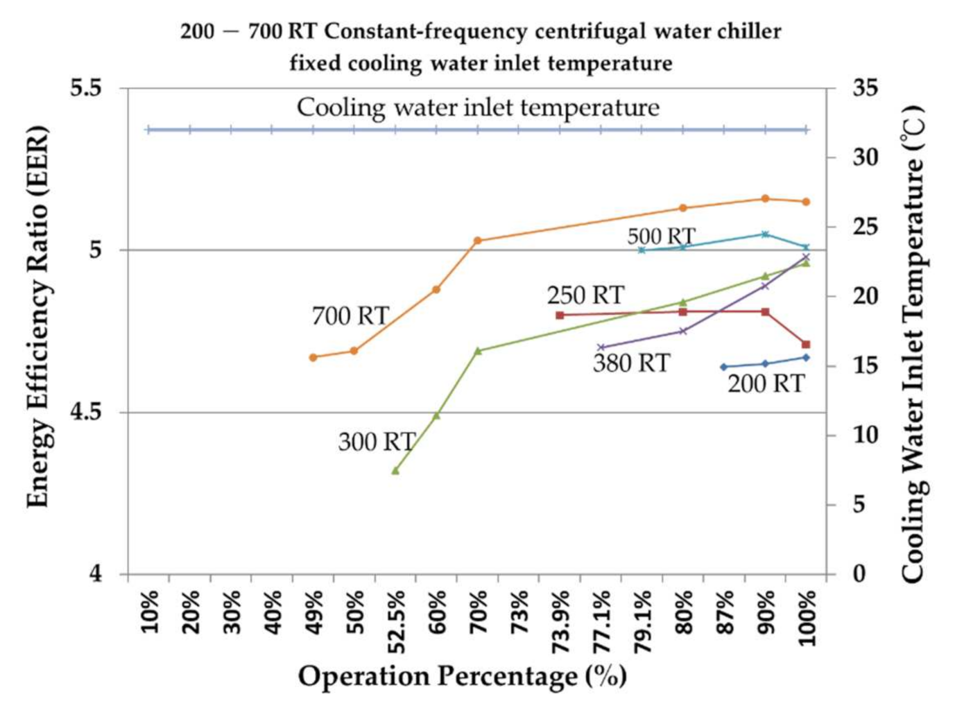
Figure 7 and Figure 8 show that when the water inlet temperature of the cooling water is fixed at 32 °C, the speed of the constant-frequency water chiller is fixed, the condensing pressure is fixed and high, and the load percentage of the water chiller is relatively limited because the surge phenomenon of the centrifugal compressor must be avoided; thus, it cannot operate at a low load, which is suitable for a place where full-load operation is required.
Figure 7 shows that the COPR can be maintained between 5.0 and 6.0 when the operational load percentage mode is above 60%. Figure 8 shows that the EER can be maintained between 4.5 and 5.2 when the operational load percentage mode is above 60%. The performance trends of the COPR and EER are in agreement because the EER is 3.412 COPR.
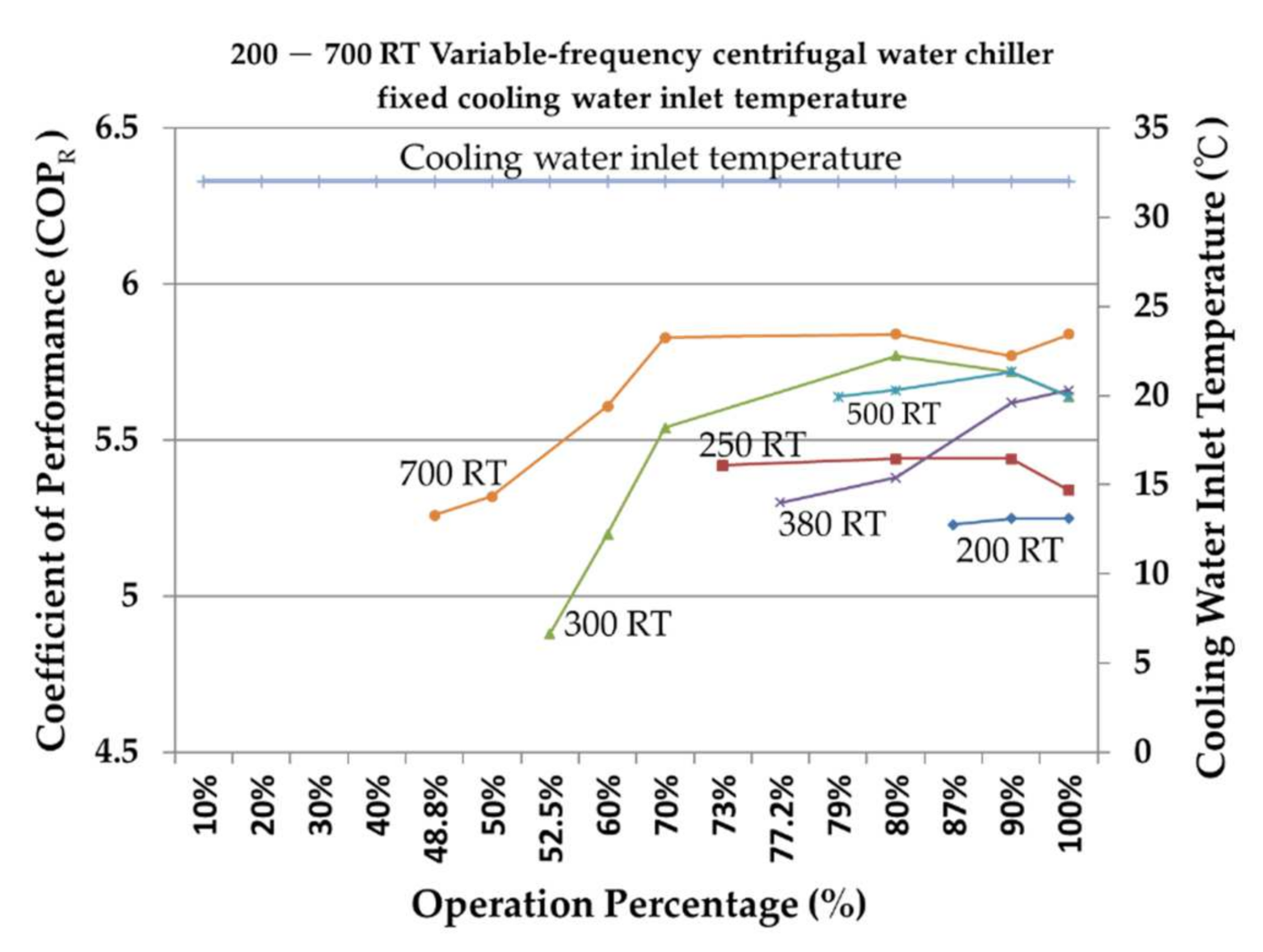
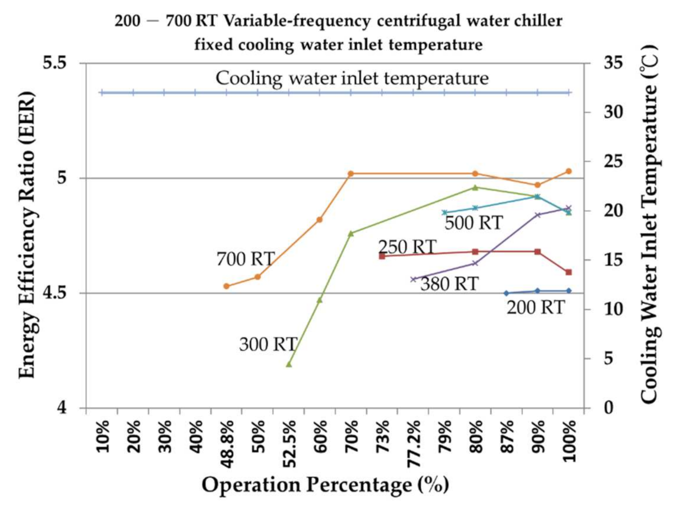
10.1.2. Fixed-Cooling Water Inlet Temperature of the 200–700 Rt Variable-Frequency Centrifugal Water Chiller
Figure 9 and Figure 10 show that when the water inlet temperature of the cooling water is fixed at 32 °C, although the inverter host can reduce the speed by changing the voltage frequency to achieve an energy-saving effect, the load percentage of the inverter host is also limited because the water inlet temperature of the cooling water is fixed, and the condensation pressure is fixed and high to prevent the occurrence of surge. At the same time, the value is displayed in the high negative range because the frequency converter is equipped with a frequency converter, which consumes slightly more energy than the fixed-frequency host, and the COPR and EER are not as ideal as in the fixed-frequency host. Special attention should be paid to the selection of the matching.
Figure 9 shows that the COPR P of the 300, 500, and 700 RT can be maintained between 5.2 and 5.8 when the operational load percentage mode is above 60%. The averages COPR of 200, 250, and 380 RT are relatively lower than 5.4. Figure 10 shows that the EER of the 200, 250, 300, 380, 500, and 700 RT can be maintained between 4.5 and 5.0 when the operational load percentage mode is above 60%. The performance trends of the COPR and EER are similar.
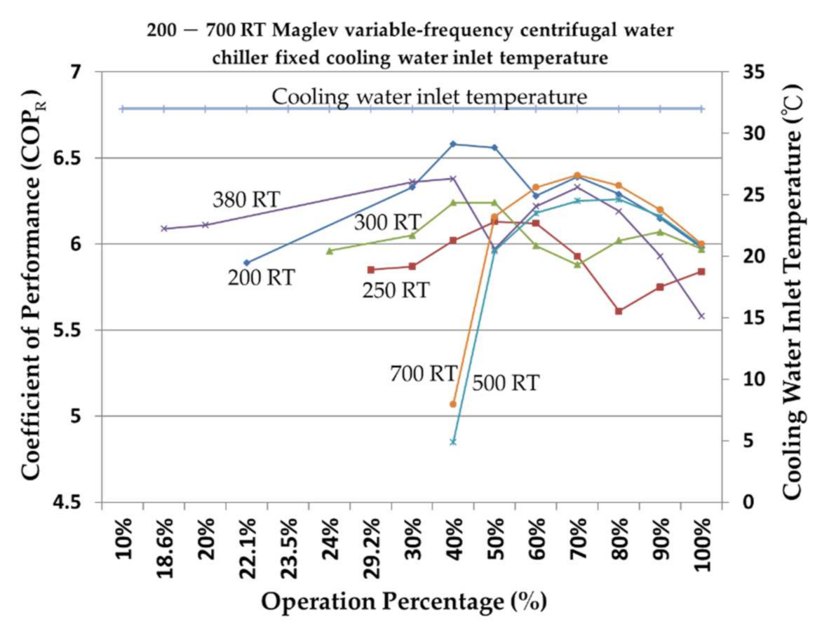
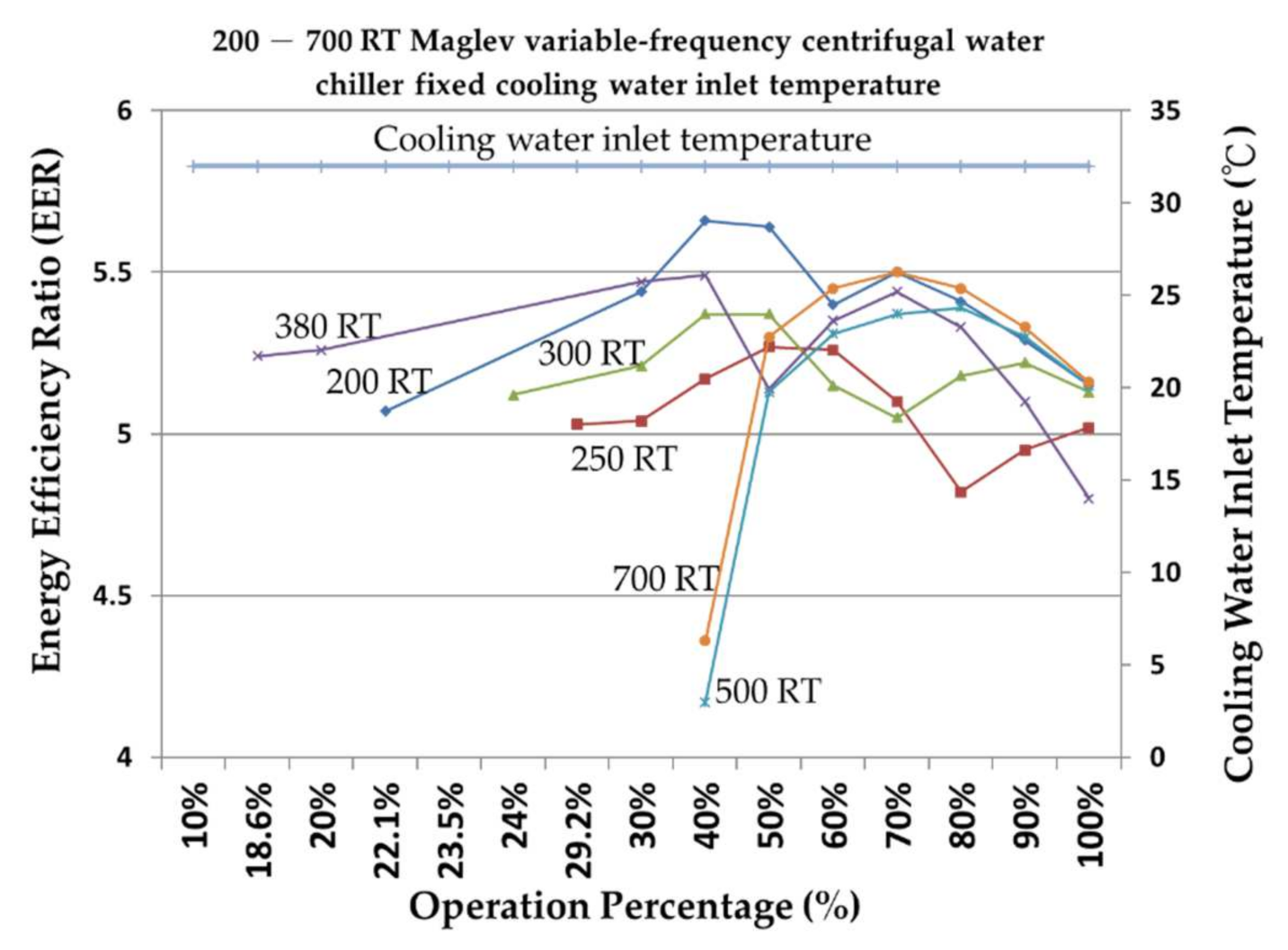
10.1.3. Water Inlet Temperature of the Fixed-Cooling Water for the 200–700 Rt Maglev Variable-Frequency Centrifugal Water Chiller
Figure 11 and Figure 12 show that, when the water inlet temperature of the cooling water is fixed at 32 °C, the high-pressure gaseous refrigerant head at the discharge end of the compressor can be increased by increasing the speed of the Maglev variable-frequency centrifugal compressor to avoid the surge phenomenon of the compressor. The operating load percentage of the 200–700 RT Maglev variable-frequency centrifugal water chiller can reach 40% compared to the fixed- and variable-frequency host, the low-load operation conditions of the system have more changes in the operation capacity for places where the thermal load demand and load change greatly.
Figure 11 shows that the average COPR of the 200, 250, 300, 380, 500, and 700 RT is between 5.6 and 6.5 when the operational load percentage mode is above 40%. Figure 12 shows that the average EER of the 200, 250, 300, 380, 500, and 700 RT is between 4.6 and 5.5 when the operational load percentage mode is above 40%. The performance trend of the COPR and EER are similar.
10.2. Variable-Cooling Water Inlet Temperature
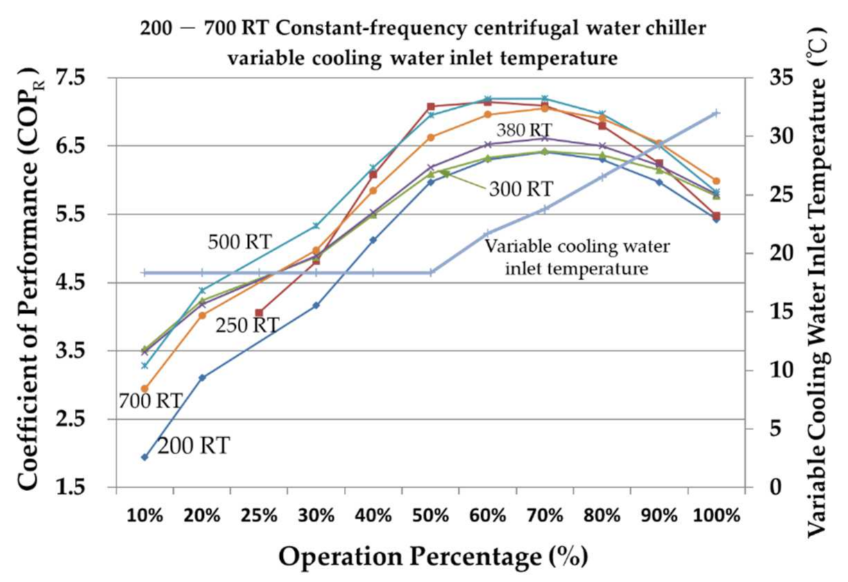
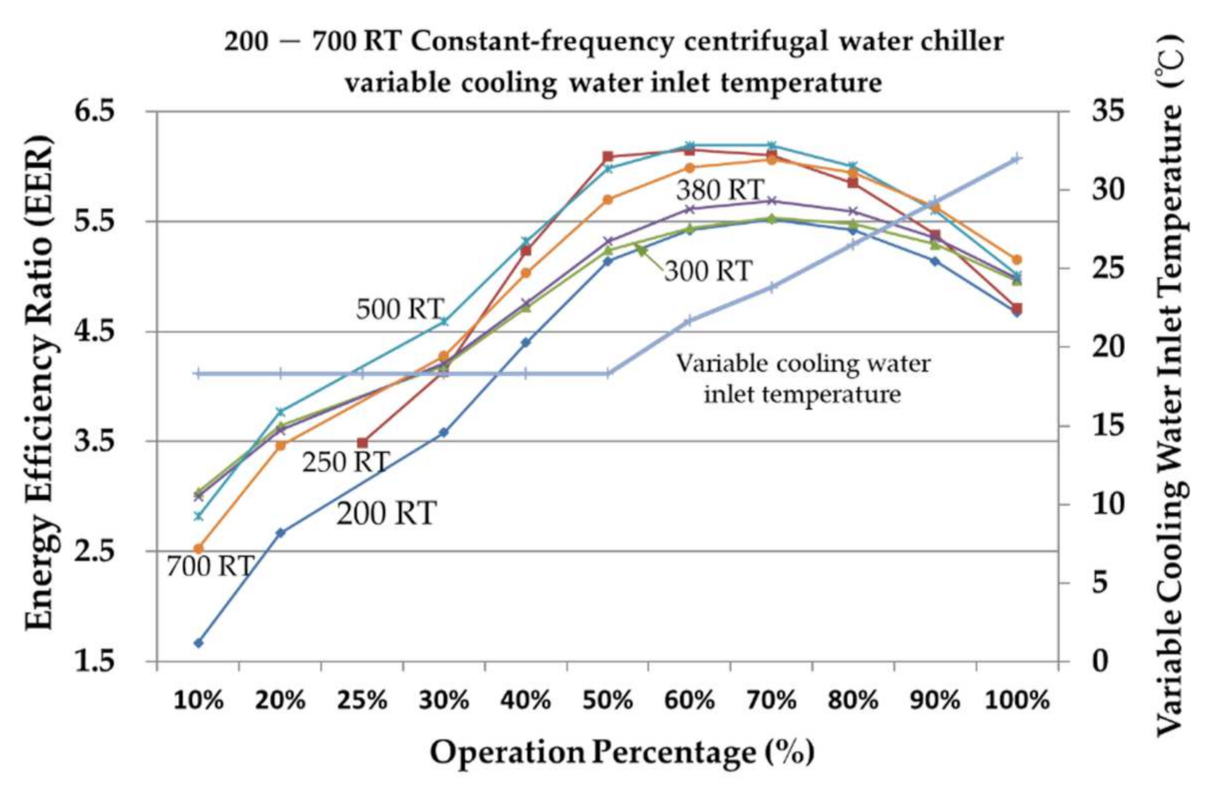
10.2.1. Inlet Temperature Value of the Variable-Cooling Water for the 200–700 Rt Constant-Frequency Centrifugal Water Chiller
Figure 13 and Figure 14 show that when the water inlet temperature of the cooling water drops from 32 °C to 18.33 °C, the condensation pressure also drops, and the constant-frequency water chiller of each tonnage can run to 30% of the low load. The COPR and EER of the 250 RT fixed-frequency water chiller are lower than 60% of the operating load and the COPR and EER of other fixed-frequency water chillers of each tonnage are lower than 70% of the operating load. The COPR of each tonnage is higher between 6.3 and 7.2 and the EER of each tonnage is higher between 5.4 and 6.2 when the operational load percentage mode is between 60% and 70%.
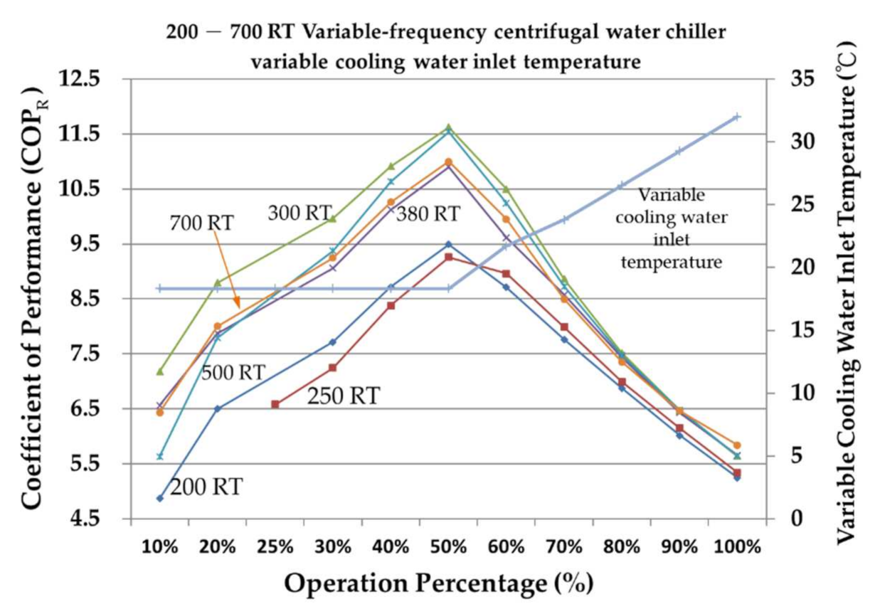
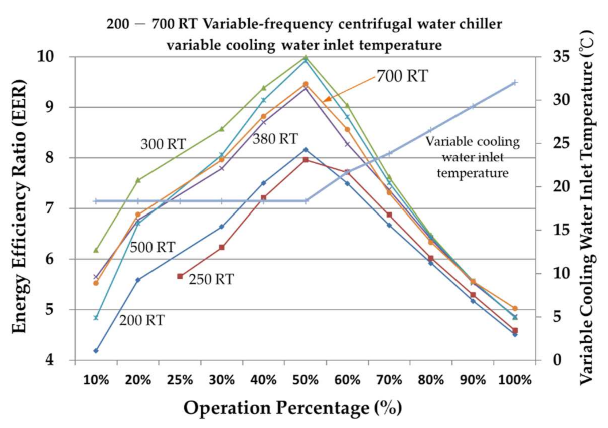
10.2.2. Inlet Temperature Value of Variable-Cooling Water for the 200–700 Rt Variable-Frequency Centrifugal Water Chiller
Figure 15 and Figure 16 show that when the water inlet temperature of the cooling water drops from 32 °C to 18.33 °C, the condensation pressure drops, and the constant-frequency water chiller of each tonnage can run to 30% of the low load. The COPR and EER of each tonnage of the variable-frequency water chiller are lower than 50% of the operating load and then begin to decrease. With the decrease of the cooling water inlet temperature, the COPR and EER of the variable-frequency water chiller are better than those of the constant-frequency water chiller; the lower the operating load, the more evident it is.
The maximum COPR of each tonnage is between 9.26 and 11.62, and the maximum EER of each tonnage is between 7.96 and 9.99 when the operational load percentage mode is 50%. The COPR of each tonnage is gradually increased between 4.87 and 11.62 and the EER of each tonnage is gradually increased between 4.19 and 9.99 when the operational load percentage mode is between 10% and 50%. The COPR of each tonnage is gradually decreased between 11.62 and 5.25 and the EER of each tonnage is gradually decreased between 9.99 and 4.51 when the operational load percentage mode is between 50% and 100%.
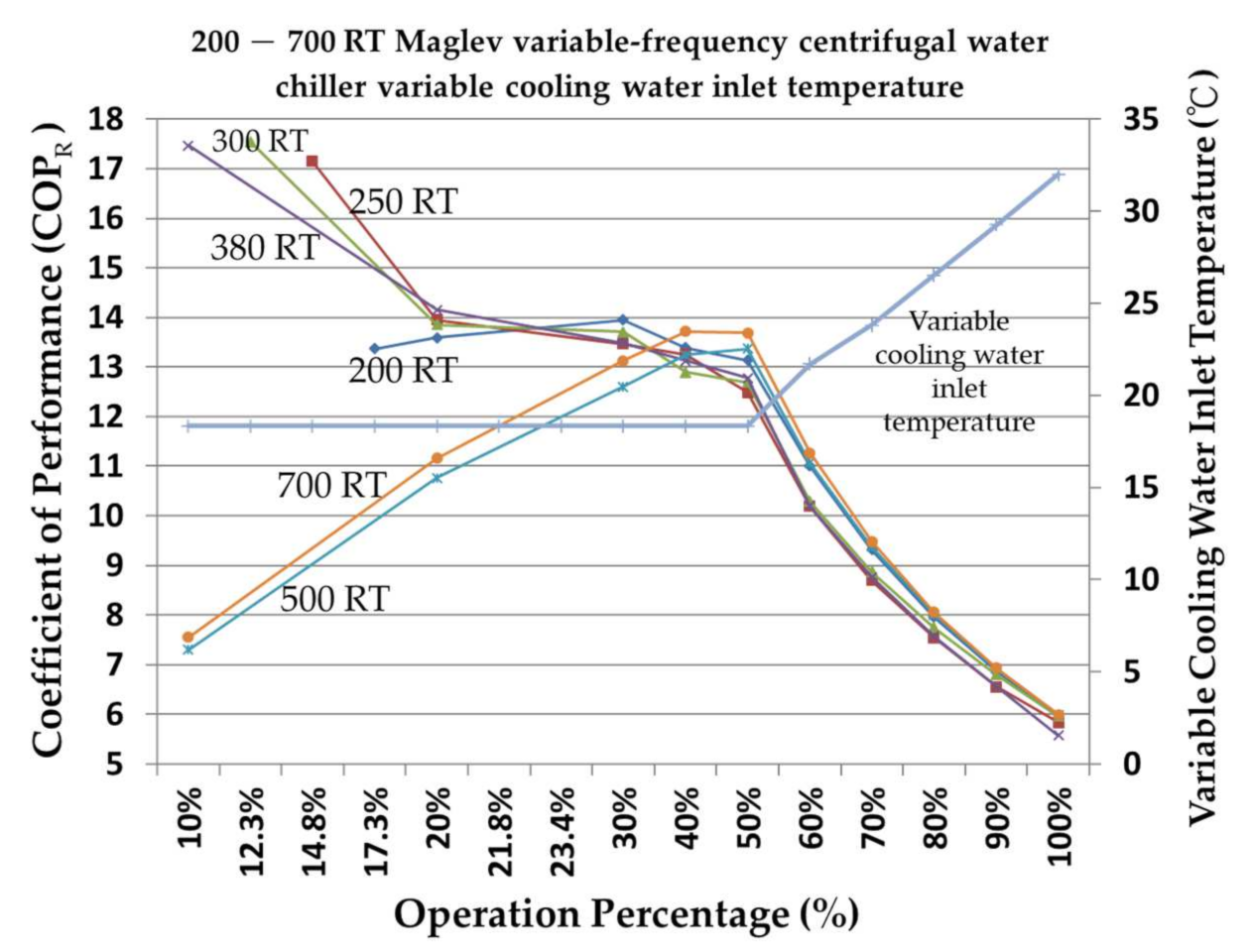
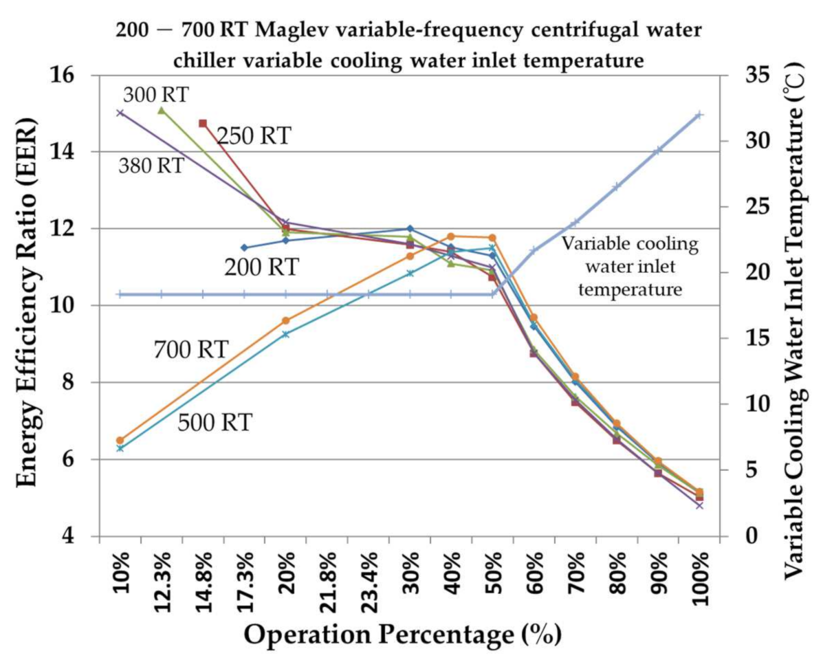
10.2.3. Inlet Temperature Value of Variable-Cooling Water for the 200–700 Rt Maglev Variable-Frequency Centrifugal Water Chiller
Figure 17 and Figure 18 show that when the water inlet temperature of the cooling water drops from 32 °C to 18.33 °C, the condensation pressure drops, and the constant-frequency water chiller of each tonnage can run to 20% of the low load. The results show that the COPR of 200–380 RT is more than 12 when the load is less than 50%, the highest COPR of 300 RT is 17.55 when the load is 12.3%, the COPR of 500 RT is 13.37 when the load is 50%, and the COPR of 700 RT is 13.72 when the load is 40%.
The COPR of 200, 250, 300, and 380 RT is between 17.47 and 12.49 when the operational load percentage mode is between 10% and 50%. The COPR of 500 RT and 700 RT is gradually decreased between 13.37 and 5.99 when the operational load percentage mode is between 50% and 100%. The EER of 200, 250, 300, and 380 RT is between 15.09 and 10.74 when the operational load percentage mode is between 10% and 50%. The EER of 500 RT and 700 RT is gradually decreased between 11.50 and 5.15 when the operational load percentage mode is between 50% and 100%.
10.3. Design Case Study Analysis and Simulation Option
10.3.1. Design Case Study Analysis 1
Suppose that a traditional industry company has a load demand of 2000 RT, the basic load is about 1500 RT, and the variable load is about 500 RT. How is the option mode of the chiller determined? The fixed inlet temperature of 32 °C cooling water is selected as the chiller because the cooling water tower is shared by the whole site, and the inlet temperature of the chiller is not easy to control. For the basic load, the constant-frequency chiller is selected, which runs at full load for a long time, and the Maglev variable-frequency chiller is selected for the variable load due to its excellent part-load performance to meet the demand when the load changes, as shown in Table 8.
- A.
- Option mode 1: total is 2000 RT
- (1)
- 500 RT constant-frequency chillers are two sets (full-load efficiency COPR is 5.83).
- (2)
- 500 RT variable-frequency chillers are two sets (full-load efficiency COPR is 5.64).
- (3)
- Average full-load COPR is 5.735, and power input consumption (kW) per capacity tonR (RT) is 0.613.
- B.
- Option mode 2: total is 2000 RT
- (1)
- 500 RT constant-frequency chillers are three sets (full-load efficiency COPR is 5.83).
- (2)
- 500 RT Maglev variable-frequency chiller is one set (full-load efficiency COPR is 5.99).
- (3)
- Average full-load COPR is 5.87, and power input consumption (kW) per capacity tonR (RT) is 0.599.
- C.
- Option mode 3: total is 2100 RT
- (1)
- 700 RT constant-frequency chillers are two sets (full-load efficiency COPR is 5.99).
- (2)
- 700 RT Maglev variable-frequency chiller is one set (full-load efficiency COPR is 6.0).
- (3)
- Average full-load COPR is 5.993, and power input consumption (kW) per capacity tonR (RT) is 0.587.
10.3.2. Design Case Study Analysis 2
Suppose a high-technology industrial company has a load demand of 1200 RT, the basic load is about 600 RT, and the variable load is about 600 RT. How is the option mode of the water chiller unit determined? The water inlet temperature of variable-cooling water can be selected as the chiller because the cooling water tower is a special cooling water tower for the chiller. The fixed-frequency chiller is mainly used for the basic load and supplemented by the variable-frequency chiller. For the variable load, the Maglev variable-frequency chiller is selected due to its excellent part-load performance to meet the demand when the load changes. Option modes 3 and 4 exceed the total demand of frozen tons, but the cooling water is the variable part-load efficiency of the variable-frequency chiller, and the Maglev variable-frequency chiller of the water inlet temperature is higher than that of the full load. They are also included in the reference option mode, as shown in Table 10.
- A.
- Option mode 1: total is 1200 RT
- (1)
- 300 RT constant-frequency chillers are two sets (full-load efficiency COPR is 5.77).
- (2)
- 300 RT Maglev variable-frequency chillers are two sets (full-load efficiency COPR is 5.97).
- (3)
- Average full-load COPR is 5.87, and power input consumption (kW) per capacity tonR (RT) is 0.599.
- B.
- Option mode 2: total is 1300 RT
- (1)
- 300 RT constant-frequency chillers are two sets (full-load efficiency COPR is 5.77).
- (2)
- 700 RT Maglev variable-frequency chiller is one set (full-load efficiency COPR is 6.0).
- (3)
- Average full-load COPR is 5.847, and power input consumption (kW) per capacity tonR (RT) is 0.601.
- C.
- Option mode 3: total is 1300 RT
- (1)
- 300 RT variable-frequency chillers are two sets (full-load efficiency COPR is 5.64).
- (2)
- 700 RT Maglev variable-frequency chiller is one set (full-load efficiency COPR is 6.0).
- (3)
- Average full-load COPR is 5.82, and power input consumption (kW) per capacity tonR (RT) is 0.61.
- D.
- Option mode 4: total is 1400 RT
- (1)
- 700 RT constant-frequency chiller is one set (full-load efficiency COPR is 5.99).
- (2)
- 700 RT Maglev variable-frequency chiller is one set (full-load efficiency COPR is 6.0).
- (3)
- Average full-load COPR is 5.995, and power input consumption (kW) per capacity tonR (RT) is 0.604.
The results of the design case study analysis 2, shown in Table 11, combining the flow chart of the operational analysis from Figure 6 and COPR and kW/RT results, shows that option mode 1 has the best energy-saving potential of the four options.
The above case study examples show that the selection and collocation of water chiller unit have the following precautions:
- (1)
- Water Inlet temperature of the cooling water: affects the efficiency of water chiller unit.
- (2)
- Distribution weight of the basic load and variable load: compressor type selection.
- (3)
- Multiset chiller option mode: to avoid single-set damage, no chiller can be used.
- (4)
- The water chiller can match modes and alternatives using:
- (a)
- If there are no financial constraints, users can preferentially choose the use of the high-efficiency Maglev variable-frequency centrifugal water chiller.
- (b)
- If there are financial constraints, users can choose the use of a constant-frequency centrifugal water chiller or a variable-frequency centrifugal water chiller.
- (c)
- If the budget can be allocated, users can choose to use a high-efficiency Maglev variable-frequency centrifugal water chiller with a constant-frequency centrifugal water chiller, or a high-efficiency Maglev variable-frequency centrifugal water chiller with a variable-frequency centrifugal water chiller, or a constant-frequency centrifugal water chiller with a variable-frequency centrifugal water chiller.
- (5)
- On the limitation of budget amount.
11. Conclusions
When the water inlet temperature of the cooling water is fixed and the full load is 100%, the COPR and EER of the Maglev variable-frequency centrifugal chiller are better than those of the constant-frequency centrifugal water chiller, and that of the constant-frequency centrifugal water chiller is better than that of the variable-frequency centrifugal water chiller. The larger the freezing tonnage of the variable-frequency centrifugal water chiller, the smaller the difference between COPR and EER. In addition to the low-load operation of the Maglev variable-frequency centrifugal water chiller, the constant- and variable-frequency centrifugal water chillers are operational above 87% load at 200 RT, above 73% load at 250 RT, above 52.5% load at 300 RT, above 77.1% load at 380 RT, above 79% load at 500 RT, and above 48.8% load at 700 RT.
When the inlet cooling water temperature is changed and the full load is 100%, the COPR and EER of the Maglev variable-frequency centrifugal water chiller are better than those of the constant-frequency water chiller, and that of constant-frequency centrifugal water chiller is better than that of variable-frequency centrifugal water chiller. The COPR and EER of the water chiller with time-varying cooling water inlet temperature is better than that with fixed-cooling water inlet temperature under partial-load operation, especially under 70% load operation. The COPR of the Maglev variable-frequency centrifugal chiller can exceed 10, which is quite efficient. The results of the analysis show that the COPR and EER values of various centrifugal water chillers are different during operation. The COPR and EER values of fixed- and variable-cooling water inlet temperatures are very different, especially in partial-load operation, but no substantial difference is observed in full-load operation mode.
Therefore, when designing the engineering demand of refrigeration and air conditioning and calculating the heat load, confirming the weight of the basic load as a percentage of the total load as well as the time and amount of change of the variable load is relatively important for matching the performance characteristics of the chiller, setting the operation mode properly, and avoiding overdesign or insufficient capacity in the design. It can achieve the ultimate goal of keeping the chiller running efficiently and saving the cost of power consumption.
Author Contributions
Conceptualization, C.-N.H.; methodology, C.-N.H. and S.-H.W.; validation, C.-N.H. and S.-H.W.; formal analysis, C.-N.H. and S.-H.W.; investigation, C.-N.H. and S.-H.W.; resources, C.-N.H. and S.-H.W.; data curation, C.-N.H. and S.-H.W.; writing—original draft preparation, C.-N.H.; writing—review and editing, C.-N.H.; visualization, C.-N.H. and S.-H.W.; supervision, C.-N.H.; project administration, C.-N.H. All authors have read and agreed to the published version of the manuscript.
Funding
This research received external funding from the Ministry of Science and Technology of Taiwan, the Republic of China, financially supporting this study under contract numbers MOST 107-2622-E-167-015-CC3.
Institutional Review Board Statement
Not applicable.
Informed Consent Statement
Not applicable.
Data Availability Statement
The data are not publicly available.
Acknowledgments
We would like to thank the Ministry of Science and Technology of Taiwan of the Republic of China for financially supporting this research under contract numbers MOST 107-2622-E-167-015-CC3. We would also like to thank C.-H. Su (S.-I.-H. Corp. Ltd., Taichung, Taiwan) for the experimental equipment testing energy-saving. I would like to thank my M.S. students S.-H. Lu, K.-H. Chen, C.-H. Cheng, S.-M. Chang, K.-W. Lee, and Y.-F. Hung for their support in completing the research plan for this paper.
Conflicts of Interest
The authors declare no conflict of interest.
References
- Energy Efficiency Standard of Water Chiller Unit in Air Conditioning System of Bureau of Energy, Ministry of Economic Affairs. Available online: https://www.moeaboe.gov.tw/ecw/populace/Law/Content.aspx?menu_id=1037 (accessed on 22 September 2020).
- Bureau of Energy, Ministry of Economic Affairs and Taiwan Green Productivity Foundation. Available online: http://ecct.tgpf.org.tw/OnePercent/page6.htm (accessed on 30 July 2020).
- Lin, C.M.; Wu, C.Y.; Tseng, K.Y.; Ku, C.C.; Lin, S.F. Applying Two-Stage Differential Evolution for Energy Saving in Optimal Chiller Loading. Energies 2019, 12, 622. [Google Scholar] [CrossRef] [Green Version]
- Liu, C.L. Economic Analysis of VFD Centrifugal Chiller. Master’s Thesis, National Taipei University of Technology, Taipei City, Taiwan, 2005. [Google Scholar]
- Chen, Y.C.; Hung, W.T.; Peng, S.H. Application and Operation Management of Maglev Centrifugal Air Conditioner. J. Refrig. Air Cond. Prof. Eng. 2015, 11, 53–60. Available online: https://www.hvacpe-roc.org.tw/products_detail/20.htm. (accessed on 5 November 2020).
- Yang, S.D. Study on the Energy-Effective Operation for Air-Conditioning Chiller Systems. Master’s Thesis, National Taiwan University of Science and Technology, Taipei City, Taiwan, 2014. [Google Scholar]
- Chang, Y.C. The Technology Trend Introduction of Centrifugal Chiller Built with Active Magnetic Bearing. HVAC Energy Technol. 2015, 94, 25–37. [Google Scholar] [CrossRef]
- Lin, T.H.; Liu, C.C.; Chen, C.F.; Chiang, H.C.; Yang, P.C. The Development of Active Magnetic Bearing and Its Application on Oil-Free Centrifugal Chiller. HVAC Energy Technol. 2009, 56, 25–34. [Google Scholar] [CrossRef]
- Chen, C.Y.; Liu, C.C.; Lin, T.H.; Su, C.H.; Wang, T.M.; Chung, C.C. The Verification and Assembly for the 90RT AMB Centrifugal Compressor. HVAC Energy Technol. 2013, 81, 17–27. [Google Scholar] [CrossRef]
- Wang, W.J. Economic Validation of VFD Centrifugal Chiller. Master’s Thesis, National Taiwan University of Science and Technology, Taipei City, Taiwan, 2012. [Google Scholar]
- Yu, F.W.; Chan, K.T.; Sit, R.K.Y.; Yang, J. Performance Evaluation of Oil-free Chillers for Building Energy Performance Improvement. Procedia Eng. 2015, 121, 975–983. [Google Scholar] [CrossRef] [Green Version]
- Liu, C.C.; Chen, C.F.; Hung, T.W.; Chiang, S.C.; Chung, C.C. The Technology of Broad Operation Range and High Efficiency Centrifugal Water Chiller. HVAC Energy Technol. 2009, 59, 34–42. [Google Scholar] [CrossRef]
- Chen, W.C. The Operation Efficiency Analysis of Varied Frequency Centrifugal Chillers in the Climate Conditions of Taiwan. Master’s Thesis, National Chin-Yi University of Technology, Taichung City, Taiwan, 2011. [Google Scholar]
- Chen, M.K. Energy Efficiency of Centrifugal Chillers under Different Heat Loads and Cooling Water Temperatures. Master’s Thesis, National Chin-Yi University of Technology, Taichung City, Taiwan, 2013. [Google Scholar]
- Cheng, H.P.; Li, T.S.; Chen, K.M.; Chen, C.C.; Yu, M.T. Centrifugal Chiller Prediction and Maintenance Strategy Development. J. Refrig. Air Cond. Prof. Eng. 2013, 9, 33–42. Available online: https://www.hvacpe-roc.org.tw/products_detail/20.htm (accessed on 16 October 2020).
- Yeh, C.H.; Tsai, Y.H. The Use of Efficiency Zoning as a Control Strategy for Multiple Chiller System. HVAC Energy Technol. 2012, 78, 52–60. [Google Scholar] [CrossRef]
- Lissandrin, M.; Rampazzo, M.; Cecchinato, L.; Beghi, A. Optimal operational efficiency of chillers using oil-free centrifugal compressors. Int. J. Refrig. 2017, 82, 83–96. [Google Scholar] [CrossRef]
- Zhang, X.; Jia, L.; Wu, J.; Wang, R.; Li, J.; Zhong, Y. Efficient Water-Cooled Chillers. In Handbook of Energy Systems in Green; Springer: Berlin/Heidelberg, Germany, 2018; pp. 755–798. [Google Scholar] [CrossRef]
- Deng, J.; Wei, Q.; Qian, Y.; Zhang, H. Does magnetic bearing variable-speed centrifugal chiller perform truly energy efficient in buildings: Field-test and simulation results. Appl. Energy 2018, 229, 998–1009. [Google Scholar] [CrossRef]
- Al-Badri, A.R.; Al-Hassani, A.H. A control method using adaptive setting of electronic expansion valve for water chiller systems equipped with variable speed compressors. Int. J. Refrig. 2020, 119, 102–109. [Google Scholar] [CrossRef]
- Catrini, P.; Piacentino, A.; Cardona, F.; Ciulla, G. Exergoeconomic analysis as support in decision-making for the design and operation of multiple chiller systems in air conditioning applications. Energy Convers. Manag. 2020, 220. [Google Scholar] [CrossRef]
- Yamamoto, T.; Hayama, H.; Hayashi, T. Formulation of Coefficient of Performance Characteristics of Water-cooled Chillers and Evaluation of Composite COP for Combined Chillers. Energies 2020, 13, 1182. [Google Scholar] [CrossRef] [Green Version]
- Bao, Y.; Lee, S.H.; Jia, J.; Lee, W.L. Developing an Integrated Part Load Value for Chillers of Office Buildings in Hong Kong. Int. J. Refrig. 2021, in press. [Google Scholar] [CrossRef]
- Yuan, X.; Pan, Y.; Yang, J.; Wang, W.; Huang, Z. Study on the application of reinforcement learning in the operation optimization of HVAC system. Build. Simul. 2021, 14, 75–87. [Google Scholar] [CrossRef]
- Zhao, T.; Zhou, Y.; Zhang, J.; Li, X. Online differential pressure reset method with adaptive adjustment algorithm for variable chilled water flow control in central air-conditioning systems. Build. Simul. 2021, in press. [Google Scholar] [CrossRef]
- Kim, I.; Kim, W. Development and Validation of a Data-Driven Fault Detection and Diagnosis System for Chillers Using Machine Learning Algorithms. Energies 2021, 14, 1945. [Google Scholar] [CrossRef]
- AHRI Standard 550/590 (I-P)-2015. 2015 Standard for Performance Rating of Water-Chilling and Heat Pump Water-heating Packages Using the Vapor Compression Cycle. AHRI 2015, February 2016. Available online: https://www.ahrinet.org/App_Content/ahri/files/STANDARDS/AHRI/AHRI_Standard_550–590_I-P_2015_with_Errata.pdf (accessed on 5 January 2021).
- ANSI/ASHRAE/IES Standard 90.1–2010. Energy Standard for Buildings Except Low-Rise Residential Buildings. I-P Edition. ASHRAE 2012. Available online: https://www.usailighting.com/stuff/contentmgr/files/1/b90ce247855d0f17438484c003877338/misc/ashrae_90_1_2010.pdf (accessed on 5 January 2021).
Figure 1.
Schematic diagram of centrifugal compressor.

Figure 2.
Compressor impeller and inlet guide vanes. (a). Impeller; (b). The IGV at the suction end of the compressor.
Figure 2.
Compressor impeller and inlet guide vanes. (a). Impeller; (b). The IGV at the suction end of the compressor.

Figure 3.
Schematic diagram of the Maglev variable-frequency centrifugal compressor.

Figure 4.
Mollier Chart of the ideal refrigeration cycle.

Figure 5.
Mollier Chart refrigeration cycle for the water chiller.

Figure 6.
Flow chart of the operational analysis of the chiller characteristic data.

Figure 7.
Fixed-cooling water inlet temperature COPR of the 200–700 RT constant-frequency centrifugal water chiller.
Figure 7.
Fixed-cooling water inlet temperature COPR of the 200–700 RT constant-frequency centrifugal water chiller.

Figure 8.
Fixed-cooling water inlet temperature EER of the 200–700 RT constant-frequency centrifugal water chiller.
Figure 8.
Fixed-cooling water inlet temperature EER of the 200–700 RT constant-frequency centrifugal water chiller.

Figure 9.
Fixed-cooling water inlet temperature COPR of the 200–700 RT variable-frequency water chiller.
Figure 9.
Fixed-cooling water inlet temperature COPR of the 200–700 RT variable-frequency water chiller.

Figure 10.
Fixed-cooling water inlet temperature EER of the 200–700 RT variable-frequency water chiller.
Figure 10.
Fixed-cooling water inlet temperature EER of the 200–700 RT variable-frequency water chiller.

Figure 11.
Fixed-cooling water inlet temperature COPR of the 200–700 RT Maglev variable-frequency water chiller.
Figure 11.
Fixed-cooling water inlet temperature COPR of the 200–700 RT Maglev variable-frequency water chiller.

Figure 12.
Fixed-cooling water inlet temperature EER of the 200–700 RT Maglev variable-frequency water chiller.
Figure 12.
Fixed-cooling water inlet temperature EER of the 200–700 RT Maglev variable-frequency water chiller.

Figure 13.
Variable-cooling water inlet temperature COPR of the 200–700 RT constant-frequency water chiller.
Figure 13.
Variable-cooling water inlet temperature COPR of the 200–700 RT constant-frequency water chiller.

Figure 14.
Variable-cooling water inlet temperature EER of the 200–700 RT constant-frequency water chiller.
Figure 14.
Variable-cooling water inlet temperature EER of the 200–700 RT constant-frequency water chiller.

Figure 15.
Variable-cooling water inlet temperature COPR of the 200–700 RT variable-frequency water chiller.
Figure 15.
Variable-cooling water inlet temperature COPR of the 200–700 RT variable-frequency water chiller.

Figure 16.
Variable-cooling water inlet temperature EER of the 200–700 RT variable-frequency water chiller.
Figure 16.
Variable-cooling water inlet temperature EER of the 200–700 RT variable-frequency water chiller.

Figure 17.
Variable-cooling water inlet temperature COPR of the 200–700 RT Maglev variable-frequency water chiller.
Figure 17.
Variable-cooling water inlet temperature COPR of the 200–700 RT Maglev variable-frequency water chiller.

Figure 18.
Variable-cooling water inlet temperature EER of the 200–700 RT Maglev variable-frequency water chiller.
Figure 18.
Variable-cooling water inlet temperature EER of the 200–700 RT Maglev variable-frequency water chiller.


Table 1.
Operation mode of centrifugal water chiller for different refrigeration tonR condition settings: fixed- and variable-cooling water.
Table 1.
Operation mode of centrifugal water chiller for different refrigeration tonR condition settings: fixed- and variable-cooling water.
| Refrigeration tonR (RT) | Constant-Frequency | Variable-Frequency | Maglev Variable-Frequency |
|---|---|---|---|
| 200 | ✓ | ✓ | ✓ |
| 250 | ✓ | ✓ | ✓ |
| 300 | ✓ | ✓ | ✓ |
| 380 | ✓ | ✓ | ✓ |
| 500 | ✓ | ✓ | ✓ |
| 700 | ✓ | ✓ | ✓ |
Table 2.
Cooling water inlet water temperature.
| Operation Percentage (%) | Variable-Cooling Water Inlet Water Temperature | Fixed-Cooling Water Inlet Water Temperature |
|---|---|---|
| 100% | 32.00 °C | 32 °C |
| 90% | 29.27 °C | 32 °C |
| 80% | 26.53 °C | 32 °C |
| 70% | 23.80 °C | 32 °C |
| 60% | 21.70 °C | 32 °C |
| 50% | 18.33 °C | 32 °C |
| 40% | 18.33 °C | 32 °C |
| 30% | 18.33 °C | 32 °C |
| 20% | 18.33 °C | 32 °C |
| 10% | 18.33 °C | 32 °C |
Table 3.
Monitoring equipment parameter value range.
| Show Items | Range |
|---|---|
| Ice water outlet temperature | −50–100 °C |
| Ice water inlet temperature | −50–100 °C |
| Cooling water outlet temperature | −50–100 °C |
| Cooling water inlet temperature | −50–100 °C |
| Refrigerant pipe temperature | −50–100 °C |
| Compressor suction temperature | −50–100 °C |
| Compressor exhaust temperature | −50–100 °C |
| Evaporator pressure | 0–150 psi |
| Condenser pressure | 0–450 psi |
| Motor current | 0–125% RLA |
Table 4.
List of the basic specifications of the actual water chiller.
| Capacity (kW) | Input (kW) | Efficiency COPR | RLA (A) |
|---|---|---|---|
| 2461 | 411 | 6.0 | 536 |
| Evaporator Entering (°C) | Evaporator Leaving (°C) | Condenser Entering (°C) | Condenser Leaving (°C) |
| 12.0 | 7.0 | 32.0 | 36.7 |
| Evaporator Flow (L/min) | Condenser Flow (L/min) | Voltage | Refrigerant |
| 7056 | 8820 | 460 V/60 Hz | R-134a |
Table 5.
Actual water chiller operation value on site.
| Operation Percentage (%) | Average Current (A) | Ice Water Inlet Temperature (°C) | Ice Water Outlet Temperature (°C) | Cooling Water Inlet Temperature (°C) | Cooling Water Outlet Temperature (°C) |
|---|---|---|---|---|---|
| 80 | 402 | 10.5 | 7.0 | 32.6 | 37.3 |
| 70 | 368 | 10.5 | 6.9 | 30.8 | 35.3 |
| 60 | 325 | 9.9 | 7.0 | 29.5 | 33.1 |
| 50 | 262 | 9.5 | 7.1 | 28.6 | 32.2 |
Table 6.
Commercial consumer code program operation mode output of water chiller.
| Operation Percentage (%) | Average Current (A) | Ice Water Inlet Temperature (°C) | Ice Water Outlet Temperature (°C) | Cooling Water Inlet Temperature (°C) | Cooling Water Outlet Temperature (°C) |
|---|---|---|---|---|---|
| 100 | 536 | 12.0 | 7.0 | 32.0 | 36.7 |
| 90 | 468 | 11.5 | 7.0 | 32.0 | 36.2 |
| 80 | 410 | 11.0 | 7.0 | 32.0 | 35.7 |
| 70 | 361 | 10.5 | 7.0 | 32.0 | 35.3 |
| 60 | 324 | 10.0 | 7.0 | 31.7 | 34.6 |
| 50 | 270 | 9.5 | 7.0 | 30.3 | 32.6 |
| 40 | 220 | 9.0 | 7.0 | 28.9 | 30.8 |
| 30 | 175 | 8.5 | 7.0 | 27.6 | 29.1 |
| 20 | 129 | 8.0 | 7.0 | 26.5 | 27.5 |
| 10 | 85 | 7.5 | 7.0 | 25.4 | 25.9 |
Table 7.
Comparison between actual chiller on-site operation and the commercial consumer code program operation mode.
Table 7.
Comparison between actual chiller on-site operation and the commercial consumer code program operation mode.
| Operation Percentage (%) | Average Current (A) | Ice Water Inlet Temperature (°C) | Ice Water Outlet Temperature (°C) | Cooling Water Inlet Temperature (°C) | Cooling Water Outlet Temperature (°C) | |||||
|---|---|---|---|---|---|---|---|---|---|---|
| Actual Operation | Code Calculation | Actual Operation | Code Calculation | Actual Operation | Code Calculation | Actual Operation | Code Calculation | Actual Operation | Code Calculation | |
| 80 | 402 | 410 | 10.5 | 11.0 | 7.0 | 7.0 | 32.6 | 32.0 | 37.3 | 35.7 |
| 70 | 368 | 361 | 10.5 | 10.5 | 6.9 | 7.0 | 30.8 | 32.0 | 35.3 | 35.3 |
| 60 | 325 | 324 | 9.9 | 10.0 | 7.0 | 7.0 | 29.5 | 31.7 | 33.1 | 34.6 |
| 50 | 262 | 270 | 9.5 | 9.5 | 7.1 | 7.0 | 28.6 | 30.3 | 32.2 | 32.6 |
Table 8.
Case study analysis 1.
| Option Mode | Compressor Type | Water Inlet Temperature of the Cooling Water | Chiller Capacity RT | Number | Total RT | 100% COPR | |
|---|---|---|---|---|---|---|---|
| Constant | Variable | ||||||
| 1 | constant-frequency centrifugal | used | - | 500 RT | 2 | 2000RT | 5.83 |
| variable-frequency centrifugal | used | - | 500 RT | 2 | 5.64 | ||
| 2 | constant-frequency centrifugal | used | - | 500 RT | 3 | 2000RT | 5.83 |
| Maglev variable-frequency centrifugal | used | - | 500 RT | 1 | 5.99 | ||
| 3 | constant-frequency centrifugal | used | - | 700 RT | 2 | 2100RT | 5.99 |
| Maglev variable-frequency centrifugal | used | - | 700 RT | 1 | 6.00 | ||
Table 9.
Case study analysis 1 results.
| Option Mode | Total RT | Average Full-Load COPR | kW/RT |
|---|---|---|---|
| 1 | 2000 RT | 5.735 | 0.613 |
| 2 | 2000 RT | 5.870 | 0.599 |
| 3 | 2100 RT | 5.993 | 0.587 |
Table 10.
Case study analysis 2.
| Option Mode | Compressor Type | Water Inlet Temperature of the Cooling Water | Chiller Capacity RT | Number | Total RT | 100% COPR | |
|---|---|---|---|---|---|---|---|
| Constant | Variable | ||||||
| 1 | constant-frequency centrifugal | - | used | 300 RT | 2 | 1200 RT | 5.77 |
| Maglev variable-frequency centrifugal | - | used | 300 RT | 2 | 5.97 | ||
| 2 | constant-frequency centrifugal | - | used | 300 RT | 2 | 1300 RT | 5.77 |
| Maglev variable-frequency centrifugal | - | used | 700 RT | 1 | 6.0 | ||
| 3 | variable-frequency centrifugal | - | used | 300 RT | 2 | 1300 RT | 5.64 |
| Maglev variable-frequency centrifugal | - | used | 700 RT | 1 | 6.0 | ||
| 4 | constant-frequency centrifugal | - | used | 700 RT | 1 | 1400 RT | 5.99 |
| Maglev variable-frequency centrifugal | - | used | 700 RT | 1 | 6.0 | ||
Table 11.
Case study analysis 2 results.
| Option Mode | Total RT | Average Full-Load COPR | kW/RT |
|---|---|---|---|
| 1 | 1200 RT | 5.870 | 0.599 |
| 2 | 1300 RT | 5.847 | 0.601 |
| 3 | 1300 RT | 5.820 | 0.610 |
| 4 | 1400 RT | 5.995 | 0.604 |
Publisher’s Note: MDPI stays neutral with regard to jurisdictional claims in published maps and institutional affiliations. |
© 2021 by the authors. Licensee MDPI, Basel, Switzerland. This article is an open access article distributed under the terms and conditions of the Creative Commons Attribution (CC BY) license (https://creativecommons.org/licenses/by/4.0/).
Share and Cite
MDPI and ACS Style
Hsu, C.-N.; Wang, S.-H. Evaluating the Performance of Water Chillers Equipped with Constant- or Variable-Frequency Centrifugal Compressors. Processes 2021, 9, 1039. https://0-doi-org.brum.beds.ac.uk/10.3390/pr9061039
AMA Style
Hsu C-N, Wang S-H. Evaluating the Performance of Water Chillers Equipped with Constant- or Variable-Frequency Centrifugal Compressors. Processes. 2021; 9(6):1039. https://0-doi-org.brum.beds.ac.uk/10.3390/pr9061039
Chicago/Turabian StyleHsu, Chih-Neng, and Shih-Hao Wang. 2021. "Evaluating the Performance of Water Chillers Equipped with Constant- or Variable-Frequency Centrifugal Compressors" Processes 9, no. 6: 1039. https://0-doi-org.brum.beds.ac.uk/10.3390/pr9061039
Note that from the first issue of 2016, this journal uses article numbers instead of page numbers. See further details here.