1. Introduction
Energy penury ranks is one factor of global attention limiting universal economic development. Thereby, over the years, thermal energy storage system (TESS) technology has been widely developed to cut energy loss and the gap between energy demand and supply [
1]. This burgeoning development of large-scale energy storage devices began upon renewable and clean energies discovery. These units (systems) are established using thermochemical heat, sensible heat, and/or latent heat. To bridge the spatio-temporal gap between energy production and demand in industrial facilities such as solar power where cyclical fluctuations may be involved, latent heat storage (LHS) technologies are increasingly being used adopting phase change materials (PCMs). There are mainly two types of sensible and latent thermal energy storage systems (S/L-TESSs) [
2]. These are devices that store energy by heating a storage medium. In latent thermal energy storage systems, the base media is made up of a PCM. This is because PCMs can store thermal energy with low temperature variations while involving few volume, which is very cost effective in many thermal energy applications. Among the commonly used PCMs is paraffin, which has many advantages such as high latent heat, non-toxicity, and chemical stability. However, it also has drawbacks such as low thermal conductivity. Therefore, the use of open-cell PCM-filled metal foams is a possible action that can be implemented to improve thermal conductivity and hence heat transfer.
Medrano et al. [
2] noted the advantages and disadvantages of these storage systems based on the experimental results of storage units in concentrated solar power (CSP) plants. Kuravi et al. [
3] discussed the storage design, methodologies, and performance of different thermal energy storage systems incorporated in the CPS plants. Mohan et al. [
4] reviewed sensible energy storage media (supports) with molten salt maintained at a temperature above 600 °C. They mainly kept a focus on thermal properties, cost, and corrosion. These thermal energy storage systems with sensible and latent heat (SHTESS and LHTESS) using porous materials are the subject of this numerical investigation. On such a topic, a huge range of studies have dealt with sensible heat storage in different units. Thereby, Elouali et al. [
5] used physical models to assess the packed bed thermal performance for sensible heat storage during charging/discharging processes where air is the heat transfer fluid (HTF) and noted that a decrease in the bed porosity enhances the thermal capacity storage and drops the charging period. To store sensible heat, Dhifaoui et al. [
6] experimentally examined the thermal behavior of a vertical porous bed composed of glass beads and air and heated with a constant heat flow. They stated that the system efficiency rises with the stored heat quantity when the outlet temperature drops for a given volume owing to the average permeability factor. Yang et al. [
7] experimentally investigated the effect of an open-cell metal foam embedded into paraffin (PCM) on a thermal shell-and-tube unit response during the charging process. They found that the involvement of open-cell metal foam can greatly enhance the thermal energy storage efficiency while shortening the melting time compared to a pure PCM. Amami et al. [
8] numerically investigated the thermodynamic behavior of a porous unit of sensible heat storage maintained under forced convective pulsating flow. They found that the exergy efficiency rate of the storage system is lower than the energy efficiency regardless of the parameters deemed. Lafdi et al. [
9] carried out an experimental test of the same criterions’ effects on the phase change heat transfer of wax/aluminum foam composite. They observed that increasing the pore size and porosity intensifies heat transfer and speeds up the steady-state achievement.
Ren et al. [
10,
11] numerically investigated the effect of metal foam characteristics on the PCM melting performance in a LHTES unit by a pore-scale lattice Boltzmann approach. They found that the metal foams considered greatly improved the PCM heat transfer capacity compared to nanoparticles. Younsi and Naji [
12] developed a finite volume (FV)-based model to assess the thermal behavior of brick walls with embedded PCMs using an enthalpy–porosity approach. They noted that such a process can both reduce maximum temperatures by up to 3 °C and smooth out daily fluctuations. Sardari et al. [
13] numerically reported the porosity and pore size effects of metal foams on the PCM melting evolvement and found that lowering the porosity improves the system performance and reduces the melting time compared to a pure PCM. However, they did not notice any effect of the metal pore size. Tao et al. [
14] investigated both the PPI density and porosity effects of metal foams on the PCM melting rate, heat storage capacity, and heat storage density under conduction and natural convection. Their findings demonstrated an optimum porosity that mitigates the fusion time while improving the latent heat storage (LHS) rate performance. Mabrouk et al. [
15] performed a numerical analysis of unsteady forced convection heat transfer in an open-ended straight channel filled with a metal foam and PCM (paraffin) embedded in its pores. They demonstrated that the quantity and quality of stored energy is influenced by key parameters such as Reynolds (Re) and Eckert (Ec) numbers and porosity.
As an alternative numerical method for solving the problems of fluid flow and heat transfer, the lattice Boltzmann method (LBM) based on the Boltzmann equation in statistical mechanics has been developed rapidly in recent decades. From the evolution of particles clusters (sets) dynamics, the macroscopic quantities (density, velocity, temperature, etc.) are recovered. In addition, in view of the success achieved, it has been extended to simulate transport phenomena in multiphase systems where the heat transfer occurs between different media, e.g., porous media filled with PCM or not. In this context, the characterization of flow, heat, and mass transfers at the pore level in porous structures and the effect of the insert in composite material through key parameters such as porosity were explored first. Likewise, increasingly, the approach with dual (or even triple) distribution functions [
14,
16,
17] has been adopted for the different media involved. By adding additional terms to reflect the porous medium existence, PCM, and the transport phenomena involved, TLBM has been shown to be able to deal with such problems. To sum up, several works [
18,
19,
20] demonstrated that over the years, LBMs have become leading approaches in modeling fluid–fluid and fluid–solid interactions within complex geometric structures such as porous materials.
It is worth noting that the nature of many problems in engineering, materials science, mechanics, electronics, etc., is rather multi-scale. In addition, the study of open channel transport phenomena filled with paraffin-saturated metal foam under forced convection is a macro/mesoscale problem. In addition, when a PCM is impregnated into porous materials, the local thermal non-equilibrium (LTNE) approach is commonly used with which separate energy equations are solved for the fluid and the porous (solid) media. For such a problem, the use of traditional numerical approaches at the macro level (finite volume and element methods, etc.) even associated with the Darcy–Brinkmann–Forchheimer (DBF) unsteady flow and two-equation energy models based on LTNE may ignore some details related to local mesoscale transport. These are the reasons that led us to consider the TLBM method at the representative elementary volume (REV) scale instead of the pore-scale TLBM approach, since it requires the knowledge and simulation of details in terms of geometry, which can be tedious. Simply stated, the pore-scale TLBM approach often deals with small computational domains due to the huge computational resources involved and difficulties in achieving good numerical precision with non-prohibitive computing costs [
14,
21,
22], to name a few. Thereby, due to its origin and intrinsic computational efficiency, the REV-TLBM method has become a safe approach that can deal with a large number of academic or engineering issues including saturated porous media or not with PCMs often encountered in heat transfer devices.
This present work is dedicated to a numerical study of the following innovative aspects: (1) use of an enthalpy-based TLBM with triple distribution functions at the REV scale, (2) investigation of the metal foam pore density effect on sensible and latent heats storage under unsteady forced convection, and (3) analysis of unsteady flow, entropy generation rate (Ns), the LTNE intensity, and energy and exergy efficiencies of the considered system under influence of the Reynolds number (Re) during the charging and discharging processes.
The remainder of this paper is arranged to start with the problem statement and governing equations followed by the TLBM simulation of hydrodynamic flow and heat transfer where the implementation of boundary conditions in LBM is presented, as well as the validation of available results. Next, the following section outlines the findings and provides comment. Finally, the major conclusions of this work are provided as a closure section.
2. Problem Statement, Assumptions and Governing Equations
This section deals with the presentation of the computation domain, the simplifying assumptions, and the governing dimensionless equations formulation to be handled numerically with appropriate boundary conditions. This paper proposes a numerical investigation of the fluid dynamics and heat transfer in an open-ended channel incorporating a porous medium filled either with a PCM (case 1) or with water (case 2), which constitute two phases.
2.1. Physical Models
Before introducing the models deemed, it should be mentioned that the main objective targeted here concerns thermal energy storage units dealing specifically with latent and sensitive thermal storage. The channel heat exchanger (storage tank) is an excellent example [
23]. Moreover, open cell metal foams saturated with different filling media (such as paraffin, water, air, and oil) can be found in many thermal and other applications such as solar energy production, drying in porous media, energy storage units, refrigeration, nuclear power, and other fields (see [
23] to name a few).
A simple schematic view of the forced convection problem under study is depicted in
Figure 1. Based on the semi-infinite approximation along the Z-axis, the computational domains are a two-dimensional straight channel whose horizontal walls are adiathermic, impermeable, and non-slip. They are of length and height L and H and are filled with a porous metal foam including paraffin as the PCM impregnated in its pore space (latent heat; case 1) or the same metal foam saturated with liquid water (sensible heat; case 2). Note that the charging process starts with a hot temperature
and a uniform velocity
(west), while the discharging process begins at cold temperature
(
) and velocity
(east). It is very useful to point out that in the first case (
Figure 1a), the thermal input condition is well set so that the PCM can start to melt (
), while in the second case (
Figure 1b), water keeps its liquid state.
It should also be pointed out that water is commonly used for heat exchange (cooling) during its advection (flow) and that paraffin is widely picked out in the thermal management of buildings, heat recovery, heating, ventilation, and air conditioning (HVAC), healthcare, and electronics.
2.2. Computational Assumptions
The heat transfer involved in porous composite media (metal foam/PCM or metal foam/liquid can prove to be very complicated, including heat transfer by convection between the metal foam and the liquid PCM or the liquid deemed, the thermal conduction between metal foam and solid PCM, etc. Thereby, to simplify, establish, and then handle numerically the mathematical model considered, the following assumptions were initially set out: Forced convection flow prevailing throughout the channel (natural convection and radiation are neglected) is laminar and unsteady. The volumetric expansion of the PCM is skipped, and the working fluid (air) is assumed to be Newtonian, incompressible, and viscous. Liquid paraffin (case 1) and water (case 2) due to their easy access, low cost, and stability are presumed to be viscous and incompressible while shaping a second metal foam phase for which the LTNE assumption is involved [
24]. The thermo-physical properties of the components moving in the channel are constant, homogeneous, and isotropic within the temperature and Reynolds numbers ranges considered. Thereby, the DBF model was adopted here to model and investigate the convective fluid flow in two porous media (cases 1 and 2) at Reynolds numbers of 200 and 400 under the LTNE assumption.
All the governing equations are handled via an REV enthalpy–TLBM method approach. It is interesting to point out already that the phase change and heat transfer are solved numerically through our built in-house code developed for the aim sought.
2.3. Governing Equations
To simulate fluid flow and convective heat transfer (latent and/or sensitive) within a channel impregnated with a porous medium, we consider the generalized Navier–Stokes equations associated with two transport equations of energy (model known as LTNE) at the REV scale. Such a model includes the melting term and the nonlinear DBF terms of the mean resistance, where applicable.
Based on the above assumptions stated above, the governing equations (Equations (3)–(6)) for the unsteady two-dimensional forced convection flow in porous channels can be written with the following dimensionless variables or numbers at the REV scale as [
24,
25,
26]:
which lead to following governing equations:
Under the following dimensionless initial and boundary conditions (I-BCs):
; and and (IC);
; ; , at and (the channel inlet);
; ; at and (the channel outlet);
;; at and (upper wall);
;; at and (lower wall).
where , P, , , , , , , , and are the velocity vector field, the pressure, the fluid and porous medium temperatures, copper porosity, the geometric coefficient appearing in the total force due to porous media and other external forces, the PCM’s liquid fraction, the thermal conductivity, the viscous dissipation, and the equivalent thermal conductivity, respectively. Here, and (see relationship (2)) are the porous matrix-specific surface and the local interfacial heat transfer coefficient between copper and paraffin. Subscripts and denote, respectively, the fluid and solid phases. It is worth noting that Equation (6) reflects heat transfer in porous media, while Equation (5) involves the second phase (PCM) or water in the first and second cases).
As paraffin was selected as the PCM for the numerical computations, the values of its main properties within the temperature and Re numbers ranges deemed are reported in
Table 1.
The source term (III) and the last term of Equation (5) point out, respectively, the melting term (which takes into account the rate of latent heat stored/released) and the PCM’s viscous dissipation, which can be expressed as follows [
15]:
In Equation (5), the relationship between the liquid fraction
and the temperature T (see relationship (7)) is here solved by the method-based enthalpy. Thereby,
in pore space is defined as [
27]:
where
and
are the fully solid and fully liquid PCM (paraffin) temperatures, respectively.
It should be recalled that this quantity is nil for the metallic foam/water (second case). In fact, a value is assigned to each cell indicating the liquid fraction within such a cell.
To close Equations (3)–(6), some parameters such as
,
,
,
, and
have to be determined. To estimate the quantities
and
, the following correlations were involved [
28,
29,
30]:
where
,
,
, and
are the pore Reynolds number, the ligament diameter, the pore size, and pores density, respectively.
Likewise, the thermal properties of the metallic foam such as
can be correlated under the LTNE assumption as follows [
13,
31,
32]:
where
As the relationships between permeability (
), form drag coefficient (
) (see relationship (2) and Equation (4)), and pore space are generally described by empirical correlations, these quantities were computed here with the following correlations [
28,
29,
30]:
2.4. Entropy Generation
For the problem deemed here, the dimensionless entropy generation rate (
) is reflected by the entropy generation due to heat transfer induced by local temperature gradients and the generation entropy due to fluid friction resulting from viscous effects in the fluid and at fluid–solid interfaces, which, under the LTNE conjecture, can be expressed as [
15,
33]:
with
being the dimensionless temperature.
The average rate of entropy generation within the porous channel can be assessed numerically as [
34]:
To assess the thermal energy efficiency and the quality of the stored energy of the systems under consideration, two parameters are important, i.e., overall energy and exergy efficiencies.
2.5. LHTESs’ Energy and Exergy Efficiencies
The latent and sensible thermal energy systems’ efficiency can be rated via the first thermodynamic law and the overall energy efficiency during the two processes (charging/discharging). From this, the overall energy efficiency (
) can be defined as follows [
15,
35,
36,
37]:
with
and
being the latent energy of PCM (which concerns only the case 1) [
14] and the dissipation energy [
15], respectively. More details on the notion of LHTESs’ energy efficiency are provided, e.g., in [
15].
For any LHTES system, the overall exergy efficiency (
), which allows qualifying the quality of the energy stored, can be defined as [
15,
35,
38,
39]:
with
.
As for
and
, they are respectively the exergy recovered during the discharging period and the exergy input to the system during the charging period whose expressions can be given as follows (see Refs. [
15,
35,
38,
39] to name a few):
4. Results and Discussion
In this section, the numerical results from the model of considered equations are presented and discussed, and the effect of the following parameters is studied on the fluid flow, heat transfer, LTNE intensity, entropy generation rate (Ns), and interfacial heat transfer: pore density
(
) and Reynolds number (200 and 400). Furthermore, it is worth stating that the in-house code has been implemented and amply benchmarked (see [
15], to cite a few) at the LESTE/National School of Engineers of Monastir in Tunisia and at LGCgE/Univ. Artois in France.
4.1. Grid Independence Study
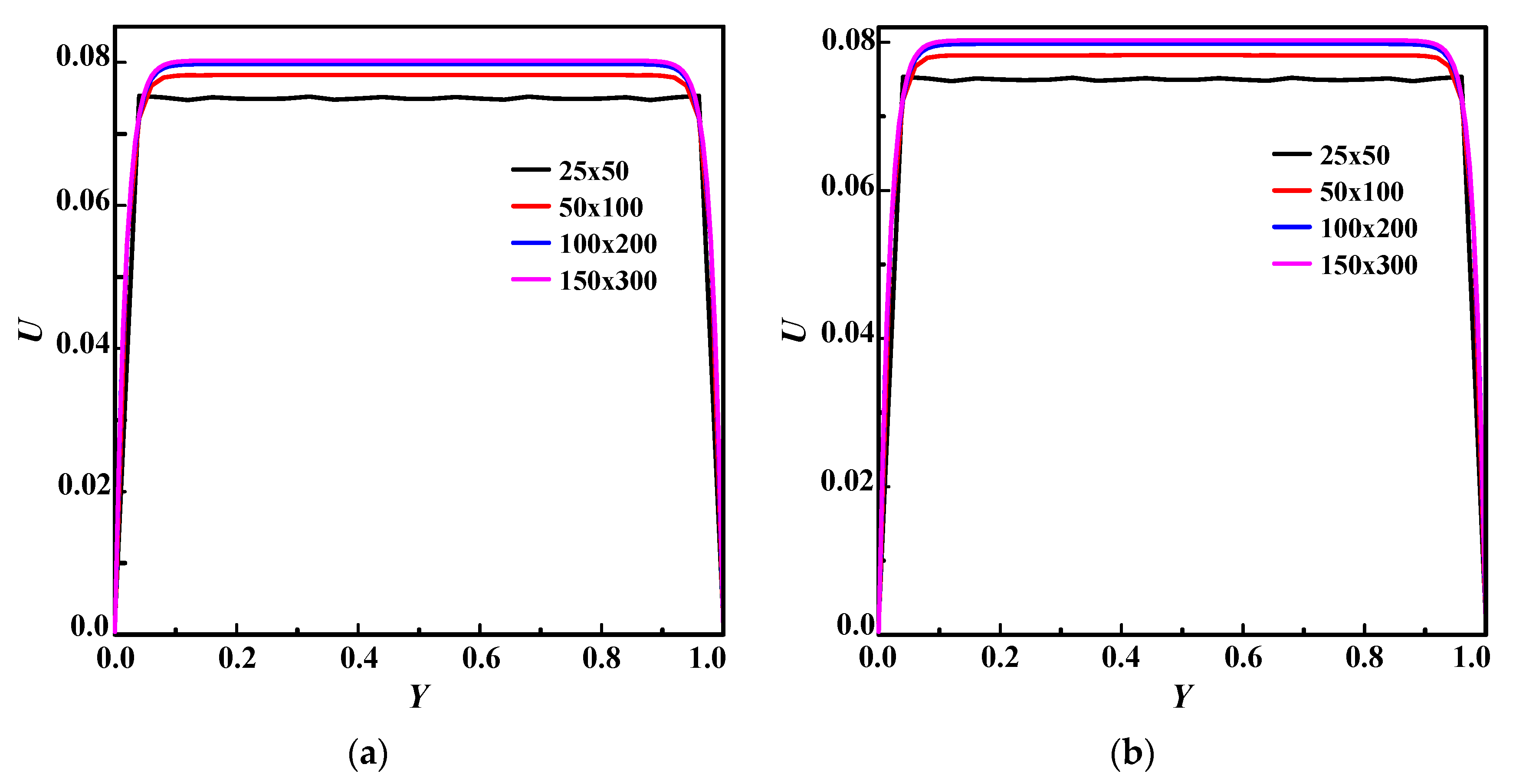
As the grid independence test is of the utmost matter to assess the numerical results accuracy, a grid independence study has been conducted using four different grids, viz.,
and
for the two deemed cases herein (see
Figure 1) for PPI = 30;
, and Re = 400 to decide on the most suitable grid number. The test is performed by computing the dimensionless U-velocity vs. the widthwise distance, as depicted in
Figure 5. It turned out that the maximum error between the 25 × 50 and 50 × 100 grids is about 7.7%. Then, the grid was refined, and the error was dropped to 1.2% between 50 × 100 and 100 × 200. Such a process was pursued to note only a minimum deviation of 0.43% between the 100 × 100 and 100 × 200 grids. Thereby, we opted for the third grid for the subsequent simulations.
The effects of the pores’ density ( and 60) and the Re number (200 and 400) will be investigated in the following sections whereas the Prandtl, Stephan, and Eckert numbers are kept fixed throughout this study. Explicitly, these numbers are set, respectively, to: (for case 1) and (for case 2).
4.2. PPI’s Effect on the LTNE Intensity for Both Cases
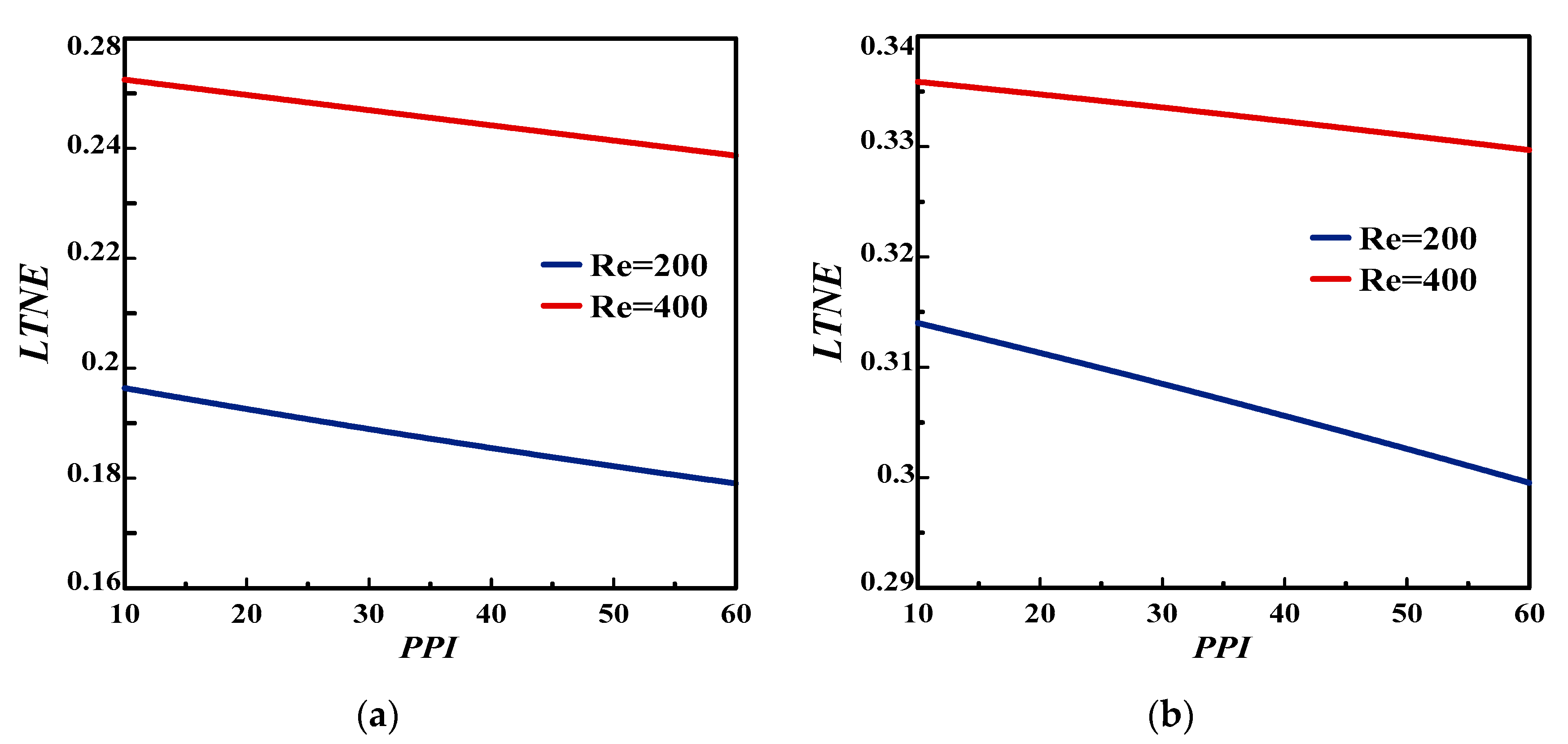
The effects of the pores’ density
(
) on the LTNE intensity are exhibited in
Figure 6 and
Figure 7 for Re = 200 and 400 during both charging and discharging processes. The results show that this parameter has a significant effect, especially at Re 400. As can be seen (
Figure 6), the LTE assumption could be adopted during the charging process for case 1, since
[
49,
51], 0.05 being the limit value allowed so that the LTNE can be conjectured. This obviously cannot be for case 2 (
) whatever PPI and Re. However, during the discharging process (
Figure 7), the LTNE intensity is secured for both cases while decreasing with increasing PPI, regardless of Re.
4.3. PPI’s Effect on the Dimensionless U-Velocity and Streamlines for Both Cases
Figure 8 and
Figure 9 exemplify the PPI’s effect on U-velocity and streamlines for the two cases 1 and 2. During the charging process, it is clear from these figures that the velocity distribution displays an approximately similar shape in both cases. In addition, it appeared that the PPI increase flattens the velocity distribution, indicating that the permeability (or Darcy number) inside the channel is decreasing.
4.4. PPI’s Effect on the Dimensionless Intensity () for Both Cases
Figure 10 and
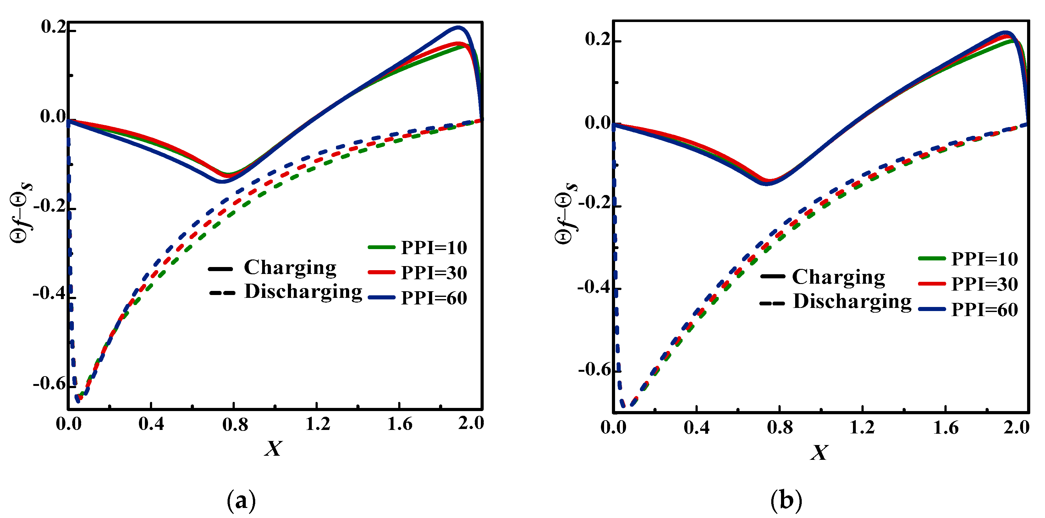
Figure 11 depict the PPI’s effect on dimensionless intensity (
) during two processes for both cases. As can be seen, the temperature profiles exhibit completely different shapes for latent and sensible heat cases. It is observed that during the charging process, the temperature intensity decreases to X = 2/5 of the channel and then increases until it reaches its maximum near the channel exit before decreasing further due to the channel cold exit. This is because the temperature of the metal is higher than that of the paraffin in 2/5 of the channel due to the high thermal conductivity of the metallic foam, thereby revealing the dominance of the forced convection. From there, the paraffin temperature rises faster than that of the foam (melting phase) to drop at the channel exit due to the forced convection weakness to the detriment somewhat of the particles’ thermal conduction, which is accentuated. In both cases, it appears that this effect remains slight regardless of the process nature (loading or unloading). As for the second case under the charging process, the temperature constantly rises with the PPI and decreases at the channel end where the two temperatures equalize, implying that the LTE assumption can be cited between the foam and water. In addition, for this model (
Figure 11), the fluid temperature generally remains higher than that of the solid, indicating that it is the thermal conduction mode that predominates. Simply stated, an increase in the PPI value inhibits (hampers) forced convection. During the discharge process, the PPI has practically no effect in the second case, the profiles being very close to each other.
4.5. PPI’s Effect on the Dimensionless Entropy Generation Rate for Both Cases
When dealing with a system stability, estimating the irreversibility generated can prove propitious and serve as an indicator.
Figure 12 and
Figure 13 outline the dimensionless entropy generation rate (
) during charging/discharging periods for both cases. As displayed in these figures, the entropy generation rate is usually the highest for a larger PPI (=60) in both cases. Moreover, from Re of 400 and PPI of 60, the dimensionless entropy generation rate reaches its maximum, indicating that forced convection is the dominant mode. However, during the discharging process, and from halfway through the channel, Ns drops as the PPI increases, since forced convection gradually gives way to conduction. Likewise, this rate is always higher (of the order of 10 times) in case 1 than in case 2. According to the amplitude of Ns, it appears that the sensible heat system is more stable than that with latent heat. To sum up, to reduce the irreversibility of the system, low values of the PPI and the Re number may be appropriate during the charging case, while a higher PPI may be helpful for the discharging case.
The evolvement of the mean entropy generation rate (
) in the systems considered with the pores density
is plotted in
Figure 14 and
Figure 15 at the selected Re numbers and for both processes. It may be noted that during the charging process, the average entropy raises with the PPIs for both models, while during discharging process, it drops when the PPI increases. In addition, it should be noted that the sensible heat system’s irreversibility is always lower compared to that of the latent heat system during the two periods.
According to the impacts discussed above, it appears that for the two models, a high porosity (=0.9) and a moderate or even low PPI must be sought to mitigate the system irreversibility during the charging process, while a larger PPI (=60) would be suitable for the discharging process.
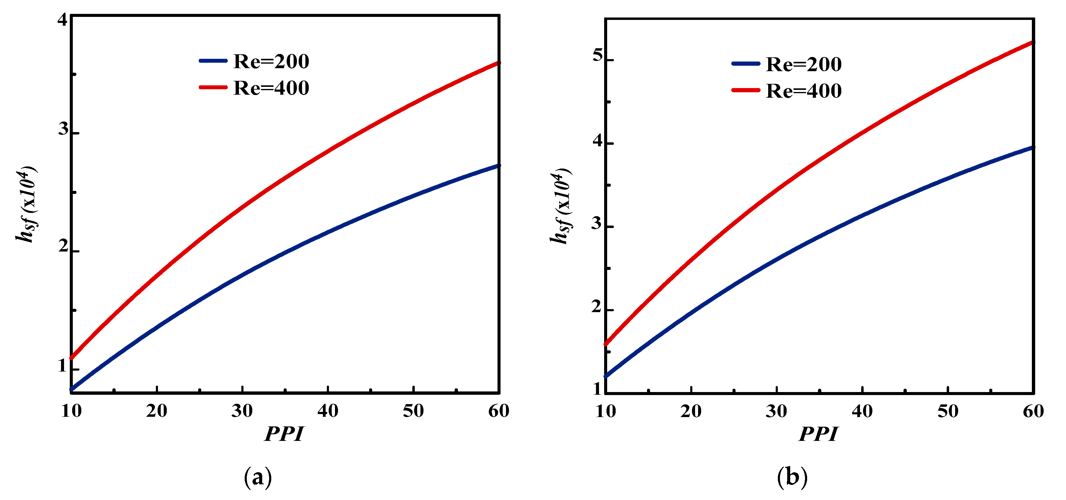
4.6. PPI’s Effect on the Interfacial Heat Transfer Coefficient () for Both Cases
The analysis of PPI’s effect on the interfacial heat transfer coefficient (
) between the metal foam/paraffin on the one hand and the metal foam/water on the other is conducted on the basis of Equation (12).
Figure 16 compares this effect between the two considered cases. It can be seen that
increases with the considered PPI and Re and reaches its maximum in both cases for high values of Re (=400) and PPI (=60). So, an increase in Re number improves the interfacial heat transfer coefficient, which highlights the conduction of heat between solid and fluid particles. This demonstrates that the forced convection in the channel generates a significant heat transfer between the particles, which contributes to the rise in the thermal conduction of the metallic foam. It can be stated that the
’s values for the sensible heat are larger than those for latent heat due to the high intensity values between metal and water than those between metal and paraffin (this is in accordance with
Figure 6 and
Figure 7). Thereby, as
increases, the solid and fluid phases converge for high PPI (=60), and then, the LTNE decreases in the overall system for this PPI’s value.
4.7. PPI’s Effect on the Performance Indicator for Both Cases
It is admitted that the systems assessment would be complete when the energy and exergy analyzes are estimated. So, to illustrate a performance indicator such as energy efficiency,
Figure 17 portrays the PPI’s effect on the energy efficiency for the considered Re. It is found that the decrease in Re number enhances the performance of the two considered systems. During the processes of the first model (phase change phenomenon), the increase in PPI from 10 to 60 for
improves the system performance (
) with an increase of about 2% for Re = 200 and 400. However, for the second model (sensible heat), the overall energy efficiency decreases with 3.6% for Re = 400 and 1.3% for Re = 200 for the PPI’s variation from 10 to 60. It may be noted that the LHTESSs are more useful than SHTESSs to pick up the maximum energy.
It should be pointed out that systems exergy evaluation (including thermal losses) imparts the thermodynamic estimation of the energy stored quality because it considers the pros and cons of heat availability through these systems. As shown in
Figure 18, it can be seen that the Re decrease improves the exergy efficiency for the models considered due to the two systems’ irreversible decrease (see
Figure 14 and
Figure 15). For the first model, the exergy efficiency increases from 29.1% (PPI = 10) to 50.3% (PPI = 60) with the PPI for Re = 200. However, for Re = 400, it increases from 21.5% (PPI = 10) to 29.2% (PPI = 60). Simply put, it can be stated that an increase in PPI promotes the rate of latent heat transfer and the melting process. As for the second model, the exergetic efficiency exhibited ascending profiles vs. the PPI’s values, thereby contradicting with the energetic analysis. This explains the significant thermal losses for low PPI’s values (
) for SHTESSs. In addition, as PPI increases (
), the energy damage is reduced due to the system stability. To sum up, it turned out that the first model generally provided higher exergy efficiency than the second model.
5. Summary and Conclusions
The present study dealt with the metal foam pore density effect on sensible and latent heat storage through an enthalpy-based TLBM during charging/discharging processes at two Re numbers of 200 and 400. The porous medium effects at the REV scale and based on the DBF model are incorporated in the equilibrium distribution functions and Boltzmann’s equation. The investigation was performed in an open-ended channel incorporating a porous medium filled with either a PCM or water. Streamlines, velocity and thermal fields, LTNE intensity, entropy generation rate, interfacial heat transfer coefficient, and performance indicators such as energetic and exergetic efficiencies were exhibited. These findings provided some insights into the targeted parameters effects.
From the results thereby obtained, it should be stated that the enthalpy-based REV-TLBM approach has great potential in simulating the phase change in a porous medium under the flow unsteady conjecture and the LTNE constraint, during the charging process, is not valid for case 1, unlike the second. However, during the discharging process, such an assumption proved to be valid for both systems while evolving inversely with the PPI variation. As far as the charging process is concerned, increasing the PPI decreases the permeability within the systems and thereby flattens the velocity shape. Furthermore, it raises the temperature intensity while mitigating the forced convection for both systems.
For the first case, forced convection prevails at the channel’s beginning during the charging process followed by the conduction mode, while thermal conduction dominates almost everywhere in the second case. However, during the discharging period, the PPI variation is proportional to the temperature intensity for the first case, but it has no effect in the second.
To improve the thermal performance of the cases deemed, the system irreversibility (in both cases) can be mitigated via a low PPI (=10) during the charging process, while a high value (PPI = 60) can be advised during the discharging process. In addition, for both cases, the values of the energy and exergy efficiencies obtain an optimum value at low Re number. Meanwhile, the intensification of PPI lessens energy losses for sensible heat systems and thereby raises the stored energy quality.
To sum up, the obtained findings provide some novel implications on the simulation of phase change in a porous medium under unsteady flow with LTNE. Likewise, they can be useful in the design of LHTES and SHTES systems.


