
A Data Management Approach Based on Product Morphology in Product Lifecycle Management

1
School of Mechanical Engineering, Shandong University, Jinan 250061, China
2
Key Laboratory of High Efficiency and Clean Mechanical Manufacture, Ministry of Education, Shandong University, Jinan 250061, China
3
School of Control Science and Engineering, Shandong University, Jinan 250061, China
*
Author to whom correspondence should be addressed.
Processes 2021, 9(7), 1235; https://0-doi-org.brum.beds.ac.uk/10.3390/pr9071235
Submission received: 27 May 2021
/
Revised: 8 July 2021
/
Accepted: 13 July 2021
/
Published: 16 July 2021
(This article belongs to the Special Issue Process Control and Smart Manufacturing for Industry 4.0)
Abstract
:In the product life cycle from conception to retirement, there are three forms: conceptual products, digital products and physical products. The carriers of conceptual products are requirements, functions and abstract structures, and data management focuses on the mapping of requirements, functions, and structures. The carrier of digital products is digital files such as drawings and models, and the focus of data management is the design evolution of product. Physical products are physical entities, and their attributes and states will change over time. Existing data model research often focuses on one or two forms, and it is even impossible to integrate three forms of data into one system. So, a new data management method based on product form is presented. According to the characteristics of the three product form data, a conceptual product data model, a digital product data model, and a physical product data model are established to manage the three forms of data, respectively, and use global object mapping to integrate them into a unified data model. The conceptual product data model has a single data model for a single business stage. The digital product data model uses the core data model as the single data source, and uses one stage rule filter to add constraints to the core data model for each business stage. The physical product data model uses the core data model to manage the public data of the physical phase, and the phase private data model focuses on the private data of each business phase. Finally, a case of Multi-Purpose Container Vessel is studied to verify the feasibility of the method. This paper proposes three product forms of product data management and a unified data management model covering the three product forms, which provides a new method for product life cycle data.

1. Introduction
With the coming of global economic integration, a deep affinity exists for the manufacturing industry. Customers focus not only on high quality and low cost, but also on innovation, service, environmental protection and the personalization of products. Thus, manufacturers must pay attention to intellectual capital, from a product’s initial conception to its retirement.
Product Lifecycle Management (PLM) is defined as “A strategic business approach that applies a consistent set of business solutions that support the collaborative creation, management, dissemination and use of product definition information” [1]. In this decade, PLM systems are recognized for managing the information of the full product lifecycle [2].
A critical aspect of PLM systems is their product information modelling architectures [2,3]. A reasonable and effective product data model can seamlessly integrate and make available all of the product data throughout all of the phases in a full lifecycle, to the right people, who are the manufacturer, suppliers, facilitators, customers and circulation economy enterprises, at the right time.
In the product life cycle, products have three morphologies: conceptual products, digital products, and physical products. The carrier of a conceptual product is an abstract product structure oriented to product requirements and functions. Conceptual product data management focuses on the realization relationship between requirements and functions, and functions and structures. The carrier of digital products is data based on the product design structure, including the attributes of the product and its parts, two-dimensional drawings, three-dimensional models, instructions, analysis reports and other data. The focus of digital product data management is product evolution management. Physical products are physical objects that really exist, and can be used and maintained. Physical product data management focuses on changes in product status and attributes over time. The data management characteristics of these product morphologies determine that there are huge differences in data management modes, and there is a gap.
In this paper, a new product data management method based on product morphology is proposed. The method uses three data models and integrates the three data models into a data management framework to manage product lifecycle data. The first one is a single data model for the conceptual data. The second one uses a core data model and several phase rule filters for the digital data. Additionally, the last one includes a core data model and several phase private data models for the physical data. This approach removes the gaps among the conceptual product, digital product and physical product, which are divided according to product morphology. Thus, all the product data seamlessly integrates into one system.
The structure of this paper is as follows. Section 2 studies the state-of-the-art of a data model in PLM. Section 3 discusses the methodology. Section 4 presents three product morphology types: the conceptual product, the digital product and the physical product. Section 5 achieves a Unified Data Model based on Product Morphology (UDMPM) using Unified Modelling Language (UML). Section 6 studies a case of shipbuilding to validate the data management approach.
2. State-of-the-Art: A Data Model of PLM
In this section, several types of product data modelling methods are reviewed. The researchers studying the product data model focus on different aspects to deal with the problems facing them. Then, different methods of product data description and expression, integration of multi-phase data, single data source and so on are presented. The emphases of them are as follows:
The description and expression of product data describe products in terms of content, attributes, and relationships, which are the basis of data management. There are many related studies, mainly focusing on the following four aspects. (1) Meta-data and meta-model are used for product data modeling and integration. Xia uses meta-models to describe data in the stages of product design, process manufacturing, sales operations, and maintenance [4]. Kreis uses meta-data to describe CAD data and integrates with PDM systems [5]. Tao uses meta-models to describe the basic structure and content of the data set, enables the retrieval and integration of heterogeneous data from different data sources [6]. Dinesh uses meta-models to support the integration of CAD, CAPP, NC tool path verification and MRP systems [7]. (2) Ontology is an explicit and formalised description of common concepts [8,9]. Ontology-based data models are used for product design, production, use, and service data management and integration [10,11,12], as well as product knowledge [13]. (3) As the most popular data exchange format and data model language, eXtensible Markup Language (XML), Standard for the Exchange of Product Model Data (STEP) and UML were widely adopted in data modelling. XML presented shared data to different information systems [14,15]. STEP was used as a bridge to integrate heterogeneous data [16,17,18]. UML model administrates product data [4,19]. (4) Product Profiles are multiple benefit models that benefit expected suppliers, customers, and users, and are used for the description and expression of early conceptual product data. Roughly outline the outline of the product, for example, with basic product attributes, customers can experience the functions of future products without completely predicting its shape [20].
The integration of multi-stage data is another research focus. Product plan-BOM (Bill Of Material), design-BOM, craft-BOM, stock-BOM, manufacture-BOM, finance-BOM, customer-BOM, and after service-BOM, is integrated to supply a single data source by developing a data flow [21,22]. Li uses data domains integrating a concept design domain, a structural design domain, a detailed design domain, a process planning domain, a manufacturing domain and a sales and service domain by mapping [3]. Xia puts forward a unified meta-model that supports the data meta models in the stages of product design, process manufacturing, sales and operation, and maintenance services [4]. Cai analyses the main mapping forms of BOM multi-views and designs the mapping rules of BOM multi-view model [23]. A dynamic BOM describing the configuration of a spacecraft assembly indifferent phase of product development is established [24]. Modular instance structure data models of the generalized product are established, and the structure mapping views in different phases of the product life cycle are also presented [25].
A single data source is the next focus. Single data sources guarantee consistency, integrality and security of data to the largest extent. A single data source is obtained by integrating multi-BOM [26]. Sudarsan described a product information-modelling framework, based on the NIST Core Product Model (CPM) and its extensions: The Open Assembly Model (OAM), the Design-Analysis Integration model (DAIM) and the Product Family Evolution Model (PFEM), which can support the full range of PLM information needs [2]. A configurable BOM model abstracts key entities such as product, product attribute, material, material attribute, material brand, is a single data source of product parameter calculation [27].
All the researches above have contributed to information modelling of PLM. However, there are some problems that remain to be solved:
Product data description and expression model one or several stages of product structure, attributes, characteristics and documents. However, it is not a deeper factor, that is, product form. It is the most critical factor for product existence and data evolution. Different product forms have different carriers and data evolution patterns, while the carriers and data evolution patterns at different stages in the same product form are the same. Therefore, a data model that does not take into account the similarities and differences of product form and product stage cannot well manage all product data and its evolution, and support data tracking throughout the life cycle.
Integration of multi-phase data uses complex mapping relations and brings redundant data among multi-BOM, multi-phase data models or multi-domains. The consistency and integrality of product data are usually out of control throughout the course of full lifecycle. Additionally, upward spread of versions is enlarged. Most studies only achieve the integration of conceptual products and digital products or digital products and physical products. BOM or domains of different stages are regarded as the same concepts as each other. The evolution process of “conceptual product”, “digital product” and “physical product” has not been described.
Single data sources achieve a single meta-model, a single data model of the design phase or multi-phase data models and multi-BOM, which are not one whole data model. It either cannot express all of the information on a product from concept to retirement, or it is too difficult to implement.
To manage data from the full lifecycle, the paper studies product morphology, and a unified data model is presented. The morphology of a product has three types: a conceptual product, a digital product and a physical product. Every product morphology type has a meaning, a function, and data. According to the characteristics of the product morphology type, the unified data model reveals the three product morphology types and their relations.
3. Methodology
The product life cycle covers the entire process of a product from concept to death, including many business stages. Collecting and analyzing the data of each stage, it is found that the carrier of the product has three forms. Summarizeing the three product forms revealed the differences between them, and we have summarized the characteristics of data evolution.
Facing each product form, studying the characteristics of each phase of the product, it is found that the logical relationship of the data within the product form is similar, and there is an evolutionary relationship between the data in each phase.
Based on the different characteristics of the data evolution of each product form, the data model of each product form is established as a single data source, reducing the mapping relationship between BOMs, reducing data redundancy and the complexity of data management, and it is easy to maintain data consistency. Then, the mapping relationship of global objects is established to achieve the morphological evolution path of “conceptual product” to ”digital product” to a ”physical product”.
UML supports object-oriented technology, can express various objects and their attributes concisely and clearly, can describe rich relationships in data modeling, and is used to establish a unified data model.
4. Study of Product Morphology
A product is a thing that is produced to meet the demands of a customer. There are three product morphology types in a lifecycle: a conceptual product, a digital product and a physical product, which separately are the forms of a concept, digital data and an entity with matter.
A conceptual product is an abstract concept that describes the inherent characteristics of a type of product. It is the result of product conceptual design, and its carrier is the product requirement, function and abstract structure. Conceptual products are the source of product evolution, from which products of different models and specifications can be developed.
A digital product is developed based on conceptual products, which define the detailed functions, structural composition, structural features of parts and components, production processes and materials of the product. Its carrier is product structure information, two-dimensional drawings, three-dimensional models, calculation instructions, simulation analysis data, etc. The product structure is a framework for organizing and managing other data, which exhibits EBOM, PBOM and MBOM. Product data are gradually improved and accurate along with the development process. Versions are used to manage data evolution.
A physical product, also called an instance product, is a physical entity that can be manipulated. It has use value and can truly meet the needs of customers. It exists in a specific time domain and space domain, and its use and management are restricted by time and space. It has a single structure, but its properties and status change over time. The PLM system manages the data extracted from the physical product, including product attributes, status and structure. The above data has time series properties and is unique at a certain moment.
In summary, the conceptual product, digital product and physical product are different morphology types of the same product, and separately involve conceptual, digital and physical things. There are many studies that concern data model of a digital product and a physical product, but, importantly, do not include a conceptual product.
5. Unified Data Model Based Product Morphology
There are large differences in the data of the three product morphology types. The data of a conceptual product is abstract and general, and includes concepts, functions and main structures of multi-series products. The data of a digital product is accurate and changeable, and includes structural data, attributes, requirements, and processes. The structural data of a physical product is usually changeless, and some attributes and states change continually.
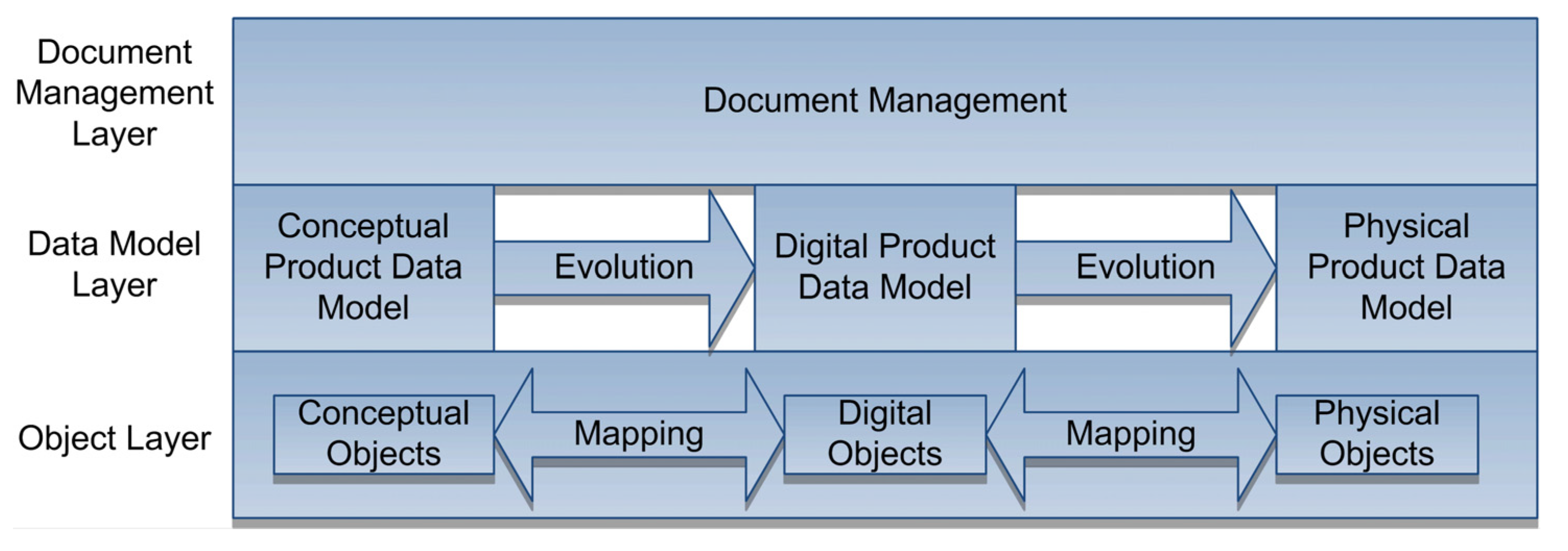
According to the differences above, the Unified Data Model based Product Morphology (UDMPM) is made of three layers: Object Layer, Data Model Layer and Document Management Layer, as shown in Figure 1. The Object Layer includes an object pool, which creates and destroys Conceptual Object, Digital Object and Physical Object and manages the evolution among the three types of objects by mapping. The Data Model Layer holds three data models: the Conceptual Product Data Model (CPDM), the Digital Product Data Model (DPDM) and the Physical Product Data Model (PPDM). The three data models separately manage the data of three product forms and support corresponding business applications, acting as single data sources of every product morphology type. Document Management manages all of the unstructured data in the full lifecycle. UDMPM is based on UML. UML is an effective PLM modelling language and supports a Model-Driven Architecture (MDA). Thus, UML can achieve a platform-independent model.
5.1. Object Layer
The object layer uses an object pool to create and destroy all of the business objects and manages mapping relations among the conceptual object, digital object and physical object. The conceptual object, digital object and physical object are separately the abstract of business objects of a conceptual product, digital product and physical product, including the products, components, parts, functions, requirements, resources and so on. A conceptual object is the source of several digital objects. Many physical objects are derived from the same digital object. Thus, there are mapping relations that describe the evolution of the three objects.
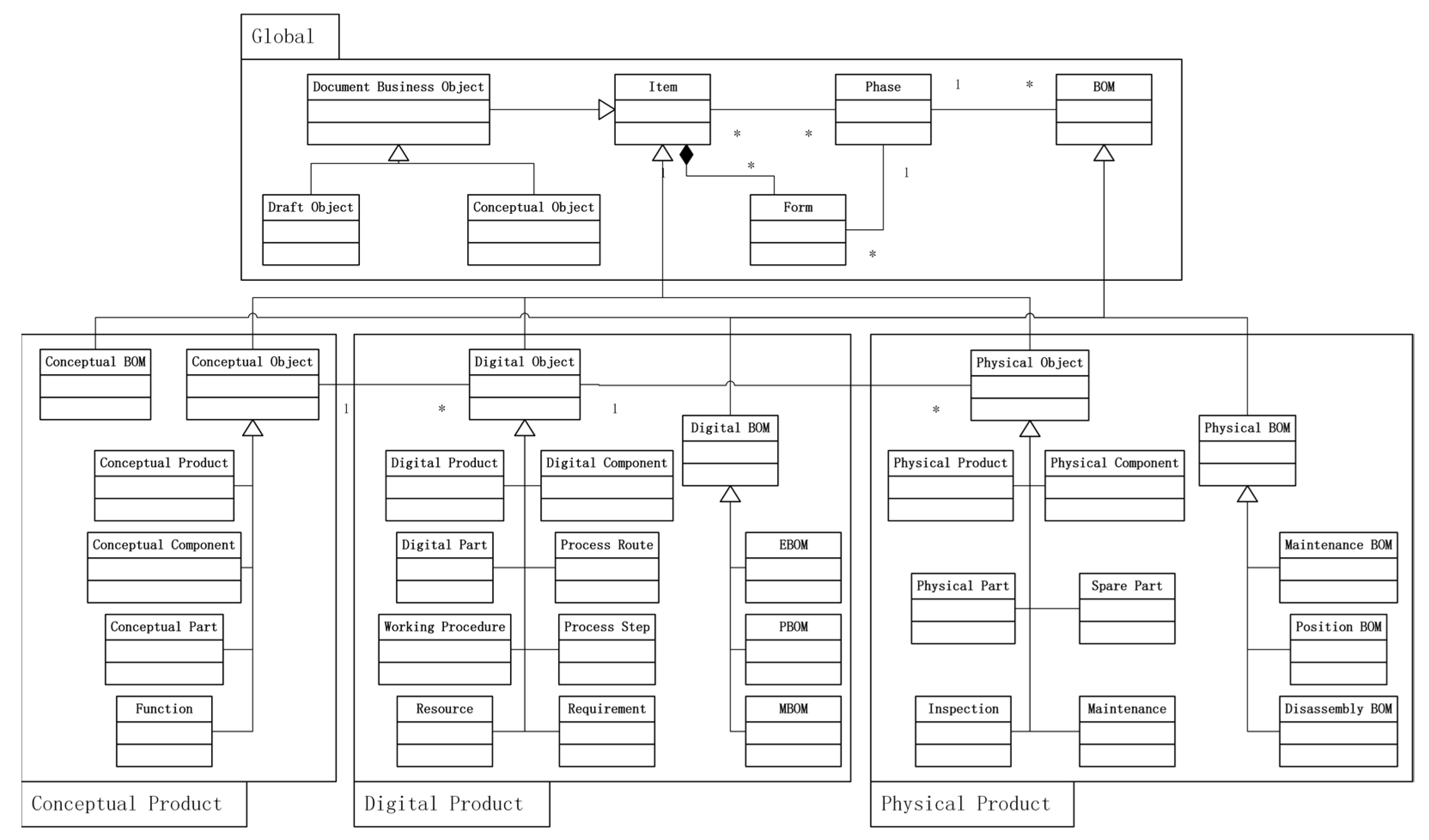
A UML static class structure of all product objects is presented and divided into four groups: Global Objects, Conceptual Product Objects, Digital Product Objects and Physical Product Objects, as shown in Figure 2. As shown in Figure 2, symbol 1 and symbol * represent the one and multi-object, respectively.
Global Objects are the base of all objects. Item is the base class of all the business classes, and BOM is the base class of all the types of BOM objects. They are abstract classes and cannot be instantiated. The subclass of Document Business Object and Document Dataset are used in document management. The main attributes of Item, such as ID, name, revision, vision, security classification, type, owner and time, are managed alone, and other phase-attributes are managed by Form. Phase is the abstract of the business phase. Some subclasses of Item can exist in several Phases, for example that the same products, components and parts are in requirements management, structure design, process design and so on. However, Form and BOM only belong to a Phase. Then, Item can integrate the attributes and structural information of a multi-phase and can hold the access of every phase.
The main subclasses of Item are Conceptual Object, Digital Object and Physical Object, which are basic abstract classes of three product morphology types and cannot be instantiated.
Conceptual Object and Conceptual BOM are major Conceptual Product Objects. Conceptual object is a super-class of all of the conceptual product business objects and has the attributes: state (Working, Modifying, Examining, Released and Invalid) and project. Its major subclasses are Conceptual Product, Conceptual Component, Conceptual Part and Functions, which are the abstracts of corresponding business objects and have attributes, as shown in Table 1. Conceptual BOM is an accessorial class creating the relations of two objects in the conceptual product structure tree. The data model of Conceptual Product is composed of the four subclasses, Conceptual BOM and other Conceptual Product objects, which are derived from Conceptual Object to fit specific needs.
Digital Object and Digital BOM are major base classes of Digital Product Objects. Digital Object is a super-class of all of the digital product business objects and has the attributes: state (Working, Modifying, Examining, Released and Invalid), project, maturity degree and employ degree. Its subclasses are Digital Product, Digital Part, Digital Component, Process Route, Working Procedure, Process Step, Requirement, and Resource, all of which have unique attributes outlined in Table 2. Digital BOM also is an accessorial class, and its subclasses are EBOM, PBOM, and MBOM. All of the subclasses above establish digital product structure.
Physical Object and Physical BOM are major base classes of Physical Product Objects. Physical Object is a super-class of all physical product business classes. The subclasses of Physical Object are Physical Product, Physical Component, Physical Part, which have attributes as shown in Table 3. Physical BOM is an accessorial class also, and its subclasses are Maintenance BOM, Position BOM and Disassembly BOM. All of the subclasses above construct a physical product structure.
5.2. Data Model Layer
According to the data characteristics of every product morphology type, Data Model Layer uses corresponding objects when building data models, including CPDM, DPDM and PPDM. The three data models are single data sources of every product morphology type. Mapping relations combine three data models into a whole model and remove the gaps among them.
CPDM, DPDM and PPDM are separately composed of a core data model and phase data models. A core data model is the real single data source of product morphology types and assures the uniqueness and consistency of the data. A phase data model is a logic data model that exhibits the data of a core data model for business applications in a specific phase.
5.2.1. Conceptual Product Data Model
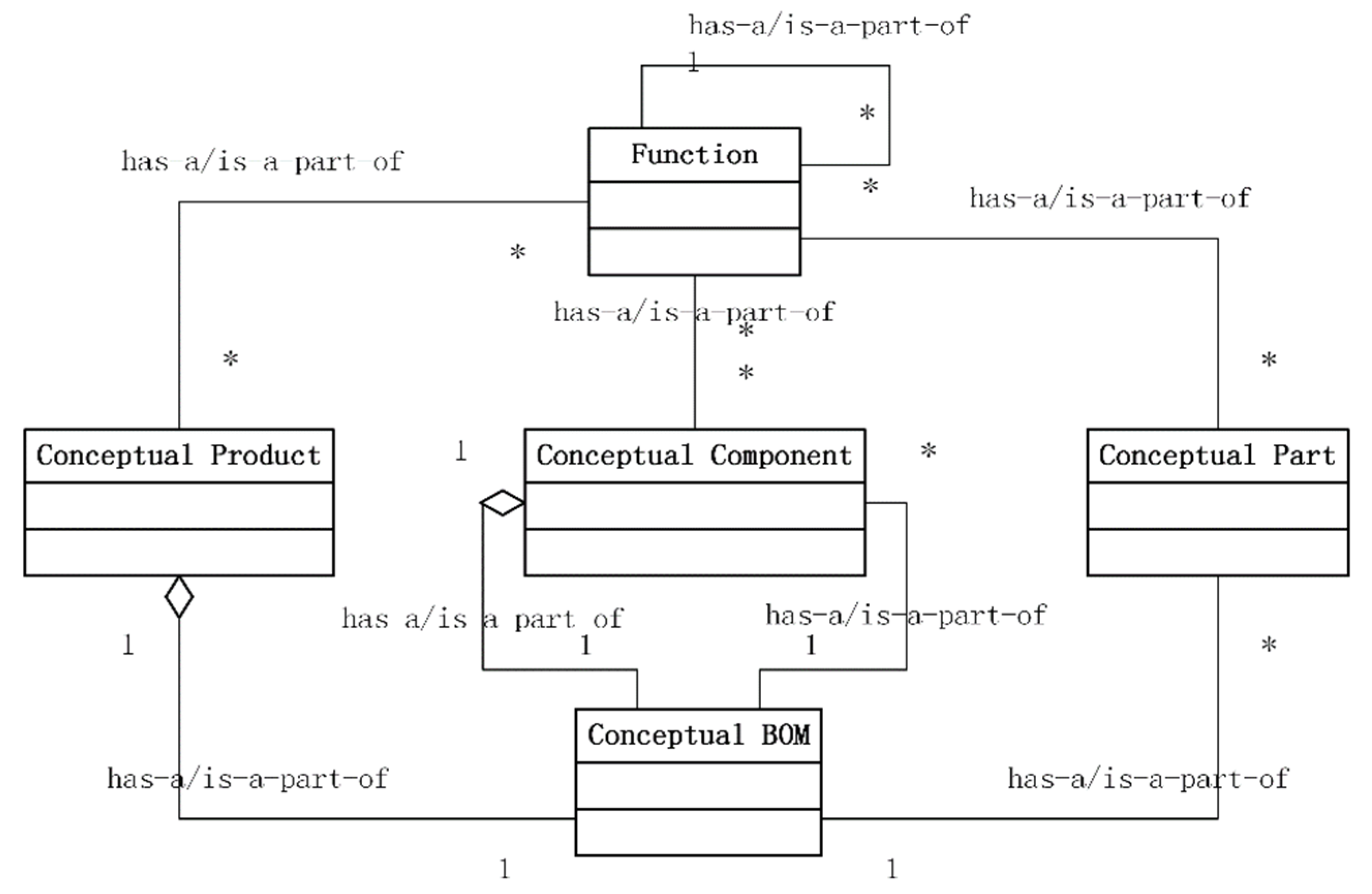
CPDM achieves Function–Structure management, and a Conceptual Core Data Model (CCDM) is the same as a Conceptual Phase Data Model (CPhDM), because there is only one phase. CPhDM is shown in Figure 3. The Conceptual Product and Conceptual component have a Conceptual BOM. At the same time, a Conceptual BOM has several Conceptual Components and Conceptual Parts. With the help of Conceptual BOM, the structure of a Conceptual Product is built. Conceptual Product, Conceptual Component and Conceptual Part have several Functions, and the Function structure is a tree.
5.2.2. Digital Product Data Model
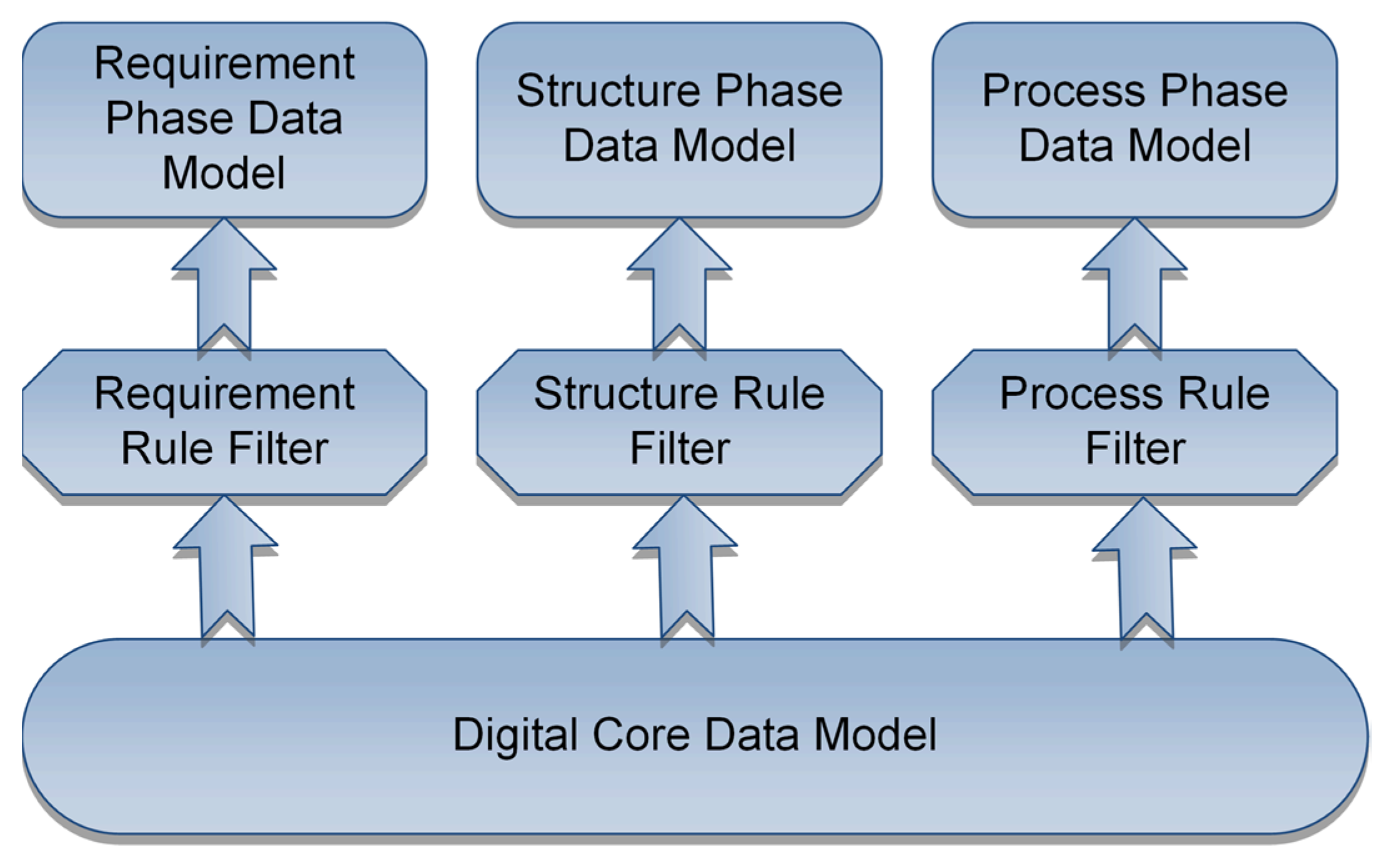
Digital product evolves through several business phases, including requirements management, structure design, process design and so on. DPDM, including a Digital Core Data Model (DCDM), multiple rule filters and phase data model, is presented, as shown in Figure 4. DCDM is the only data source of a digital product, and flexibly manages all of the design data. There is a rule filter that adds constraints to DCDM in every business phase to prevent illogical and unauthorised operations, and then, the phase data models appear. Rule filters are in phase business managers; for example, Structure Rule Filter (SRF) is in Product Structure Editor, which is a tool that manages design structures. In the digital product, there is Requirement Rule Filter (RRF), SRF, Process Rule Filter (PRF) and Requirement Phase Data Model (RPDM), Structure Phase Data Model (SPDM), and Process Phase Data Model (PrPDM).
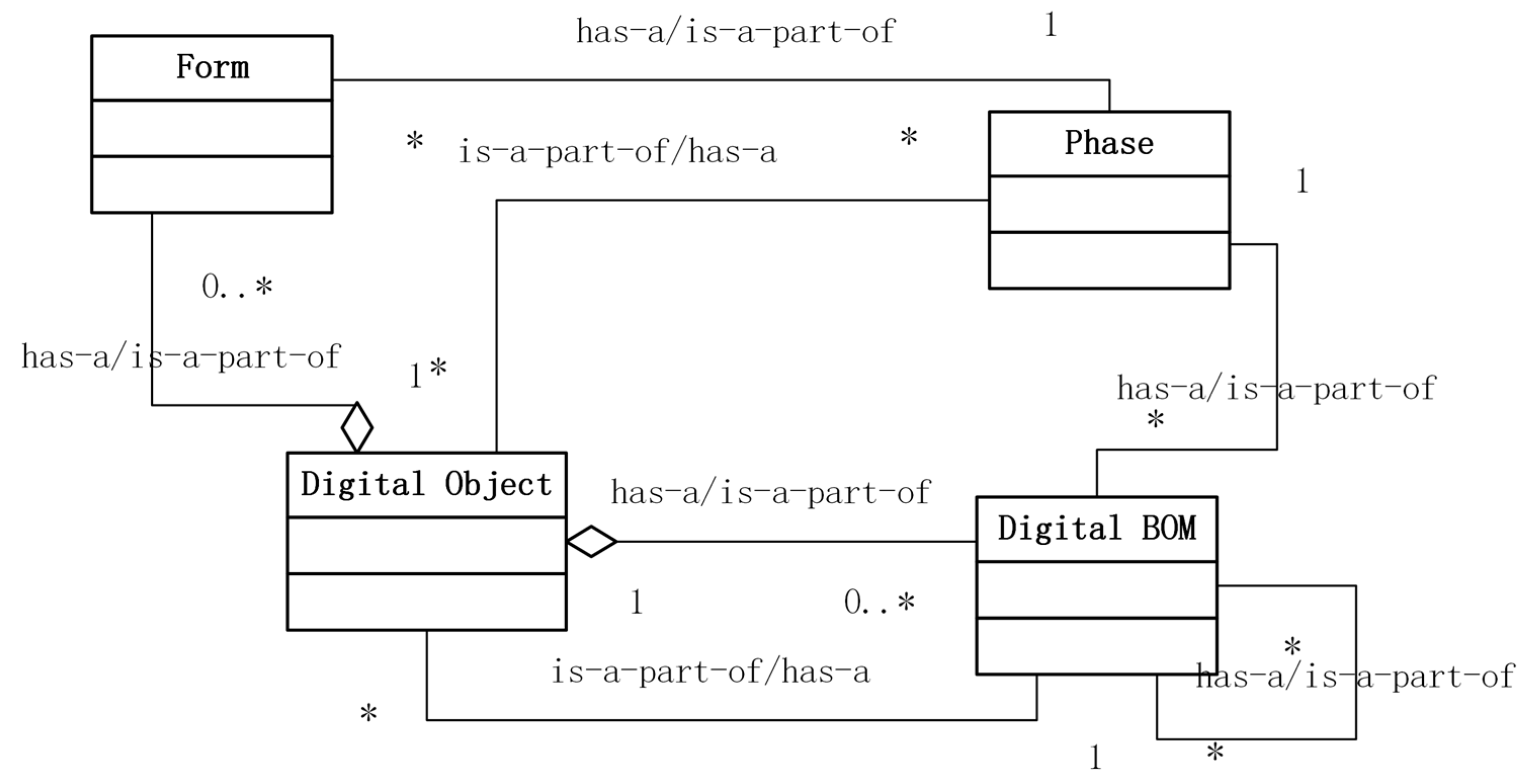
DCDM is very flexible for heterogeneous data and is shown in Figure 5. The digital object contains 0 or more Digital BOMs and 0 or more forms. Digital BOM manages the underlying structure of digital objects, and forms manage the attributes of digital objects at different stages. Digital objects are contained in multiple stages, indicating in which stages are valid. The stage contains multiple digital objects, multiple Digital BOMs, and multiple Forms. A stage has multiple digital objects and their part Digital BOM and Form. Form and Digital BOM belong to a Digital Object and a Phase, which means that it is the Form and Digital BOM of this object at this stage. Digital BOM has multiple Digital Objects and multiple Digital BOMs, which, respectively, indicate which objects it contains and the relationship with the underlying structure.
Rule filter uses a set of rules to restrict objects, relations and access. The attributes of the rules are shown in Table 4. In Table 4, symbol 0 represents there is no object. ID is the identification number. The name is used to indicate the meaning of a rule. Phase decides the business phase. Priority means the order of importance. Relation is the relationships between Source Object and Destination Object. Multiplicity represents the quantitative relationship between Source Object and Destination Object in the rule. Access means who has the right to use this rule.
Requirements management perfectly and accurately depicts the product capability that satisfies the demands of customers. The requirements come from a customer’s advice and complaints, orders, and development processes. They are managed and tracked by an RPDM.
In the requirements management phase, there are many rules, as shown in Table 5. The Source Objects and Destination Objects have access to this phase, while other objects do not. All of the relations permitted and their multiplicities are shown in Table 5. A Product has a Requirements BOM for managing all of the requirements. The relations between Requirement and Requirement BOM build the requirements tree. Requirements are met by Design Objects, and the relations between them are used for requirements tracking management. Requirement has several subclasses, including Customer Requirement, Usage Requirement, Sale Requirement, Management Requirement, and Technology Requirement.
The rules of the structure design stage are shown in Table 6. Design Object has three subclasses: Design Product, Design Component and Design Part. The subclass of Form is Structure Form. The subclass of Phase is Structure Design Phase. The subclass of Design BOM is EBOM. Both Design Product and Design Component have an EBOM object that manages the design structure. EBOM has multiple EBOM and Design Part, which manage the subordinate structure and the parts contained in this level, respectively. Design Product, Design Component and Design Part each have a Structure Form, which manages the properties of the design phase. There are Specification, Compose, Reference and Requirement relationships between two Design Objects. Design Product, Design Component, Design Part, EBOM and Structure Form all belong to a Structure Design Phase. The relationship between Requirement and Design Object is “Requirement/Function”.
The rules of the process design stage are shown in Table 7. Design Object has eight subclasses: Design Product, Design Component, Design Part, Process Route, Working Procedure, Process Step, Resource and Work Area. The subclasses of Process Route are Assembly Process and Manufacturing Process. The subclass of Form is Process Form. The subclass of Phase is Process Phase. Process BOM (PBOM), Bill Of Process (BOP), Bill Of Resource (BOR) and Bill Of Work Area (BOWA), which separately manage structures of process, resource and work area, are subclasses of Design BOM. PBOM is subordinate to Design Product, Design Component and PBOM, and manages a hierarchical process structure. PBOM contains Design Part, and is subordinate to Process Phase. Process Form belongs to Design Product, Design Component, Design Part and Process Phase to manage the process attributes of product, component and part. Process Phase has Process Form, Design Product, Design Component, Design Part, Process Route, Working Procedure, Process Step, Resource, Work Area, Assembly Process, Manufacturing Process, BOP, BOR and BOWA.
5.2.3. Physical Product Data Model
In contrast to a conceptual product and digital product, a physical product has individualities. The data of physical products, which are from one digital product, are not the same as each other. The structures and most of the attributes of physical products, components and parts are changeless, but the state and other attributes change frequently. Physical components and parts are replaced often. The objects of inspection, MRO and recycling are the physical object, such as the physical product, physical components and physical parts.
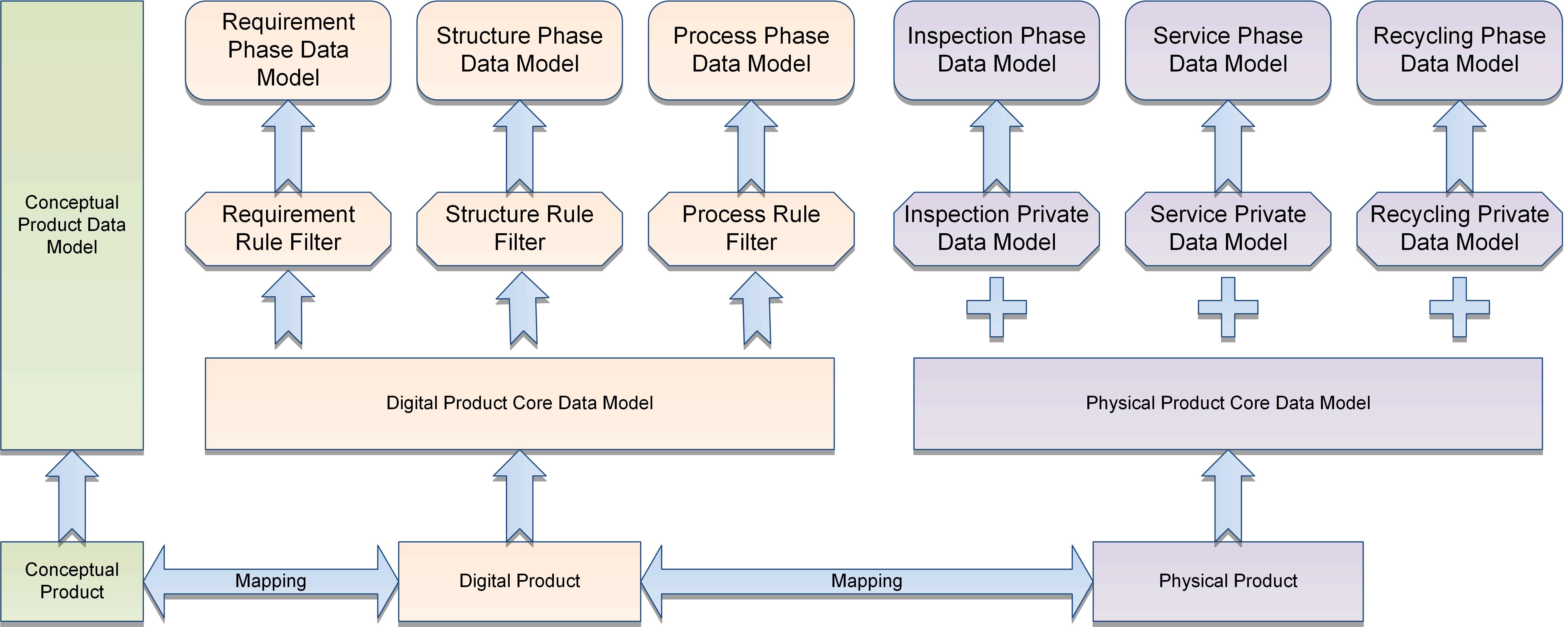
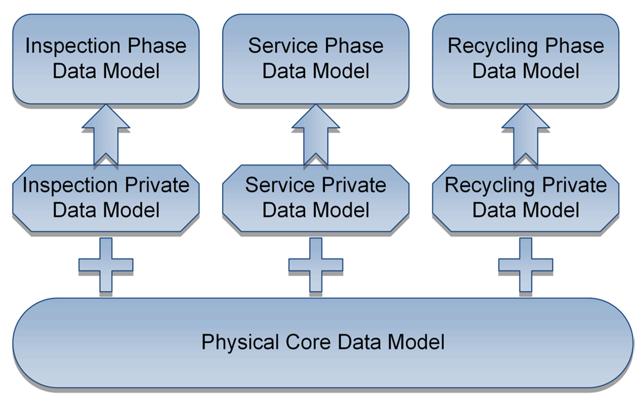
Thus, PhDM is composed of the Physical Core Data Model (PCDM) and several private data models, including the Inspection Private Data Model (IPrDM), Service Private Data Model (SPrDM) and Recycling Private Data Model (RPrDM). PCDM describes the objects, structure and attributes of the physical product. Private data models manage the private data of each phase. Phase data models are the sum of the PCDM and private data models, and there are three phase data models: the Inspection Phase Data Model (IPDM), Service Phase Data Model (SPDM) and Recycling Phase Data Model (RPDM), as shown in Figure 6.
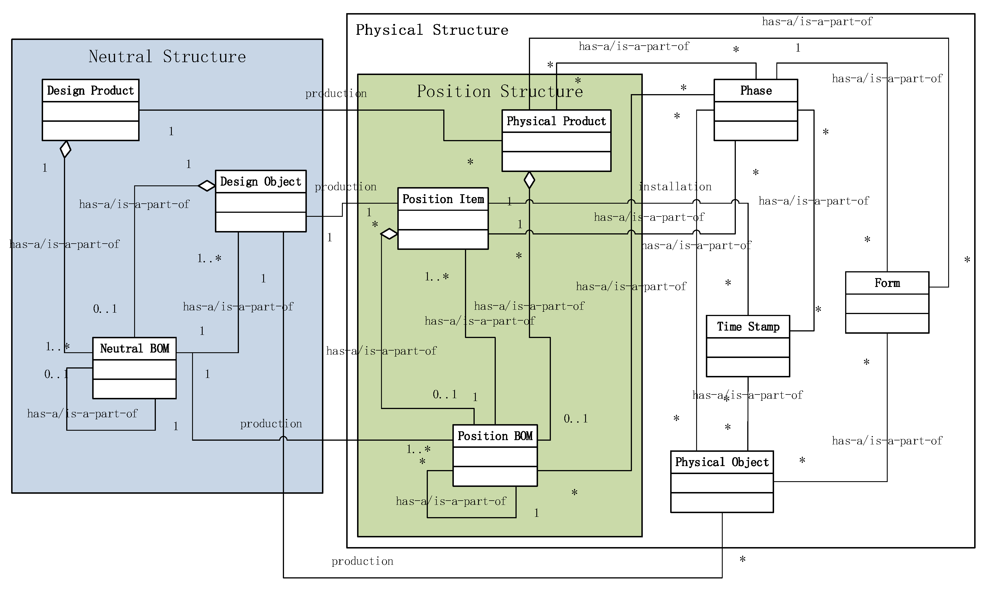
As shown in Figure 7, PCDM comprises Neutral Structure, Position Structure and Physical Structure. A digital product will produce thousands of physical products. In the maintenance phase, the attributes and status of physical products are different and will change over time. Each physical product requires a physical structure to manage attributes and status data separately. However, the design and process data of these physical products are the same, and the maintenance planning and solutions, failure modes and other data of the MRO stage are also the same. If the same data are managed with a physical structure, it will bring thousands of instances of data redundancy and easily lead to data inconsistency. Therefore, a neutral structure is used to manage the common data of physical products of the same design. Position Item inherits structural information, and Physical Object obtains other attributes from Design Object. Time Stamp stores the time relative to when Physical Object is installed on Position Item.
Neutral Structure bridges the gap between the design product and physical product and manages common structures of physical products from one batch, and it is a simplified mirror of the design structure with respect to the granularity and assembly structures in the processes of use and repair. It manages instructions, operations process, maintenance methodology and necessary design information. Design Product, other Design Object and Neutral BOM construct the Neutral Structure, such as an SPDM.
Position Structure, which is made up of Position Item and Position BOMs, mirrors the Neutral Structure and defines configuration data and position meta-data, which manage maintenance and repair documents that relate to the assembly position. Position Structure represents a virtual physical product that is independent of specific physical components and parts. Every Physical Product has a Position BOM to manage its sub-Item—Position Item. Position Item is a type of placeholder for a physical component and part in Position Structure and builds the structure with the help of Position BOM.
Based on Position Structure, Physical Structure manages the data of disassembly and assembly of specific physical components and parts with the help of Time Stamp. At any time, the structure of a physical product is extracted from Physical Structure, because one Physical Object can be installed on different Position Items, and one Position Item can use different Physical Objects at different times. However, the relations between Position Item and Physical Object are 1:0, 0:1 and 1:1 every moment. Physical Product and other Physical Objects have Forms to manage their attributes in different business phases. The phase decides where the Form, Physical Product and other Physical Objects are utilised.
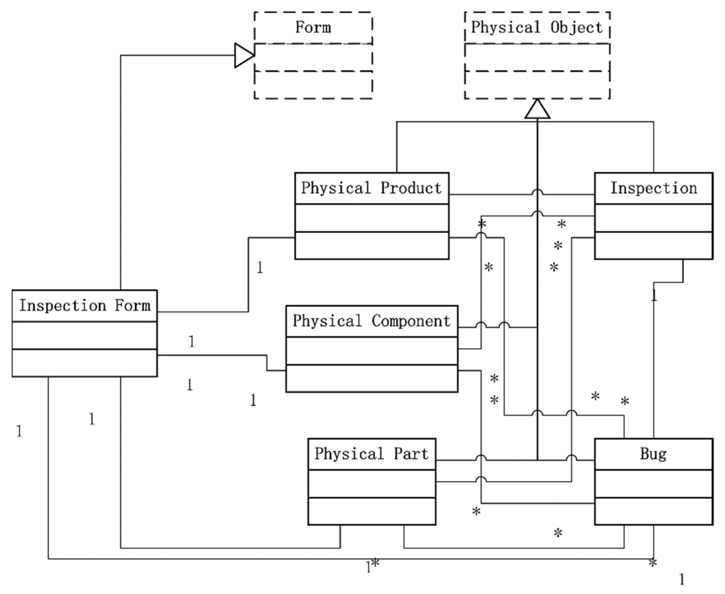
In the inspection phase, according to quality standards, a strict working process and methods are used to supervise and control the quality of a physical product and to avoid providing defective physical products to the market. The aims of inspection are physical products, components and parts. The data of inspection are queues of inspections and bugs. IPrDM is built as shown in Figure 8. Physical Product, Physical Component and Physical Part inheriting from Physical Object exist in the whole PPDM. They can be inspected several times and use Inspection to store the data. The information of defects is described by Bug. Inspection and Bug are subclasses of Physical Object, too, and they are mainly the business object of the inspection phase. Physical Product, Physical Component, Physical Part and Bug have Inspection Form to address their attributes in the phase.
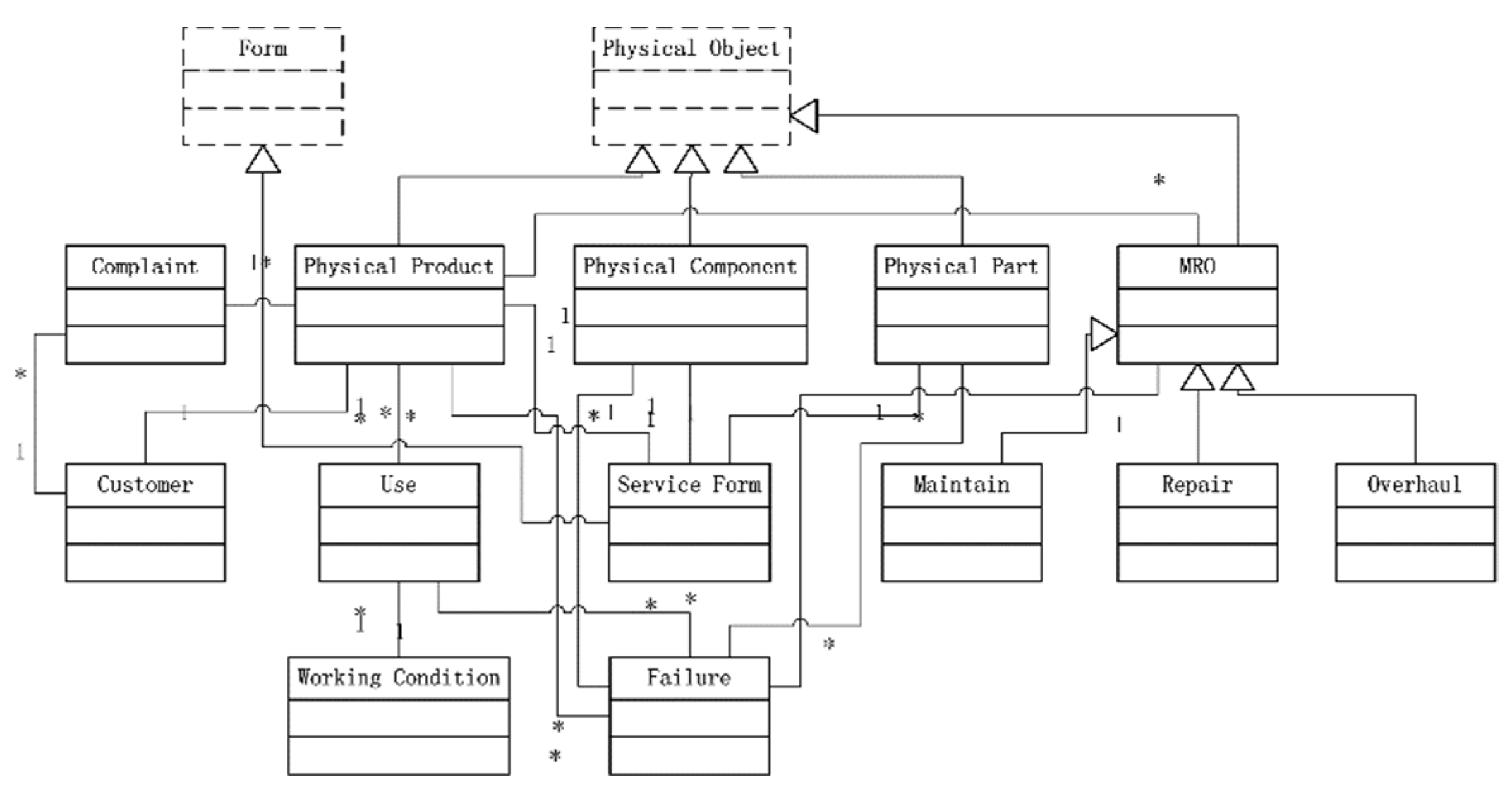
Service contains the use, maintenance, repair, and overhaul. The data contain the working condition, failure, maintenance, repair, overhaul, and complaint. Based on PCDM, SPrDM is built, as shown in Figure 9. The Physical Product is owned by a Customer, who has Gripe, and has many uase data, which involved Working Condition and brings Failure. It has MRO, including Maintain, Repair and Overhaul. MRO addresses the Failure of Physical Product, Physical Component and Physical Part. Physical Product, Physical Component and Physical Part have Service Form managing their attributes in the Service phase.
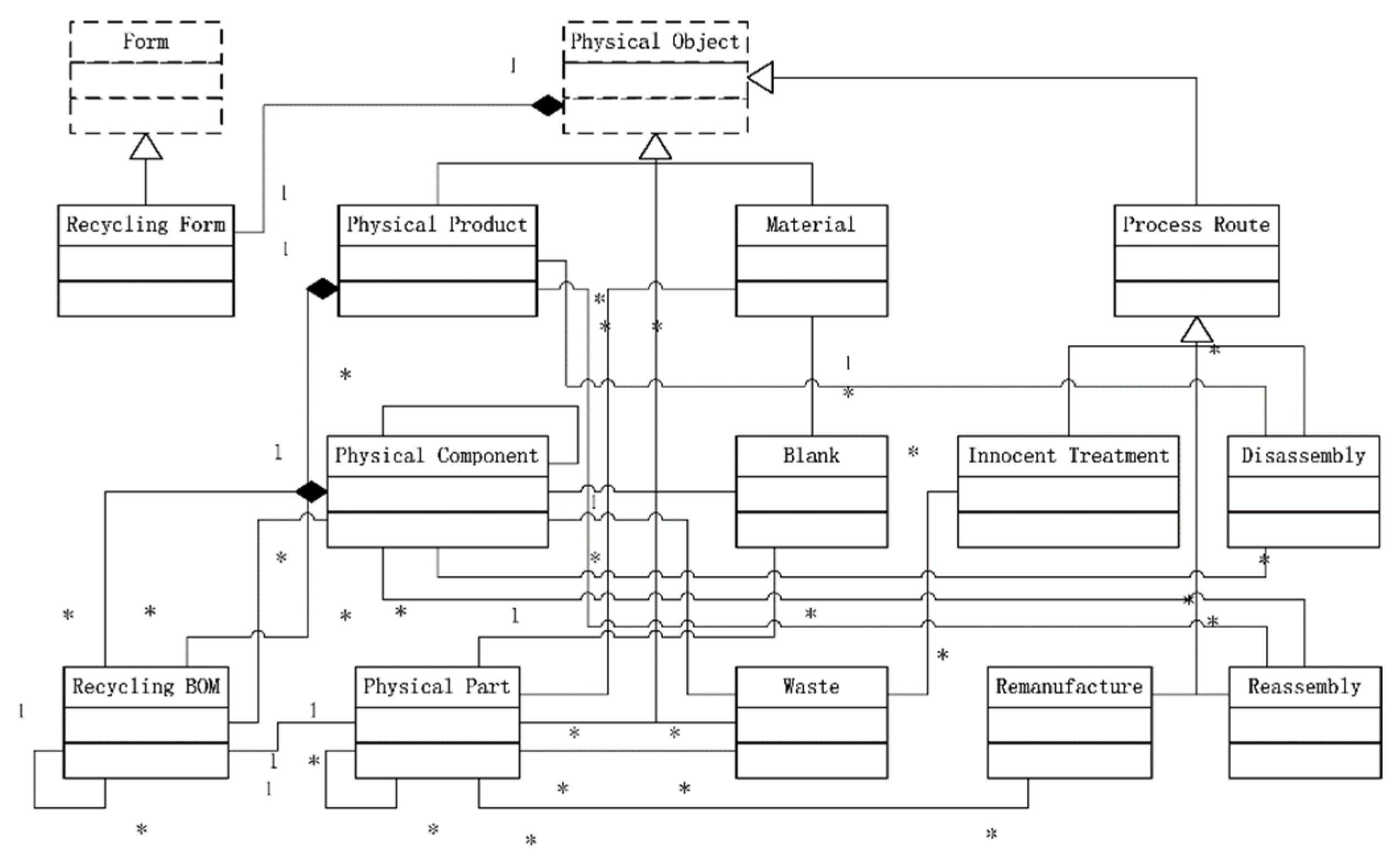
Recycling contains disassembly, cleanout, detection, reuse, remanufacturing, regeneration, burning, and Landfill. When out of service, physical products are taken to circulation economy enterprises. Physical products and components are disassembled, and the physical parts are cleaned. After detection, some are reused directly in other products, and others are remanufactured to recover the performance, regenerated for the material then burned and landfilled. Based on PCDM, RPrDM is built, as shown in Figure 10. Physical Product and Physical Component are dismantled, and we obtain Physical Component, Physical Part, Material and Waste. Some can be reused. Blank, which is machined to a new Physical Part, comes from Material. Waste receives Innocent Treatment. A new Physical Product is presented by Remanufacture and Reassembly of Physical Component and Physical Part. All Physical Objects in the recycling phase have a Recycling Form for their recycling attributes. The content and management of the Process Route are the same as that for the Process Phase.
5.3. Document Management
Document management is the basic function of PLM and is the first requirement of customers. It manages unstructured data, including two-dimensional drawings, three-dimensional models, calculations, specifications, and simulation analysis data. Unstructured data are transferred and stored as a whole one, not considering the logic and stored structure.
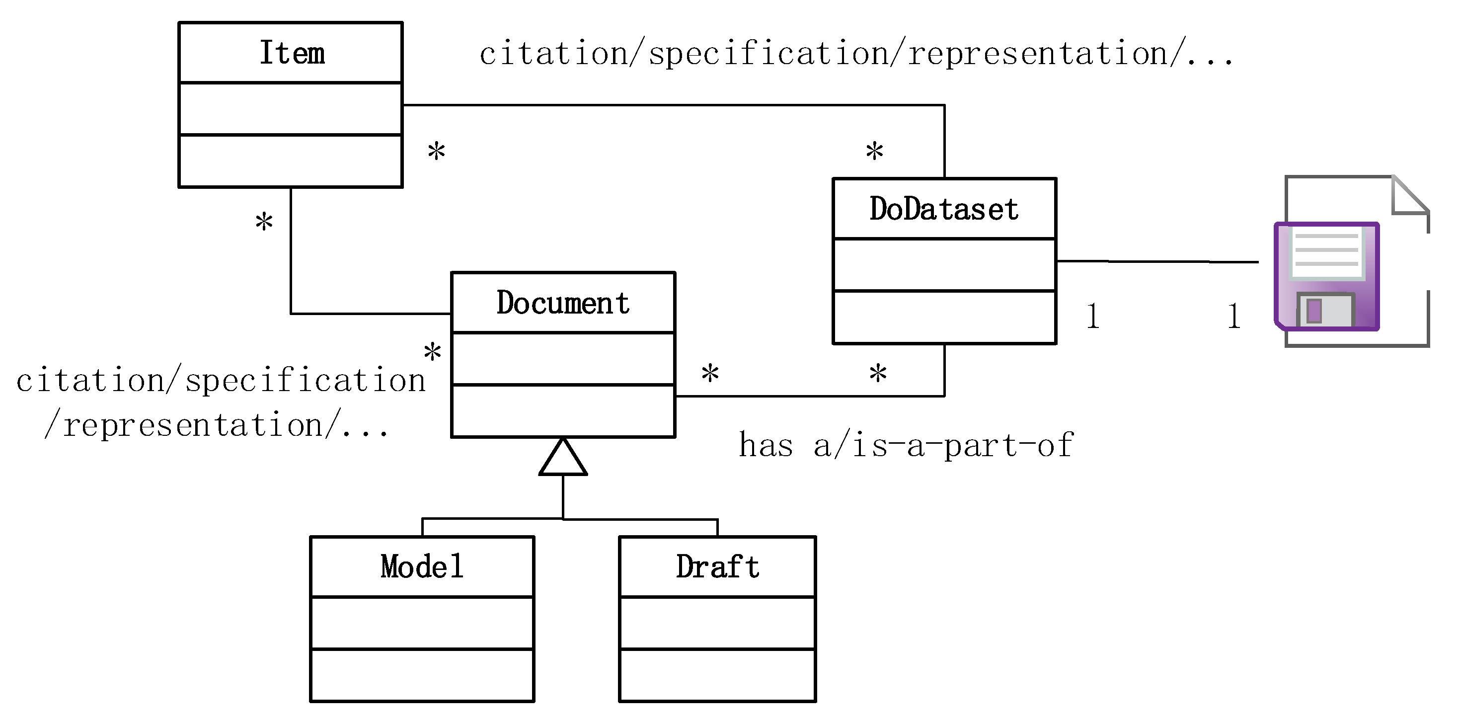
Document management uses meta-data to manage all of the types of documents, as shown in Figure 11. DoDataset is meta-data to manage the file. Item is related to Document and DoDataset by citation, specification, and representation. Document, which is a superclass of Model and Draft, organises DoDataset of several files for the logic file, for example, a manual is composed of files in Chinese and in English, Model contains UG NX files and CATIA files, and Draft includes a metric drawing and an imperial drawing of the same content.
6. Case Study
An example using UDMPM to manage data on shipping in Huanghai Shipbuilding Co. Ltd. is studied. A sship is a complex product system, involving several majors. There are complex relations among phases, system, sections, components, parts and documents. The ship’s data management has obvious characteristics, and a unified data model for a conceptual ship, digital ship and physical ship is built. Because the ship has too much data, the case focuses on the marine engine system.
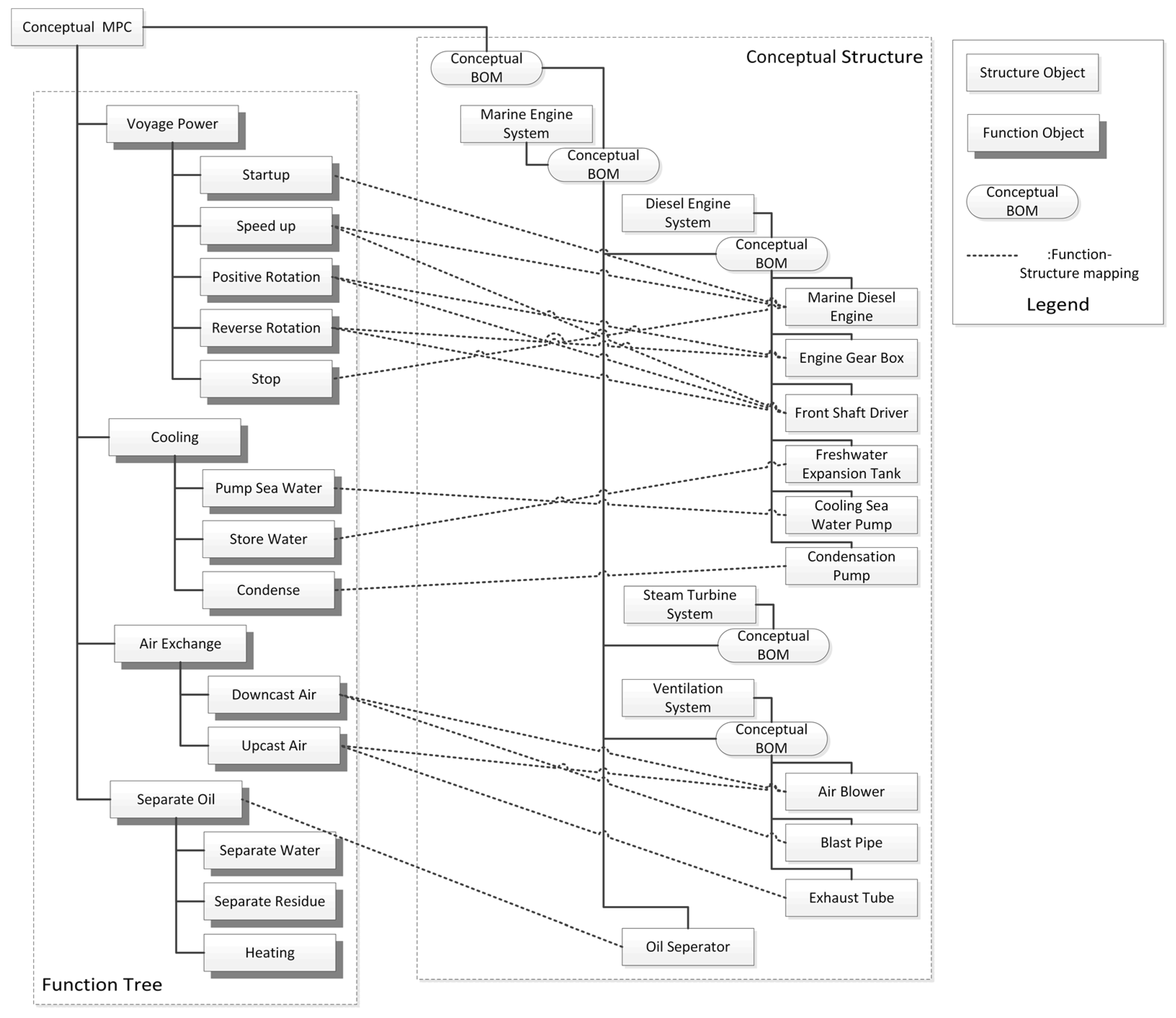
In a shipyard, a conceptual ship manages a ship type, such as a Multi-Purpose Container (MPC) Vessel, a Ro-Ro Passenger Vessel, or an Oil Tanker. MPC is a type of ship to transfer containers, and its CCDM is shown in Figure 12. Conceptual MPC uses a function tree and a conceptual structure to manage all the conceptual data. The function of a marine engine system includes voyage power, cooling, air exchange and separate oil. The Marine Engine System has a Diesel Engine System, a Steam Turbine System, a Ventilation System and an Oil Separator. Diesel Engine Systems and Steam Turbine Systems both achieve voyage power and are redundant units. However, a conceptual MPC can select one or two types. Function–Structure mapping describes the relation between the function and structure units.
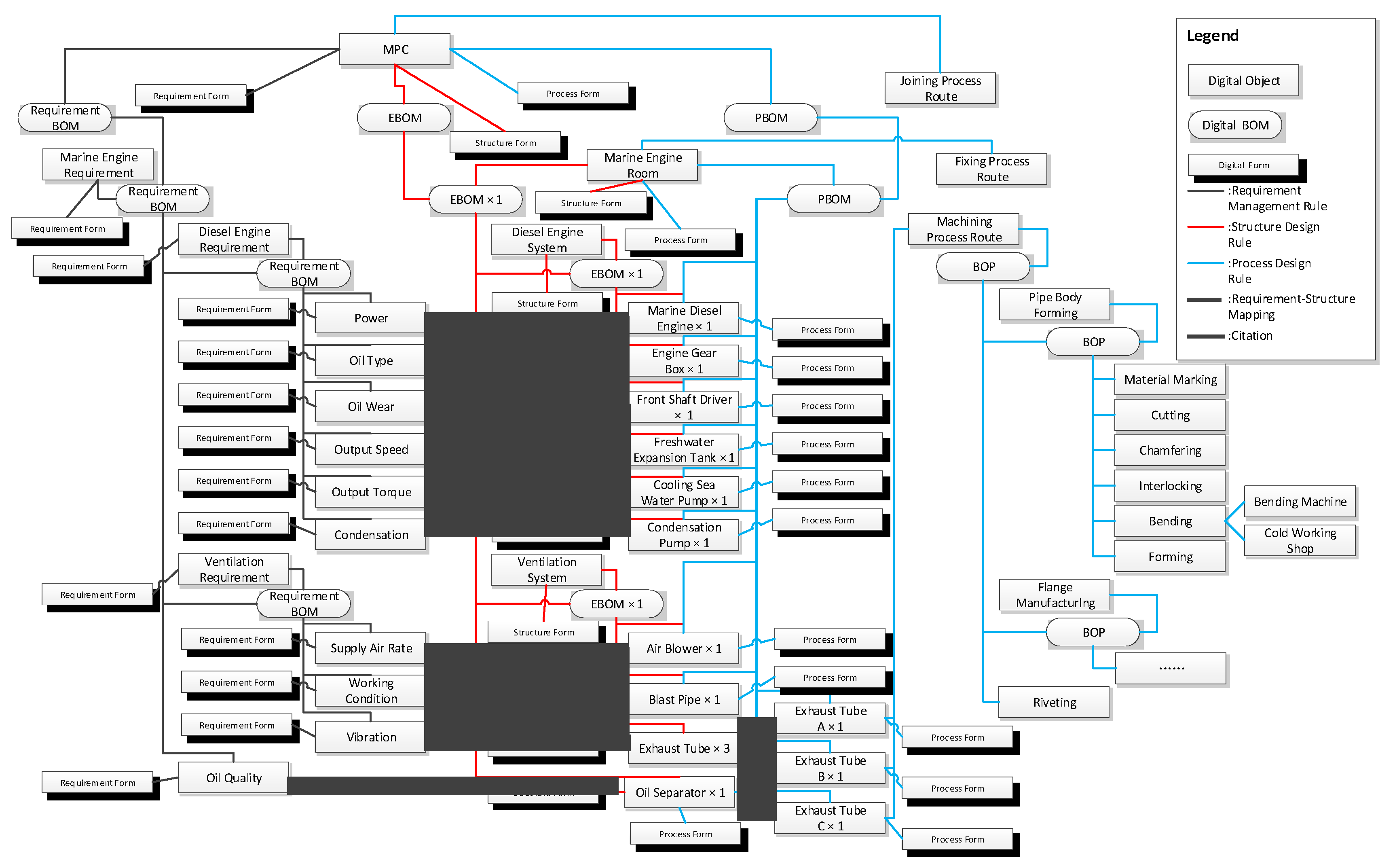
Digital MPC originates from conceptual MPC and manufactures one or several physical MPCs. The DCDM of digital MPC is shown in Figure 13. Some digital objects can cover several business phases for uniqueness, such as the digital MPC existing in the requirements management phase, the structure design phase and the process design phase. Thus, digital MPC has Requirement Form, Structure Form and Process Form, which separately contain the attributes of corresponding phases. Requirement Form owns attributes, such as the seaworthy area, dead weight ton and seating capacity. Structure Form includes the length, width, height, and draught. The Process Form has a section number, max section weight, and welding requirements. Digital MPC uses Requirement BOM, Structure BOM and Process BOM to construct the backbone of the data. The black line, red line and green line separately express the Requirement Management Rule of RRF, the Structure Design Rule of SRF and the Process Design Rule of PRF, and RPDM, SPDM and PrPDM. In SPDM, sub-Items of the Marine Engine Room are the Diesel Engine System and the Ventilation System, which disappear in PrPDM because they are virtual parts, and they appear only for planning processes of structure design management. The long broken line is Requirement–Structure Mapping. The short dotted line is the Citation between design parts. The Exhaust Tube has a single structure, and Exhaust Tube A, B and C have different installation sites. They separately represent structure information and process information on the same part. Digital MPC, Marine Engine Room and Exhaust Tube separately own Joining Process Route, Fixing Process Route and Machining Process Route. The Machining Process Route is shown in Figure 13, and others are omitted. The bending process step uses the Bending Machine in the Cold Working Shop.
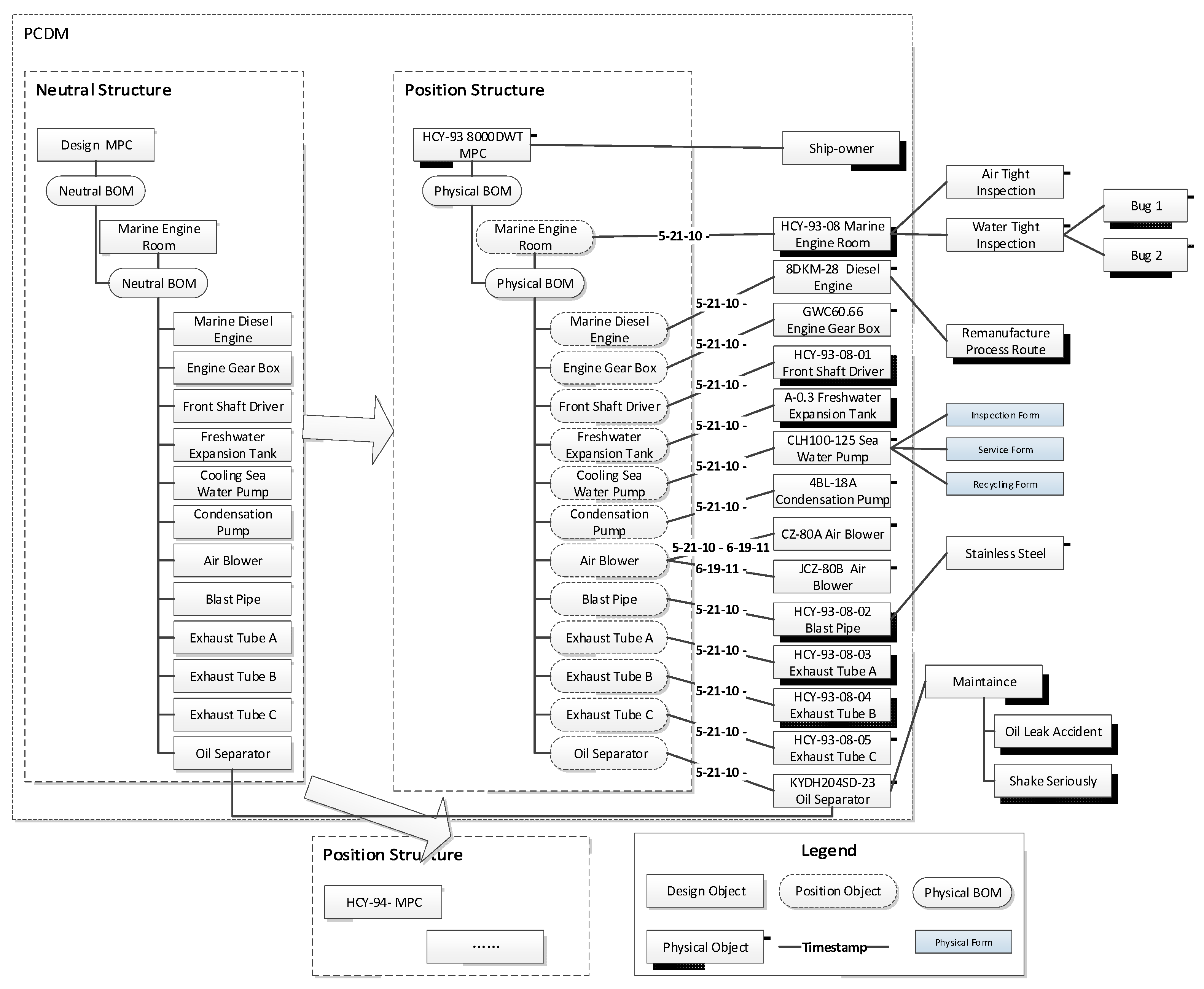
Every physical MPC has a unique ID, such as HCY-93, which has 8000 Dead Weight Ton (DWT), as shown in Figure 14. In PCDM, Neutral Structure is a mirror of PBOM, and the object comes from PBOM, also. The Position Structures of HCY-93 and HCY-94 are copies of Neutral Structure, using position objects. Timestamp manages the installation relation of position objects and physical objects. Before 6/19/11, the Air Blower uses CZ-80A, and after 6/19/11, it uses JCZ-50B. All of the physical objects are produced according to their corresponding design objects and obtain design attributes from them, such as the design performance and working condition, for example, the KYDH204SD-23 Oil Separator. The CLH100-125 Sea Water Pump has Inspection Form for inspection information, Service Form for use and MRO information and Recycling Form for disposal and recycling information. In the Inspection phase, HCY-93-08 Marine Engine Room experiences Air Tight Inspection and Water Tight Inspection, in which two bugs are found. In service, the KYDH204SD-23 Oil Separator is maintained, because of failures tracked by the system such as Oil Leak Accident and Shake Seriously. In recycling, 8DKM-28 Diesel Engine has Remanufacture Process Route to recover performance, and Stainless Steel is obtained from the HCY-93-08-02 Blast Pipe.
7. Discussion
There are three forms in the product life cycle: conceptual products, digital products and physical products. The carrier and data evolution characteristics of these three product forms are different, so it is difficult to efficiently integrate product life cycle data.
In the product life cycle, there are several business stages such as conceptual design, structural design, process design, manufacturing, and service use. Many previous studies established a data model or BOM for each stage, and integrated them using mapping. Other studies established a model for all stages as the only data source. The former abandons the common characteristics of data in multiple stages of a product form and weakens the evolutionary relationship between them. The latter cannot manage the data of each product form according to its characteristics and distinguishes the evolution mode of each product form.
The paper summarizes the connotation of the three forms of products, and proposes a unified product data management model that covers the differences in data management among three product forms. Based on previous researches, the data model is constructed at two levels: product form and business stage. We have inherited the business-oriented modeling method and the idea of a single data source, and combined the two organically.
8. Conclusions
In this paper, we present a data management approach that is based on three product morphology types for concept data, digital data and physical data over the course of a full lifecycle. Three product morphology types and UDMPM are the core of the approach. Product morphology is classified into three types: conceptual product, digital product and physical product, by the carrier and the evolutionary characteristics of the product. According to the evolutionary characteristics of every product morphology type, UDMPM makes a corresponding management mode. A conceptual product has one business phase, and a single data model, and CCDM is the best approach. Because designing a product involves requirements management, structure design and process design, and because it evolves continually, a flexible DCDM allows for consistency and integrality. In addition, business applications are supported by phase data models, which are founded by adding phase rule filters on the DCDM. The structure and features of a physical product are not changeless, but properties and status change over time. Then, PCDM manages changeless data, and the phase private data model describes the changed data. In general, the approach integrates three data management modes into a whole system, which addresses all of the data in the full lifecycle, eliminating data redundancy and holding consistency and integrality.
Previous research focused on the integration of multi-stage BOM or data model with data mapping, or a single data source of multiple stages. Based on the above research, the paper summarizes the three forms of product connotation and proposes a unified product data management model, establishing a single data source for each product form, manage multiple stages of data and the data evolution between them, using global object mapping to integrate three data models, and providing a new method for integrated management of product life cycle data.
In the current research, big product data are of great significance to product operation and maintenance and design and manufacturing. Digital twin technology is also a current research hotspot. The data characteristics of big data are different from the data studied in this article. Digital twins are another carrier of products, and their evolutionary characteristics are also different from the data studied in this article. Due to limited conditions, the paper did not study the management model of big data and digital twins. This is an area for future research.
Author Contributions
Conceptualization, Y.W.; Data curation, R.M.; Formal analysis, G.L.; Funding acquisition, Y.W.; Investigation, R.M.; Methodology, G.L.; Project administration, G.L.; Resources, G.L.; Supervision, G.L.; Validation, R.M.; Writing—original draft, Y.W.; Writing—review and editing, R.M. All authors have read and agreed to the published version of the manuscript.
Funding
This research was funded by the National Key Research and Development Program of China, grant number 2018YFB1702601, the Major Scientific and Technological Innovation Projects in Shandong Province, grant number 2019JZZY010442 and Natural Science Foundation of Shandong Province, grant number ZR2020MF085.
Acknowledgments
We thank managers and engineers of Shandong Hoteam Software Co. Ltd. and Huanghai Shipbuilding Co. Ltd. for their kind help.
Conflicts of Interest
The authors declare no conflict of interest.
References
- Gecevska, V.; Chiabert, P.; Anisic, Z.; Lombard, F.; Cus, F. Product lifecycle management through innovative and competitive business environment. J. Ind. Eng. Manag. 2010, 3, 323–336. [Google Scholar] [CrossRef]
- Sudarsan, R.; Fenves, S.J.; Sriram, R.D.; Wang, F. A product information modeling framework for product lifecycle management. Comput. Aided Des. 2005, 37, 1399–1411. [Google Scholar] [CrossRef]
- Li, Y.; Wan, L.; Xiong, T. Product data model for PLM system. Int. J. Adv. Manuf. Technol. 2011, 55, 1149–1158. [Google Scholar] [CrossRef]
- Zihang, X.; Jiping, Y.; Sheng, Y.; Tao, H. Research on Product Lifecycle Model-Based on UML. IOP Conf. Ser. 2021, 632, 052078. [Google Scholar]
- Kreis, A.; Hirz, M.; Stadler, S.; Salchner, M.; Rossbacher, P. Convenient connection technology data model supporting optimized information exchange between CAx-systems. Comput. Aided Des. Appl. 2018, 15, 771–778. [Google Scholar] [CrossRef]
- Tao, J.; Yu, S. A Meta-model based Approach for LCA-oriented Product Data Management. Procedia CIRP 2018, 69, 423–428. [Google Scholar] [CrossRef]
- Dhamija, D.; Koonce, D.A.; Judd, R.P. Development of a unified data meta-model for CAD-CAPP-MRP-NC verification integration. Comput. Ind. Eng. 1997, 33, 19–22. [Google Scholar] [CrossRef]
- Studer, R.; Benjamins, V.R.; Fensel, D. Knowledge engineering: Principles and methods. Data Knowl. Eng. 1998, 25, 161–197. [Google Scholar] [CrossRef] [Green Version]
- Sanfilippo, E.M. Feature-based product modelling: An ontological approach. Int. J. Comput. Integr. Manuf. 2018, 31, 1097–1110. [Google Scholar] [CrossRef]
- Ebrahimipour, V.; Rezaie, K.; Shokravi, S. An ontology approach to support FMEA studies. Expert Syst. Appl. 2010, 37, 671–677. [Google Scholar] [CrossRef]
- Gim, D.M.; Vegetti, M.; Leone, H.P.; Henning, G.P. PRoduct ONTOlogy: Defining product-related concepts for logistics planning activities. Comput. Ind. Prod. Lifecycle Model. Anal. Manag. 2008, 59, 231–241. [Google Scholar]
- Lu, Y.; Wang, H.; Xu, X. ManuService ontology: A product data model for service-oriented business interactions in a cloud manufacturing environment. J. Intell. Manuf. 2019, 30, 317–334. [Google Scholar] [CrossRef]
- Dori, D.; Shpitalni, M. Mapping Knowledge about Product Lifecycle Engineering for Ontology Construction via Object-Process Methodology. CIRP Ann. Manuf. Technol. 2005, 54, 117–122. [Google Scholar] [CrossRef]
- Choi, S.S.; Yoon, T.H.; Noh, S.D. XML-based neutral file and PLM integrator for PPR information exchange between heterogeneous PLM systems. Int. J. Comput. Integr. Manuf. 2010, 23, 216–228. [Google Scholar] [CrossRef]
- Hu, X.; Xu, Y. Research on semi-structured and unstructured data storage and management model for multi-tenant. J. Inf. Technol. Res. 2019, 12, 49–62. [Google Scholar] [CrossRef]
- Zhang, Y.; Zhang, C.; Wang, H. An Internet based STEP data exchange framework for virtual enterprises. Comput. Ind. 2000, 41, 51–63. [Google Scholar] [CrossRef]
- Mehli-Qaissi, J.; Coulibaly, A.; Mutel, B. Product data model for production management and logistics. Comput. Ind. Eng. 1999, 37, 27–30. [Google Scholar] [CrossRef]
- Behera, A.K.; McKay, A.; Earl, C.F.; Chau, H.H.; Robinson, M.A.; de Pennington, A.; Hogg, D.C. Sharing design definitions across product life cycles. Res. Eng. Des. 2019, 30, 339–361. [Google Scholar] [CrossRef] [Green Version]
- Eynard, B.; Gallet, T.; Roucoules, L.; Ducellier, G. PDM system implementation based on UML. Math. Comput. Simul. Comput. Eng. Syst. Appl. 2006, 70, 330–342. [Google Scholar] [CrossRef]
- Albert, A.; Jonas, H.; Benjamin, W.; Gustav, N.B.; Nicolas, R.; Nicolas, H.; Sascha, O.; Nikola, B. Product Profiles: Modelling customer benefits as a foundation to bring inventions to innovations. Procedia CIRP 2018, 70, 253–258. [Google Scholar] [CrossRef]
- Zhou, C.; Cao, Q. Design and implementation of intelligent manufacturing project management system based on bill of material. Clust. Comput. 2019, 22, 8647–8655. [Google Scholar] [CrossRef]
- McKay, A.; Chau, H.H.; Earl, C.F.; Behera, A.K.; de Pennington, A.; Hogg, D.C. A lattice-based approach for navigating design configuration spaces. Adv. Eng. Inform. 2019, 42, 100928. [Google Scholar] [CrossRef] [Green Version]
- Shuyu, C.; Die, H.; Yang, F.; Jianxin, X. Research on BOM multi-view mapping method orient to aircraft in-service data management. J. Phys. Conf. Ser. 2020, 1550, 032124. [Google Scholar]
- Jing, F.; Yang, W.; Zhang, Y.; Zhou, R.; Gao, X. Dynamic BOM Construction Technology and Application Based on MBD. J. Phys. Conf. Ser. 2020, 1486, 072050. [Google Scholar]
- Li, H.; Ji, Y.; Luo, G.; Mi, S. A modular structure data modeling method for generalized products. Int. J. Adv. Manuf. Technol. 2016, 84, 197–212. [Google Scholar] [CrossRef]
- Wu, W.; Fan, X.; Zhou, G.; Huang, Y.; Cao, Y.; Lin, G. A Material Recommendation System for Enterprise Manufacturing Integrated Systems. Zhongguo Jixie Gongcheng/China Mech. Eng. 2019, 30, 1856–1865. [Google Scholar]
- Xia, L.; Ri, N.J.; Han, T.Z. Product parameter calculation based on configurable BOM model. J. Phys. Conf. Ser. 2020, 1486, 032036. [Google Scholar]
Figure 1.
UDMPM Framework.

Figure 2.
Static Classes Structure of Product Lifecycle Objects (1, * represent the one and multi-object).
Figure 2.
Static Classes Structure of Product Lifecycle Objects (1, * represent the one and multi-object).

Figure 3.
CPhDM (1, * represent the one and multi-object).

Figure 4.
DPDM.

Figure 5.
Digital Core Data Model (1, * represent the one and multi-object).

Figure 6.
PPDM.

Figure 7.
Physical Core Data Model (1, * represent the one and multi-object).

Figure 8.
Inspection Private Data Model (1, * represent the one and multi-object).

Figure 9.
Service Private Data Model (1, * represent the one and multi-object).

Figure 10.
Recycling Private Data Model (1, * represent the one and multi-object).

Figure 11.
Document Management Data Model (1, * represent the one and multi-object).

Figure 12.
Conceptual Ship—Multi Purpose Container vessel.

Figure 13.
Digital Ship—Multi Purpose Container vessel.

Figure 14.
Physical Ship—Multi Purpose Container vessel.


Table 1.
Attributes of conceptual object.
| Object | Attribute |
|---|---|
| Conceptual Product | Usage, performance, function, unit, description, mender, modification time |
| Conceptual Component | Specification, performance, description, mender, modification time |
| Conceptual Part | Specification, performance, description, mender, modification time |
| Function | Content, description, mender, modification time |
Table 2.
Attributes of digital object.
| Object | Attribute |
|---|---|
| Digital Product | Model, weight, material, design organisation, mender, modification time |
| Digital Component | Weight, material, mender, modification time |
| Digital Part | Weight, material, mender, modification time |
| Process Route | Process type, station, time, description |
| Working Procedure | Type, description |
| Process Step | Type, description |
| Requirement | Content, description |
| Resource | Resource type, working condition, usage state |
Table 3.
Attributes of a physical object.
| Object | Attribute |
|---|---|
| Physical Product | Serial number, batch number, manufacturer, production time, producing area, quality controller, performance, working condition, weight, length, width, height, and other attributes. |
| Physical Component | Serial number, batch number, producer, production time, producing area, quality controller, weight, length, width, height, material, resource (self-manufacturing, procurement, buy) |
| Physical Part | Serial number, batch number, producer, production time, producing area, quality controller, weight, length, width, height, material, origin (self-manufacturing, procurement, buy) |
| Inspection | Inspection type, object, time, place, checker, degree, content, result, standard, tool |
| Maintenance | Object, failures, state (closed, delay, fixed, new, open, rejected, reopen), maintainer, begin time, finish time, place, description |
Table 4.
Attributes of rules (1, * represent the one and multi-object).
| Attribute | Signification | Option |
|---|---|---|
| ID | Identify each rule | Number or string |
| Name | Name of the rule | String |
| Phase | Phase of the rule | Requirements Management, Structure Design, Process Design or Production |
| Priority | Right to proceed before another | Number |
| Relation | Relationship between Source Object and Destination Object | Has-a/is-a-part-of, Specification, Compose, Reference or Requirement |
| Source Object | The first object of the rule | All types of business objects or data objects |
| Destination Object | The second object of the rule | |
| Multiplicity | Number of Source Object and Destination Object in the rule | 1/*/0..1/0..*/1..* |
| Access | Access to operate the rule |
Table 5.
Set of rules in the requirements management phase (1, * represent the one and multi-object).
Table 5.
Set of rules in the requirements management phase (1, * represent the one and multi-object).
| Relation | Source Object | Destination Object | Multiplicity |
|---|---|---|---|
| Inherit | Design Object | Requirement | |
| Inherit | Design Object | Design Product | |
| Inherit | Form | Requirement Form | |
| Inherit | Phase | Requirement Management Phase | |
| Inherit | Design BOM | Requirement BOM | |
| Has-a/is-a-part-of | Design Product | Requirement BOM | 1:1 |
| Has-a/is-a-part-of | Requirement | Requirement BOM | 1:0..1 |
| Has-a/is-a-part-of | Requirement | Requirement Form | 1:1 |
| Has-a/is-a-part-of | Requirement BOM | Requirement | 1:* |
| Has-a/is-a-part-of | Requirement Management Phase | Requirement BOM | 1:* |
| Has-a/is-a-part-of | Requirement Management Phase | Requirement Form | 1:* |
| Has-a/is-a-part-of | Requirement Management Phase | Requirement | 1:* |
| Has-a/is-a-part-of | Requirement Management Phase | Design Product | 1:* |
| Requirement/Function | Requirement | Design Object | *:* |
| Has-a/is-a-part-of | Design Product | Requirement Form | 1:1 |
| Has-a/is-a-part-of | Phase | Design Object | *:* |
| Inherit | Requirement | Customer Requirement | |
| Inherit | Requirement | Usage Requirement | |
| Inherit | Requirement | Sales Requirement | |
| Inherit | Requirement | Management Requirement | |
| Inherit | Requirement | Technology Requirement |
Table 6.
Set of rules in the design phase (1, * represent the one and multi-object).
| Relation | Source Object | Destination Object | Multiplicity |
|---|---|---|---|
| Inherit | Design Object | Design Product | |
| Inherit | Design Object | Design Component | |
| Inherit | Design Object | Design Part | |
| Inherit | Form | Structure Form | |
| Inherit | Phase | Structure Design Phase | |
| Inherit | Design BOM | EBOM | |
| Has-a/is-a-part-of | Design Product | EBOM | 1:1 |
| Has-a/is-a-part-of | Design Component | EBOM | 1:1 |
| Has-a/is-a-part-of | EBOM | EBOM | 1:* |
| Has-a/is-a-part-of | EBOM | Design Part | 1:* |
| Has-a/is-a-part-of | Design Product | Structure Form | 1:1 |
| Has-a/is-a-part-of | Design Component | Structure Form | 1:1 |
| Has-a/is-a-part-of | Design Part | Structure Form | 1:1 |
| Specification, Compose, Reference, Requirement | Design Object | Design Object | *:* |
| Has-a/is-a-part-of | Structure Design Phase | Design Product | 1:* |
| Has-a/is-a-part-of | Structure Design Phase | Design Component | *:* |
| Has-a/is-a-part-of | Structure Design Phase | Design Part | *:* |
| Has-a/is-a-part-of | Structure Design Phase | EBOM | 1:* |
| Has-a/is-a-part-of | Structure Design Phase | Structure Form | 1:* |
| Requirement/Function | Requirement | Design Object | *:* |
Table 7.
The set of rules in the process phase (1, * represent the one and multi-object).
| Relation | Source Object | Destination Object | Multiplicity |
|---|---|---|---|
| Inherit | Design Object | Design Product | |
| Inherit | Design Object | Design Component | |
| Inherit | Design Object | Design Part | |
| Inherit | Design Object | Process Route | |
| Inherit | Design Object | Working Procedure | |
| Inherit | Design Object | Process Step | |
| Inherit | Design Object | Resource | |
| Inherit | Design Object | Work Area | |
| Inherit | Process Route | Assembly Process | |
| Inherit | Process Route | Manufacturing Process | |
| Inherit | Form | Process Form | |
| Inherit | Phase | Process Phase | |
| Inherit | Design BOM | PBOM | |
| Inherit | Design BOM | BOP | |
| Inherit | Design BOM | BOR | |
| Inherit | Design BOM | BOWA | |
| Has-a/is-a-part-of | Design Product | PBOM | 1:1 |
| Has-a/is-a-part-of | PBOM | PBOM | 1:* |
| Has-a/is-a-part-of | Design Component | PBOM | 1:1 |
| Has-a/is-a-part-of | PBOM | Design Part | 1:* |
| Has-a/is-a-part-of | Process Phase | PBOM | 1:* |
| Has-a/is-a-part-of | Design Product | Process Form | 1:1 |
| Has-a/is-a-part-of | Design Component | Process Form | 1:1 |
| Has-a/is-a-part-of | Design Part | Process Form | 1:1 |
| Has-a/is-a-part-of | Process Phase | Process Form | 1:* |
| Has-a/is-a-part-of | Process Phase | Design Product | 1:* |
| Has-a/is-a-part-of | Process Phase | Design Component | *:* |
| Has-a/is-a-part-of | Process Phase | Design Part | *:* |
| Has-a/is-a-part-of | Process Phase | Process Route | *:* |
| Has-a/is-a-part-of | Process Phase | Working Procedure | *:* |
| Has-a/is-a-part-of | Process Phase | Process Step | *:* |
| Has-a/is-a-part-of | Process Phase | Resource | *:* |
| Has-a/is-a-part-of | Process Phase | Work Area | *:* |
| Has-a/is-a-part-of | Process Phase | Assembly Process | *:* |
| Has-a/is-a-part-of | Process Phase | Manufacturing Process | *:* |
| Has-a/is-a-part-of | Process Phase | BOP | *:* |
| Has-a/is-a-part-of | Process Phase | BOR | *:* |
| Has-a/is-a-part-of | Process Phase | BOWA | *:* |
| Design/Assembly | Design Product | Assembly Process | *:* |
| Design/Assembly | Design Component | Assembly Process | *:* |
| Design/Manufacture | Design Part | Manufacturing Process | *:* |
| Has-a/is-a-part-of | Design Process | BOP | 1:1 |
| Process/Resource | Design Process | Resource | *:* |
| Process/Work Area | Design Process | Work Area | *:* |
| Has-a/is-a-part-of | BOP | BOP | 1:* |
| Has-a/is-a-part-of | Working Procedure | BOP | 1:1 |
| Process/Resource | Working Procedure | Resource | *:* |
| Process/Work Area | Working Procedure | Work Area | *:* |
| Has-a/is-a-part-of | BOP | Process Step | 1:* |
| Process/Resource | Process Step | Resource | *:* |
| Process/Work Area | Process Step | Work Area | *:* |
| Has-a/is-a-part-of | Resource | BOR | 1:1 |
| Has-a/is-a-part-of | BOR | BOR | 1:* |
| Has-a/is-a-part-of | BOR | Resource | *:* |
| Has-a/is-a-part-of | Work Area | BOWA | 1:1 |
| Has-a/is-a-part-of | BOWA | BOWA | 1:* |
| Has-a/is-a-part-of | BOWA | Work Area | *:* |
Publisher’s Note: MDPI stays neutral with regard to jurisdictional claims in published maps and institutional affiliations. |
© 2021 by the authors. Licensee MDPI, Basel, Switzerland. This article is an open access article distributed under the terms and conditions of the Creative Commons Attribution (CC BY) license (https://creativecommons.org/licenses/by/4.0/).
Share and Cite
MDPI and ACS Style
Liu, G.; Man, R.; Wang, Y. A Data Management Approach Based on Product Morphology in Product Lifecycle Management. Processes 2021, 9, 1235. https://0-doi-org.brum.beds.ac.uk/10.3390/pr9071235
AMA Style
Liu G, Man R, Wang Y. A Data Management Approach Based on Product Morphology in Product Lifecycle Management. Processes. 2021; 9(7):1235. https://0-doi-org.brum.beds.ac.uk/10.3390/pr9071235
Chicago/Turabian StyleLiu, Gang, Rongjun Man, and Yanyan Wang. 2021. "A Data Management Approach Based on Product Morphology in Product Lifecycle Management" Processes 9, no. 7: 1235. https://0-doi-org.brum.beds.ac.uk/10.3390/pr9071235
Note that from the first issue of 2016, this journal uses article numbers instead of page numbers. See further details here.