
A Novel Centrifugal Filtration Device


1
Department of Chemical and Materials Engineering, Tamkang University, 151 Ying-chuan Road, Tamsui, Taipei County 25137, Taiwan
2
Department of Environmental and Safety Engineering, Ming Chi University of Technology, Taishan, New Taipei City 24301, Taiwan
*
Author to whom correspondence should be addressed.
Separations 2022, 9(5), 129; https://0-doi-org.brum.beds.ac.uk/10.3390/separations9050129
Submission received: 16 April 2022
/
Revised: 20 May 2022
/
Accepted: 20 May 2022
/
Published: 21 May 2022
(This article belongs to the Special Issue Research on Separation Performance of Separator)
Abstract
:In the proposed centrifugal filtration device, a filter is mounted in the center of the centrifugal chamber. The particles move towards the centrifuge wall away from the filter under centrifugal force, so a filtration cake is unlikely to accumulate here. The working fluid is injected continuously, so the feed pressure is higher than the discharge pressure, which compels the light-phase fluid to leave through the filter as filtrate. The filtrate flux rate and the movement of particles in the centrifugal chamber of the proposed filtration device were investigated using different powder particle sizes, concentrations of working fluid, centrifugal chamber rotation speeds, and filters. With a higher centrifugal chamber rotation speed, the centrifugal force acting on the particles in the centrifugal chamber was stronger, and the particles were less likely to adhere to the central filter; hence, a larger amount of filtrate was produced.
1. Introduction
Filtration technology is a well-established method of solid-liquid separation [1,2,3] that is used in various fields, such as water/wastewater treatment [4,5] and oil separation [6].
Centrifugal force is often used for industrial solid–liquid separation [7,8], because it generates a powerful filtration driving force that separates solid and liquid phases rapidly. Centrifugation has been implemented for separating substances in industrial and laboratory settings for a long time, ever since it was first used for milk separation in farms [9]. Currently, centrifugal separation is usually applied in biomedical technology. Fukuyama et al. discussed the consolidation behavior of centrifugal dewatering with and without a supernatant [10]. Li et al. recovered linseed oil from a water emulsion using rotating-disk filtration and produced good results [11]. Jaffrin comprehensively compared and reviewed rotating disks, rotating membranes, and vibrating systems [12].
Centrifugal filtration equipment is characterized by a high processing capacity and small size [13]. Compared with other separators, the centrifuge not only produces a solid with a low water content and a high-purity supernatant, but it is also highly leak-proof. It can work continuously and can be extensively used in the refinement of petrochemicals; sludge thickening and the dewatering of sewage in treatment plants; the extraction of pesticides and biopharmaceuticals; and the medical, food, textile, metallurgical, and environmental protection industries.
The ratio of centrifugal acceleration to gravitational acceleration generated in the operation of a centrifuge is known as the separation factor (Fr), and it is expressed as follows:
where r is the radius of rotation, ω is the rotation speed, and g is the gravitational acceleration.
The larger the separation factor (Fr), the larger the centrifugal force on the particles and the more effective the separation. A centrifuge with a large separation factor must be used for materials with a high solution viscosity and fine particles. At present, the centrifuge separation factor (Fr) values for industrial use range from being in the hundreds to being in the hundreds of thousands. In this work, the largest Fr value was about 44,700.
The methods that use high rotation speeds to generate centrifugal force for solid–liquid separation are dynamic filtration and high-shear-force crossflow filtration, which generates a high shear force on the membrane surface to produce relative motion between the membrane and casing [14]. Two pieces of commercial equipment with different structures can be used for this process: a cylindrical Couette device [15,16] and a rotating disk [17]. The former uses the relatively high-speed rotation of two coaxial cylinders to generate high shear stress, and the inner cylinder is a membrane. The latter is a disk rotating at a high speed between two circular membranes. Four mechanisms can be implemented in rotating cylindrical filtration to mitigate the fouling on the membrane surface, resulting in a high filtration rate [18]: (1) annular Poiseuille flow between two cylinders, generating in axial shear stress; (2) circular Couette flow from the high-speed rotation of two coaxial cylinders, generating rotational shear stress; (3) high-speed rotation, generating a strong centrifugal force field; and (4) secondary vortex flow, causing the elutriation of particles on the filter surface.
In the fluid rotary system, a particle receives two radial acting forces: centrifugal force, which makes the particles move outwards, and Stokes drag. Therefore, in the case of force equilibrium,
where and are the density of the particles and fluid, respectively; is the particle size; and and are the radial velocity of the particles and fluid in position r, respectively. Equation (2) assumes that the flow pattern is not turbulent. Therefore,
Equation (3) represents the radial velocity of particles on the membrane surface (position ri). The particle Taylor number is the bracketed term [18]; ri and Ω are the radius and rotational speed of the inner cylinder, respectively; and μ is the fluid viscosity.
Wereley et al. [19] used a porous polyethylene cylindrical filter with a nominal pore size of 5 μm, porosity of 20–30%, and permeability of 7.8 × 10⁻⁹ cm2 to study centrifugal filtration. The ratio of the length of the cylinder to the annulus gap width was 45–48, the inner cylinder diameter (ri) was 4.34 cm, the outer cylinder diameter (ro) was 5.22 cm, and the transmembrane pressure was about 20 kPa. The particle concentration was measured by a particle image velocimeter (PIV). Their results showed that the concentration polarization started from the membrane surface, where the particle concentration was at its maximum, and then decreased gradually in the radial direction.
Recently, Nakakura et al. [20] used the principle of centripetal filtration to develop a centrifugal filtration device and provided corresponding mechanistic and experimental results, including a quantitative evaluation of the solute mass in the centrifugal filter cake. Ginting et al. [21] proposed a new basket centrifuge design wherein the filter media are placed not only on the circuit, but also at the bottom of the filter chamber, causing the supernatant to be discharged more rapidly. Kamijo et al. [22] isolated a pectate lyase using Amicon Ultra filter units, which provided a method for concentrating proteins and other biomolecules via centrifugal filtration.
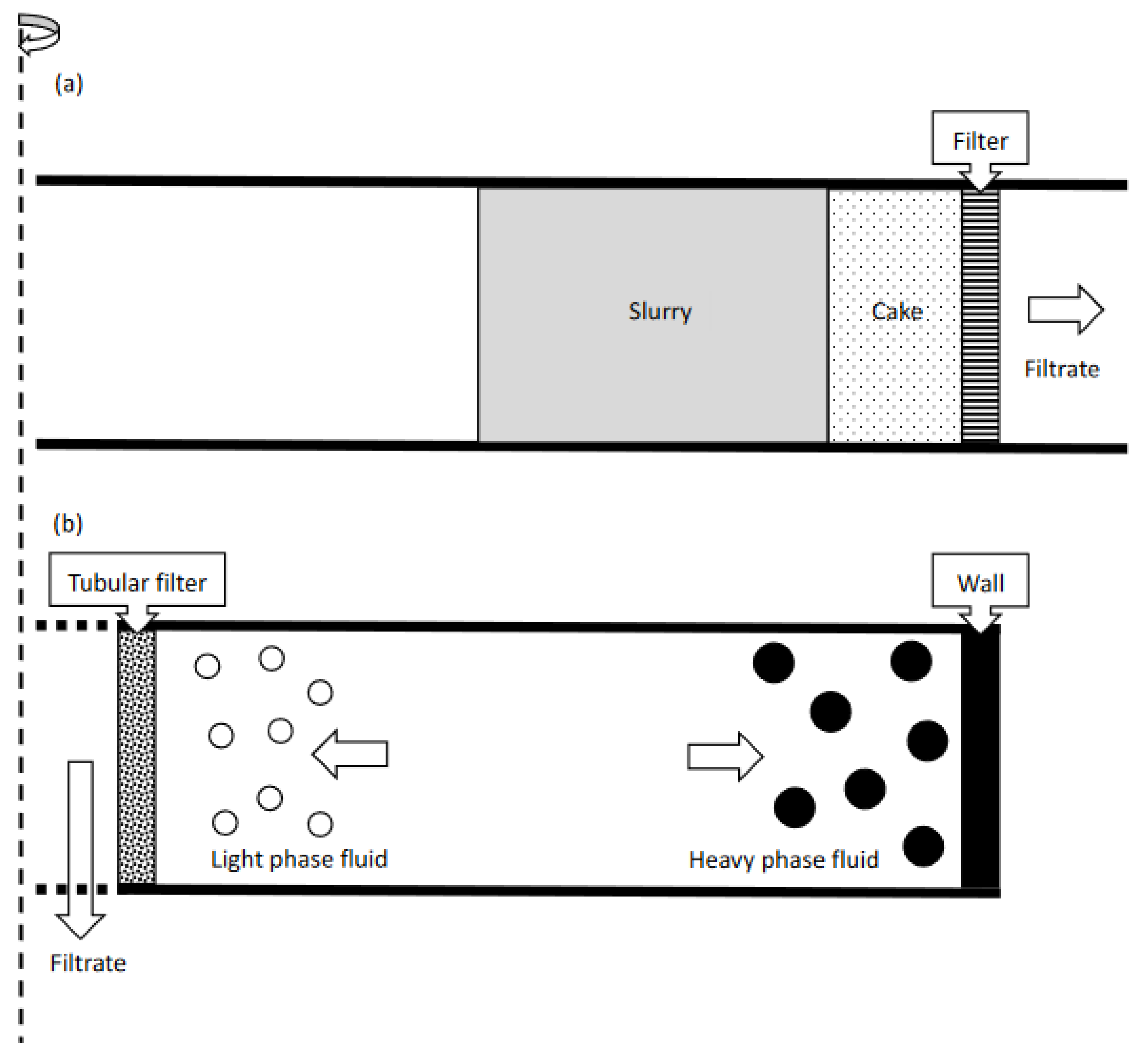
The filtration technique of the device developed in this study is quite different from traditional centrifugal filtration equipment. During centrifugal filtration using traditional equipment, the liquid and particles in the working fluid move in the same direction under the effect of centrifugal force. The particles are caught by the filter, whereas the liquid flows through the filter to achieve filtration. Figure 1a provides a schematic diagram of traditional centrifugal filtration.
Fu et al. [23] developed a new type of cyclone device for the sorting and classification of particles by means of a centrifugal force field, which has a multiproduct function. The centrifugal filtration device developed in this study is inspired by the cyclo-flow filtration method of [24,25]. When the suspension flows centrifugally around the central filter in the hydrocyclone, the strong shear force caused by crossflow filtration [26] reduces fouling, and the centrifugal force is somewhat effective in moving the particles away from the central filter. Therefore, increasing the centrifugal force could enhance the effectiveness of cyclo-flow filtration. The filter medium of the device developed in the present study is mounted in the center of the centrifugal chamber. During filtration, when the centrifugal chamber is full of working fluid, which is injected continuously, the particles and liquid in the solution move towards the centrifugal chamber wall under the effect of centrifugal force. The pressure difference between the continuous fluid inflow and the filtrate outlet is 1.5 bar, which compels the liquid to move towards the filter in the center of the centrifugal chamber, thus achieving filtration. Figure 1b shows the schematic diagram of the centrifugal filtration device proposed in this study.
2. Experimental Method
2.1. Materials and Filter
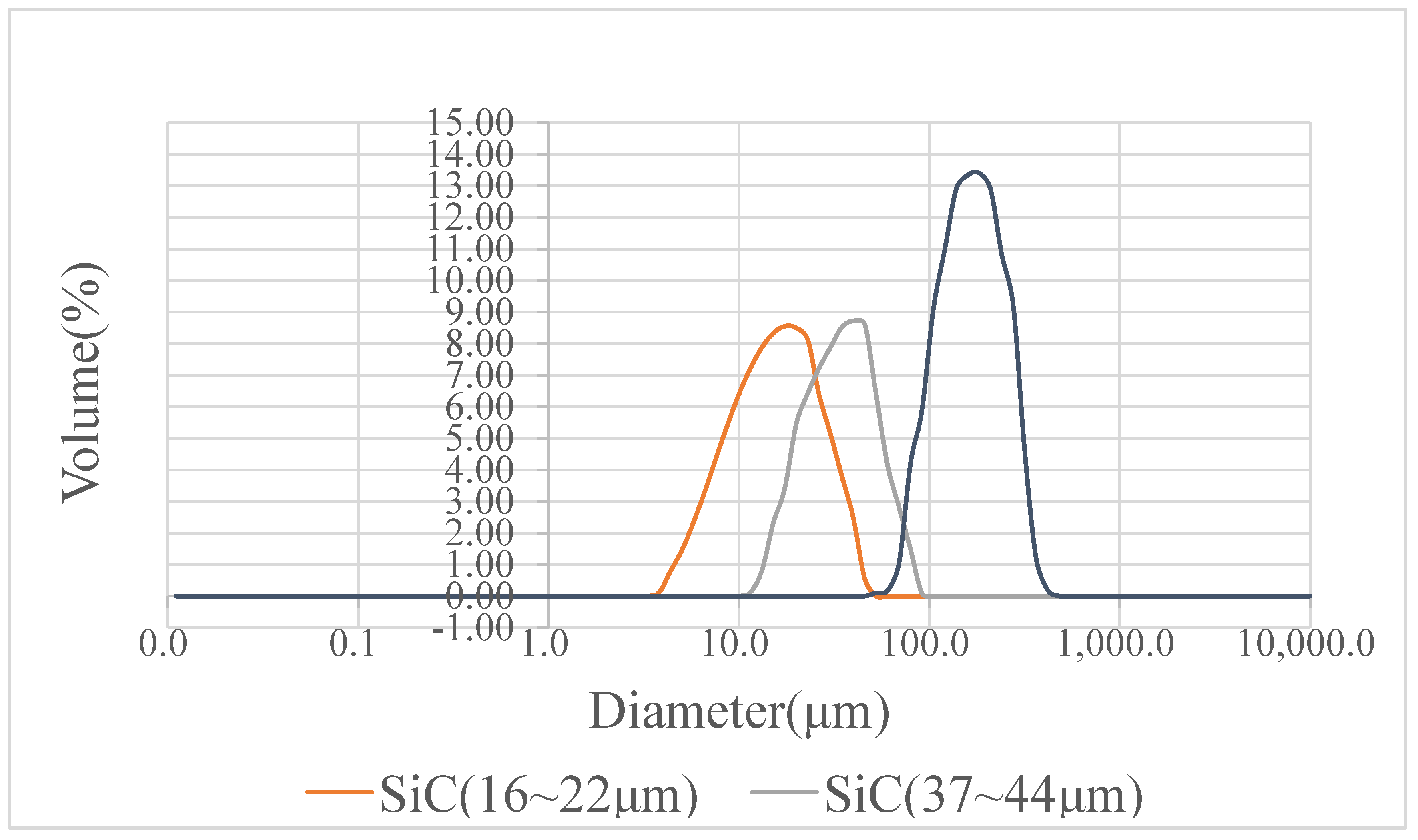
We used three kinds of powder in this study: silicon carbide with a particle size range of 16~22 μm, silicon carbide with a particle size range of 37~44 μm, and alumina oxide. Their densities were 3220 and 3900 kg/m3, respectively. The mean particle sizes measured by a particle size analyzer were 20, 40, and 160 μm, respectively. The size distribution is shown in Figure 2.
We used two filters for this experiment: an inorganic composite ceramic tubular membrane produced by the TAMI company, with a diameter of 1 cm and an average pore size of 1.4 μm, and the traditional PP organic filter element for water purifiers and water filters, with a diameter of 2.5 cm and an aperture of 5 μm.
2.2. Experimental Apparatus and Equipment
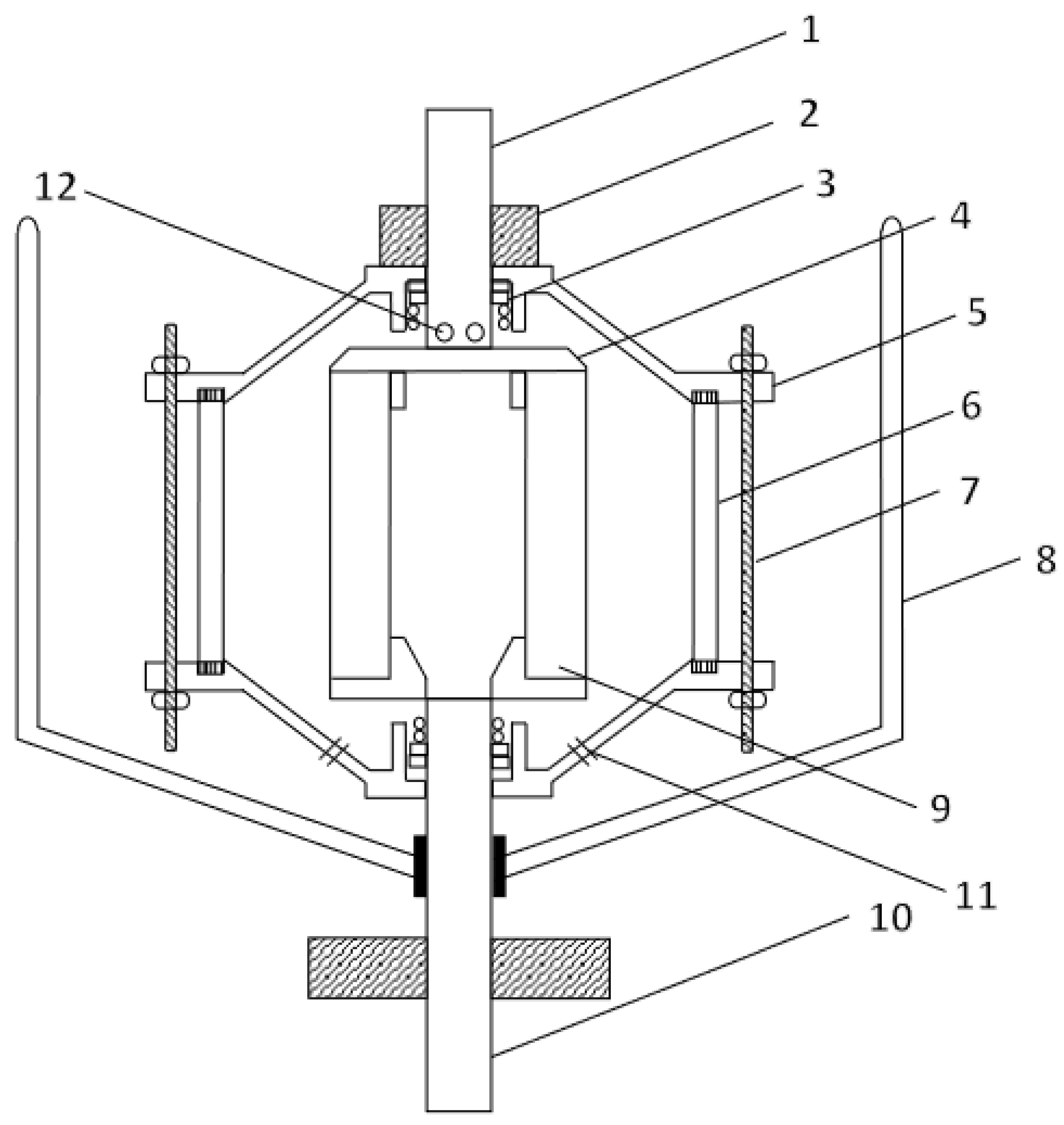
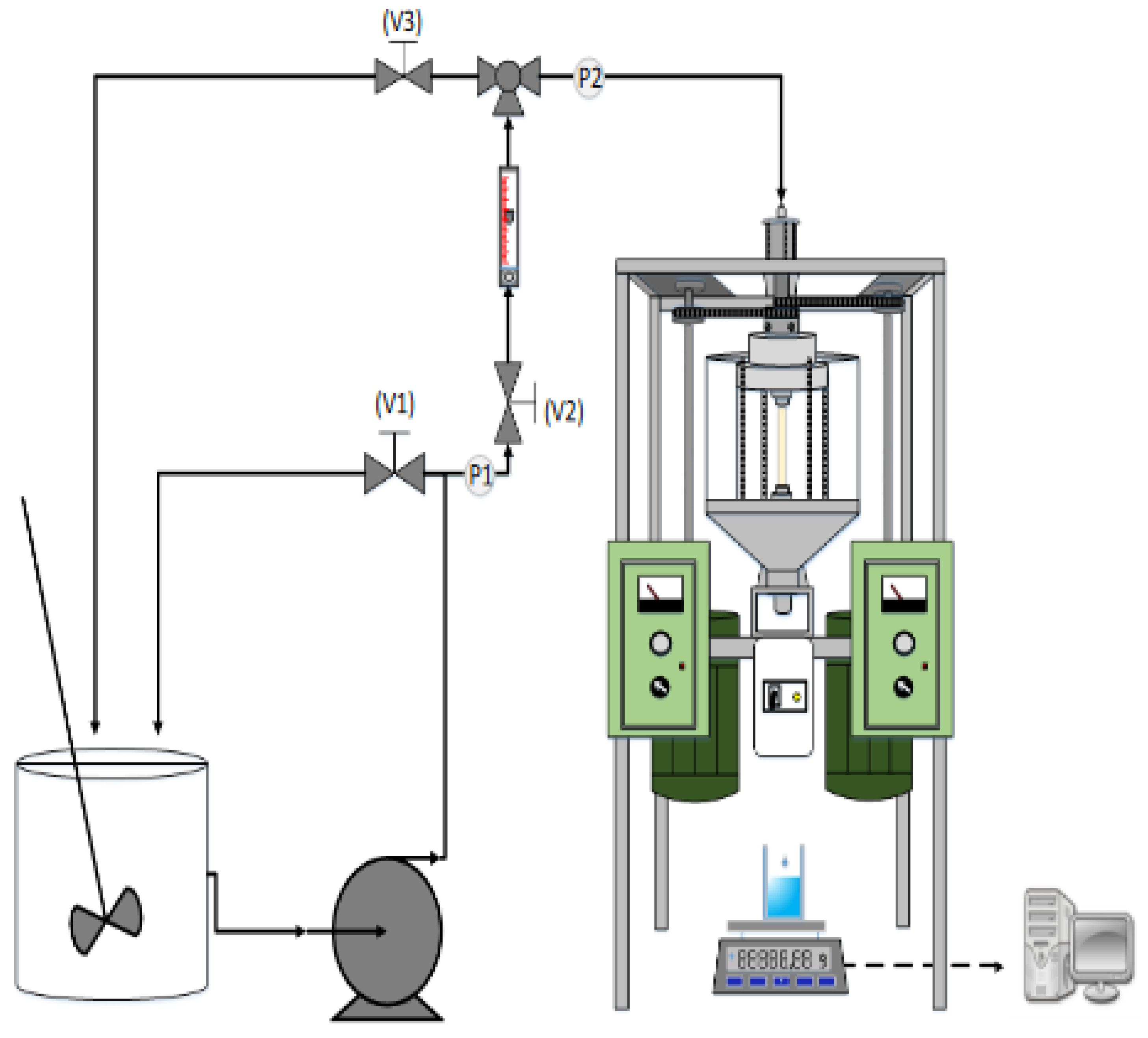
We used a TQ 400 pump produced by Walrus Pump Co., Ltd. and a Precisa series electronic balance (model XS 225A, for the precise weighing of drugs). For convenient observation of the working fluid rotation and the migration of particles in the filtration chamber, we used transparent polymethacrylate as a building material. Figure 3 shows a schematic diagram of the centrifugal filtration device. The diameter and height of the rotation chamber are 20 and 16 cm, respectively. Figure 4 shows the overall assembly of the centrifugal filtration device, including the relationships between various components of the system. The arrow represents the flow direction of the working fluid. When the working fluid is pressurized and delivered by the pump from the storage tank, it is split into the recirculating flow and the main stream. The recirculating flow returns to the barrel bath, whereas the main stream enters the centrifugal chamber and is filtered through the central tubular membrane, producing a clear and clean filtrate.
2.3. Experimental Setup and Operation
The experimental procedure for this centrifugal filtration device is described below: Make sure the valves V1 and V2 are turned on; switch on the centrifugal filtration device and adjust the rotation speed to the required experimental rotation speed. Slowly adjust the reflux valve (V1) and observe the feed pressure meter (P1) until the required experimental pressure (1.5 bar) is reached. Valve V3 controls the discharge of the gas from the filtration chamber. Open the balance software (Precisa) on a computer to record the amount of filtrate. Calculate the filtrate flux; collect, dry, and weigh the clear liquid; and analyze the data after the experiment.
3. Results and Discussion
3.1. Tubular Ceramic Membrane and Silicon Carbide Powder
3.1.1. Effect of Particle Size
We used three kinds of powder in this study: silicon carbide with a particle size range of 16~22 μm, silicon carbide with a particle size range of 37~44 μm, and alumina oxide. Their densities were 3220 and 3900 kg/m3, respectively. The mean particle sizes measured by a particle size analyzer were 20, 40, and 160 μm, respectively. The slurry had a weight percentage concentration of 0.3%, the inlet operating pressure was 1.5 bar, and the centrifugal chamber rotation speed was 2000 rpm. Figure 5 shows the filtrate flux rate comparison diagram.
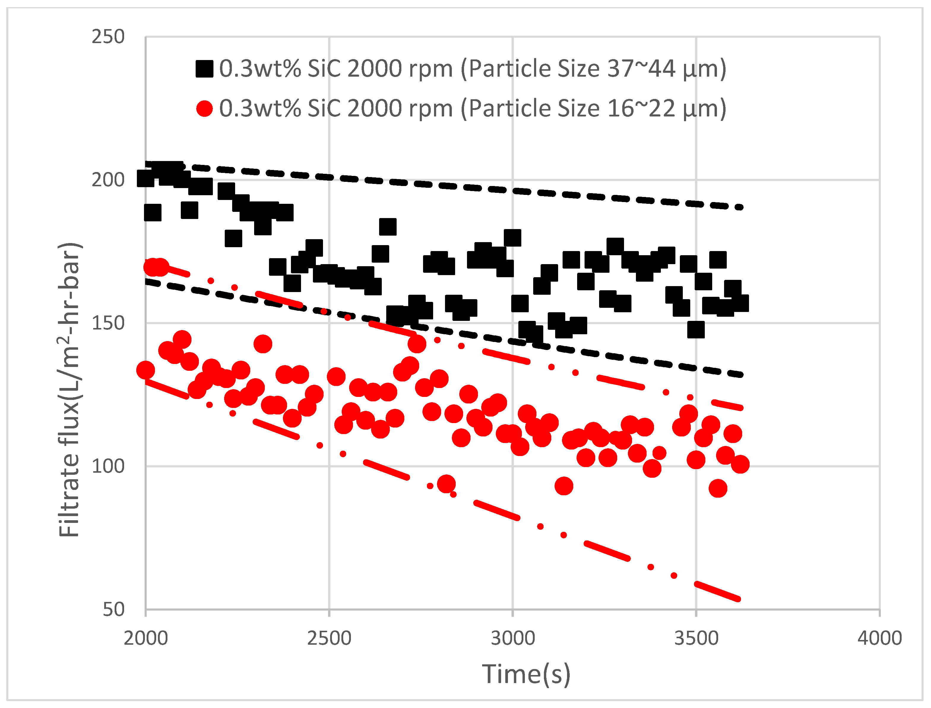
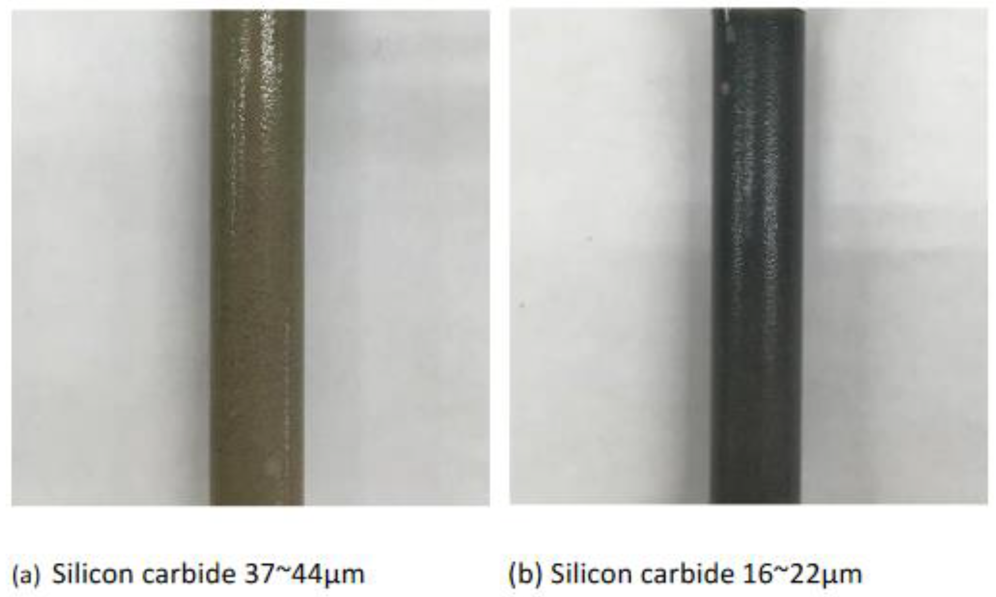
Figure 5 demonstrates that in the centrifugal chamber, larger powder particles were likely to move towards the polymethacrylate wall under the effect of centrifugal force. Particles were unlikely to move towards the tubular ceramic membrane in the center of the filtration chamber, and so the filtration cake accumulated on the filtration chamber wall, not on the membrane surface. The particles that were significantly influenced by the centrifugal force generally moved in the centrifugal direction, but a few particles still moved in the centripetal direction, resulting in a blocked filter and a decreased filtration rate. The filtrate flux rate decreased as the powder particle size decreased. After one hour, the terminal filtration rates were 147 and 100 L/m2-hr-bar. Shih [27] et al. used a rotational circular-plate ultrafiltration membrane filter to recycle cutting oil and remove the particles in the fouling cake attached to the membrane surface; they were able to maintain a cutting-oil filtrate flux rate above 6.7 L/m2/hr. Figure 6 shows the exterior view of the membrane fouling after the experiment, illustrating that the larger particles were more strongly influenced by the centrifugal force and were thus unlikely to move towards the central tubular membrane (light gray fouling in Figure 6a vs. dark black fouling in Figure 6b). The fouling problem was slight, so the filtration rate was relatively high.
3.1.2. Effect of Rotation Speed
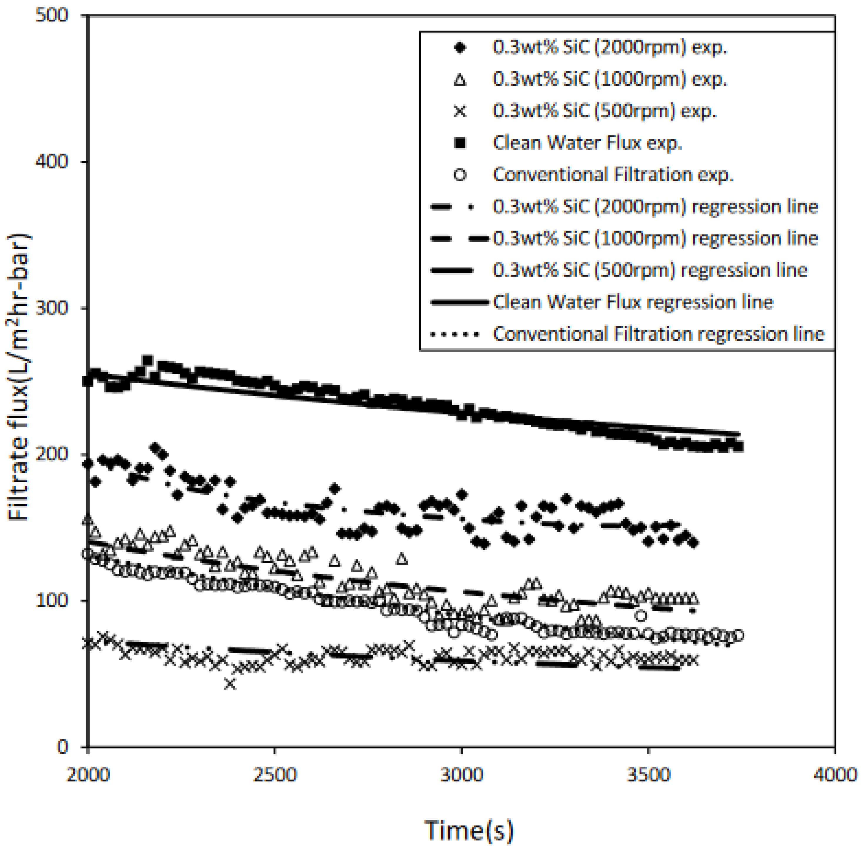
Under the operating conditions of an inlet pressure of 1.5 bar, a working fluid concentration of 0.3 wt%, and a particle size range of 37~44 μm, the centrifugal chamber rotation speed was adjusted to compare its effect on the filtrate flux rate. Figure 7 shows a comparison of the filtrate flux rate of the tubular membrane filtration module at different centrifugal chamber rotation speeds. After one hour, the filtrate flux rate at a rotation speed of 2000 rpm (158 L/m2-hr-bar) was 1.5 times higher than that at a rotation speed of 1000 rpm (100 L/m2-hr-bar) and 2.7 times higher than that at a rotation speed of 500 rpm (58 L/m2-hr-bar). Figure 7 also illustrates that under the same feed inlet operating pressure and working fluid concentration, the higher the centrifugal chamber rotation speed, the larger the separation factor (Fr). Therefore, the particles were more likely to move towards the wall of filtration chamber than towards the central tubular membrane, so the particles were unlikely to adhere to the membrane surface and more filtrate was obtained.
As shown in Figure 1b and Figure 4, the radii of the centrifugal chamber and the filter element are 10 and 0.5 cm, respectively. The filter is fixed, and the centrifugal chamber rotates. Therefore, there is enough distance for radial motion. According to Equation (3), when the order of magnitude of Vp is about 1 m/s and the order of magnitude of Vf is about 10−5 m/s, effective separation can be achieved. Nakakura et al. [20] designed a centripetal filtration device similar to that proposed in this study. However, their device did not have enough distance in the radial direction to allow separation.
3.1.3. Comparison between Filtrate Fluxes Rates of Proposed Centrifugal Filtration Device and Tubular Membrane Filtration Module
Figure 7 shows that when the rotation speed of the centrifugal filtration device was adjusted to 2000 rpm, the filtrate flux rate after one hour was 158 L/m2-hr-bar (solid diamond). The flux rate after one hour of clean water filtration was 207 L/m2-hr-bar (solid square). The flux rate after one hour of tubular membrane filtration decreased to 77 L/m2-hr-bar (open circle). Cleaning was conducted after each experiment, but residual SiC particles remained in the pipeline, so the filtration rate decreased when filtering clear water. The filtrate flux rate of the proposed device was lower than that of clean water by about 24%, whereas the tubular membrane filtration flux rate was almost 63% lower than that of clean water. This demonstrates that the proposed centrifugal filtration device is more effective than traditional tubular membrane filtration. When the rotation speed was 500 rpm (crosses in Figure 7), the centrifugal force was insufficient to carry the particles away from the filter, and the filtration rate was worse than traditional membrane filtration (data obtained using the same equipment with no rotation; open circles in Figure 7), perhaps owing to turbulence.
3.2. Organic Filter Element and Alumina Oxide Powder
3.2.1. Results for Proposed Centrifugal Filtration Device
Maintaining a constant feed pressure (1.5 bar) and slurry concentration, the filtration chamber rotation speed was adjusted to 2000 rpm. The filtrate flux rates are shown in Figure 8, which demonstrates that the filtrate flux rate after one hour was only 3% lower than that of clean water filtration. The amount of particles accumulated on the filter element at 2000 rpm was lower than that at 0 rpm. Because the particles in the filtration chamber are influenced by centrifugal force, they are unlikely to move towards the filter and adhere to it, meaning that this centrifugal filtration device is very effective.
3.2.2. Effect of Working Fluid Concentration
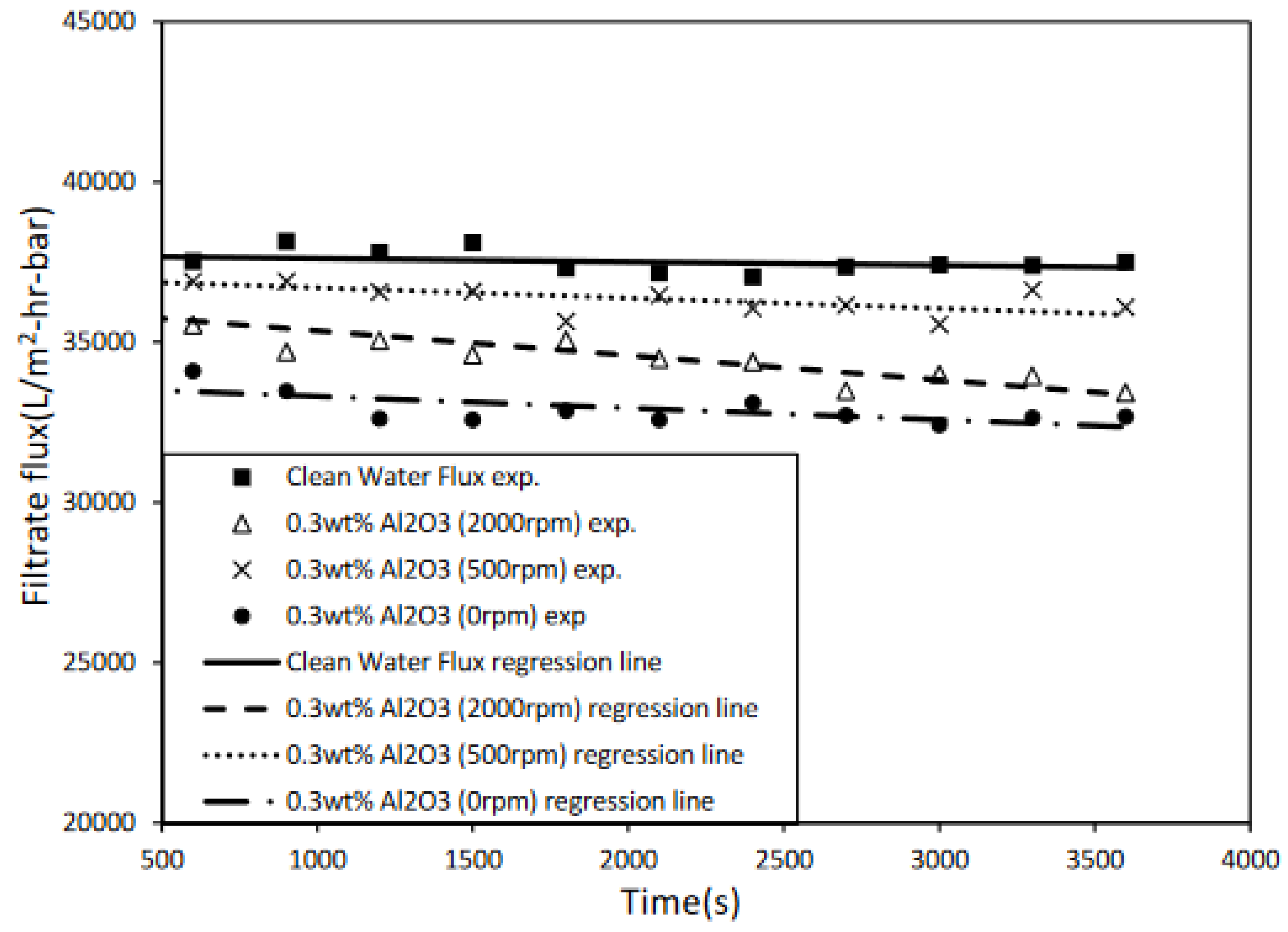
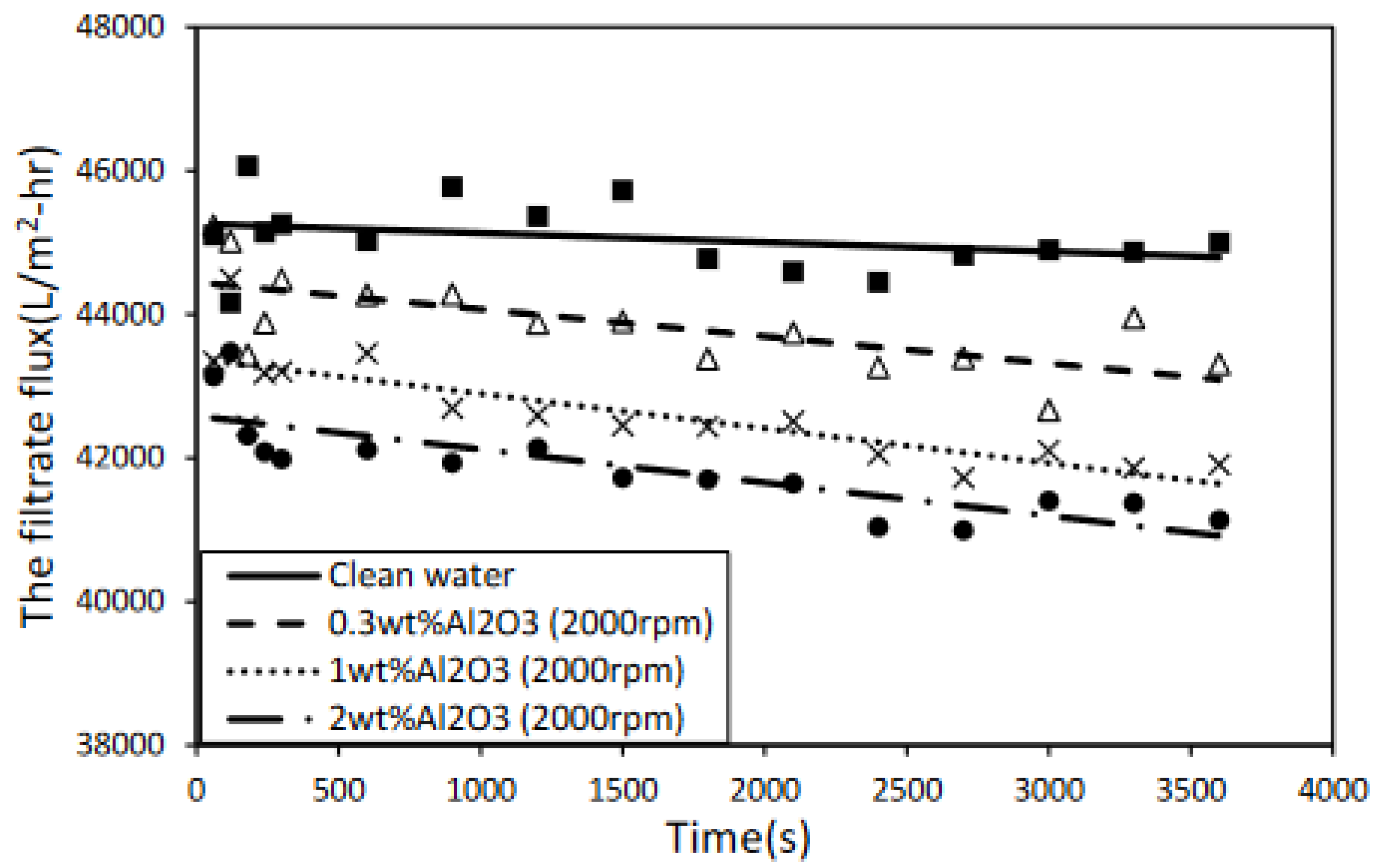
At a constant feed pressure (1.5 bar) and filtration chamber rotation speed (2000 rpm), the filtrate flux rate decreased as the concentration of working fluid increased. This trend can be observed in Figure 9. According to our calculations, the filtrate flux rate for a working fluid concentration of 0.3 wt% after one hour was 43,315 (L/m2-hr), only 3% lower than the clean water filtration flux rate of 44,485 (L/m2-hr). The filtrate flux rate of 1 wt% slurry after one hour of filtration was 41,915 (L/m2-hr), 6% lower than the clean water filtrate flux rate. The filtrate flux rate of 2 wt% slurry after one hour was 41,135 (L/m2-hr), lower than that of clean water filtration by almost 8%. The probability of particles moving towards the filter element in the filtration chamber increased with the working fluid concentration, meaning that the working fluid concentration influenced the filtrate flux rate.
4. Conclusions
Our testing of the proposed cyclo-flow centrifugal filtration device showed that when the powder particle size was large, the particles experienced greater centrifugal force and were unlikely to move towards the tubular membrane and adhere to its surface, so more filtrate was obtained. When the filtration chamber rotation speed was 2000 rpm, the filtrate flux rate was about 24% lower than that of clean water filtration, while the traditional tubular membrane filtration flux rate was about 63% lower. The filtrate flux rate of the proposed centrifugal filtration device is higher than that of traditional tubular membrane filtration. The probability of particles adhering to the membrane surface is reduced in long-term operation, so more filtrate can be obtained; thus, the proposed system is suitable for further development.
A higher rotation speed generated a greater centrifugal force, causing the particles to move towards the wall of the filtration chamber; hence, the filtration cake was unlikely to accumulate on the filter surface, and the amount of filtrate increased. This proves that the rotation speed influences the filtering effect of the proposed equipment: a higher rotation speed results in more filtrate, and a lower rotation speed results in less filtrate.
Author Contributions
Conceptualization, J.-M.W.; methodology, C.-C.L.; validation, C.-C.L. and J.-M.W.; investigation, J.-M.W.; data curation, C.-C.L.; writing—original draft preparation, C.-C.L.; writing—review and editing, J.-M.W.; supervision, J.-M.W. All authors have read and agreed to the published version of the manuscript.
Funding
This research received no external funding.
Institutional Review Board Statement
Not applicable.
Informed Consent Statement
Not applicable.
Data Availability Statement
Not applicable.
Acknowledgments
The authors would like to thank 7-Juice Co., Taiwan, and the Environmental Protection Administration of the Republic of China, Taiwan, under Contract No. EPA 109-A339, for financially supporting this research.
Conflicts of Interest
The authors declare no conflict of interest.
References
- Wang, M.; Sun, F.; Zeng, H.; Su, X.; Zhou, G.; Liu, H.; Xing, D. Modified Polyethersulfone Ultrafiltration Membrane for Enhanced Antifouling Capacity and Dye Catalytic Degradation Efficiency. Separations 2022, 9, 92. [Google Scholar] [CrossRef]
- Jha, P.K.; Khongnakorn, W.; Chawenjkigwanich, C.; Chowdhury, M.S.; Techato, K. Eco-Friendly Reduced Graphene Oxide Nanofilter Preparation and Application for Iron Removal. Separations 2021, 8, 68. [Google Scholar] [CrossRef]
- Zouboulis, A.I.; Peleka, E.N.; Ntolia, A. Treatment of Tannery Wastewater with Vibratory Shear-Enhanced Processing Membrane Filtration. Separations 2019, 6, 20. [Google Scholar] [CrossRef] [Green Version]
- Zhao, X.; Lai, E.P.C. Titania and Zinc Oxide Nanoparticles: Coating with Polydopamine and Encapsulation within Lecithin Liposomes—Water Treatment Analysis by Gel Filtration Chromatography with Fluorescence Detection. Separations 2018, 5, 13. [Google Scholar] [CrossRef] [Green Version]
- Zhang, Y.; Yuan, Z.; Bai, H.; Zhao, L.; He, L.; Shi, C. A Pilot-Scale Treatment of Steel Plant Wastewater by PVDF Hollow Fiber Ultrafiltration Membrane with Low Packing Density. Separations 2022, 9, 37. [Google Scholar] [CrossRef]
- Straube, C.; Meyer, J.; Dittler, A. Identification of Deposited Oil Structures on Thin Porous Oil Mist Filter Media Applying µ-CT Imaging Technique. Separations 2021, 8, 193. [Google Scholar] [CrossRef]
- Zhou, F.; Sun, G.; Han, X.; Zhang, Y.; Bi, W. Experimental and CFD study on effects of spiral guide vanes on cyclone performance. Adv. Powder Technol. 2018, 29, 3394–3403. [Google Scholar] [CrossRef]
- Fu, S.; Zhou, F.; Sun, G.; Yuan, H.; Zhu, J. Performance evaluation of industrial large-scale cyclone separator with novel vortex finder. Adv. Powder Technol. 2021, 32, 931–939. [Google Scholar] [CrossRef]
- Centrifugal Separators and Milk Standardization. Available online: https://dairyprocessinghandbook.tetrapak.com/chapter/centrifugal-separators-and-milk-standardization (accessed on 15 April 2022).
- Fukuyama, R.; Jami, M.S.; Tanaka, T.; Iwata, M. Consolidation behaviour of thick suspension in centrifugal dewatering with and without supernatant. Sep. Purif. Technol. 2015, 150, 223–228. [Google Scholar] [CrossRef]
- Li, L.; Ding, L.; Tu, L.; Wan, Y.; Clausse, D.; Lanoiselle, J.L. Recovery of linseed oil dispersed within an oil-in-water emulsion using hydrophilic membrane by rotating disk filtration system. J. Membr. Sci. 2009, 342, 70–79. [Google Scholar] [CrossRef]
- Jaffrin, M.Y. Dynamic shear-enhanced membrane filtration: A review of rotating disks, rotating membranes and vibrating systems. J. Membr. Sci. 2008, 324, 7–25. [Google Scholar] [CrossRef]
- Loginov, M.; Zierau, A.; Kavianpour, D.; Lerche, D.; Vorobiev, E.; Gésan-Guiziou, G.; Mahnic-Kalamiza, S.; Sobisch, T. Multistep centrifugal consolidation method for characterizationof filterability of aggregated concentrated suspensions. Sep. Purif. Technol. 2017, 183, 304–317. [Google Scholar] [CrossRef]
- Bouzerar, R.; Jaffrin, M.Y.; Lefevre, A.; Paullier, P. Concentration of ferric hydroxide suspensions in saline medium by dynamic cross-flow filtration. J. Membr. Sci. 2000, 165, 111–123. [Google Scholar] [CrossRef]
- Parnham, C.S., III; Davis, R.H. Protein recovery from cell debris using rotary and tangential crossflow microfiltration. Biotechnol. Bioeng. 1995, 47, 155–164. [Google Scholar] [CrossRef] [PubMed]
- Belfort, G. Diagnosis of membrane fouling using a rotating annular filter, 2. Dilute particle suspensions of known particle size. J. Membr. Sci. 1993, 77, 23–39. [Google Scholar] [CrossRef]
- Nuortila-Jokinen, J.; Nystrom, M. Comparison of membrane separation processes in the internal purification of paper mill water. J. Membr. Sci. 1996, 119, 99–115. [Google Scholar] [CrossRef]
- Schwille, J.A.; Mitra, D.; Lueptow, R.M. Design parameters for rotating cylindrical filtration. J. Membr. Sci. 2002, 204, 53–65. [Google Scholar] [CrossRef]
- Wereley, S.T.; Akonur, A.; Lueptow, R.M. Particle–fluid velocities and fouling in rotating filtration of a suspension. J. Membr. Sci. 2002, 209, 469–484. [Google Scholar] [CrossRef]
- Nakakura, H.; Tsubone, A.; Miura, K.; Osasa, K. Centrifugal ultrafiltration of protein solutions in a centripetal-flow cell. In Proceedings of the 10th Congress of Asian Pacific Confederation of Chemical Engineering, Kitakyushuu, Japan, 17–21 October 2004. [Google Scholar]
- Ginting, A.N.; Fukuyama, R.; Jami, M.S.; Tanaka, T.; Iwata, M. Improving slurry dewatering performance of basket centrifuge: Discharge of supernatant using bypass filter medium. J. Chem. Eng. Jpn. 2015, 48, 966–969. [Google Scholar] [CrossRef]
- Kamijo, J.; Sakai, K.; Suzuki, H.; Suzuki, K.; Kunitake, E.; Shimizu, M.; Kato, M. Identification and characterization of a thermostable pectate lyase from Aspergillus luchuensis var. saitoi. Food Chem. 2019, 276, 503–510. [Google Scholar] [CrossRef]
- Fu, P.; Wang, F.; Ma, L.; Yang, X.; Wang, H. Fine particle sorting and classification in the cyclonic centrifugal field. Sep. Purif. Technol. 2016, 158, 357–366. [Google Scholar] [CrossRef]
- Wu, R.M. Hydrocyclone Separator. U.S. Patent 8182684 B1, 22 May 2012. [Google Scholar]
- Vieira, L.G.M.; Barbosa, E.A.; Damasceno, J.J.R.; Barrozo, M.A.S. Performance Analysis and Design of Filtering Hydrocyclone. Braz. J. Chem. Eng. 2005, 22, 143–152. Available online: https://www.scielo.br/j/bjce/a/xhfQWc68r5YZhFgJsQ3f7hp/?format=pdf&lang=en (accessed on 15 April 2022). [CrossRef]
- Lin, J.Y.; Wu, R.M. Three Output Membrane Hydrocyclone: Classification and Filtration. Molecules 2019, 24, 1116–1132. [Google Scholar] [CrossRef] [PubMed] [Green Version]
- Shih, C.Y.; Gau, S.H.; Kuo, C.C.; Huang, C.Y.; Kuo, S.W. The Study of Rotational Ultrafiltration System for Recovery of Spent Cutting Oil from Solar Photovoltaic Cell Manufacturing Process. J. Appl. Sci. Eng. 2016, 19, 75–82. [Google Scholar]
Figure 1.
Schematic diagrams of (a) traditional centrifugal filtration and (b) the novel centrifugal filtration device proposed in this study.
Figure 1.
Schematic diagrams of (a) traditional centrifugal filtration and (b) the novel centrifugal filtration device proposed in this study.

Figure 2.
Size distribution of particles used in this study.

Figure 3.
Schematic diagram of the centrifugal filtration device. 1: fluid inlet pipe; 2: shaft seal pedestal; 3: shaft seal; 4: filter pedestal; 5: centrifugal chamber; 6: acrylic wall; 7: fixed screw; 8: receiving tank; 9: filter; 10: filtrate outlet; 11: centrifugate outlet; 12: fluid inlet pore.

Figure 4.
Overall assembly of the centrifugal filtration device.

Figure 5.
Filtrate flux rate comparison diagram.

Figure 6.
Exterior view of membrane fouling after experiment. (0.3 wt%, 2000 rpm).

Figure 7.
Filtrate flux rate at different centrifugal chamber rotation speeds.

Figure 8.
Filtrate flux rate at different centrifugal chamber rotation speeds.

Figure 9.
Filtrate flux rate at different concentrations of slurry.

Publisher’s Note: MDPI stays neutral with regard to jurisdictional claims in published maps and institutional affiliations. |
© 2022 by the authors. Licensee MDPI, Basel, Switzerland. This article is an open access article distributed under the terms and conditions of the Creative Commons Attribution (CC BY) license (https://creativecommons.org/licenses/by/4.0/).
Share and Cite
MDPI and ACS Style
Lin, C.-C.; Wu, J.-M. A Novel Centrifugal Filtration Device. Separations 2022, 9, 129. https://0-doi-org.brum.beds.ac.uk/10.3390/separations9050129
AMA Style
Lin C-C, Wu J-M. A Novel Centrifugal Filtration Device. Separations. 2022; 9(5):129. https://0-doi-org.brum.beds.ac.uk/10.3390/separations9050129
Chicago/Turabian StyleLin, Chia-Cheng, and Jung-Ming Wu. 2022. "A Novel Centrifugal Filtration Device" Separations 9, no. 5: 129. https://0-doi-org.brum.beds.ac.uk/10.3390/separations9050129
Note that from the first issue of 2016, this journal uses article numbers instead of page numbers. See further details here.