
Classification Performance of a Novel Hydraulic Classifier Equipped with a W-Shaped Reflector


College of Mechanical & Electronic Engineering, Shandong University of Science and Technology, Qingdao 266590, China
*
Author to whom correspondence should be addressed.
Separations 2022, 9(8), 212; https://0-doi-org.brum.beds.ac.uk/10.3390/separations9080212
Submission received: 15 July 2022
/
Revised: 31 July 2022
/
Accepted: 7 August 2022
/
Published: 10 August 2022
(This article belongs to the Special Issue Research on Separation Performance of Separator)
Abstract
:In the present research, we propose the use of a novel hydraulic classifier equipped with a W-shaped reflector to enhance classification performance. The effects of the structural dimensions of a W-shaped reflector on the flow field of a classifier and its classification performance were investigated using numerical simulations and experiments. The results demonstrate that the reflection of the W-shaped reflector results in the return of the feed material back to the classification cavity. After this, the materials are mixed with a rising water flow in order to avoid the settlement of particles. Thus, the particles can stay longer in the classification cavity, facilitating the generation of a suspension bed and effectively improving the classification efficiency and accuracy. Our data indicates that the overall classification efficiency of the classifier embedded with the W-shaped reflector was 11.19% higher than that of a traditional classifier. Our results provide a reference for classifier optimization.
1. Introduction
A hydraulic classifier is a device that separates a mixture of mineral particles into two different particle size ranges, which are identified as coarse and fine particles. These devices use the differences in the sedimentation speed of mineral particles. Hydraulic classifiers display several advantages including stable operation, ease of use, small size, and high classification efficiency, among others. For this reason, they have been widely used in various fields such as mineral processing engineering [1,2].
The structural features of classifiers have attracted significant attention because of their effect on classification performance. For instance, Tripathy et al. [3] developed a liquid–solid fluidized bed classifier with a baffle structure. These researchers achieved a significant vertical stratification of materials, improving classification efficiency. Laleh et al. [4] proposed a symmetric-nozzle classifier, where the nozzle produces powerful rotational flows. Because of this, the minerals can be sorted and classified several times, enhancing the classification accuracy. Mou et al. [5] proposed a highly efficient rotor classifier, and the ANSYS Fluent 19.0 software (ANSYS, Inc., Canonsburg, PA, USA) was used to simulate and investigate the effects of parameters such as rotor shape and the number of blades on the internal flow field and classification performance. Galvin et al. [6] reported that the REFLUXTM classifier with a 3 mm channel spacing showed a higher recovery rate than that with a 6-mm channel spacing. Carpenter et al. [7] combined the REFLUXTM classifier with a centrifuge to separate ultra-fine Si powders with particle sizes of 0–100 µm. With this device, cut sizes were changed from 20 μm down to 5 μm. Jiang et al. [8] investigated the effect of feed position on the classification performance of a fluidized bed. They hypothesized that classification performance was higher when materials were fed at the top or the central part of the bed, as compared to at the bottom. Zhang et al. [9,10] proposed a damping pulsation interference bed classifier. By adding a damping block inside the classification cavity, the turbulence intensity inside the classification cavity was effectively reduced, and the flow field was stabilized. Wei et al. [11] proposed a novel liquid–solid fluidized classifier embedded with an inclined plate, which improved the flow pattern inside the classification cavity and enhanced particle classification. Chen et al. [12] showed through experimental and numerical simulation results that the presence of a limited number of baffles in the fluidized bed can reduce the residence time of particles without affecting the average residence time. Sun et al. [13] effectively improved the classification accuracy by changing the feeding position of a traditional cyclonic classifier. Wang et al. [14,15] designed a three-product liquid–solid fluidized bed classifier. In this case, three types of products with different particle grades were obtained after three independent classification stages. Additionally, a classifier with a parallel plate was introduced in the classification cavity [16,17,18,19]. As a result, the mineral particle settling area in the classification cavity increased, improving the classification efficiency and accuracy. In addition, by adding a W-shaped reflector in the interference bed, the classification performance was augmented [20,21,22].
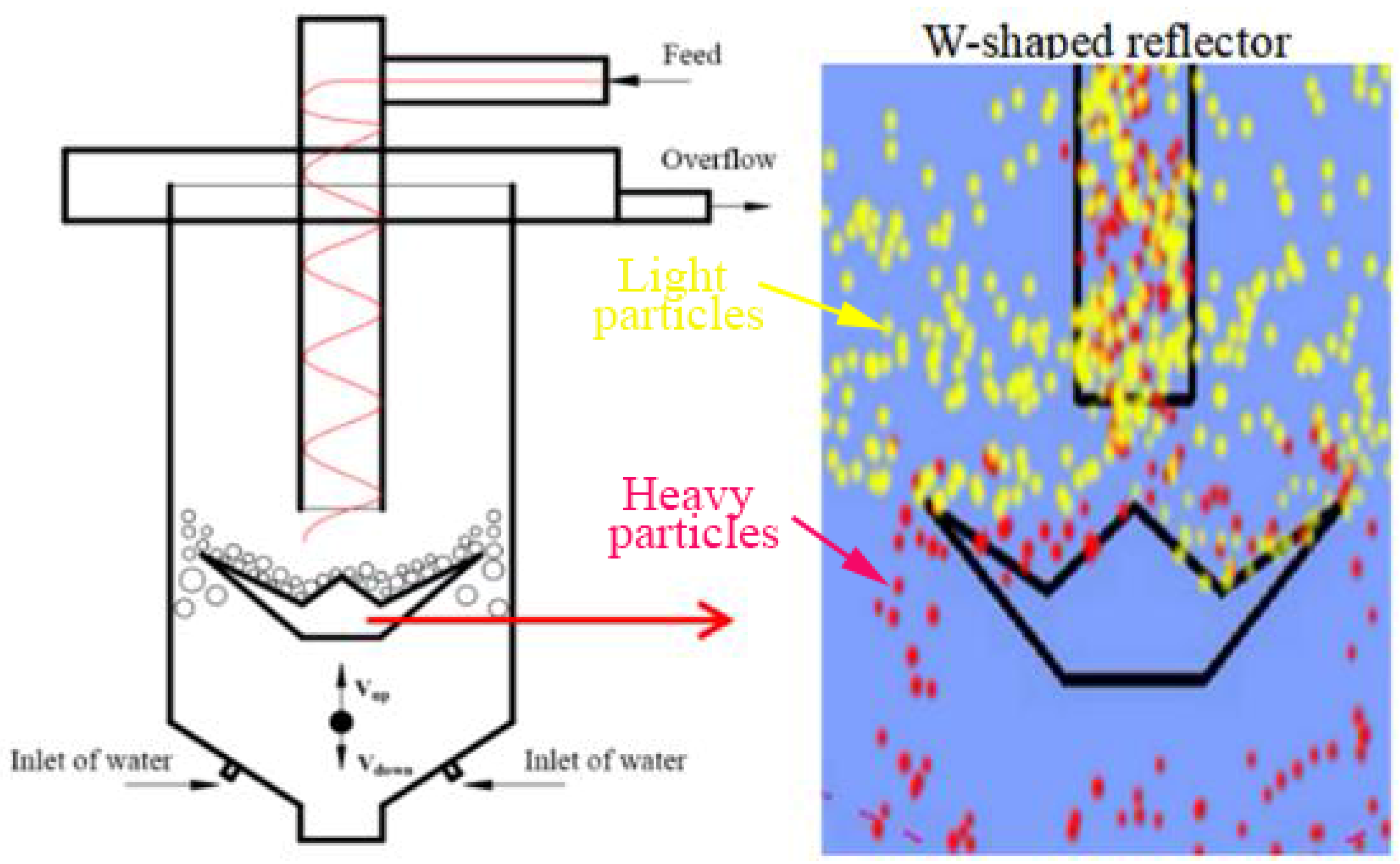
In summary, different classification devices have been proposed to enhance classification accuracy and great advances have been achieved in the last years. However, classification mechanisms remain unclear. In the present study, we propose a novel hydraulic classifier embedded with a W-shaped reflector. This reflector was inserted in the classification cavity of a traditional classifier, and vertical feeding was changed to tangential feeding. Using this type of feeding, materials enter the classification cavity in a spiral way, which facilitates their complete dispersion in the classification cavity. In addition, the probability of an unstable flow field is reduced. Flow field instability is usually caused by the strong shock of vertical feeding. When materials pass through the embedded W-shaped reflector, they go back for a second time under the reflective effect of the reflector. The returned feed is mixed with rising water to form an interference settlement, extending the time the feed remains in the classification cavity, consequently enabling full classification and improving the classification accuracy. Figure 1 shows the structure of the classifier embedded with a W-shaped reflector.
Computational fluid dynamics (CFD) has been applied to the study of classifiers by many scholars [23,24,25], and its accuracy has been verified. In the present research, numerical simulation was performed using Computational Fluid Dynamics (CFD) to investigate the effects of the W-shaped reflector structure on the classification performance and to determine the optimized structure. Additionally, experimental verification was carried out.
2. Materials and Methods
2.1. Geometric Modeling and Grid Division
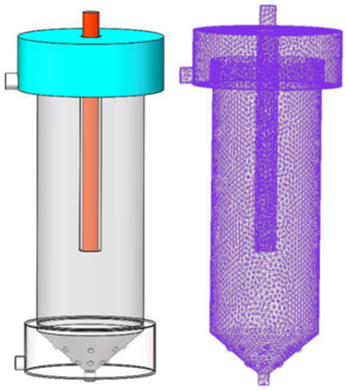
In order to compare the classification performance of a traditional classifier and the proposed classifier embedded with a W-shaped reflector, the same dimensions were used (see Figure 2 and Table 1). Figure 3 and Figure 4 show the model and the grid, respectively. Grid division revealed that the number of grid cells of the classifier embedded with a W-shaped reflector and the traditional classifier were 322,684 and 289,824, respectively.
2.2. Boundary Conditions and Solutions Using Numerical Simulations
The software ANSYS Fluent 14.5 (ANSYS, Inc., Canonsburg, PA, USA) was used for the numerical simulations. Water density and gravitational acceleration were set as 998 kg/m3 and 9.81 m/s2, respectively. The inlet was set as the velocity inlet, the outlet was set as the pressure outlet, and the wall boundary conditions were set as a NO-Slip-Wall. The solver was pressure-based, the algorithm was unsteady, and the discrete format was pressure PRESTO. In addition, a k-ε model was selected as the turbulence model. The inlet velocity of the classifier was set to 1.2 m/s, the top flow velocity to 0.9 m/s, and the inlet concentration to 20%.
2.3. Materials
In our experiments, magnetite with a density of 4500 kg/m3 was used. The accumulated contents of particles with sizes of 0–45, 45–125, and 125–300 μm were 22.1%, 49.2, and 28.7%, respectively. Table 2 shows the particle size distribution.
3. Simulation Results and Discussion
Classification Performances of a Classifier Embedded with a W-Shaped Reflector and a Traditional Classifier
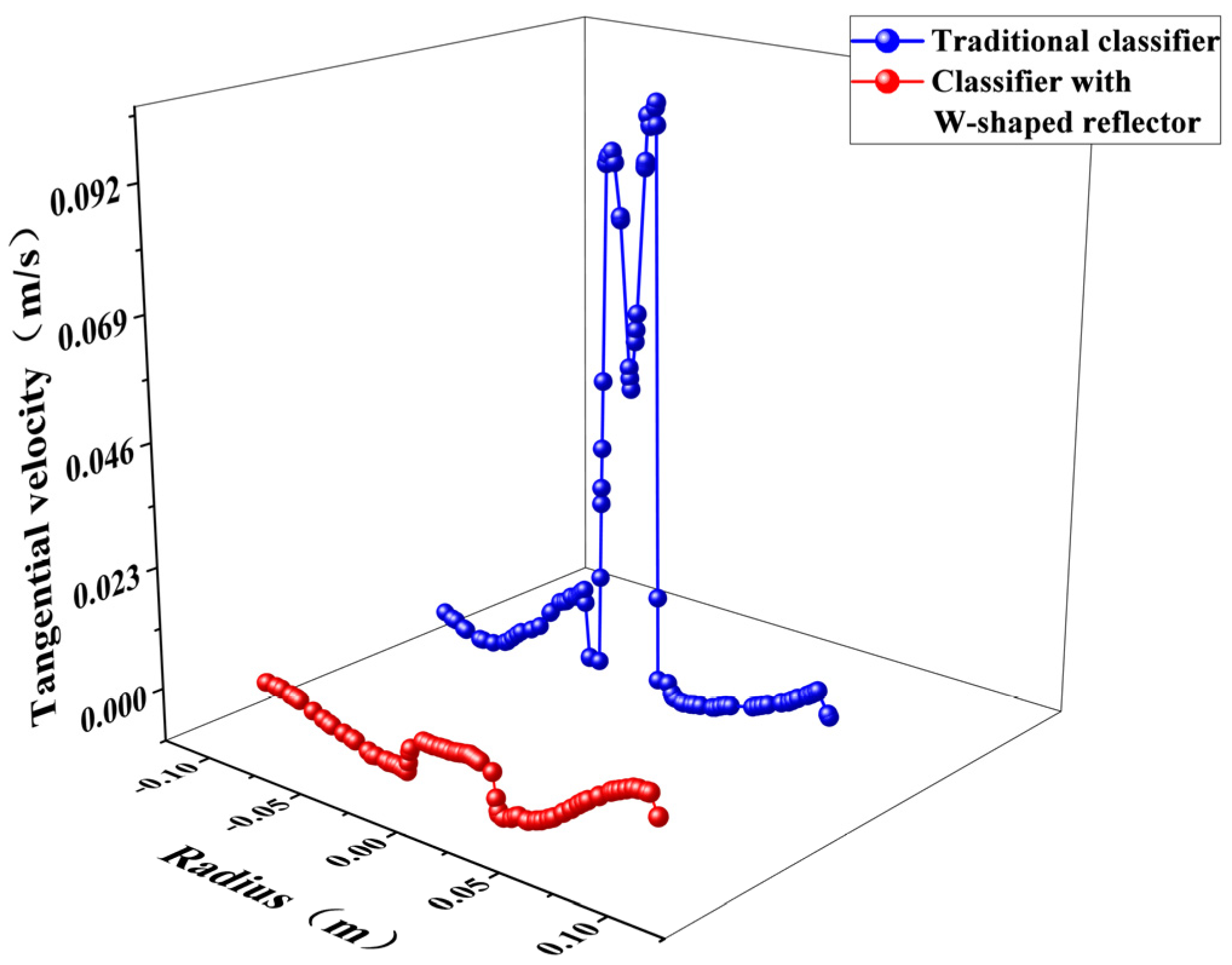
Figure 5 shows the tangential velocities of the classifier embedded with a W-shaped reflector and the traditional classifier. As observed, both classifiers exhibited consistent distributions of tangential velocities (symmetrical distribution along the axis). In addition, the tangential velocity of the classifier embedded with a W-shaped reflector was significantly greater than that of the traditional classifier. These results demonstrated that the classification performance of the classifier embedded with a W-shaped reflector was higher as compared to that of the traditional classifier. This probably occurred because the tangential velocity increased the centrifugal force, which facilitated particle dispersion and improved the classification performance.
The axial velocity had a significant effect on the classification performance. Figure 6 shows the axial velocities of both classifiers. As this figure shows, the axial velocity distribution in both classifiers was consistent. However, the axial velocity of the traditional classifier showed a U-shaped distribution, while that of the classifier embedded with a W-shaped reflector showed a W-shaped distribution. Additionally, the maximum axial velocity of the classifier embedded with a W-shaped reflector was significantly lower than that of the traditional classifier. The simulation results showed that the W-shaped reflector decreased the axial velocity of the feed materials, reducing their interaction with the top flow and improving the stability of the flow field. Moreover, with the decrease in axial velocity, the residence time of the particles in the classification cavity increased. This promoted the adequate stratification of the coarse and fine particles and improved the classification efficiency and accuracy.
Considering flow field stability and fluid fluctuations in the classification cavity, turbulent kinetic energy and dissipation rate play a decisive role in the efficient stratification of mineral particles. Hence, the effects of the turbulent kinetic energy and dissipation rate on the classification performance were investigated and the results are shown in Figure 7 (turbulent kinetic energy) and Figure 8 (dissipation rate). As the data showed, the turbulent kinetic energy and dissipation rate of materials when the newly proposed classifier was used were significantly lower than those obtained with the traditional classifier. This indicated that the flow field in the proposed classifier was stable and favored particle classification.
4. Experimental Study
4.1. Experimental System
In order to explore the classification performance of the classifier embedded with a W-shaped reflector, experiments were performed on the system shown in Figure 9. The system comprises a hydraulic classifier embedded with a W-shaped reflector, a slurry pump, a clean water pump, a pressure gauge, a flow meter, and a mixing device.
4.2. Classification Performances of the Two Classifiers
The classification performances of (a) the classifier embedded with a W-shaped reflector and (b) the traditional classifier were investigated. We performed different experiments to determine the underflow yield, overflow yield, classification efficiency, and distribution rate. The results are listed in Table 3 and Table 4.
As shown in Table 3, the content of fine particles (0–45 μm) in the overflow of the new classifier was 6.03% higher than that of the traditional classifier. In addition, fine particle (0–45 μm) content in the underflow of the proposed classifier was 3.67% lower than that of the traditional classifier. The coarse particle (125–300 μm) content in the new classifier underflow was 6.35% higher than that of the traditional classifier, while the coarse particle (125–300 μm) content in the overflow of the proposed classifier was 4.99% lower than that of the traditional classifier. During the sorting and classification processes, the classifier equipped with a W-shaped reflector initially dispersed and stratified the feed material through the tangential feeding spiral downward effect. Later, materials were stratified under the reflection of the W-shaped reflector, where the coarse and heavy particles moved downward into the underflow and the fine and light particles were carried by the rising top flow into the overflow. The yields of both the underflow coarse particles and the overflow fine particles significantly increased.
As shown in Table 4, the content of particles with sizes of 0–125 μm in the overflow of the classifier embedded with a W-shaped reflector was 4.72% higher than that of the traditional classifier. In addition, the content of particles with sizes of 0–125 μm in the underflow of the classifier embedded with a W-shaped reflector was 4.14% lower than that of the traditional classifier. Thus, the classification efficiency of the classifier embedded with a W-shaped reflector was 11.19% higher than that of the traditional classifier.
Figure 10 and Figure 11 show the particle size distributions in the underflow and overflow obtained in our experiments. As observed, the underflow materials obtained using the classifier embedded with a W-shaped reflector displayed a median particle size of 118 μm, which is 18 μm higher than that obtained using the traditional classifier. With respect to the underflow of the classifier embedded with a W-shaped reflector, the median particle size was 47 μm, which is 10 μm lower than that obtained with the traditional classifier. Therefore, the classifier supplied with a W-shaped reflector reduced the entrainment of fine particles in the underflow and coarse particles in the overflow. In summary, the classifier embedded with a W-shaped reflector showed advantages over the traditional classifier in terms of both classification efficiency and classification accuracy. In addition, it showed excellent fine particle classification performance.
4.3. Effects of Structural Dimensions of a W-Shaped Reflector on Classification Performance
The effects of different W-shaped reflector structures on classification performance were investigated. For this purpose, four W-shaped reflector structures were selected and the gap between the W-shaped reflector and the classification cavity wall was set to 5, 10, 25, and 40 mm (denoted as Structure 1, Structure 2, Structure 3, and Structure 4, respectively), as shown in Figure 12.
Figure 13 illustrates the underflow yields of the four classifiers with different reflector structures.
As the data show, the coarse particle (125–300 μm) content in the underflow increased as the gap between the reflector and the classification cavity wall increased. The highest value (26.31%) was reached when the gap was 25 mm. It was also observed that fine particle (0–45 μm) content in the underflow decreased as the gap between the reflector and the classification cavity wall increased. The minimum value was observed when the gap displayed a size of 25 mm. When the gap size was higher than 25 mm, the coarse and fine particle underflow content decreased and increased, respectively. These results indicated a gradual decrease in the underflow product grade.
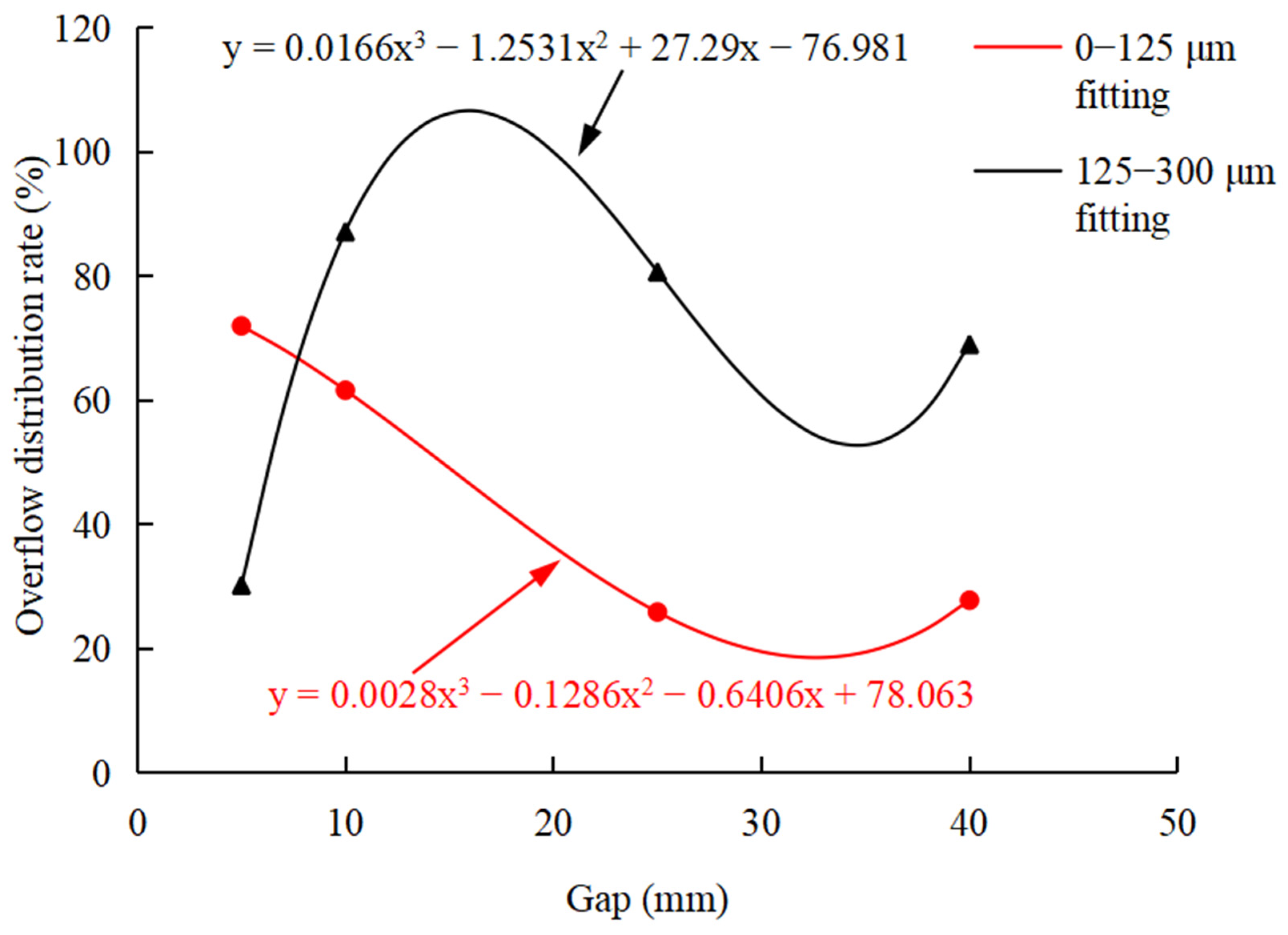
Figure 14 presents the overflow yields obtained when classifiers with four different reflector structures were used. As observed, fine particle (0–45 μm) content in the overflow increased as the gap between the reflector and the classification cavity wall also increased. The highest value was of 34.12% and was achieved when the gap size displayed a value of 25 mm. At this point, the smallest coarse particle content in the overflow was observed. When the gap size was higher than 25 mm, the content of fine and coarse particles in the overflow decreased and increased, respectively. This indicated a gradual decrease in the overflow product grade.
The data in Figure 15 indicates that the classification efficiency of fine particles (0–45 μm) in the overflow increased as the gap between the reflector and the classification cavity wall increased. The highest value (45.32%) was observed when the gap size was 25 mm. Figure 16 shows the product distribution in the overflow. The results show that the gap size between the reflector and the classification cavity wall significantly affected the particle size distribution in the classification cavity and classification accuracy. Thus, this parameter displayed a significant effect on the classification performance. In conclusion, gap selection was of great significance.
According to our data, the product grade decreased in the underflow and overflow product, regardless of gap size. This occurred because a large number of particles accumulated on the reflector when the gap was too small. In addition, because of particle collisions, coarse material was not able to settle down. The results indicate that when the gap was too small and the top flow velocity increased, large particles entered the overflow with the rising flow, contaminating the overflow product and resulting in a decrease in the overflow product grade. When the gap was too large, the refraction distance of the W-shaped reflector decreased, and the feed was not fully stratified. This caused fine particles to enter the underflow, causing a decrease in the underflow product grade.
5. Conclusions
- (1)
- Differently from a traditional classifier, the new classifier proposed in this paper was set up with a W-shaped reflector at the bottom of the feed port, the purpose of which was to make the slurry re-fold back twice through the reflection of the W-shaped reflector and mix with upwelling water to form an interference settlement, thereby improving the grading accuracy. Through simulation and comparative experiments, it was shown that the W plate classifier was an improvement over the traditional classifier in terms of the yield and grading efficiency.
- (2)
- Compared with the traditional classifier, the tangential speed of the W-shaped classifier increased, while the axial velocity, turbulence kinetic energy, and turbulence dissipation rate decreased. This indicates that the particles were subjected to greater centrifugal force in the W-shaped classifier, the residence time was longer, and the flow field was more stable.
- (3)
- The gap size of the W-shaped reflector and the sorting chamber had a significant impact on the grading efficiency and grading accuracy of the classifier, and the gap being too large or too small adversely affected the grading performance. In this experiment, the bottom miscarriage rate, overflow yield rate, and the grading efficiency of particles of −45 μm were best obtained at a gap of 25 mm. Therefore, a reasonable structural size was conducive to the generation of suspended layers and improved the grading performance.
Author Contributions
Conceptualization, Y.Z.; Methodology, Y.Z. and L.J.; Software, Y.D. and J.C.; Validation, Y.D. and J.C.; Formal Analysis, Y.Z. and L.J.; Investigation, Y.Z. and Y.D.; Resources, Y.D. and L.J.; Writing—original Draft Preparation, Y.Z.; Writing—review & Editing, Y.D. and L.J. All authors have read and agreed to the published version of the manuscript.
Funding
This research was funded by Natural Science Foundation of Shandong Province, China (ZR2020ME105) and National Natural Science Foundation of China (22108159).
Institutional Review Board Statement
Not applicable.
Informed Consent Statement
Not applicable.
Data Availability Statement
Not applicable.
Conflicts of Interest
The authors declare no conflict of interest.
References
- Zhu, X.; Liu, J.; Cao, C.; Dong, Y.; Wei, T. Numerical Studies on Teeter Bed Separator for Particle Separation. Energies 2020, 13, 2025. [Google Scholar] [CrossRef] [Green Version]
- Bu, X.N.; Ni, C.; Xie, G.Y.; Peng, Y.L.; Ge, L.H.; Sha, J. Preliminary study on foreign slime for the gravity separation of coarse coal particles in a teeter bed separator. Int. J. Miner. Process. 2017, 160, 76–80. [Google Scholar] [CrossRef]
- Tripathy, A.; Bagchi, S.; Biswal, S.K.; Meikap, B.C. Effect of fin type baffle on the particle hydrodynamics, separation and misplacement in a liquid solid fluidized bed separator. Adv. Powder Technol. 2019, 30, 428–438. [Google Scholar] [CrossRef]
- Laleh, S.; Movahedirad, S.; Sarbanha, A.A.; Sobati, M.A. A new hydraulic particle classifier: Experimental investigation and modeling. Sep. Purif. Technol. 2017, 174, 12–21. [Google Scholar] [CrossRef]
- Mou, X.L.; Jia, F.C.; Fang, Y.; Chen, C.W. CFD-Based Structural Optimization of Rotor Cage for High-Efficiency Rotor Classifier. Processes 2021, 9, 1148. [Google Scholar] [CrossRef]
- Galvin, K.P.; Iveson, S.M.; Zhou, J.; Lowes, C.P. Influence of inclined channel spacing on dense mineral partition in a REFLUX™ Classifier. Part 1: Continuous steady state. Miner. Eng. 2020, 146, 106112. [Google Scholar] [CrossRef]
- Carpenter, J.L.; Iveson, S.M.; Galvin, K.P. Ultrafine desliming using a REFLUX™ classifier subjected to centrifugal G forces. Miner. Eng. 2019, 134, 372–380. [Google Scholar] [CrossRef]
- Jiang, H.S.; Huang, L.; Lu, Q.C.; Zhao, Y.M.; Luo, Z.F.; Duan, C.L.; Dong, L.; Chen, Z.Q.; Lv, B.; Zhao, J.; et al. Separation performance of coal in an air dense medium fluidized bed at varying feeding positions. Fuel 2019, 243, 449–457. [Google Scholar] [CrossRef]
- Zhang, Y.S.; Zhang, L.; Liu, Y.Y.; Shi, C.C.; Wang, F.L. Experimental study of separation teston hindered pulsating teetered bed separator. Coal. Prep. Technol. 2013, 3, 17–20. [Google Scholar] [CrossRef]
- Yang, L.; Chen, J.T.; Zhang, L. Research on Feed Range of Teetered Bed Separator and Simulation. Coal. Prep. Technol. 2014, 33, 329–331. [Google Scholar] [CrossRef]
- Wei, L.B.; Liu, J.L. Coarse slime separation and numerical simulationof a new liquid-solid fluidized bed. J. Chin. Univ. Min. Technol. 2019, 48, 882–888. [Google Scholar] [CrossRef]
- Chen, K.; Bachmann, P.; Bück, A.; Jacob, M.; Tsotsas, E. CFD simulation of particle residence time distribution in industrial scale horizontal fluidized bed. Powder Technol. 2019, 345, 129–139. [Google Scholar] [CrossRef]
- Sun, Z.; Liang, L.; Liu, Q.; Yu, X. Effect of the particle injection position on the performance of a cyclonic gas solids classifier. Adv. Powder Technol. 2020, 31, 227–233. [Google Scholar] [CrossRef]
- Wang, K.B.; Li, Y.F.; Zhang, X.B.; He, C.Y.; Yu, Y.Y. Structural designand experimental study of liquid-solid fluidized bed for three products. Coal. Eng. 2014, 46, 115–118. [Google Scholar] [CrossRef]
- Zhang, X.B.; Li, Y.F.; Wang, K.B.; He, C.Y.; Yu, Y.Y. Study on Liquid Solid Fluidized Bed Applied to Tailings Repreparation. Coal. Eng. 2014, 46, 111–113. [Google Scholar] [CrossRef]
- Jayarathna, C.K.; Balfe, M.; Moldestad, B.M.E.; Tokheim, L.-A. Improved multi-stage cross-flow fluidized bed classifier. Powder Technol. 2019, 342, 621–629. [Google Scholar] [CrossRef]
- Galvin, K.P.; Nguyentranlam, G. Influence of parallel inclined plates in a liquid fluidized bed system. Chem. Eng. Sci. 2002, 57, 1231–1234. [Google Scholar] [CrossRef]
- Galvin, K.P.; Doroodchi, E.; Callen, A.M.; Lambert, N.; Pratten, S.J. Pilot plant trial of the reflux classifier. Miner. Eng. 2002, 15, 19–25. [Google Scholar] [CrossRef]
- Bondarenko, A.O. Modeling of interaction of inclined surfaces of a hydraulic classifier with a flow of solid particles. Sci. Bul. Nat. Min. Univ. 2018, 4, 13–20. [Google Scholar] [CrossRef] [Green Version]
- Zhang, Y.K.; Cao, J.Z.; Liu, P.K.; Li, X.Y.; Yang, Y.H.; Wang, H. Performance analysis of a new teetered bed separator with W-type reflector. J. Min. Saf. Eng. 2020, 37, 207–214. [Google Scholar] [CrossRef]
- Zhang, Y.K.; Cao, J.Z.; Liu, P.K.; Yang, M.; Zheng, X.F. Numerical Simulation and Experimental Study of New Hydraulic Classifier. Met. Mine 2019, 6, 168–172. [Google Scholar] [CrossRef]
- Zhang, X.D.; Fan, M.Q. Development and test study on a new type of separation classifier. Chin. Min. Mag. 2016, 25, 159–163. [Google Scholar] [CrossRef]
- Yang, X.; Yang, G.; Liu, P.; Li, X.; Jiang, L.; Zhang, J. Study on the Desliming Performance of a Novel Hydrocyclone Sand Washer. Separations 2022, 9, 74. [Google Scholar] [CrossRef]
- Yi, H.-W.; Kwon, J.-Y.; Lee, Y.-W.; Kang, M.-C. Optimization of the Outlet Flow Ratio of Mini-Hydrocyclone Separators Using the Full Factorial Design Method to Determine the Separation Efficiency. Separations 2021, 8, 210. [Google Scholar] [CrossRef]
- Galletti, C.; Rum, A.; Turchi, V.; Nicolella, C. Numerical analysis of flow field and particle motion in a dynamic cyclonic selector. Adv. Powder Technol. 2020, 31, 1264–1273. [Google Scholar] [CrossRef]
Figure 1.
Diagram of the proposed classifier embedded with a W-shaped reflector.

Figure 2.
Structural diagram of a classifier.

Figure 3.
Traditional classifier.

Figure 4.
Novel classifier embedded with a W-shaped reflector.

Figure 5.
Tangential velocities of the two classifiers.

Figure 6.
Axial velocities of the two classifiers.

Figure 7.
Turbulent kinetic energy of the two classifiers.

Figure 8.
Turbulent dissipation rate of the two classifiers.

Figure 9.
Diagram of the system used in the experiments: (1) classifier embedded with a W-shaped reflector; (2) pressure gauge; (3) flow meter; (4) mixer; (5) mixing tank; (6) valve; (7) slurry pump; and (8) clean water tank.
Figure 9.
Diagram of the system used in the experiments: (1) classifier embedded with a W-shaped reflector; (2) pressure gauge; (3) flow meter; (4) mixer; (5) mixing tank; (6) valve; (7) slurry pump; and (8) clean water tank.

Figure 10.
Particle size in the underflow of the two classifiers.

Figure 11.
Particle size in the overflow of the two classifiers.

Figure 12.
Structural diagram of the W-shaped reflector.

Figure 13.
Underflow yield.

Figure 14.
Overflow yield.

Figure 15.
Classification efficiency of fine particles (0–45 μm) in the overflow.

Figure 16.
Overflow distribution.


Table 1.
Classifier parameters.
| Structure | Value | Structure | Value |
|---|---|---|---|
| Length of feed pipe h1 (mm) | 550 | Diameter of overflow inlet d2 (mm) | 30 |
| Length of classification cavity H1 (mm) | 500 | Diameter of water inlet d3 (mm) | 4 |
| Diameter of feed pipe D (mm) | 30 | Diameter of tangential inlet d4 (mm) | 15 |
| Diameter of underflow inlet do (mm) | 20 | Diameter of reflector bottom d5 (mm) | 90 |
| Diameter of water inlet bin d1 (mm) | 20 | Diameter of reflector top d6 (mm) | 165 |
Table 2.
Particle size distribution.
| Particle Size (μm) | Interval Content (%) | Accumulated Content (%) |
|---|---|---|
| 0–15 | 1.32 | 1.32 |
| 15–30 | 5.63 | 6.95 |
| 30–45 | 15.15 | 22.1 |
| 45–75 | 16.35 | 38.45 |
| 75–90 | 13.34 | 51.79 |
| 90–125 | 19.51 | 71.3 |
| 125–150 | 9.61 | 80.91 |
| 150–180 | 6.35 | 87.26 |
| 180–212 | 5.24 | 92.5 |
| 212–250 | 3.26 | 95.76 |
| 250–300 | 4.24 | 100 |
Table 3.
Experimental data.
| Size Range | Traditional Classifier | Classifier with W-Shaped Reflector | |||
|---|---|---|---|---|---|
| Underflow | Overflow | Underflow | Overflow | ||
| Content (%) | 60.32 | 8.32 | 62.35 | 9.21 | |
| Productivity (%) | 0–45 μm | 8.35 | 24.21 | 4.68 | 30.24 |
| 45–125 μm | 11.62 | 16.83 | 10.37 | 14.36 | |
| 125–300 μm | 25.34 | 13.65 | 31.69 | 8.66 | |
| Yield (%) | 13.68 | 86.32 | 11.35 | 88.68 | |
Table 4.
Classification performances of the traditional classifier and the classifier embedded with a W-shaped reflector.
Table 4.
Classification performances of the traditional classifier and the classifier embedded with a W-shaped reflector.
| Classifier | The Content of 100–125 μm Particles/% | Classification Efficiency/% | ||
|---|---|---|---|---|
| Feed | Overflow | Underflow | ||
| Traditional classifier | 71.3 | 90.62 | 45.32 | 54.14 |
| Classifier embedded with a W-shaped reflector | 71.3 | 95.34 | 41.18 | 65.33 |
Publisher’s Note: MDPI stays neutral with regard to jurisdictional claims in published maps and institutional affiliations. |
© 2022 by the authors. Licensee MDPI, Basel, Switzerland. This article is an open access article distributed under the terms and conditions of the Creative Commons Attribution (CC BY) license (https://creativecommons.org/licenses/by/4.0/).
Share and Cite
MDPI and ACS Style
Zhang, Y.; Duan, Y.; Jiang, L.; Cao, J. Classification Performance of a Novel Hydraulic Classifier Equipped with a W-Shaped Reflector. Separations 2022, 9, 212. https://0-doi-org.brum.beds.ac.uk/10.3390/separations9080212
AMA Style
Zhang Y, Duan Y, Jiang L, Cao J. Classification Performance of a Novel Hydraulic Classifier Equipped with a W-Shaped Reflector. Separations. 2022; 9(8):212. https://0-doi-org.brum.beds.ac.uk/10.3390/separations9080212
Chicago/Turabian StyleZhang, Yuekan, Yaoxu Duan, Lanyue Jiang, and Jingzhen Cao. 2022. "Classification Performance of a Novel Hydraulic Classifier Equipped with a W-Shaped Reflector" Separations 9, no. 8: 212. https://0-doi-org.brum.beds.ac.uk/10.3390/separations9080212
Note that from the first issue of 2016, this journal uses article numbers instead of page numbers. See further details here.