Scanning Angle Magnification with Compact Reflective Optics for Light Detection and Ranging


Department of Photonics, Institute of Electro-Optical Engineering, College of Electrical and Computer Engineering, National Yang Ming Chiao Tung University, Hsinchu 300, Taiwan
*
Author to whom correspondence should be addressed.
Photonics 2022, 9(2), 59; https://0-doi-org.brum.beds.ac.uk/10.3390/photonics9020059
Submission received: 14 December 2021
/
Revised: 14 January 2022
/
Accepted: 20 January 2022
/
Published: 24 January 2022
(This article belongs to the Special Issue Optical Sensing)
Abstract
:The function of lidar requests a large scanning angle for a wide field of view and a well calibrated collimation of the laser beam for distant sensing. Besides meeting the required functionality, the compact form factor of the whole optical system is also highly desirable for the ease of being installed in mobile systems. In corresponding to the currently developed phase array laser which can achieve beam scanning without mechanical movement but still with a small scanning angle, a compact optics consisting of only two reflective surfaces has been proposed to magnify the scanning angle of a laser beam up to seven times while keeping the divergence of the laser beam smaller than 8 mrad for some short distance applications. The prototype has been prepared and evaluated with the expected performance.
1. Introduction
Lidar, acronym for light detection and ranging, is a device which sends out a laser signal and gathers information with the detection of the light bouncing back from objects [1,2,3]. This technology has been widely used for 3D mapping in various applications such as land structure and archaeology. In recent years, lidar has become a key technology for advanced driver assistance systems (ADAS) [4,5,6,7], and even for autonomous vehicles [8,9,10]. The autonomous vehicle, in a broader sense, includes robots and drones.
If considering the application for vehicles, the compactness would be a major concern. Some experimental prototypes of autonomous vehicles on the road are equipped with a big chunk of lidar on the roof [11,12], which would be considered not adequate for commercial applications in the long-term. The main source of the big volume is the mechanical mechanism for scanning the laser beam to cover the full 360 degree of the surroundings. Most recent developments go for solid state lidar which achieves laser beam scanning without mechanical movement, mostly based on the concept of a phase array [13,14,15,16]. However, with this kind of mechanism, the scanning angle of the laser beam is still quite small, with a range of approximately 6 to 12 degree [17,18,19]. Even with the strategy of equipping an array to cover a wider field of view, the scanning angle is still too small to be a cost effective solution. Therefore, the magnification of the scanning angle is an important supplementary technology.
There have been quite a few optical solutions for the magnification of a laser beam scanning angle, including a rotation member [20] and MEMS lidar [21,22]. However, those solutions mostly have complicated optics or a light path, which are normally associated with a big form factor. Therefore, the exploit of those solutions for solid state lidar will lead to a result which contradicts the main purpose of introducing a phase array scanning mechanism for lidar.
In this paper, compact optics composed of only two reflective surfaces are proposed. The function of the optical system is not only magnification of the scanning angle, but also keeping the collimation of the laser beam for short distance remote sensing. Furthermore, the proposed optics is not just compact due to its light path arrangement, but also potentially viable to be integrated with the phase array laser source and becomes a highly compact micro-opto-electro-mechanical system due to its feature of a fully reflective surface. Section 2 of the paper describes the conceptual design, and Section 3 and Section 4 present the details of design optimization and prototype evaluation, respectively. Finally, Section 5 concludes the paper with the results.
2. Conceptual Design of Scanning Angle Magnification with Reflective Optics
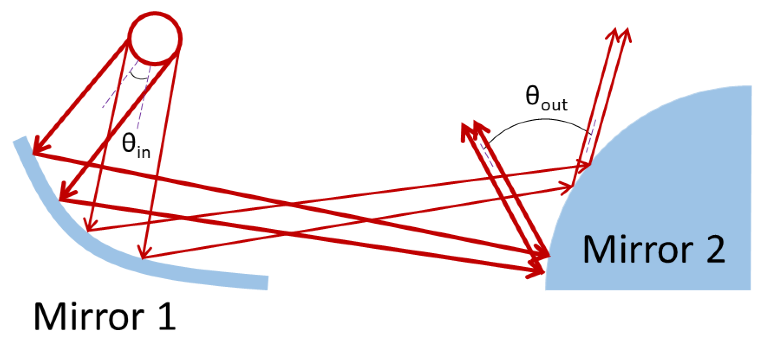
When scanning a laser beam over a planar mirror, the scanning angle will remain the same after the beam is reflected from the mirror. However, if the mirror is a convex one, the scanning angle will become larger after being reflected. Therefore, a convex mirror can work as the simplest optics for scanning angle magnification. The major issue with this approach is that the laser beam itself will also experience a local convex surface which makes the reflected beam more diverging. As the diverging beam propagates through a long distance, the resolution of the lidar will be significantly reduced. In order to compensate for the beam divergence while keeping the function of the scanning angle magnification from the convex mirror, a two mirrors configuration, schematically shown in Figure 1, has been proposed in which mirror 1 is a concave mirror and mirror 2 is a convex mirror. When a collimated laser beam is shone on mirror 1, it will be focused by the concave surface and becomes a converged beam that shines on mirror 2. This converged beam can be diverged back to collimation by mirror 2 due to its convex profile. In theory, if the converged beam from mirror 1 is perfectly focused onto mirror 2, i.e., the focal spot is infinite small, the reflected beam from mirror 2 will not be collimated but divergent with the same angle as the one of the converging incident beam. However, this is not possible because there is at least the size of an airy disc for the diffraction limit case. In addition, the location of mirror 2 can be deliberately defocused to have the desired area for receiving the converging beam from mirror 1. With the above argument, the whole working concept can be described with Figure 1, which illustrates the light path of two extreme scanning positions. The scanning angle will be increased, i.e., θout > θin, with proper design on the main curve of mirror 1 and mirror 2. In addition, as the area of mirror 1 and mirror 2 to be shone with the laser at a specific scanning angle are nearly one to one in mapping, the local surface profile can be dedicatedly optimized to make the desired compensation between two mirrors so that the outgoing beam can be highly collimated. With a more general description based on geometrical optics, the outgoing beam can have a desired diverging or converging angle with a given diverging or converging angle of the incoming beam.
3. Optical Simulation and Optimization
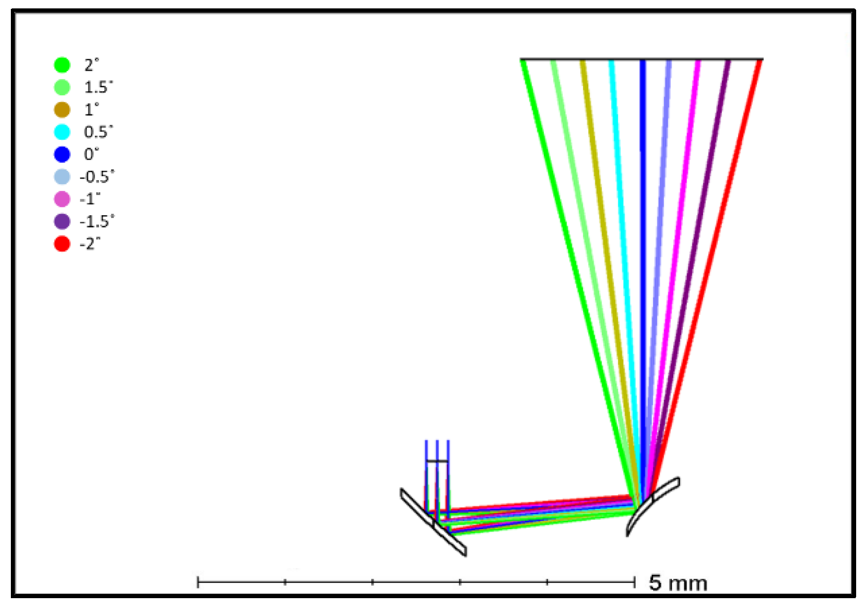
In order to make the two mirrors sit on the same substrate so that the alignment procedure can be eliminated, the L shape arrangement of the two mirrors was exploited, as shown in Figure 2, where the laser beam comes in from the top. The scanning angle of the incoming beam is taken as four degree, and the desired scanning angle magnification is set as seven times. The wavelength is taken as 1550 nm and the laser beam size is 0.5 mm. Due to achromatic feature of the reflective surface, the scanning optics can be used for all other wavelength, with the only concern on the difference of diffraction behavior. The incoming laser beam is assumed to be fully collimated and the diverging angle of the outgoing beam is expected to be smaller than 8 mrad.
For mirror 1 which function is to focus a collimated laser beam, the parabolic surface has been used as the basic structure. The vertex curvature R can then be expressed as Equation (1), where d is the mechanical dimension shown in Figure 3a.
The major function of mirror 2 is the magnification of scanning angle. A spherical surface is used as the starting point for the first order design. In Figure 3b, Q is the focal point of mirror 1, which has a horizontal offset u from the vertex of mirror 2. φ1 and φ2 stands for the two extreme scanning angles of incoming beam measured from the horizontal axis. With small angle approximation, the geometrical relationship expressed in Equation (2) can be obtained.
To formulate the relationship between θout and θin, the conservation of Etendue in paraxial optics has been exploited. In Figure 3b, M’Q’ is the image of MQ formed by mirror 2, and the geometrical relationship shown in Equation (3) can be obtained with small angle approximation.
Combining Equations (2) and (3), the following relationship can be obtained.
The relationship between u and u′ can then be expressed with mirror imaging formula as Equation (5).
With Equations (4) and (5) and the initial parameters listed in Table 1, the basic curvature of mirror 1 and mirror 2 becomes 4.95 mm and 0.33 mm, respectively.
The basic curvature of two mirrors is put into the commercial ray tracing program ZEMAX for further optimization with the introduction of conic constant and high order term. Multi-configuration of several incoming scanning angles with a step of 0.5 degree are taken for optimization as listed in Table 2, and the target with high weighting is the desired corresponding direction of the outgoing beam and the diverging angle of the beam being smaller than 8 mrad. The data of the curves for two mirrors and the system layout with a light path of all chosen scanning angles in optimization are listed in Table 3 and shown in Figure 4. Both desired targets can be met for all chosen scanning angles, and the result should be valid for all wavelengths in terms of geometrical optics because the reflective surface is achromatic. However, by checking the focal spot size on mirror 2, it indicates a diffraction limit situation, at least for 1550 nm, i.e., the geometrical focal spot size is smaller than the Airy disc. This means that the area of the laser beam cover on mirror 2 is larger than what is evaluated with geometrical optics. As a consequence, the diverging angle of the outgoing beam predicted with geometrical optics is not correct.
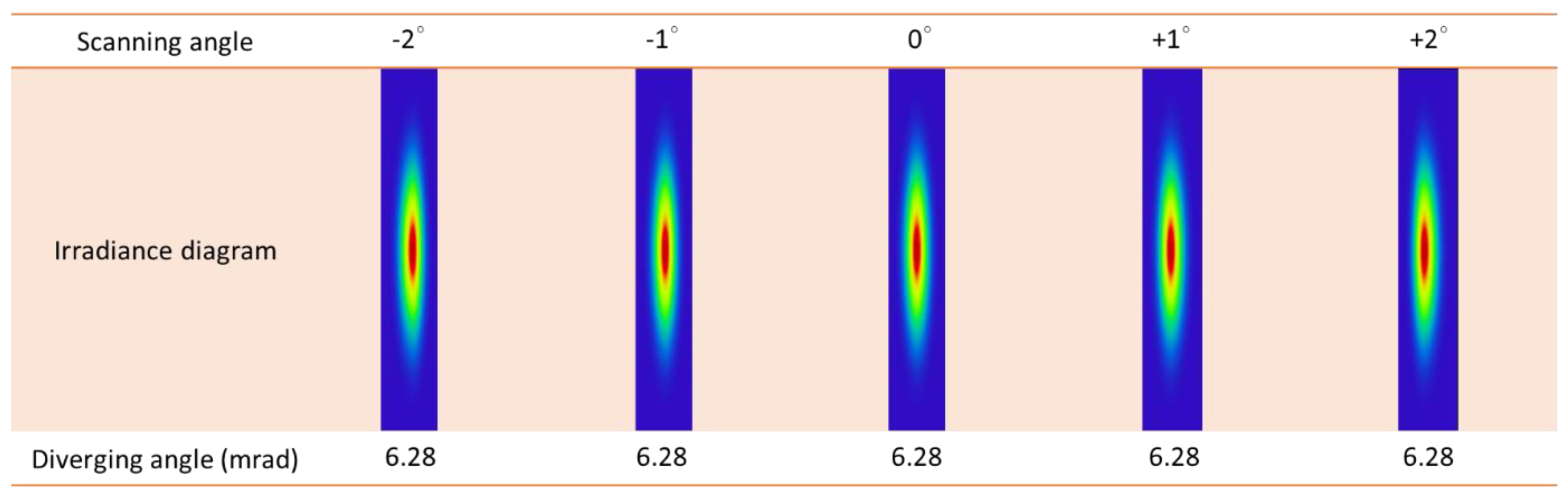
The function of physical optics in ZEMAX is then taken in order to analyze the performance of the outgoing beam, especially in a diverging angle. Figure 5 shows the irradiance of the beam at the position of 2000 mm away for all chosen scanning angles and its corresponding diverging angle. The diverging angle in the program is the subtended angle of two asymptotes of the laser beam, and the result indicates that all scanning angles meet the criteria of being smaller than 8 mrad. The beam size in the vertical direction is in the original size of 0.5 mm.
Figure 6 shows similar irradiance diagram and corresponding diverging angle for the case of wavelength at 625 nm. As the airy disc is smaller for shorter wavelengths, the diverging angle of the outgoing beam with 625 nm becomes smaller than that of the corresponding case with 1550 nm.
With the analytical result shown in Figure 5 and Figure 6, the two mirror optics with an optimized free form surface can be used for wavelengths from 625 nm to 1550 nm to meet the desired function of seven times of scanning angle magnification while keeping the diverging angle of the beam smaller than 8 mrad at all scanning angles.
4. Prototype and Evaluation
The prototype of the optics is made with precision diamond turning on an aluminum substrate as shown in Figure 7. The size marked on the figure indicates its compactness.
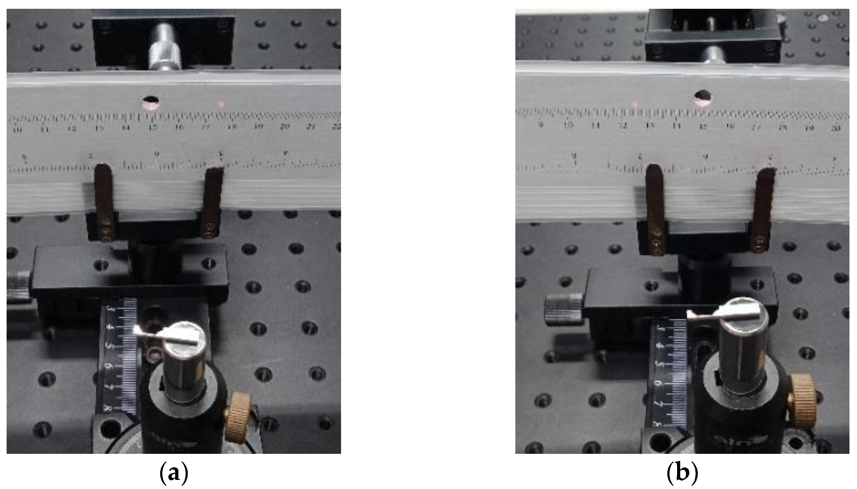
For evaluating the performance of the two mirror optics, a diode laser with a wavelength of 625 nm has been used. Figure 8 shows the setup for experiment. The laser beam is collimated and reduced to the size of 0.5 mm before passing through a pinhole on the screen to hit on the first mirror. There is a ruler on the screen to measure the position of the reflected outgoing beam as shown in Figure 9. The rotation of the two mirror optics is used to replace the scanning of the laser beam. To check the magnification of the scanning angle, the device is rotated from +2° to −2°, and the laser spot position on the ruler, associated with geometry calculation, indicates that the angular magnification is 7.
For evaluating the diverging angle, a flat mirror is used to direct the outgoing beam from the device so that the spot size at two extreme scanning angles, i.e., ±2°, can measured at the propagation distance of 200 mm and 2000 mm, as shown in Figure 10a. The result is shown in Figure 10b. By using 1/e of peak intensity as the measure for laser beam size and geometrical calculation, the diverging angle of the outgoing laser beam at the scanning angle of +2° and −2° are 2.4 mrad and 2.1 mrad, respectively. Both meet the desired performance.
5. Discussion
The proposed two mirror optics for scanning angle magnification has a fundamentally different light path from that of the afocal system which most prior arts adopt [21]. The second mirror is located at or close to the focal plane of the first mirror. The function of scanning angle magnification is purely performed by the second mirror, whereas the function of the first mirror is to compensate the diverging angle associated with the scanning angle magnification on the second mirror to make the final outgoing laser beam collimated. The amount of the associated diverging angle on the second mirror depends on the focal spot size on it and its curvature profile, and the amount of compensation from the first mirror depends on its curvature profile and f-number. Therefore, the curvature profile of both mirrors becomes the major parameters for designing the whole system to meet the required scanning angle magnification and outgoing diverging angle. Because the associated diverging angle on the second mirror depends on the focal spot size on it, the spot size needs to be examined correctly for evaluating the associated diverging angle. It is found in geometrical ray tracing that the focal spot is in the case of the diffraction limit, and therefore the whole analysis turns to the methodology based on physical optics. Once the analysis is based on physical optics, the prediction of diverging angle needs to follow, and the rule becomes that the smaller the focal beam waist, the larger the diverging angle. This result is just opposite to that from the analysis based on geometrical optics. As a consequence, the methodology to be chosen for analyzing the focal spot size and the diverging angle depends on whether it is a diffraction limit or an aberration dominated system. For a small diverging angle, a high precision of the fabrication process is required, or it can easily turn into an aberration dominated system with small deviation on the curvature. Moreover, 8 mrad of diverging angle has been chosen for this case to reduce the disruption from the fabrication error on the curvature profile so that the working concept of the proposed optics can be verified on the prototype based on physical optics. For the cases where a larger scanning angle magnification and a smaller diverging angle are required, the same concept can be applied but the support of high precision fabrication is essential.
6. Conclusions
A two mirror optical module with an approximate size of 8 mm × 2 mm has been proposed and prototyped. Both analysis and evaluation show that the module can magnify the scanning angle of an incoming laser beam up to seven times while keeping the diverging angle of the outgoing beam smaller than 8 mrad. As both mirrors can be freeform surfaces, there are sufficient degrees of freedom to deal with different requirements, such as magnification ratio of canning angle, diverging/converging angle of incoming, and outgoing laser beam. In addition, a similar concept can be expanded to two-dimensional scanning cases.
Author Contributions
Conceptualization, C.-H.C.; methodology, C.-T.M.; software, C.-T.M. and P.-C.C.; validation, C.-T.M.; formal analysis, C.-T.M.; investigation, C.-T.M.; resources, P.-C.C.; data curation, C.-T.M.; writing—original draft preparation, C.-T.M.; writing—review and editing, C.-H.C.; visualization, C.-T.M. and P.-C.C.; supervision, C.-H.C.; project administration, C.-H.C.; funding acquisition, C.-H.C. All authors have read and agreed to the published version of the manuscript.
Funding
This research received no external funding.
Institutional Review Board Statement
Not applicable.
Informed Consent Statement
Not applicable.
Data Availability Statement
The data presented in this study are available on request from the corresponding author. The data are not publicly available due to privacy.
Acknowledgments
The authors would like to thank San-Liang Lee of the National Taiwan University of Science and Technology for the consultancy on the phase array laser.
Conflicts of Interest
The authors declare no conflict of interest.
References
- McManamon, P.F. LiDAR Technologies and Systems; SPIE Digital Library: Bellingham, WA, USA, 2019. [Google Scholar]
- Mehendale, N.; Neoge, S. Review on Lidar Technology. SSRN 2020. [Google Scholar] [CrossRef]
- Comerón, A.; Muñoz-Porcar, C.; Rocadenbosch, F.; Rodríguez-Gómez, A.; Sicard, M. Current Research in Lidar Technology Used for the Remote Sensing of Atmospheric Aerosols. Sensors 2017, 17, 1450. [Google Scholar] [CrossRef] [PubMed] [Green Version]
- Paul, A.; Chauhan, R.; Srivastava, R.; Baruah, M. Advanced Driver Assistance Systems. SAE Tech. Pap. 2016, 28, 0223. [Google Scholar]
- Jiménez, F.; Naranjo, J.E.; Anaya, J.J.; García, F.; Ponz, A.; Armingol, J.M. Advanced Driver Assistance System for Road Environments to Improve Safety and Efficiency. Transp. Res. Procedia 2016, 14, 2245–2254. [Google Scholar] [CrossRef] [Green Version]
- Lu, M.; Wevers, K.; van der Heijden, R. Technical feasibility of advanced driver assistance systems (ADAS) for road traffic safety. Transp. Plan. Technol. 2005, 28, 167–187. [Google Scholar] [CrossRef] [Green Version]
- Kumar, A.M.; Simon, P. Review of lane detection and tracking algorithms in advanced driver assistance system. Int. J. Comput. Sci. Inf. Technol. 2015, 7, 65–78. [Google Scholar] [CrossRef]
- Royo, S.; Ballesta-Garcia, M. An Overview of Lidar Imaging Systems for Autonomous Vehicles. Appl. Sci. 2019, 9, 4093. [Google Scholar] [CrossRef] [Green Version]
- Woodside Capital Partners & Yole Développement. Automotive LiDAR Market Report; OIDA Publications & Reports; Optical Society of America: Washington, DC, USA, 2018. [Google Scholar]
- Schoonover, D. The Driverless Car Is Closer Than You Think—And I Can’t Wait; Forbes: Randall Lane, NJ, USA, 2019. [Google Scholar]
- Schwarz, B. Mapping the world in 3D. Nat. Photon 2010, 4, 429–430. [Google Scholar] [CrossRef]
- Raj, T.; Hashim, F.H.; Huddin, A.B.; Ibrahim, M.F.; Hussain, A. A Survey on LiDAR Scanning Mechanisms. Electronics 2020, 9, 741. [Google Scholar] [CrossRef]
- Heck, M.J.R. Highly integrated optical phased arrays: Photonic integrated circuits for optical beam shaping and beam steering. Nanophotonics 2017, 6, 93–107. [Google Scholar] [CrossRef]
- Abediasl, H.; Hashemi, H. Monolithic optical phased-array transceiver in a standard SOI CMOS process. Opt. Express 2015, 23, 6509–6519. [Google Scholar] [CrossRef] [PubMed]
- Poulton, C.V.; Yaacobi, A.; Cole, D.B.; Byrd, M.J.; Raval, M.; Vermeulen, D.; Watts, M.R. Coherent solid-state LIDAR with silicon photonic optical phased arrays. Opt. Lett. 2017, 42, 4091–4094. [Google Scholar] [CrossRef] [PubMed]
- Hsu, C.-P.; Li, B.; Solano-Rivas, B.; Gohil, A.R.; Chan, P.H.; Moore, A.D.; Donzella, V. A Review and Perspective on Optical Phased Array for Automotive LiDAR. IEEE J. Sel. Top. Quantum Electron. 2021, 27, 1–16. [Google Scholar] [CrossRef]
- Sun, J.; Timurdogan, E.; Yaacobi, A.; Hosseini, E.S.; Watts, M.R. Large-scale nanophotonic phased array. Nature 2013, 493, 195–199. [Google Scholar] [CrossRef]
- Guo, W.; Binetti, P.R.; Althouse, C.; Mašanović, M.L.; Ambrosius, H.P.; Johansson, L.A.; Coldren, L.A. Two-Dimensional Optical Beam Steering with InP-Based Photonic Integrated Circuits. IEEE J. Sel. Top. Quantum Electron. 2013, 19, 6100212. [Google Scholar]
- Hulme, J.C.; Doylend, J.K.; Heck, M.J.R.; Peters, J.D.; Davenport, M.L.; Bovington, J.T.; Coldren, L.A.; Bowers, J.E. Fully integrated hybrid silicon free-space beam steering source with 32-channel phased array. SPIE Proc. 2014, 8989, 898907–898921. [Google Scholar]
- Demersseman, B.; Hansson, P.; Hällstig, E. Detection system with reflection member and offset detection array. US20190101645A1, 4 April 2019. [Google Scholar]
- Lee, X.; Wang, C. Optical design for uniform scanning in MEMS-based 3D imaging lidar. Appl. Opt. 2015, 54, 2219–2223. [Google Scholar] [CrossRef] [PubMed]
- Lee, X.; Wang, C.; Luo, Z.; Li, S. Optical design of a new folding scanning system in MEMS-based lidar. Opt. Laser Technol. 2020, 125, 106013–106020. [Google Scholar] [CrossRef]
Figure 1.
Schematic diagram of scanning angle magnification with two reflective surfaces.

Figure 2.
Schematic diagram of the L shape arrangement of the two mirror optics.

Figure 3.
Schematic diagram of for determining the basic curvature of two mirrors. (a) Parabolic mirror, (b) spherical mirror.
Figure 3.
Schematic diagram of for determining the basic curvature of two mirrors. (a) Parabolic mirror, (b) spherical mirror.

Figure 4.
System layout with light path of all chosen scanning angles in optimization.

Figure 5.
Irradiance diagram of the outgoing laser beam at 2000 mm and the corresponding diverging angle for all chosen scanning angles (λ = 1550 nm).
Figure 5.
Irradiance diagram of the outgoing laser beam at 2000 mm and the corresponding diverging angle for all chosen scanning angles (λ = 1550 nm).

Figure 6.
Irradiance diagram of the outgoing laser beam at 2000 mm and corresponding diverging angle for all chosen scanning angles (λ = 625 nm).
Figure 6.
Irradiance diagram of the outgoing laser beam at 2000 mm and corresponding diverging angle for all chosen scanning angles (λ = 625 nm).

Figure 7.
Prototype of the two mirror optics for beam scanning angle magnification.

Figure 8.
Experimental setup.

Figure 9.
Reflected laser spot on the ruler. (a) +2°, (b) −2°.

Figure 10.
Irradiance of outgoing laser beam at the distance of 200 mm and 2000 mm for the scanning angle of +2° and −2°. (a) experiment setup, (b) irradiance.
Figure 10.
Irradiance of outgoing laser beam at the distance of 200 mm and 2000 mm for the scanning angle of +2° and −2°. (a) experiment setup, (b) irradiance.


Table 1.
Initial design parameters.
| d | θin | u |
|---|---|---|
| 3.5 mm | 4 | 1 mm |
Table 2.
Optimized multi-configuration of the optical system.
| Configuration No. | 1 | 2 | 3 | 4 | 5 | 6 | 7 | 8 | 9 |
|---|---|---|---|---|---|---|---|---|---|
| Input angle (°) | −2 | −1.5 | −1 | −0.5 | 0 | 0.5 | 1 | 1.5 | 2 |
| Scanning angle (°) | −14 | −10.5 | −7 | −3.5 | 0 | 3.5 | 7 | 10.5 | 14 |
Table 3.
Design parameters of the optical system.
| Mirror No. | Surface Type | Radius | Conic | X Radius | X Conic |
|---|---|---|---|---|---|
| 1 | Biconic Zernike | −4.781 | −1 | −55 | −1 |
| 2 | Biconic Zernike | −0.633 | −0.357 | −104.397 | −264.4 |
Publisher’s Note: MDPI stays neutral with regard to jurisdictional claims in published maps and institutional affiliations. |
© 2022 by the authors. Licensee MDPI, Basel, Switzerland. This article is an open access article distributed under the terms and conditions of the Creative Commons Attribution (CC BY) license (https://creativecommons.org/licenses/by/4.0/).
Share and Cite
MDPI and ACS Style
Mu, C.-T.; Chang, P.-C.; Chen, C.-H. Scanning Angle Magnification with Compact Reflective Optics for Light Detection and Ranging. Photonics 2022, 9, 59. https://0-doi-org.brum.beds.ac.uk/10.3390/photonics9020059
AMA Style
Mu C-T, Chang P-C, Chen C-H. Scanning Angle Magnification with Compact Reflective Optics for Light Detection and Ranging. Photonics. 2022; 9(2):59. https://0-doi-org.brum.beds.ac.uk/10.3390/photonics9020059
Chicago/Turabian StyleMu, Cheng-Ta, Po-Cheng Chang, and Cheng-Huan Chen. 2022. "Scanning Angle Magnification with Compact Reflective Optics for Light Detection and Ranging" Photonics 9, no. 2: 59. https://0-doi-org.brum.beds.ac.uk/10.3390/photonics9020059
Note that from the first issue of 2016, this journal uses article numbers instead of page numbers. See further details here.