
A Fuzzy Logic-Based Algorithm to Solve the Slot Planning Problem in Container Vessels


1
Department of Industrial and Manufacturing Engineering, Egypt-Japan University of Science and Technology (E-JUST), Alexandria 21934, Egypt
2
Production Engineering Department, Faculty of Engineering, Alexandria University, Alexandria 21544, Egypt
*
Author to whom correspondence should be addressed.
Logistics 2021, 5(4), 67; https://0-doi-org.brum.beds.ac.uk/10.3390/logistics5040067
Submission received: 24 July 2021
/
Revised: 16 August 2021
/
Accepted: 23 August 2021
/
Published: 28 September 2021
(This article belongs to the Special Issue Optimization and Management in Maritime Transportation)
Abstract
:Background: The slot planning problem is a container allocation problem within a certain location on a vessel. It is considered a sub-problem of a successful decomposition approach for the container vessel stowage planning problem. This decision has a direct effect on container handling operations and the vessel berthing time, which are key indicators for the container terminal efficiency. Methods: In this paper, an approach combining a rule-based fuzzy logic algorithm with a rule-based search algorithm is developed to solve the slot planning problem. The rules in the proposed fuzzy logic algorithm aim at improving the objective function and minimizing/eliminating constraint violation. Results: The computational results of 236 slot planning instances illustrate the efficiency and effectiveness of the proposed algorithm. Conclusions: The results show that the proposed approach is fast and can produce optimal or near-optimal solutions for a comprehensive industrial set of instances.
1. Introduction
Goods trading has globally increased after the development of standard containers in 1956 by Malcolm McLean [1]. A standard container is a metallic box that can withstand both substantial external forces and high vertical compression stress. Therefore, it allows the formation of high stacks of containers [2]. Containerized shipping facilitated size expansion of vessels, hence expanding the goods transportation worldwide across countries [3].
According to the statistics of the United Nations Conference on Trade and Development, the world’s global container throughput was 752 million TEUs (Twenty-foot Equivalent Units) in 2017, which displays a 34% growth from 560 million TEUs in 2010 [4]. Whereas in 2019 the container throughput reached approximately 802 million TEUs, with an increase of 2.3 percent compared to 2018 [5]. According to Container Trade Statistics (CTS), the COVID-19 pandemic negatively impacted global trade, yet container throughput increased by 6.9% in September 2020 when compared to that of September 2019.
The continuous increase in the global trade volumes raises the demand for a cost-effective mode of transportation, which consequently, presents a dilemma for shipping companies. This situation has led to the deployment of large container vessels, which can transport up to 20,000 TEUs [6]. However, with larger more economic vessels, the decision to stow a very large number of containers becomes a real challenge.
The container vessel transports containers employing few crew members and travels a fixed cyclic route of ports. In the port, quay cranes are used for loading and unloading the containers to and from the vessel. The number of needed quay crane movements increases with larger container vessels. Consequently, the time required for vessels to stay at each port (i.e., berthing time) is increased, and the turnover of the container vessel is consequently decreased [2,7].
The key performance indicator of the container vessel is the fast turnover that will eventually increase the profit to both ports and shipping companies [1,8]. Additionally, the probability of vessels reaching their destinations at lower sailing speeds is increased, with lesser berthing times, translating into lesser fuel consumption and CO2 emissions [9].
Since the operating costs for shipping companies are partially determined by the port’s fees, it is significant to effectively manage the intricate activities in the port to reduce the vessel’s turnaround time and handling charges [10]. The effective arrangement of containers on board vessels (i.e., stowage planning) affects the berthing time, the containers’ handling operations, the vessel’s stability during sailing, and the handling operations. Hence, an effective stowage plan is a key to reach higher productivity and ensuring the safety of the vessels [11,12,13].
Container stowage planning is defined as the problem of assigning a set of “C” containers of diverse types to a set of “L” dedicated storage spaces within the vessel. This is an NP-hard problem [14,15]. Several structural and operational constraints must be ensured by this assignment. These constraints are related to both the vessel and containers to achieve different objectives. One of these objectives is minimizing the loading time [16].
In the past, stowage plans were manually engendered by stowage coordinators. However, in recent years, increasing interest is directed towards finding effective optimization algorithms to help large vessels stowage coordinators, who are striving for lower costs through shortening berthing times, continuous changes in the load lists, among others. Hence, the objective of the shipping companies, in this case, is to find an optimum solution in a reasonable time despite the increase in the complexity of the problem. In practice, producing effective stowage plans is complicated owing to the following causes:
- Thousands of loading/unloading moves are required for large container vessels [17].
- The proposed algorithms should be fast with a runtime of less than 10 min, to cope with the last-minute load list changes. This is a practical requirement from the shipping companies to evaluate different forecast scenarios for the load list for the upcoming ports in the vessel’s route [7].
- The stowage coordinators have limited time to produce the stowage plans [18].
- The complex interactions between the low-level stacking rules, the high-level stress limits and the stability requirements of the vessel impose a trade-off between minimizing the overstowage and making use of the span of the quay cranes. In the meantime, overstowage is considered as container blockage that can lead to unnecessary additional movements of the containers during the loading/unloading operations [18].
The stowage planning problem is a complex problem, consequently, in this work, a solution approach with an embedded hierarchical decomposition of the problem is introduced. Generally, the proposed approach mimics the work process of human stowage coordinators, thus, making the problem scalable and producing satisfactory results of the real instances in a reasonable time [9,17,19,20,21].
There are explicitly two techniques adopted for the solution of this problem [22]. These two solution approaches consider the problem solution as follows:
- Single-phase approaches [23]:This approach represents the structure of the vessel as a set of slots and consists of formulating a model to describe the whole stowage problem at once to minimize the overstowage. Most of these approaches have a common denominator, is to sacrifice model accuracy (e.g., doesn’t consider the vessel’s stability, or only a very simplified representation is used such as weight distribution) to achieve scalability.In this case the input data consists of the overall list of Containers-To-Load (CTLAll Vessel) onto the vessel (presented in a transportation matrix: the number of containers loaded and unloaded in each port in the vessel’s route). In addition to vessel characteristics (mostly treating the vessel as rectangular bays rather than the true vessel’s configuration). Due to the problem simplification, this approach cannot guarantee obtaining optimal solution for application requirement if used on commercial sized vessel in a reasonable time [24]
- This approach classifies the constraints and objectives into high-level and low-level
- High-level constraints and objectives:These include vessel stability and balancing requirement that is essential for seaworthiness [2], (including the draft, trim, metacentric height (GM), and stress moments such as shear, bending and torsion, in addition to satisfying the weight and volume capacity limits as well as capacity limits of the different container types of the bays) [18]. The common objectives are the minimization of hatch overstowage (minimize the number of containers on deck that need to be removed in order to gain access to containers below deck) and crane make-span.
- Low-level constraints and objectives:These are mainly the shipping line stacking rules that concern the way each container is loaded into a position on the vessel. These rules include but not limited to that the weight and height capacities are satisfied, and that reefers (refrigerated containers) are assigned to positions with a power supply. The objective reflects the rules of thumb of stowage coordinators (explained later) to obtain stowage plans that are robust to fluctuations in the forecasted demands [18].
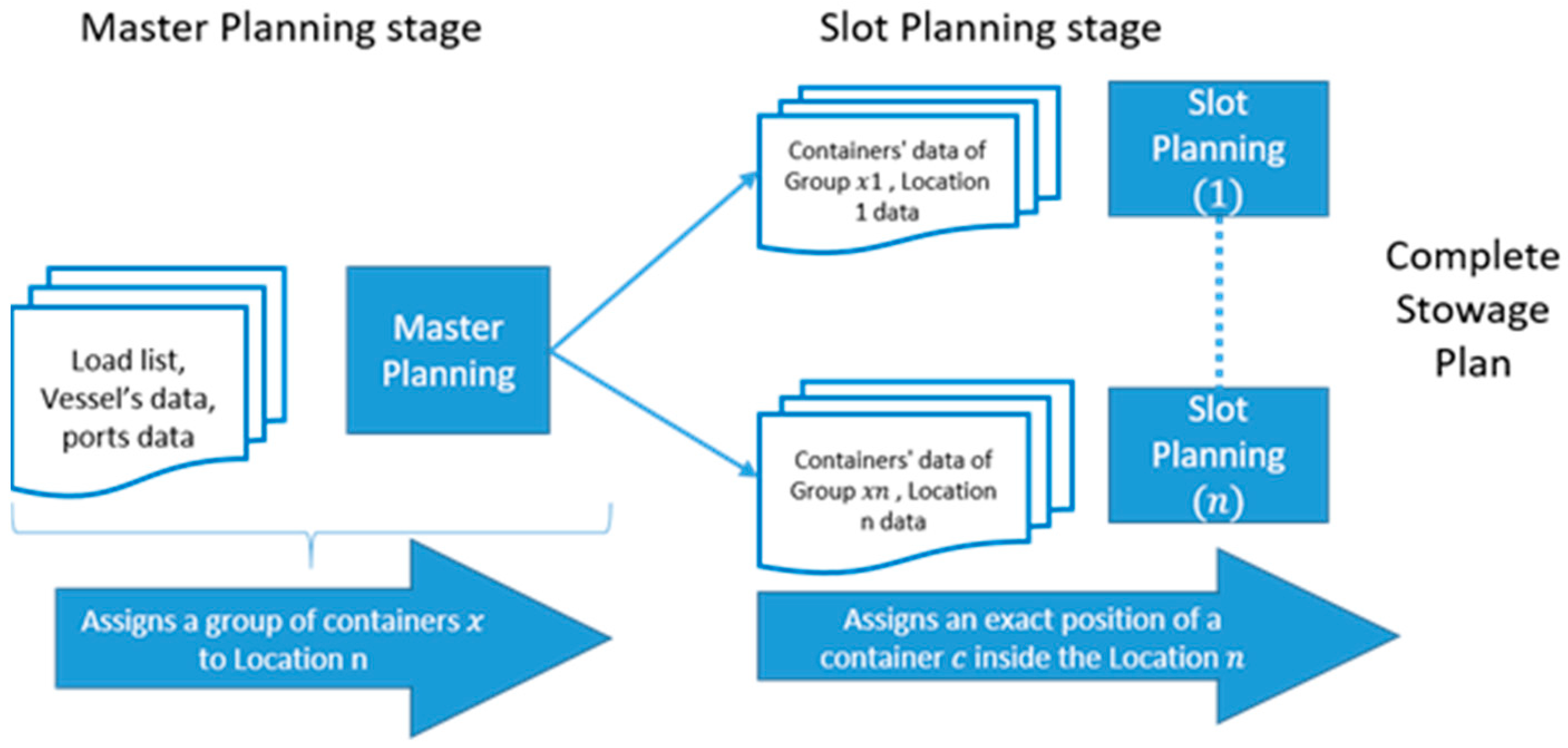
This technique, shown in Figure 1, subdivides the stowage planning problem into two consecutive phases the multi-port master planning phase or class-based stowage planning and the slot planning phase. The vessel is subdivided into several “Locations” (i.e., bay sections). In this case, the input data consisting of CTLAll Vessel (a list of containers to be loaded at the current port and a forecast for the later ones), in addition to vessel and ports characteristics. In this phase (Master Planning Phase), only high-level constraints and objectives are implemented to generate a master layout plan. The output of this phase is an assignment of all groups of containers to specific locations in the vessel.
The output of this phase is the input of the slot planning phase. The CTLAll Vessel is consequently subdivided into (n) lists (Containers-To-Load list for each location) (CTL(1) to CTL(n)) each of which would be required to undergo a second phase of optimization (Phase 2) with a Slot Planning Algorithm (SPA) to satisfy the low-level constraints and objectives. This approach is the most successful in terms of model accuracy and scalability [25]. This phase is can be either performed by the shipping line or the terminal’s operators to optimize the loading sequencing [2].
As mentioned earlier, there is an increasing practical demand from shipping companies that the whole stowage plan is generated fast enough within less than 10 min [2]. Putting into consideration that there are about 100 locations [18] in a large container vessel and that the first phase is time-consuming, result in the fact that each independent slot planning problem needs to be solved within 1 s [18]. This imposes a practical time constraint for this problem.
Slot planning is considered an NP-hard problem because it deals with hundreds of containers, which makes solving the problem a hard task [7]. The emphasis of this study is the slot planning phase (second phase of the two-phase technique) while considering the below deck locations only. The problem is denoted as the Container Stowage Problem for Below Deck Locations (CSPBDL). Additionally, it introduces an algorithm based on a structured rule-based search to solve the problem.
The detailed stowage plan has the objective of finding a specific cell/slot for each 40′/20′ container within each location, which was the output of the master plan while considering the stack constraints. To generate a valid stowage plan, these constraints must be fulfilled. The containers in the problem are of different types and their characteristics are as follows:
- The size; ISO containers are normally 8′ wide, height (8′6′′ and 9′6′′), length (20′, 40′ and 45′);
- The weight;
- The Discharge Port or Port Of Destination (POD) (i.e., where it would be unloaded);
- Whether the container is refrigerated and needs an electric power supply (i.e., reefer container); and
- Other special containers must be placed according to a complex set of separation rules, for example, containers with dangerous goods (IMO containers) and pallet-wide containers which are slightly wider.
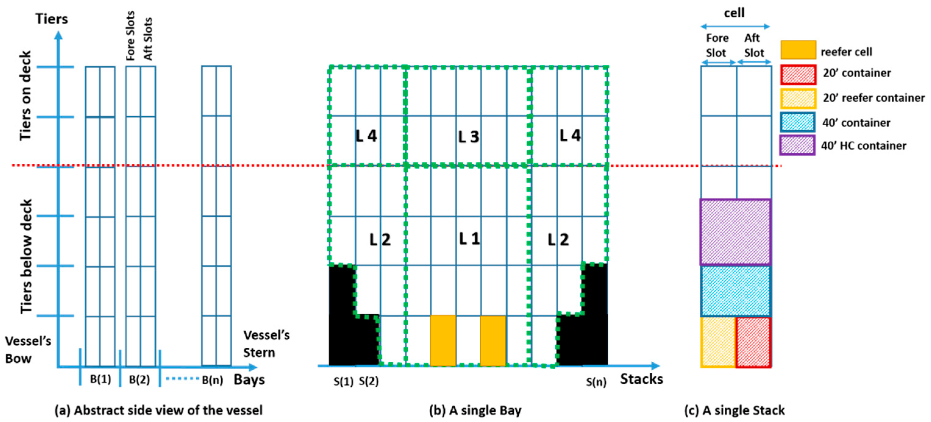
Figure 2 illustrates the different terminologies pertaining to the slot planning problem. (a) is the side view of the abstract arrangement of the bays on the vessel separated into tiers on deck and below deck by a line representing the hatch cover. (b) is a single bay divided into 4 different locations (L1, L2, L3, L4) showing the available reefer cells. (c) is a single stack with a 20′ container occupying a slot and 40′ occupying a cell.
The capacity of a container vessel is defined in TEU (twenty feet equivalent unit). The cargo space of a container vessel is divided into a number of subsequent bays, as shown in Figure 2a. In the figure, there is a hatch cover (represented by a red dotted line). This is a flat, leak-proof structure that prevents the vessel from taking in water. This cover divides the vessel (i.e., each bay) into on-deck and below-deck areas.
Each bay is split into several locations. A location is a set of vertical stacks and horizontal tiers that could be over or under the deck as shown in Figure 2b, the bay is divided into four Locations (L1, L2, L3, and L4), where a group of containers may be assigned for allocation. Each stack allows for the vertical stacking of containers. Figure 2b also illustrates the existence of blocked slots at the bottom of the vessel, represented in black, where no containers can be allocated because of the layout of the vessel.
A cell results from the intersection between the horizontal tier and the vertical stack. It can either hold a single 40′ container or two 20′ containers as shown in Figure 2c. A cell consists of a fore-slot (bow-side position) and an aft-slot (stern-side position). Some of these cells/slots have access to power plugs to provide electricity to reefer containers. They are termed ‘reefer cells/slots’ as shown in Figure 2b. Finally, each container stack has weight and height limit restrictions.
The problem of assigning a set of 20′ and 40′ containers to a set of under deck cells/slots is the problem under consideration in this research. These containers could be either high cube containers (9′6′′ high) or standard (8′6′′ high), both being either reefer or not. One important remark that must be considered is that the loading and unloading of the containers are performed by quay cranes. This implies that they can only access the top container of a stack first.
The following constraints and objectives define the Container Stowage Planning Problem for an Under Deck Location (CSPUDL) as stated in [7]:
- The assigned containers to a certain stack must be stacked on top of each other (i.e., no container can physically hang in the air).
- A cell must be either empty or fully loaded and should satisfy the length constraints (i.e., the two slots are occupied by two 20′ containers or one 40′ container ==> Hence, the number of 20′ containers must be even).
- 20′ containers are forbidden to be stowed above a 40′ container.
- A 20′/40′ reefer container must be placed in a slot/cell that has access to a power plug, respectively.
- The sum of the weights and heights of the allocated containers must conform to the stack weight and height limits.
- Already existing containers cannot be reallocated.
The objective function is presented in Equation (1) for the necessary sets and variables depicted in Table 1
The first objective primarily targets the economic aspects of a stowage plan, while the other objectives are considered as the rules of thumb of the shipping industry. Better stowage plans are provided in downstream ports of the vessel’s voyage owing to:
- using fewer stacks and fewer PODs within a stack in the current port
- increasing the available space in a location
- reducing the possibility of overstowage in the downstream ports
- Increasing the number of reefer containers to be loaded in the downstream ports.
In order to evaluate the quality of the generated valid solutions that satisfy the above-mentioned constraints, a set of objectives are defined as follows, the values of the different penalties are defined by Delgado et al. [7] and Pacino and Jensen [18]:
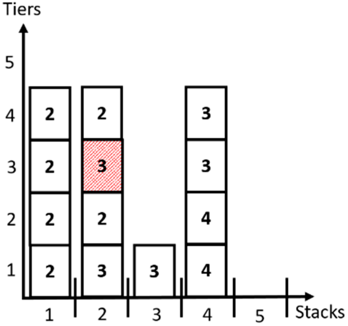
- Overstowage is minimized. An over-stowed container is a container that has a POD further than any of the containers, which are located beneath it as shown in the second stack in Figure 3. A penalty of POS = 100 units is paid for each over-stowed container.
- Having containers of different PODs within the same stack is minimized. A penalty of PDP = 20 units is paid for each POD that is included within a stack. For example, in Figure 3, the total penalty is 120 for the four stacks is added to the objective function.
- The number of non-empty stacks (i.e., used stack) is minimized. A penalty of PS = 10 units is paid if there is at least one container located in a stack. For example, in Figure 3, the total penalty is 40 for the four occupied stacks added to the objective function.
- Locating a non-reefer container in a reefer cell is minimized. A penalty of PR = 5 units is paid for each reefer slot that is occupied with a non-reefer container is added to the objective function.
2. Literature Review
The stowage planning problem is a variation from the container premarshalling and the container stacking problems [26,27]. It is tackled in the literature through two different types of approaches: the single-phase approach and the decomposition approach. The single-phase approach deals with the whole vessel at once considering the container vessel having a set of available slots and assigning a specific container to a specific cell/slot. The latter approach decomposes the problem into two successive phases: the multi-port master planning phase and the slot planning phase.
2.1. The Single-Phase Approach
The single-bay stowage planning problem was solved in 1998 by Avriel et al. [28]. The authors developed a binary linear programming model, and a heuristic procedure called the Suspensory Heuristic (SH) to minimize the number of onboard shifts (to remove over-stowing containers) at each container terminal. This problem assumes that the vessel is one large bay. Later, Dubrovsky et al. [29] presented a Genetic Algorithm (GA) approach for the solution of the same problem. The results of the GA approach were similar to those obtained by the (SH). Furthermore, a state-of-the-art heuristic solution approach was proposed by Ding and Chou [30] that improved the results of the (SH).
Rashed et al. [31] proposed a rule-based greedy algorithm to solve the same problem, the algorithm was simple and effective when it was compared against the performance of the heuristic of Ding and Chou [30] in one of the instances. Roberti and Pacino [32] developed a decomposition method to solve the same problem to find the optimal container stowage plans and it outperformed the proposed methods in [28,30].
Azevedo et al. [33] considered the container vessel to be three dimensional. They used beam search heuristics and representation by rules to minimize the number of shifts and the sum of the vessel’s instability measures. The authors then extended the work in [23,34,35,36]. In [23,35] they used the representation by rules with a genetic algorithm solution approach and a participatory learning system. In [34] the representation by rules combined with three meta-heuristics: simulated annealing, beam search and GA solution were used to solve the problem. Finally, in [36] the stowage planning problem was integrated with the scheduling of the quay cranes problem and solved using representation by rules in addition to GAs and simulation. Lee et al. [37,38] presented a new solution approach based on the constraint test ordering optimization under the theme of the automated stowage planning problem.
2.2. The Decomposition Approach
This approach was introduced by Wilson and Roach in 1999 [39]. They solved both phases and considered different types of containers. The first phase had multiple objectives and was solved by branch and bound technique considering the vessel’s stability and segregation rules. Whereas the second phase was solved by packing heuristics and Tabu search algorithms to minimize multiple objectives. The authors then introduced a simple mathematical formulation for both phases [17].
Kang and Kim [40] used a similar decomposition approach as [17] but they considered only 40′ containers. The authors presented a mathematical formulation for the first phase and solved it by a “greedy heuristic” based on the transportation simplex method. The second phase was solved by a tree search method. The overall objective was to minimize the time spent at container terminals while considering the vessel’s stability and stacking rules.
In 2011, Pacino et al. [9] tackled both phases. In the first phase, they minimized the hatch cover overstowage and the quay crane make-span, while considering the vessel’s stability constraints and excluding the bending moments and ballast water. The authors presented and solved an IP model for the problem. Alternatively, the second phase was solved by a combination of constraint programming and local search to satisfy multiple objectives. If no feasible solution was found, the local search rolls out containers (removing the containers from the solution).
Generating a stowage plan from the terminal point of view was approached by Ambrosino et al. [20]. They used a three-step heuristic including a Tabu search method to minimize the loading time. The proposed solution approach had some difficulties with large vessels [20]. The authors improved the solutions by using constructive loading heuristic and ant-colony optimization in [21]. Ambrosino and Sciomachen [19] addressed the stowage of hazardous containers that must follow certain rules and solved the problem using bin-packing heuristics.
The following papers solved only the master planning subproblem or the slot planning subproblem (first or the second phase, respectively) of the decomposition approach:
2.2.1. The Master Planning Phase
The Master Planning Problem (MPP) was approached by Pacino et al. [41]. They proposed an LP model with ballast tanks to generate the master plan taking into consideration the stability and stress moments constraints to minimize the change in the tank configuration. Later, Pacino proposed a large neighborhood search approach to solve the MPP [25].
Alternatively, Ambrosino et al. [42] introduced two exact Mixed Integer Programming (MIP) models for the problem while considering the stability constraints to minimize the vessel’s berthing time. The authors solved the problem using heuristics that are based on the solution of relaxations of models.
Ambrosino et al. extended their work in [43] to include a circular route for the vessel and different types of container (i.e., reefers and open tops) intending to minimize the weighted sum of the number of onboard shifts, and quay crane unbalance. The problem was formulated as a mathematical model. After that, the authors extended the solution approach in [44] and introduced a new Mixed Integer Programming (MIP) based heuristic to solve the model.
2.2.2. The Slot Planning Phase
The Slot Planning Problem (SPP) for under deck locations has been approached [7,18,45,46,47]. The objective function used in these papers was to minimize a scalar objective function including four components: overstowage; stacks used; avoiding having multiple destinations in the same stack; and having a non-reefer container placed in a reefer slot to satisfy the stacking rules. The problem solution considered 20′, 40′, high cube, and reefer containers.
Delgado et al. [45], solved the problem using constraint programming by testing a total of 17 instances and found optimal solutions for them all. Additionally, Pacino and Jensen [46] solved the same problem using a local search extended heuristic and then expanded their work to include an integer programming model. To test the solution, their instance number was increased to 133 approaches and their results were as follows: the average run time was 0.18 s for the tested instances whereas 86% of the instances reached the optimal solution [18,47].
The local search extended heuristic demonstrated a faster solution than the constraint programming in larger instances. Delgado et al. [7] delivered extensive experiments on 236 instances and provided an integer programming model to solve the problem. However, constraint programming was able to solve 90% of the instances in less than one second. It was faster than the integer programming model.
Furthermore, Parreño et al. [2] included the IMOs containers in the problem and introduced an additional objective, which is the minimization of the rolled out containers. Additionally, they developed a Greedy Randomized Adaptive Search Procedure (GRASP) algorithm and presented a novel integer programming formulation. Finally, they compared different strategies with the GRASP algorithm and equated their work against the constraint programming and constraint-based local search.
Fuzzy logic was also used in container stacking problems. Ries et al. [48] addressed the storage space allocation problem in port. The problem consisted of a 2-phase framework with a fuzzy logic system to first assign an exact position within a block space in the yard of a port to every incoming container, ensuring operational efficiency. The algorithm had good performance with respect to other algorithms proposed in the literature and the results had low variability.
Valdés-González et al. [49] introduced a fuzzy logic based intelligent system for container stacking. The system had a distinct criterion for a real-time decision for accepting or rejecting an entry request to the stacking areas of the port in Valparaiso, Chile. Rekik and Elkosantini [50] used a multi-agent system coupled with a fuzzy logic framework for the online container stacking in ports.
In summary, the number of papers related to the slot planning subproblem on its own with certain criteria that is most important to shipping companies is rather small. Although fuzzy logic usage in the container stacking problem is also scarce, it showed that its implementation provided an efficient decision tool in a wide variety of problems. Furthermore, fuzzy logic showed high-quality results in many applications; scheduling [51], sequencing [52], and routing [53] among others. Therefore, fuzzy logic is adopted here. The objectives and constraints were predefined by the underdeck locations and decided by the shipping line. The NP-hard problem is a crucial sub-problem of the stowage planning problem and therefore the time saved in reaching the optimal or near-optimal solutions of the slot planning problem helps the stowage coordinators in developing an effective complete stowage plan.
3. Proposed Methodology
The approach adopted in this research is based on a fuzzy logic system and a rule-based search algorithm. To understand the approach, a brief introduction of the fuzzy logic system is presented followed by the detailed description of the elements of the fuzzy logic specific to its application in the proposed solution approach. Finally, the explanation of the whole proposed approach to solve the slot planning problem is presented.
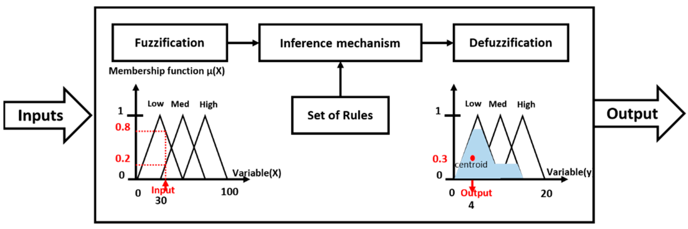
Fuzzy Logic can be considered a rule-based approach [48]. It is composed of fuzzy sets; the elements in any fuzzy set take a different degree of membership (weights) within an interval [0, 1], called the membership functions. Fuzzy logic allows the association of crisp quantitative values of the variables (e.g., weight, height) with linguistic terms (e.g., “light”, “heavy”, “high, “low”, etc…) to determine the output with the introduction of some rules. A Mamdani-type fuzzy system [54] is used in this research. A Mamdani-type fuzzy system consists of three consecutive phases: fuzzification, inference mechanism with fuzzy rule-base, and defuzzification [49], as shown in Figure 4.
The presented framework deals with the second phase of the decomposition solution approach, namely the slot planning problem. The proposed solution makes use of a fuzzy logic system implementation. The proposed fuzzy system has four input variables:
- Height eligibility ()
- Weight eligibility ()
- Number of ports eligibility ()
- Port eligibility ()
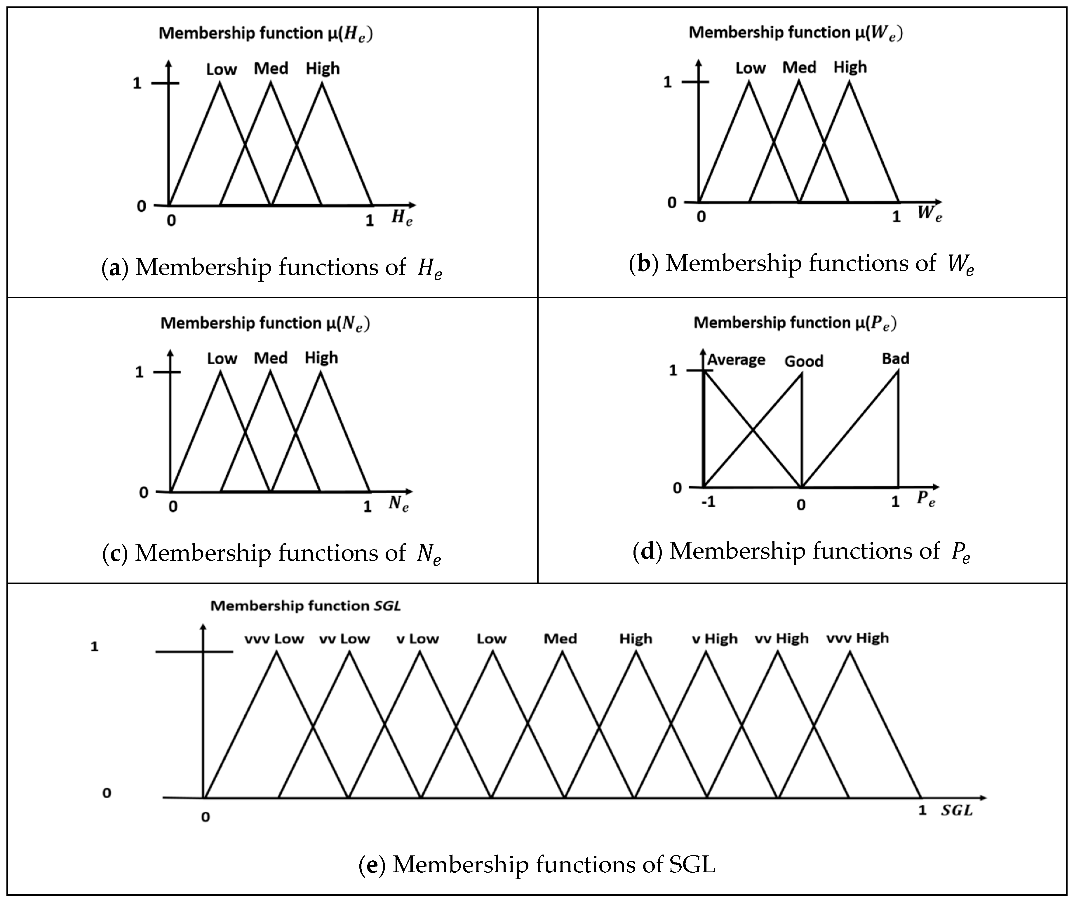
Triangular membership functions are employed as they are the most common and they best describe the situation [54,55]. The first three input variables shown in Figure 5a–c, have the same triangular membership functions. Each variable has three linguistic variables (i.e., “Low”, “Med”, and “High”). On the other hand, the membership function of is also triangular, however, it is slightly different due to the nature of the variable. It is shown in Figure 5d.
According to the proposed fuzzy logic system presented herein, each one of the four fuzzy variables has three membership functions. The total number of possible combinations would be 81 (3 × 3 × 3 × 3). This is the number of rules that are needed to implement the fuzzy inference mechanism with a rule-base. These rules are used to evaluate the corresponding output variables of the system. This output is called the Stack Goodness Level (SGL).
The SGL is used to determine how much this particular stack is conforming to fulfilling the objectives and the constraints of the problem. The sub-sets of this fuzzy output are taken to be 9 (i.e., vvvlow, vvlow, …, vvhigh, vvvhigh). These membership functions are shown in Figure 5e. As an example of the rules utilized in this system, the following is one of the 81 rules:
The remaining 80 rules take up the same form of the rule stated above. The range of the de-fuzzified values of the SGL is taken to be from 0 to 1, where 0 denotes a very bad stack adherence to the objectives and the constraints of the system. Alternatively, 1 denotes full-stack adherence to the fulfilment of the objectives and the constraints of the system.
Since this paper is only concerned with the second phase of the stowage planning problem (the slot planning problem), it takes the output of the first phase (the multi-port master planning problem) as its given input. The first phase produces a list of Containers-To-Load (CTL) for each location on the ship. In some cases, there are locations that have pre-existing containers, and their exact positions are given. These containers are grouped into a Containers-Loaded (CL) list. The elements of this list cannot be changed at any stage of the problem solution (i.e., the positions of the pre-existing containers within the location cannot change). The CL list is considered the initial condition of the slot planning problem.
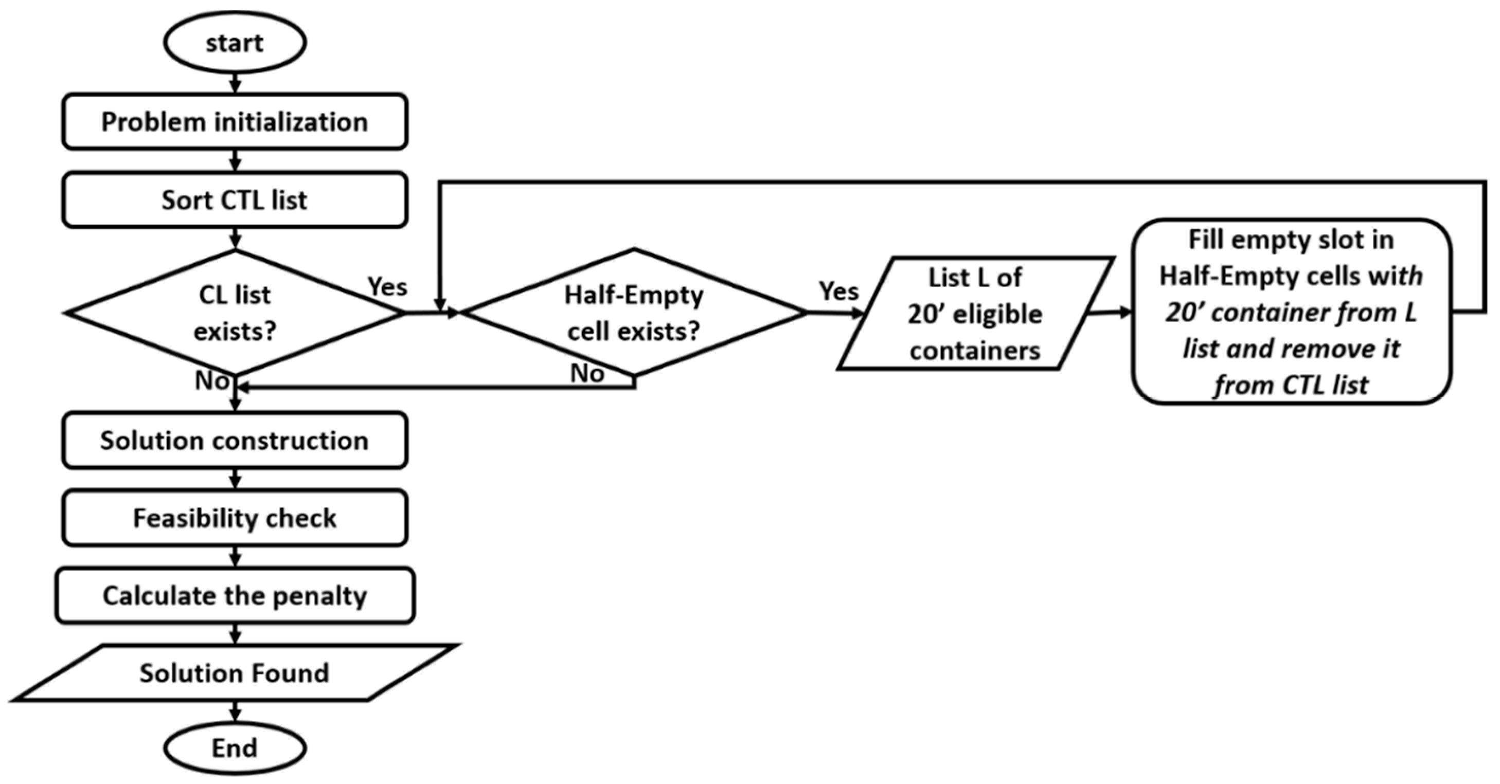
The proposed slot planning problem solution is an iterative process, as it pairs a container form the CTL list with a slot/cell in a certain stack from the set of eligible stacks . Figure 6, illustrates the flow chart of the proposed problem solution algorithm. The flow chart of Figure 6, contains the following main steps:
- Sort input Containers-To-Load (CTL) List as depicted in Section 3.1
- Fill empty slots in half-empty cells with 20′ containers from the CTL list as will be presented in Section 3.2
- Perform the Solution Construction with all necessary iteration as will be described in Section 3.3
- Compute the Feasibility Check and Penalty Calculation for the solution obtained above as will be discussed in Section 3.4
These steps are discussed in detail in the following sub-sections.
3.1. Sort Containers-to-Load (CTL) List
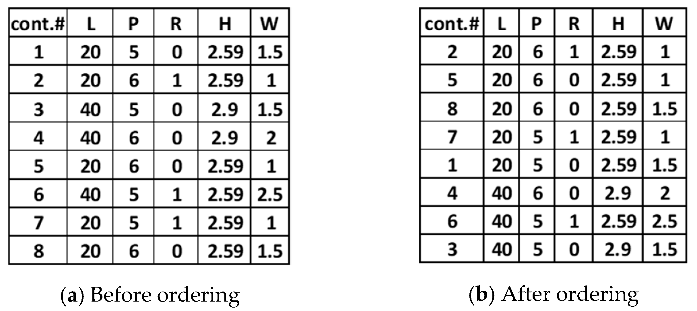
The containers in the CTL list are progressively sorted according to their length, POD, and whether they are reefer or not. The containers are first ordered in descending order according to their length. Then, all the containers of the same length are arranged according to their POD in a descending order to prevent overstowage. Finally, all the containers of the same POD are arranged according to their reefer characteristics: first the reefer, then the non-reefer containers.
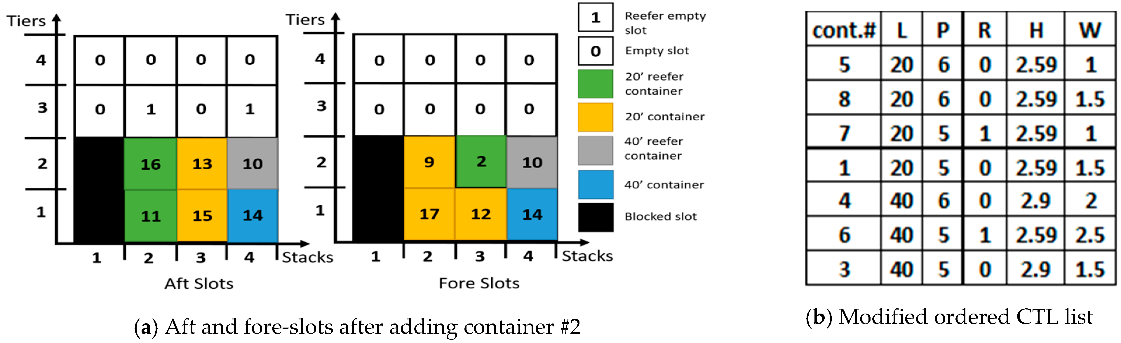
Figure 7, shows an example of the ordering of the CTL list, where (L, P, R, H, W) are the container’s length in feet, POD, reefer type (“0” for non-reefer and “1” for reefer), height in meters and weight in tons, respectively.
3.2. Fill Empty Slots in Half-Empty Cells with 20′ Containers from the CTL List
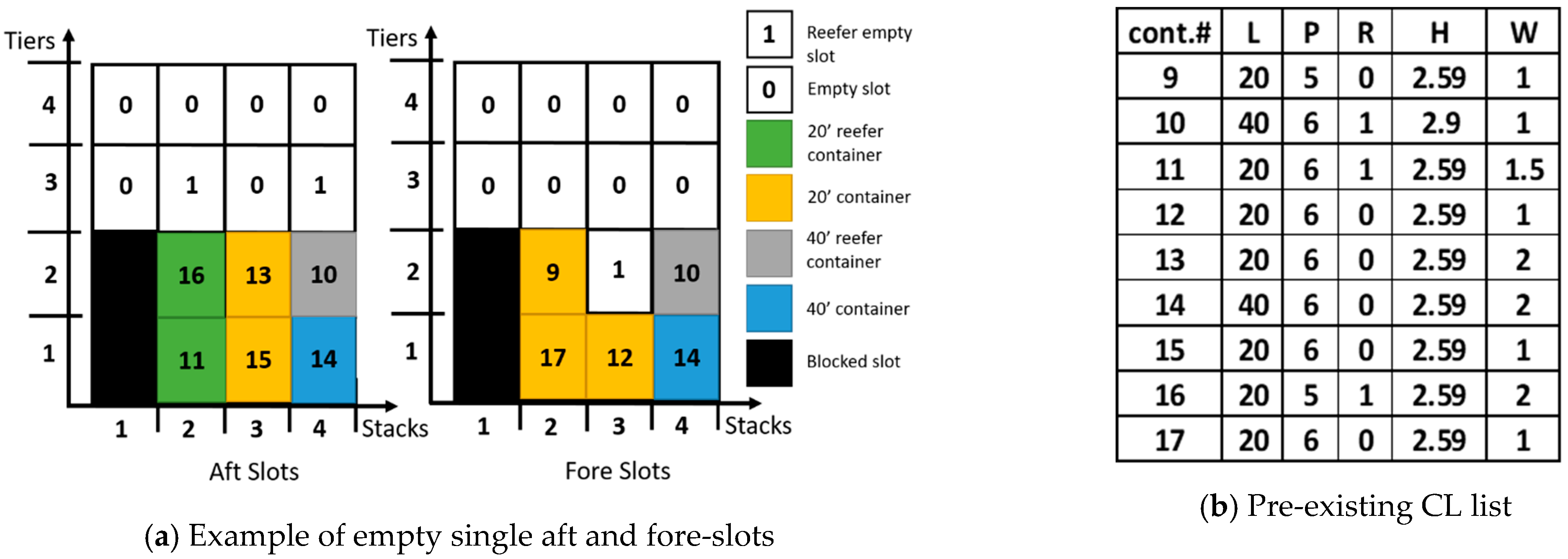
This step is fulfilled starting with a condition to check whether a pre-existing CL list exists. If so, the presence of single 20′ containers on their own in a cell (Half-Empty cells) is checked. If found, such a case would require another 20′ container matching the characteristics of the empty slot from the CTL list to be placed next to it. In order to do so, a list L of 20′ eligible containers is composed of the available CTL list fulfilling all the required conditions outlined earlier. Care must always be taken to consider whether this slot is a reefer slot or not. Moreover, it should have a POD of a number that is preferably equal to or less than the minimum POD for all the pre-existing containers found in this particular stack to avoid further handling moves during the unloading process.
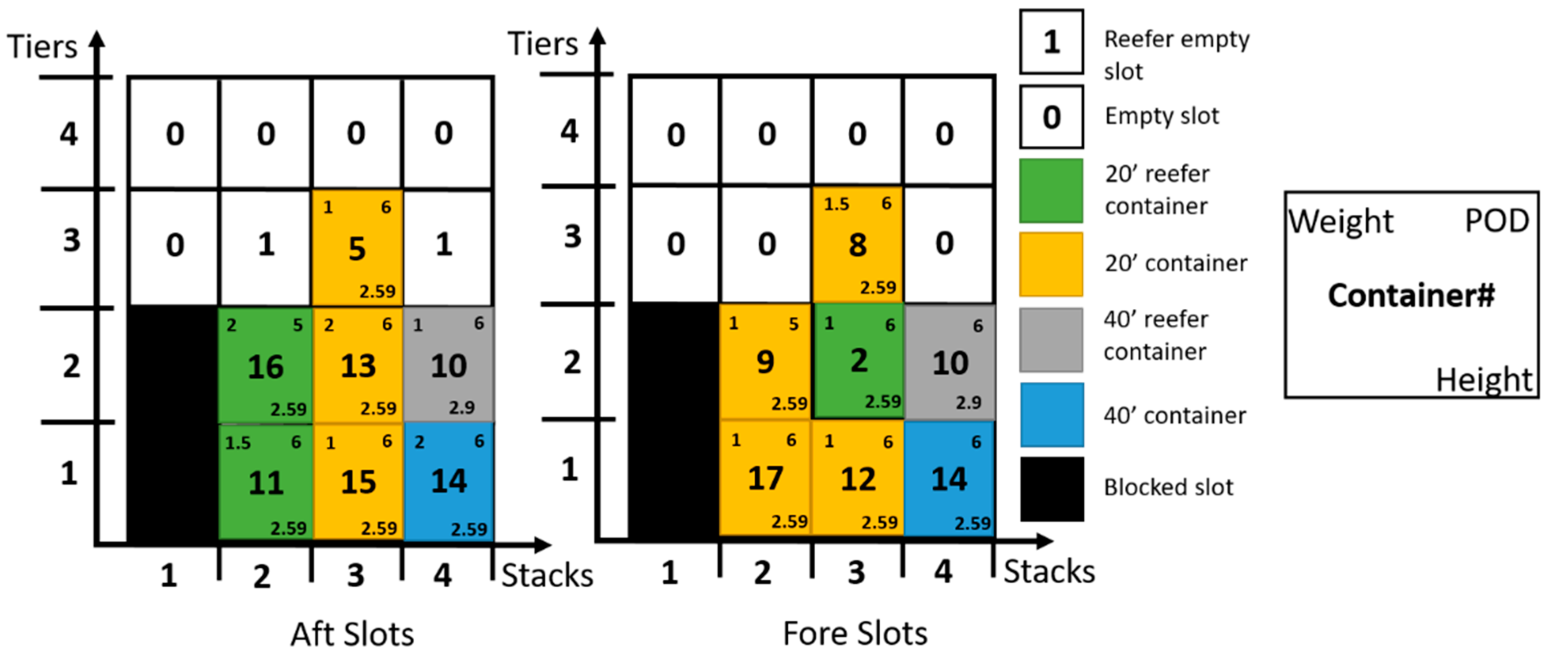
As an example, Figure 8a shows an example of the aft and fore-slots of a case of pre-loaded 20′ and 40′ containers from the CL list, shown in Figure 8b. The CL list shows containers numbered from 9 to 17, which are already allocated in the slots of Figure 8a. In this case, the cell in the third stack and the second tier only contains one 20′ container (#13). This container is placed in the aft-slot with no matching container in its corresponding fore-slot. This would incur the utilization of one of the 20′ containers from the CTL list to fill the corresponding empty fore-slot first before constructing the solution.
Referring to the example shown in Figure 8a, given that the slot is reefer, then from the ordered CTL list (shown in Figure 7b) single container that is 20′, reefer, and has a destination port of number 6 (preferably) or smaller is selected. The list () in this case would contain the following containers in the proper order (#2-reefer-port-6, #7-reefer-port-5, #5-non-reefer-port-6 and #8-non-reefer-port-6). In this case, container (#2) is selected since it has the same destination port and is a reefer container. The ordered CLT list is consequently updated by removing container #2 to become # (5, 8, 7, 1, 4, 6, and 3). The result of the problem after this step with the corresponding modified CTL list is then shown in Figure 9.
3.3. Solution Construction
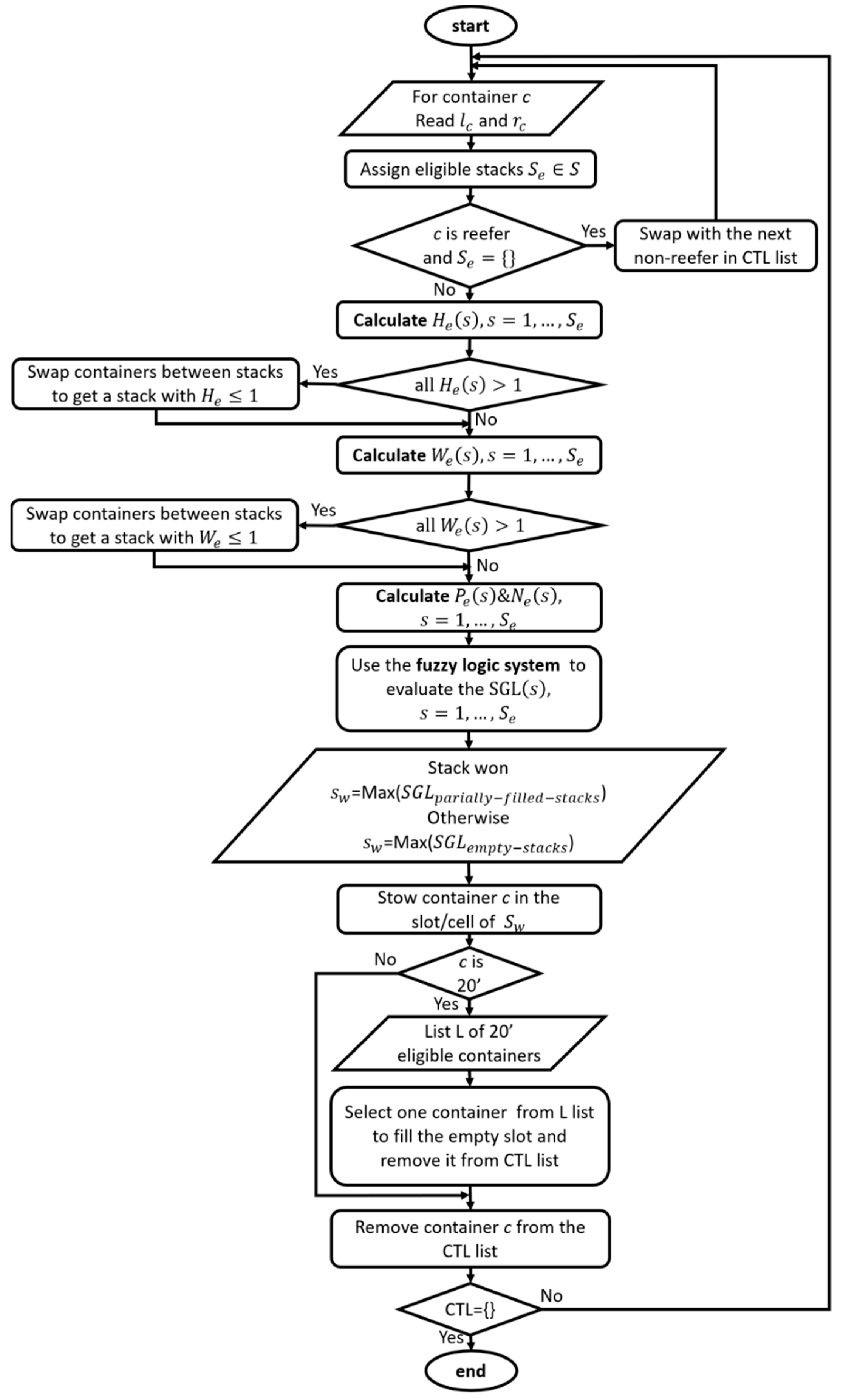
This is the main part of the algorithm. The corresponding details are shown in the flowchart of Figure 10. The flowchart mainly consists of a large loop for all the containers in the CTL list. The loop iterates until there are no more containers left in the CTL list. The main elements of the solution construction are:
- Assign eligible stacks
- Variables/Output Calculations: calculate the four variables of the slot planning fuzzy logic system ((, , and ) and use the fuzzy Mamdani fuzzy logic system to evaluate the output (SGL) for each stack
- Container Stowage: stow the container to the slot/cell and remove that container from the CTL list
3.3.1. Assign Eligible Stacks
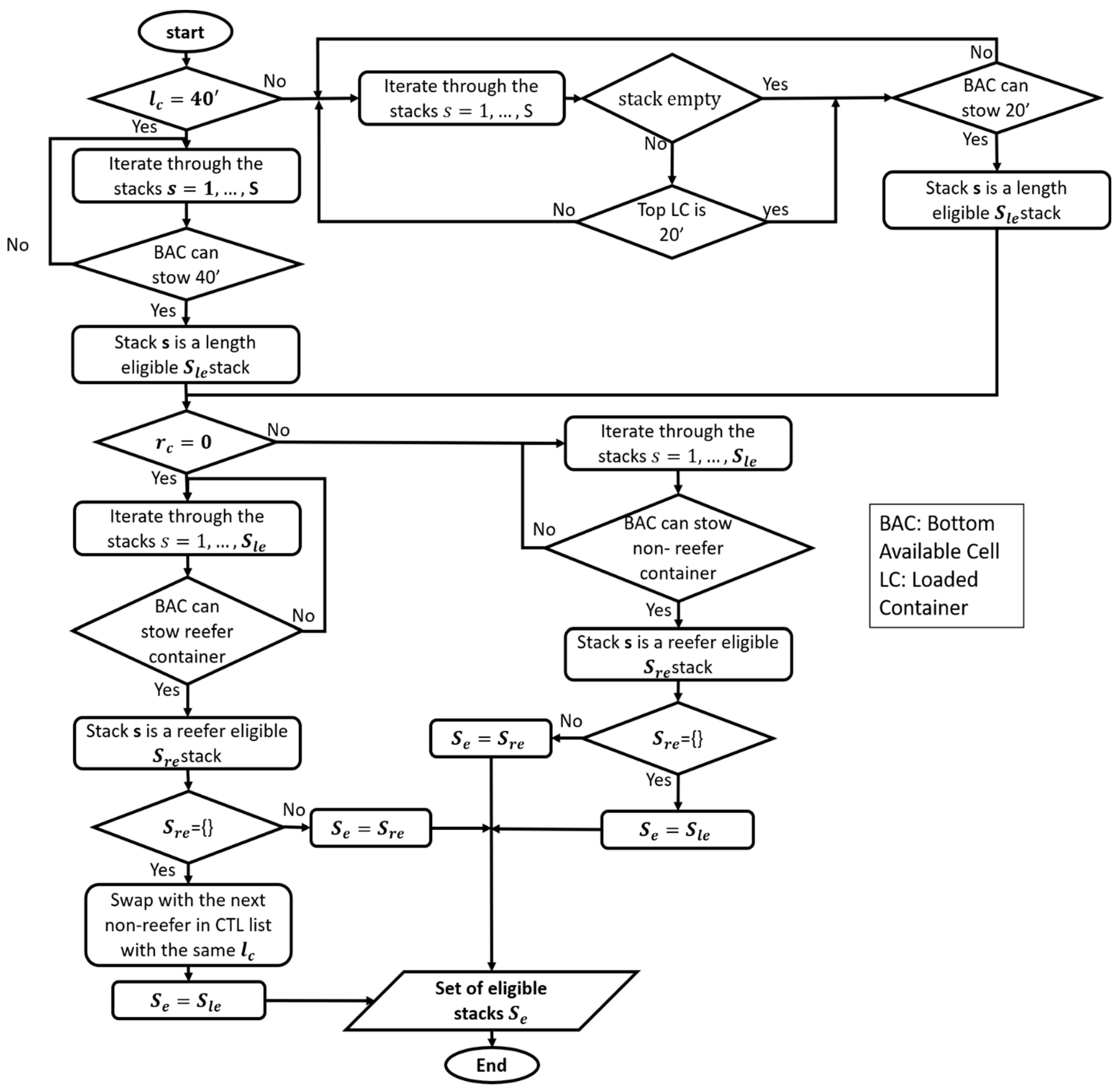
Initially, the information of a certain container (c) from the CTL list is considered. The length (lc = 20′ or 40′) and reefer characteristics (rc = 0 or 1) are used to assign allowable stacks to the set of eligible stacks () for this particular container (c) as shown in Figure 11.
First, the algorithm iterates through the stacks to assign the length eligible stacks ( and then from these () assign the reefer eligible stacks (). In the first step, two cases may arise, either the stack is empty or partially stacked. In the former, if the first available cell is eligible to stow this particular container of length () then this stack is added to the set (). In the latter, if then the top container in the stack must be 20′ as well and the first available cell is eligible to stow a 20′ container. However, if lc = 40′, then only one condition is checked; that the first available cell is eligible to stow 40′container. If these conditions are met, then add this stack to the set .
In the second step, we have two cases as well; first, if the container is reefer, then iterate through the stacks in the set . If the first available cell can stow a reefer container then add this stack to the set after all stacks are checked, then . One problem may arise if after all the stacks are checked and the set is empty then swap with the next non-reefer in the CTL list with the same as indicated by the first condition in the flowchart of Figure 10. If none exists in the CTL list, then the reefer container to be stowed is swapped with an already loaded non-reefer container stowed in a reefer cell from previous iterations. In this instance the container to be loaded is the non-reefer container the set of eligible stacks will be (.).
If the container is non-reefer, then we iterate through the stacks in the set . If the first available cell can stow a non-reefer container then we add this stack to the set after all stacks are checked then . One issue may arise if after all the stacks are checked and the set is empty then . This means that the non-reefer container will be added in a reefer cell/slot.
The solution construction sub-routine is applied to the same numerical example outlined in the previous sub-sections to clarify these steps. Consider the example case of container #5 (20′ non-reefer) at the top of the updated CTL list of Figure 9b.
3.3.2. Variables/Output Calculations
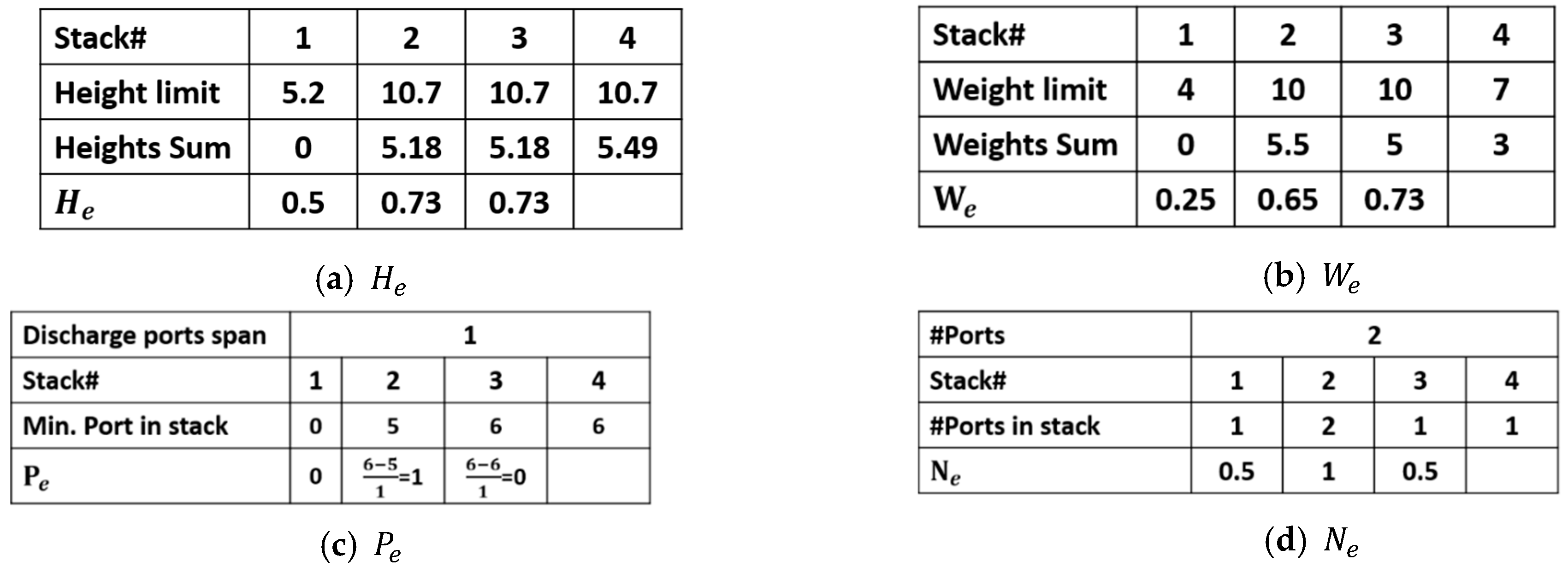
To use the fuzzy system, the four input variables (, , and ), outlined above, are calculated for each of the eligible stacks, using Equations (2)–(5) as follows:
- Height eligibility
- Weight eligibility
- Port eligibility
- Number of ports eligibility
Equations (2) and (3) compute the values of and input variables, which are crucial for the feasibility of the process. If the value of exceeds 1, this indicates that adding the container to this stack will violate the height constraint. If the value of for all eligible stacks are more than 1, then a rule-based search is performed to swap containers with some of the containers already assigned from the previous steps to get at least one of the eligible stacks with . The same procedure is re-applied if all the values of are more than 1 for all eligible stacks until a feasible case is reached.
is a variable that is related to the overstowage, and it is computed from Equation (4). The value of POD span between the furthest and nearest ports related to the whole problem. It controls the penalty value of the solution. In the odd cases where the stack is empty or that all destination ports are the same, the value of is irrelevant to the procedure. It is then assigned the value of 0 for the fuzzy logic module to function.
Finally, is a variable that is related to the number of PODs in each stack (less is better) computed when taking into consideration the POD of the container-to-load (c). This variable affects the penalty value of the solution.
The above computations of the four variables of interest to the fuzzy logic algorithm may be applied to the same numerical example outlined above to clarify these steps. The computations relating to container #5 for every stack are shown in Figure 12 for the set of eligible stacks (.)
The four fuzzy logic input variables (, , , and ) are then applied to the fuzzy logic algorithm implementation block. This process is repeated for each one of the stacks in the eligible stacks’ list (). The resulting output of the fuzzy logic block is the Stack-Goodness-Level (SGL) for each one of the eligible stacks, as outlined above. The partially-filled-stacks are considered first to avoid penalties for utilized a new stack. The partially-filled-stack, which has the maximum value, is the Stack-won ( = Max(SGLPartially-filled-stacks)). This stack is then selected.
3.3.3. Container Stowage
If no partially filled stacks are available, then a new empty stack with a maximum value of Stack-won ( = Max(SGLEmpty-stacks)) is selected. This way the destination stack for container c is assigned. The container is stowed in this particular stack. If container c is a 20′ container then another 20′ should be picked from the CTL list that conforms to the characteristics of the remaining free slot in the cell of that particular stack (). This process is performed in the same manner, as previously mentioned in the previous sub-section, using the list L of eligible 20′ containers. The CTL list is then updated by removing the utilized container(s). The above solution steps are repeated until the CTL list is empty.
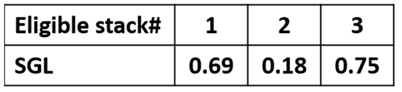
In the numerical example given above, SGL values for the eligible stacks () are listed in Figure 13. Stacks 2 and 3 are considered first since they are partially filled, while stack one is an empty stack. The maximum value of 0.75 conforms to stack 3. Consequently, . Container (#5) is then stowed in the aft-slot at the top of stack 3.
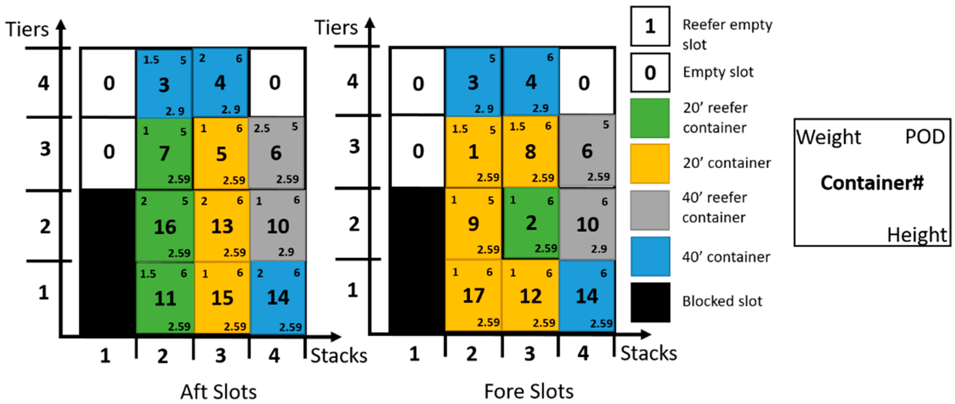
Since container (#5) has lc = 20′, another 20′ matching container is selected for the fore-slot. A list of eligible 20′ containers () is formed for containers having the same height, reefer characteristic, and POD. Container (#8) is chosen from the top of the CTL list for the fore-slot and the CTL list is updated. The resulting arrangement of the two new containers (#5 and #8) in their corresponding stacks is shown in Figure 14. It is important to mention that the representation of the containers changed by adding the information (weight, POD, and height) of each container to facilitate following the computations of the numerical example. The final complete solution of the proposed example problem is given in Figure 15.
3.4. Feasibility Check and Penalty Calculation
Given that some swaps may have been performed within the solution construction, a feasibility check is needed to ensure that the attained solution does not violate the constraints. This is followed by the calculation of the penalty values, outlined above, for the proposed solution. If the solution is infeasible then the algorithm failed to find a feasible solution to this instance.
4. Results and Discussion
The proposed approach was coded using MATLAB R2017a® and the instances were run on an Intel® Core i7™ CPU @ 3.6 GHz, and 8.00 GB RAM computer. The benchmark instances were proposed by Delgado et al. [7] and Pacino and Jensen [47] and later solved by Parreño et al. [2]. The instances include 236 slot planning benchmark instances partitioned into eleven different groups, where each one is a combination of instances that have similar features as shown in Table 2. All the 236 instances were solved by the proposed approach.
The first column represents the group ID, the second column indicates the number of instances in each group, and then the (maximum-minimum-average) available capacity of TEUs in each group is presented. This is followed by the (maximum-minimum-average) number of containers in (TEUs) in each group. The following columns indicate if the group has a specific feature; whether the group has containers that are 20′ or 40′ in size, High Cube (HC), and/or Reefer (R). The last three columns indicate the number of instances that have containers belonging to one, two, three, or more destination ports in each group.
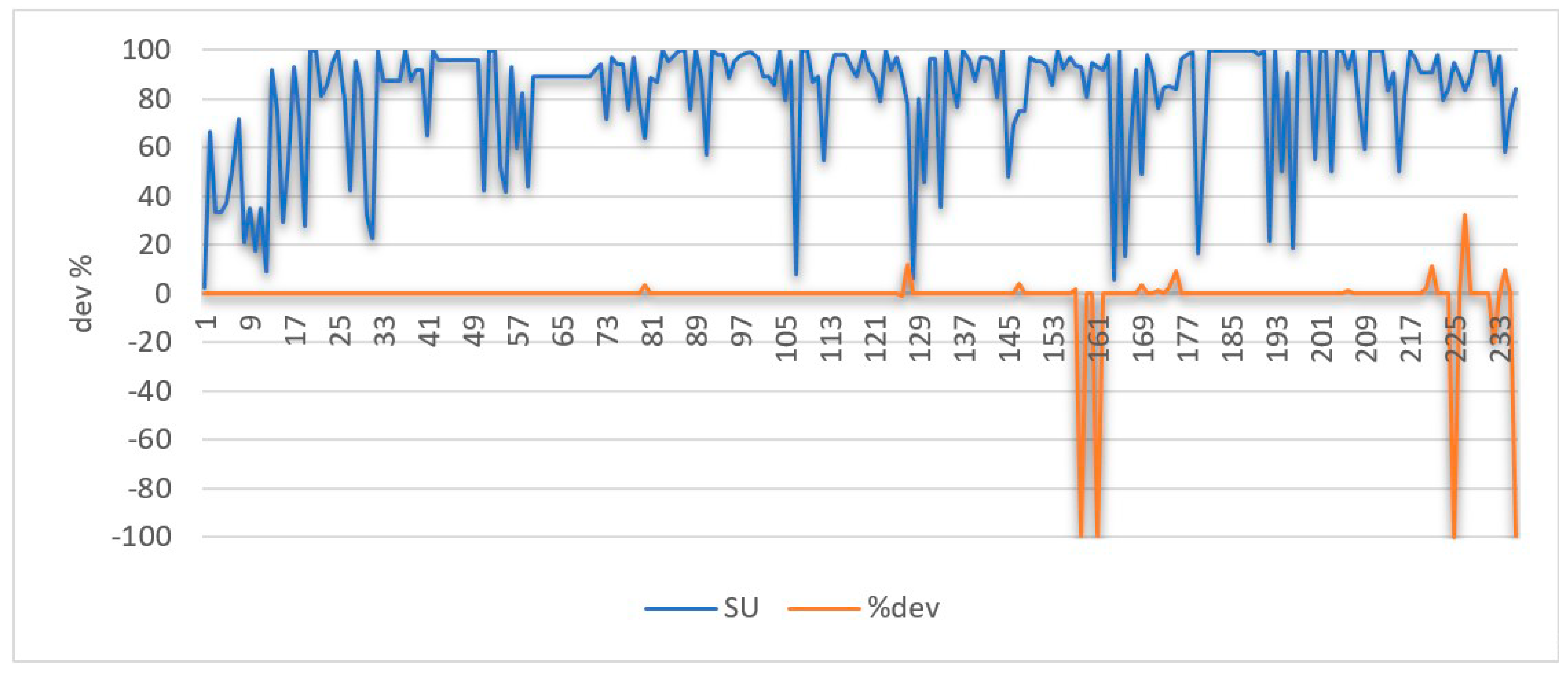
The instances are very realistic as almost 81% of the instances have a space utilization of more than 70%. The percentage of Space Utilization (SU) is defined in [2,7]. It is an indication of how full a certain location is with containers. It is calculated using the following formula:
These results are compared to the Integer Programming (IP) results of Delgado et al. [7]. Figure 16 shows the Space Utilization of the 236 instances as well as the percentage deviations from the upper-bound results obtained by Delgado et al. [7]. Even though a tighter solution was reached for instance #225 belonging to group 9, it was not considered a valid proper solution to compare. This is because in the proposed technique, the solution obtained was only possible after rolling-out two containers. In other words, these two containers remained in the CTL list and were not stowed. According to Parreño et al. [2], this instance has no feasible solution as both techniques found it impossible to reach a feasible solution for stowing all the containers in its CTL list.
The remaining 235 instances may be subdivided into the following two categories:
- The first category includes 222 instances of the 236 benchmark instances presented in Figure 16. Among these instances, four of which yielded tighter upper-bound that was reached by Integer Programming models of either Parreño et al. [2] or Delgado et al. [7]. The proposed results yielded improvements in these four instances of (99.5%, 99.5%, 20% and 99.7%) over the upper-bound of Delgado et al. [7]. All four instances have an average improvement of 80% for the four instances.
- The second category includes 13 instances. These instances do not have an optimum solution. As shown in Figure 16, the minimum, maximum and average percentage deviations from the optimum solution were 1.1%, 32%, and 7.2%, respectively.
- ○
- It is important to note that for nine instances out of these 13 instances, the only contributor to the deviation from the optimal solution was the reefer penalty (with an average of 3%). These instances belong to six different groups.
- ○
- After investigation, it was found that these instances had either, no to very few reefer containers to load. On the other hand, the location had a very high capacity of reefer slots. In these instances, if the relative difference between the number of reefer containers to load and the number of reefer cells in the location decreases, worse results are more likely to be achieved. These instances had an average Space Utilization percentage of 80%.
- ○
- Four of these nine instances belong to a group of instances that have no reefer containers but, in these locations, there exist a high number of reefer slots relating to the location’s dimension ranging from 8 to 64. These four instances have an average number of reefer slots that is equal to 25 and have a high number of HC containers regarding the number of the 40′ containers. In addition to having an average available capacity and utilization of 92 slots and 88%, respectively.
- ○
- Two instances of the 13 instances have an unnecessary stack opened to stow a single container. This is because the algorithm chooses the eligible stacks according to the reefer characteristics of the container to load. Given that at one stage of execution, this was the only stack that had the same reefer characteristic of the container to load, subsequently, this stack was opened.
- ○
- The algorithm also failed to find the optimum solution in the only instance of four port of destinations. The algorithm failed to perform better port clustering and yielded a deviation of 12% from the optimum solution.
- ○
- The worst case belonged to group #11 with a deviation value of 32% because of the overstowage penalty.
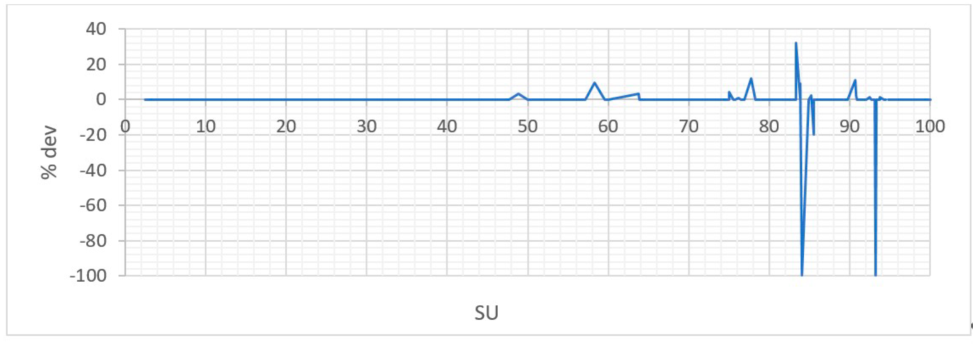
Figure 17 shows the deviations of Figure 16 plotted against the percentage of Space Utilization. The curve shows deviations occurring all in the range over 55% of the space utilization. This yields to the assumption that the larger values of the Space Utilization (SU) are susceptible to higher deviations.
Finally, the average time to obtain the solution was 0.4 s, which is satisfactory for the one second limitation discussed earlier. The results indicate that the proposed algorithm is effective and efficient in reaching the optimal solutions of the benchmark instances. The quality of the solutions is of a high standard as it was able to reach the optimum solution for most of the cases as will be demonstrated later in this section.
The performance of the proposed algorithm was compared against the following recently proposed solution approaches to solve the problem of slot planning of under deck locations:
The comparison is presented in Table 3. The first column indicates the group ID. Subsequently for each solution method, “%Sol” indicates the percentage of problems solved, “%Opt” depicts the percentage of problems solved optimally, and T(s) presents the total run-time needed to solve all the instances in the group.
From the results, the performance of the presented algorithm in terms of the quality of the solution is equivalent to the GRASP method in terms of the percentage solutions reached but not in terms of the percentage of optimal solutions reached. Additionally, the run times are almost the same. However, both CBLS and CP are much faster but the quality of the solutions is somewhat worse. It seems that the solutions are trapped in a local optimum. The CBLS is considered the fastest approach but fails to reach the optimum solutions in more cases. This can be attributed to getting stuck in a local optimum point.
The feasible 235 instances have lower bounds ranging from 30 to 4360 with an average of 235 and an average utilization that is equal to 82% and minimum and maximum values of 2.5% to 100%, respectively. This implies that the algorithm performs quite well with respect to time and optimum solutions achieved in easy and hard instances.
The performance of the algorithm declines for all instances that had an average lower bound and average utilization value of 290 and 78%, respectively.
Four out of the 13 worse instances belong to group 7, which has instances containing 20′, 40′, reefer, and HC containers combinations. The proposed algorithm only takes into consideration the reefer characteristic of the topmost available cell in each stack, and it does not consider the total stack reefer capacity as regards the reefer containers in the CTL list. This resulted in the use of stacks that had more reefer slots and ended up with more reefer penalties (PR) added to the objective function.
The presented approach is simple and can easily be implemented to consider more parameters as the IMOs. However, it might not be the best for a large number of PODs. This can be attributed to the performance in the instances that had more than three ports of destination. This condition was only present once in the tested cases (with four PODs). Further analysis with more test cases incorporating POD numbers larger than three needs to be conducted for such assertions. Nevertheless, this cannot be considered a drawback of the proposed solution approach as it is not imperative, because it is a good practice that the output of the master plan (first phase) emphasizes that each location does not have containers of more than three/four POD.
Additionally, the proposed algorithm does not look-ahead into the CTL list in assigning the list of eligible stacks for the current container. In other words, it can choose to add a reefer penalty PR = 5 for a non-reefer container rather than opening a new stack and adding discharge port and stack open penalties (PDP = 20 and PS = 10).
Given that that the used instances are real case instances that considers real data from the shipping company, they reflect the wide variety of cases of different sizes that are realistic, this implies that the proposed approach is applicable in the industry. The proposed approach is effective and can be used by the terminal’s operators to optimize the loading sequencing by taking the time of the container to be transported from the yard to the vessel as a fifth variable in the fuzzy logic system.
5. Conclusions
In this paper, the slot planning problem for underdeck locations of container vessels is solved. The paper focuses on the second phase of the decomposition approach to solve the stowage planning problem which is concerned with the slot planning problem. The approach is based on a rule-based fuzzy logic system was coupled with a rule-based search algorithm. The rules in the fuzzy logic algorithm and the search algorithm aimed at improving the objective function and minimize/eliminate constraint violation.
The computational results showed that the proposed approach is relatively fast. Out of 236 test instances, the algorithm was able to produce optimal solutions for 222 instances and 13 near-optimal solutions with an average deviation of 7.2%, with one instance producing an infeasible solution. The instances targeted the 20′/40′ (reefer/non-reefer) containers in less than 1 s, which is well within the time constraint for practical usage. The results elaborated the efficiency of the proposed algorithm when compared with the state-of-the-art algorithms and given that it is based on a rule-based approach; consequently, it has the potential to be generalized to incorporate IMO containers as well as the pallet-wide containers.
Future research may include extending the proposed approach to incorporate IMO containers as pallet-wide containers as a first step, subsequently to extend the CSPBDL to include on-deck locations and special containers such as out-of-gauge containers.
Author Contributions
Conceptualization, D.R.; methodology, D.R.; software, D.R.; validation, D.R., A.E. and M.G.; formal analysis, D.R., A.E. and M.G.; investigation, D.R., A.E. and M.G.; resources, D.R., A.E. and M.G.; data curation, D.R., A.E. and M.G.; writing—original draft preparation, D.R.; writing—review and editing, D.R., A.E. and M.G.; visualization, D.R., A.E. and M.G.; supervision, A.E. and M.G.; project administration, Not applicable; funding acquisition, Not applicable. All authors have read and agreed to the published version of the manuscript.
Funding
This research received no external funding.
Institutional Review Board Statement
Not applicable.
Informed Consent Statement
Not applicable.
Data Availability Statement
Not applicable.
Conflicts of Interest
The authors declare no conflict of interest.
References
- Stahlbock, R.; Steenken, D. Container terminal operation and operations research—A classification and literature review. In Container Terminals and Automated Transport Systems: Logistics Control Issues and Quantitative Decision Support; Springer: Berlin/Heidelberg, Germany, 2005; pp. 3–49. [Google Scholar]
- Parreno, F.; Pacino, D.; Alvarez-Valdes, R. A GRASP algorithm for the container stowage slot planning problem. Transp. Res. Part E Logist. Transp. Rev. 2016, 94, 141–157. [Google Scholar] [CrossRef] [Green Version]
- Lun, Y.H.V.; Lai, K.-H.; Cheng, T.C. Investigation of the influences of ‘transport complex economy’ and political risk on freight transport growth. Int. J. Logist. Res. Appl. 2011, 14, 285–296. [Google Scholar] [CrossRef]
- Tanaka, S.; Voß, S. An exact algorithm for the block relocation problem with a stowage plan. Eur. J. Oper. Res. 2019, 279, 767–781. [Google Scholar] [CrossRef]
- Maritime Shipping and International Trade. 2021. Available online: https://porteconomicsmanagement.org/pemp/contents/part1/maritime-shipping-and-international-trade/world-container-throughput/ (accessed on 20 January 2021).
- Bilican, M.S.; Evren, R.; Karatas, M. A Mathematical Model and Two-Stage Heuristic for the Container Stowage Planning Problem with Stability Parameters. IEEE Access 2020, 8, 113392–113413. [Google Scholar] [CrossRef]
- Delgado, A.; Jensen, R.M.; Janstrup, K.H.; Rose, T.H.; Andersen, K.H. A Constraint Programming model for fast optimal stowage of container vessel bays. Eur. J. Oper. Res. 2012, 220, 251–261. [Google Scholar] [CrossRef]
- Monaco, M.F.; Sammarra, M.; Sorrentino, G. The Terminal-Oriented Ship Stowage Planning Problem. Eur. J. Oper. Res. 2014, 239, 256–265. [Google Scholar] [CrossRef]
- Pacino, D.; Delgado, A.; Jensen, R.M.; Bebbington, T. Fast Generation of Near-Optimal Plans for Eco-Efficient Stowage of Large Container Vessels. In Proceedings of the International Conference on Computational Logistics, Hamburg, Germany, 19–22 September 2011; Volume 6971, pp. 286–301. [Google Scholar] [CrossRef] [Green Version]
- Shi, W.; Li, K.X. Themes and tools of maritime transport research during 2000–2014. Marit. Policy Manag. 2016, 44, 151–169. [Google Scholar] [CrossRef]
- Fazi, S. A decision-support framework for the stowage of maritime containers in inland shipping. Transp. Res. Part E Logist. Transp. Rev. 2019, 131, 1–23. [Google Scholar] [CrossRef]
- Parthibaraj, C.S.; Palaniappan, P.; Gunasekaran, A.; Subramanian, N. Multi-agent system with iterative auction mechanism for master bay plan problem in marine logistics. Marit. Policy Manag. 2017, 44, 705–726. [Google Scholar] [CrossRef]
- Li, J.; Zhang, Y.; Ji, S.; Zheng, L. Solving inland container ship stowage planning problem on full route through a two-phase approach. Int. J. Shipp. Transp. Logist. 2020, 12, 65. [Google Scholar] [CrossRef]
- Korach, A.; Brouer, B.D.; Jensen, R.M. Matheuristics for slot planning of container vessel bays. Eur. J. Oper. Res. 2020, 282, 873–885. [Google Scholar] [CrossRef]
- Wang, N.; Yu, L.; Yu, L.; Ke, S. Optimization of Containership Stowage in Circular Route Based on Greedy Algorithm. In Proceedings of the 2020 IEEE 4th Information Technology, Networking, Electronic and Automation Control Conference (ITNEC), Chongqing, China, 12–14 June 2020; pp. 146–150. [Google Scholar] [CrossRef]
- Cohen, M.W.; Coelho, V.N.; Dahan, A. Container Vessel Stowage Planning System Using Genetic Algorithm. In Lecture Notes in Computer Science; Springer: Cham, Switzerland, 2017; Volume 10199, pp. 557–572. [Google Scholar]
- Wilson, I.D.; Roach, P.A. Container stowage planning: A methodology for generating computerised solutions. J. Oper. Res. Soc. 2000, 51, 1248–1255. [Google Scholar] [CrossRef]
- Pacino, D.; Jensen, R.M. Fast Slot Planning Using Constraint-Based Local Search. In IAENG Transactions on Engineering Technologies: Special Issue of the International MultiConference of Engineers and Computer Scientists 2012; Yang, G.-C., Ao, S.-I., Huang, X., Castillo, O., Eds.; Springer: Dordrecht, The Netherlands, 2013; Volume 186, pp. 49–63. [Google Scholar]
- Ambrosino, D.; Sciomachen, A. Using a Bin Packing Approach for Stowing Hazardous Containers into Containerships. In Optimized Packings with Applications; Fasano, G., Ed.; Springer: Cham, Switzerland, 2015; Volume 105, pp. 1–18. [Google Scholar]
- Ambrosino, D.; Anghinolfi, D.; Paolucci, M.; Sciomachen, A. A new three-step heuristic for the Master Bay Plan Problem. Marit. Econ. Logist. 2009, 11, 98–120. [Google Scholar] [CrossRef]
- Ambrosino, D.; Anghinolfi, D.; Paolucci, M.; Sciomachen, A. An Experimental Comparison of Different Heuristics for the Master Bay Plan Problem. In Proceedings of the 9th International Symposium on Experimental Algorithms, Naples, Italy, 20–22 May 2010; pp. 314–325. [Google Scholar] [CrossRef]
- Expósito-izquierdo, C.; Melián-batista, B.; Moreno-vega, J.M. A Review of Soft Computing Techniques in Maritime Logistics and Its Related Fields. In Soft Computing Based Optimization and Decision Models, Studies in Fuzziness and Soft Computing; Springer: Cham, Switzerland, 2018; Volume 360, pp. 1–23. [Google Scholar]
- De Azevedo, A.T.; De Arruda, E.F.; Salles-Neto, L.; Chaves, A.A.; Moretti, A.C. Solution of the 3D Stochastic Stowage Planning for Container Ships through Representation by Rules. In Proceedings of the Fourth International Workshop on Knowledge Discovery, Knowledge Management and Decision Support, Mazatlan, Mexico, 6–8 November 2013; pp. 120–129. [Google Scholar] [CrossRef] [Green Version]
- Araújo, E.J.; Chaves, A.; Salles-Neto, L.; De Azevedo, A.T. Pareto clustering search applied for 3D container ship loading plan problem. Expert Syst. Appl. 2016, 44, 50–57. [Google Scholar] [CrossRef]
- Pacino, D. An LNS Approach for Container Stowage Multi-port Master Planning. In Lecture Notes in Computer Science (Including Subseries Lecture Notes in Artificial Intelligence and Lecture Notes in Bioinformatics); Springer: Berlin/Heidelberg, Germany, 2013; Volume 8197, pp. 35–44. [Google Scholar] [CrossRef]
- Gheith, M.; Eltawil, A.B.; Harraz, N.A. Solving the container pre-marshalling problem using variable length genetic algorithms. Eng. Optim. 2015, 48, 687–705. [Google Scholar] [CrossRef]
- Güven, C.; Eliiyi, D.T. Modelling and optimisation of online container stacking with operational constraints. Marit. Policy Manag. 2018, 46, 201–216. [Google Scholar] [CrossRef]
- Avriel, S.; Penn, M.; Shpirer, M.; Witteboon, N. Stowage planning for container ships to reduce the number of shifts. Ann. Oper. Res. 1998, 76, 55–71. [Google Scholar] [CrossRef]
- Dubrovsky, O.; Levitin, G.; Penn, M. A Genetic Algorithm with a Compact Solution Encoding for the Container Ship Stowage Problem. J. Heuristics 2002, 8, 585–599. [Google Scholar] [CrossRef]
- Ding, D.; Chou, M.C. Stowage planning for container ships: A heuristic algorithm to reduce the number of shifts. Eur. J. Oper. Res. 2015, 246, 242–249. [Google Scholar] [CrossRef]
- Rahsed, D.M.; Gheith, M.S.; Eltawil, A.B. A Rule-based Greedy Algorithm to Solve Stowage Planning Problem. In Proceedings of the 2018 IEEE International Conference on Industrial Engineering and Engineering Management (IEEM), Bangkok, Thailand, 16–19 December 2018; pp. 437–441. [Google Scholar]
- Roberti, R.; Pacino, D. A Decomposition Method for Finding Optimal Container Stowage Plans. Transp. Sci. 2018, 52, 1444–1462. [Google Scholar] [CrossRef]
- De Azevedo, A.T.; Ribeiro, C.M.; De Sena, G.J.; Chaves, A.A.; Neto, L.L.S.; Moretti, A.C. Solving the 3D container ship loading planning problem by representation by rules and beam search. In Proceedings of the 1st International Conference on Operations Research and Enterprise Systems, Algarve, Portugal, 4–6 February 2012; pp. 132–141. [Google Scholar] [CrossRef]
- De Azevedo, A.T.; Ribeiro, C.M.; De Sena, G.J.; Chaves, A.; Neto, L.L.S.; Moretti, A.C. Solving the 3D container ship loading planning problem by representation by rules and meta-heuristics. Int. J. Data Anal. Tech. Strat. 2014, 6, 228–260. [Google Scholar] [CrossRef]
- De Azevedo, A.C.; de Arruda, A.T.; Neto, E.F.; Chaves, L.L.S.; Moretti, A.A. On the application of participatory learning system for solving the 3d loading and unloading containers in port terminals for multiple scenarios. Rev. Pesqui. Nav. Brasília 2015, 27, 57–68. [Google Scholar]
- Azevedo, A.T.; Salles-Neto, L.; Chaves, A.; Moretti, A.C. Solving the 3D stowage planning problem integrated with the quay crane scheduling problem by representation by rules and genetic algorithm. Appl. Soft Comput. 2018, 65, 495–516. [Google Scholar] [CrossRef]
- Lee, Z.Q.; Fan, R.; Hsu, W.-J. Towards Real-Time Automated Stowage Planning—Optimizing Constraint Test Ordering. In Proceedings of the International Conference on Computational Logistics, Lisbon, Portugal, 7–9 September 2016; pp. 175–189. [Google Scholar] [CrossRef]
- Lee, Z.Q.; Fan, R.; Hsu, W.-J. A Near-Optimal Algorithm for Constraint Test Ordering in Automated Stowage Planning. IEEE Trans. Autom. Sci. Eng. 2018, 15, 1298–1308. [Google Scholar] [CrossRef]
- Wilson, I.; Roach, P. Principles of Combinatorial Optimization Applied to Container-Ship Stowage Planning. J. Heuristics 1999, 5, 403–418. [Google Scholar] [CrossRef]
- Kang, J.-G.; Kim, Y.-D. Stowage planning in maritime container transportation. J. Oper. Res. Soc. 2002, 53, 415–426. [Google Scholar] [CrossRef]
- Pacino, D.; Delgado, A.; Jensen, R.M.; Bebbington, T. An Accurate Model for Seaworthy Container Vessel Stowage Planning with Ballast Tanks. In Lecture Notes in Computer Science (Including Subseries Lecture Notes in Artificial Intelligence and Lecture Notes in Bioinformatics); Springer: Berlin/Heidelberg, Germany, 2012; Volume 7555, pp. 17–32. [Google Scholar] [CrossRef]
- Ambrosino, D.; Paolucci, M.; Sciomachen, A. Experimental evaluation of mixed integer programming models for the multi-port master bay plan problem. Flex. Serv. Manuf. J. 2015, 27, 263–284. [Google Scholar] [CrossRef]
- Ambrosino, D.; Paolucci, M.; Sciomachen, A. Computational evaluation of a MIP model for multi-port stowage planning problems. Soft Comput. 2015, 21, 1753–1763. [Google Scholar] [CrossRef]
- Ambrosino, D.; Paolucci, M.; Sciomachen, A. A MIP Heuristic for Multi Port Stowage Planning. Transp. Res. Procedia 2015, 10, 725–734. [Google Scholar] [CrossRef] [Green Version]
- Delgado, A.; Jensen, R.M.; Schulte, C. Generating Optimal Stowage Plans for Container Vessel Bays. In Lecture Notes in Computer Science (Including Subseries Lecture Notes in Artificial Intelligence and Lecture Notes in Bioinformatics); Springer: Berlin/Heidelberg, Germany, 2009; Volume 5732, pp. 6–20. [Google Scholar] [CrossRef]
- Pacino, D.; Jensen, R. A Local Search Extended Heuristic for Stowing Under Deck Locations of Container Vessels. In Proceedings of the ODYSSEUS 2009—The 4th International Workshop on Freight Transportation and Logistics, Cesme-Izmir, Turkey, 26–29 May 2009; pp. 1–3. [Google Scholar]
- Pacino, D.; Jensen, R.M. Constraint-Based Local Search for Container Stowage Slot Planning. In Lecture Notes in Computer Science (Including Subseries Lecture Notes in Artificial Intelligence and Lecture Notes in Bioinformatics); Springer: Berlin/Heidelberg, Germany, 2012; Volume 2, pp. 1467–1472. [Google Scholar]
- Ries, J.; González-Ramírez, R.G.; Miranda, P.A. A Fuzzy Logic Model for the Container Stacking Problem at Container Terminals. In Lecture Notes in Computer Science (Including Subseries Lecture Notes in Artificial Intelligence and Lecture Notes in Bioinformatics); Springer: Berlin/Heidelberg, Germany, 2014; Volume 8760, pp. 93–111. [Google Scholar] [CrossRef] [Green Version]
- Valdes-Gonzalez, H.; Reyes-Bozo, L.; Vyhmeister, E.; Salazar, J.L.; Sepúlveda-Rojas, J.P.; Mosca-Arestizábal, M. Container stacking revenue management system: A fuzzy-based strategy for Valparaiso port. DYNA 2015, 82, 38–45. [Google Scholar] [CrossRef]
- Rekik, I.; Elkosantini, S. A multi agent system for the online container stacking in seaport terminals. J. Comput. Sci. 2019, 35, 12–24. [Google Scholar] [CrossRef]
- Atef, S.; Ismail, N.; Eltawil, A.B. A new fuzzy logic based approach for optimal household appliance scheduling based on electricity price and load consumption prediction. Adv. Build. Energy Res. 2021, 1–19. [Google Scholar] [CrossRef]
- Xia, M.; Li, Y.; Shen, Y.; Zhao, N. Loading Sequencing Problem in Container Terminal with Deep Q-Learning. J. Coast. Res. 2020, 103, 817–821. [Google Scholar] [CrossRef]
- Aghda, S.A.F.; Mirfakhraei, M. Improved routing in dynamic environments with moving obstacles using a hybrid Fuzzy-Genetic algorithm. Futur. Gener. Comput. Syst. 2020, 112, 250–257. [Google Scholar] [CrossRef]
- Voloshyn, A.; Gnatienko, G.; Drobot, E. Fuzzy Membership Functions in a Fuzzy Decision Making Problem. Int. J. Inf. Theor. Appl. 2003, 10, 243–247. [Google Scholar]
- Wang, C. A Study of Membership Functions on Mamdani-Type Fuzzy Inference System for Industrial Decision-Making. Master’s Thesis, Lehigh University, Bethlehem, PA, USA, 2015. [Google Scholar]
Figure 1.
The stowage planning decomposition into a master planning phase and a slot planning phase.
Figure 1.
The stowage planning decomposition into a master planning phase and a slot planning phase.

Figure 2.
The Elements of the Slot Planning Problem.

Figure 3.
A partially filled location with containers denoted by their destination ports. The second stack has an over-stowing container.
Figure 3.
A partially filled location with containers denoted by their destination ports. The second stack has an over-stowing container.

Figure 4.
The Mamdani-type fuzzy system and its elements.

Figure 5.
Membership functions of the input variables.

Figure 6.
Flow Chart of the Solution Approach.

Figure 7.
CTL list before and after progressive ordering according to length, POD, and reefer type.

Figure 8.
Numerical example with pre-existing containers (#9 to #17) with their characteristics.

Figure 9.
Pre-existing containers (#9 to #17) after adding container #2 from the modified CTL list.

Figure 10.
Overview of the solution construction.

Figure 11.
Assigning the eligible stacks for the container to stow.

Figure 12.
Computations of and for the given example relating to container #5.

Figure 13.
Resulting values of SGL from the fuzzy logic algorithm block for each stack of the eligible stack list (.
Figure 13.
Resulting values of SGL from the fuzzy logic algorithm block for each stack of the eligible stack list (.

Figure 14.
Arrangement of containers after adding containers #5 and #8.

Figure 15.
Final arrangement of all containers in the CTL list.

Figure 16.
Comparison of calculated SU and the percentage deviation of obtained results from the upper-bound results of Delgado et al. [7] for the 236 simulated instances.
Figure 16.
Comparison of calculated SU and the percentage deviation of obtained results from the upper-bound results of Delgado et al. [7] for the 236 simulated instances.

Figure 17.
Relation between space utilization percentage and solution deviation from the upper bound solutions of the instances.
Figure 17.
Relation between space utilization percentage and solution deviation from the upper bound solutions of the instances.


Table 1.
Sets, penalties, and decision variables used in this problem.
| Sets | |
|---|---|
| Set of 20′ containers | |
| Set of 40′ containers | |
| Penalties | |
| POS | Penalty for each Over-Stowed container |
| PDP | Penalty for each Ports of Discharge (PODs) within a stack |
| PS | Penalty for an open Stack |
| PR | Penalty for stowing a non-reefer container in a Reefer cell/slot |
| Decision Variables | |
| is an overstowing container or not | |
| or not | |
| is empty or not | |
| or not | |
Table 2.
Instances groups and characteristics [2].
Table 2.
Instances groups and characteristics [2].
| Group | No. of Inst. | Capacity (TEU) | No. of Containers (TEU) | 40′ | 20′ | HC | R | No. of Destination Ports | ||||||
|---|---|---|---|---|---|---|---|---|---|---|---|---|---|---|
| Min. | Max. | Avg. | Min. | Max. | Avg. | 1 | 2 | ≥3 | ||||||
| 1 | 13 | 16 | 116 | 63 | 8 | 116 | 54 | √ | 13 | |||||
| 2 | 22 | 8 | 168 | 68 | 8 | 136 | 52 | √ | 22 | |||||
| 3 | 13 | 30 | 124 | 74 | 8 | 124 | 68 | √ | √ | 13 | ||||
| 4 | 78 | 6 | 208 | 79 | 2 | 202 | 63 | √ | √ | 78 | ||||
| 5 | 36 | 38 | 176 | 97 | 8 | 170 | 81 | √ | √ | √ | 36 | |||
| 6 | 15 | 42 | 172 | 73 | 16 | 74 | 46 | √ | √ | √ | 15 | |||
| 7 | 14 | 72 | 204 | 147 | 24 | 202 | 117 | √ | √ | √ | √ | 14 | ||
| 8 | 14 | 40 | 148 | 96 | 40 | 136 | 87 | √ | √ | √ | 14 | |||
| 9 | 17 | 44 | 220 | 124 | 36 | 200 | 111 | √ | √ | √ | √ | 15 | 2 | |
| 10 | 8 | 72 | 176 | 122 | 10 | 156 | 93 | √ | √ | √ | 6 | 2 | ||
| 11 | 6 | 48 | 176 | 101 | 28 | 148 | 84 | √ | √ | √ | √ | 3 | 3 | |
Table 3.
Comparing results from Fuzzy logic with GRASP, CBLS heuristic, and Constraint Programming (CP) algorithms.
Table 3.
Comparing results from Fuzzy logic with GRASP, CBLS heuristic, and Constraint Programming (CP) algorithms.
| Grp# | #Inst | Fuzzy | GRASP(1 s) | CBLS | CP(10 s) | ||||||||
|---|---|---|---|---|---|---|---|---|---|---|---|---|---|
| %Sol | %Opt | T(s) | %Sol | %Opt | T(s) | %Sol | %Opt | T(s) | %Sol | %Opt | T(s) | ||
| 1 | 13 | 100 | 100 | 4.52 | 100 | 100 | 6.3 | 100 | 59 | 0.1 | 100 | 100 | 0.1 |
| 2 | 22 | 100 | 95 | 8.12 | 100 | 100 | 15.4 | 100 | 77 | 3.6 | 91 | 91 | 21.6 |
| 3 | 13 | 100 | 100 | 5.1 | 100 | 100 | 7.8 | 100 | 92 | 0.5 | 100 | 100 | 0.5 |
| 4 | 78 | 100 | 100 | 28.32 | 100 | 99 | 37.3 | 100 | 92 | 6 | 99 | 99 | 19.7 |
| 5 | 36 | 100 | 94 | 16.41 | 100 | 94 | 22.3 | 97 | 58 | 7.1 | 92 | 92 | 39 |
| 6 | 15 | 100 | 93 | 4.68 | 100 | 100 | 6 | 93 | 80 | 1.2 | 100 | 100 | 5.4 |
| 7 | 14 | 100 | 71 | 6.66 | 100 | 93 | 9 | 93 | 79 | 2.3 | 64 | 64 | 53.5 |
| 8 | 14 | 100 | 100 | 6.4 | 100 | 100 | 6.1 | 93 | 43 | 1.5 | 93 | 93 | 10.5 |
| 9 | 17 | 94 | 82 | 8.69 | 94 | 82 | 12.3 | 94 | 47 | 5.2 | 88 | 88 | 36.5 |
| 10 | 8 | 100 | 88 | 3.33 | 100 | 100 | 4.8 | 100 | 88 | 0.7 | 100 | 100 | 0.7 |
| 11 | 6 | 100 | 67 | 2.56 | 100 | 83 | 3.2 | 50 | 17 | 1.3 | 83 | 83 | 10.3 |
Publisher’s Note: MDPI stays neutral with regard to jurisdictional claims in published maps and institutional affiliations. |
© 2021 by the authors. Licensee MDPI, Basel, Switzerland. This article is an open access article distributed under the terms and conditions of the Creative Commons Attribution (CC BY) license (https://creativecommons.org/licenses/by/4.0/).
Share and Cite
MDPI and ACS Style
Rashed, D.; Eltawil, A.; Gheith, M. A Fuzzy Logic-Based Algorithm to Solve the Slot Planning Problem in Container Vessels. Logistics 2021, 5, 67. https://0-doi-org.brum.beds.ac.uk/10.3390/logistics5040067
AMA Style
Rashed D, Eltawil A, Gheith M. A Fuzzy Logic-Based Algorithm to Solve the Slot Planning Problem in Container Vessels. Logistics. 2021; 5(4):67. https://0-doi-org.brum.beds.ac.uk/10.3390/logistics5040067
Chicago/Turabian StyleRashed, Dalia, Amr Eltawil, and Mohamed Gheith. 2021. "A Fuzzy Logic-Based Algorithm to Solve the Slot Planning Problem in Container Vessels" Logistics 5, no. 4: 67. https://0-doi-org.brum.beds.ac.uk/10.3390/logistics5040067