Article

Investigation of Nanographene Produced by In-Liquid Plasma for Development of Highly Durable Polymer Electrolyte Fuel Cells

Department of Electrical and Electronic Engineering, Meijo University, 1-501 Shiogamaguchi, Tempaku, Nagoya 468-8502, Japan
*
Author to whom correspondence should be addressed.
Submission received: 31 October 2018 / Revised: 14 November 2018 / Accepted: 17 November 2018 / Published: 23 November 2018
(This article belongs to the Special Issue Plasma Processing for Carbon-based Materials)

Abstract

:
Recently, polymer electrolyte fuel cells (PEFCs) are attracting a lot of attention owing to their small size and relatively low working temperature (below 80 °C), which enables their usage in automobiles and household power generation. However, PEFCs have a problem with decreased output caused by corrosion of amorphous carbon, which is commonly used as a catalytic carrier. This problem could be solved by the usage of carbon nanostructures with a stronger crystal structure than amorphous carbon. In this work, nanographene supported by Pt nanoparticles was synthesized and examined for possible applications in the development of PEFCs with increased durability. Nanographene was synthesized by in-liquid plasma generated in ethanol using alternating current (AC) high voltage. A membrane electrode assembly (MEA) was constructed, where Pt nanoparticle-supported nanographene was used as the catalytic layer. Power generation characteristics of the MEA were evaluated and current density for the developed MEA was found to be approximately 240 mA/cm2. From the electrochemical evaluation, it was found that the durability of Pt nanoparticle-supported nanographene was about seven times higher than that of carbon black.

Graphical Abstract

1. Introduction

Recently, ecological problems such as global warming and the depletion of fossil fuels have received a lot of attention. One promising way to solve such problems is the development and use of fuel cells as an energy source [1,2,3]. In contrast to commonly used fossil fuels, fuel cells could generate power with hydrogen and oxygen, and emit only water without greenhouse gases [3]. Among fuel cells, polymer electrolyte fuel cells (PEFCs) are attracting a lot of attention owing to their small size and relatively low working temperature (below 80 °C), which enables their usage in automobiles and household power generation [3,4,5,6]. Typically, platinum (Pt) nanoparticles (NPs) are used as a catalyst and carbon black (CB) is used as a support material for the catalyst in a PEFC [7]. A key characteristic of Pt NPs for power generation is an effective electrochemical surface area (ESA), which is defined as the ratio of the surface to volume of the Pt catalyst [1,7,8]. A significant decrease in the ESA of Pt NPs supported by CB is observed after 5000–6000 start-stop cycles under applied voltage [1,5,6,7,8,9,10,11,12]. This decrease is related to the low quality of CB, which leads to corrosion of carbon and results in aggregation of Pt NPs [5,6,7,8,9,10,11,12]. Reduction of the lifespan due to CB degradation is a serious problem, which could be solved by improvement of the durability of the catalyst support material [1,9]. One way to improve durability is by use of carbon nanostructures, which have a stronger crystal structure and are more durable than amorphous carbon [1,12].
In recent work, carbon nanotubes (CNTs), carbon nanowalls (CNWs) and graphene sheets have been widely studied as support material for the catalyst in PEFCs owing to their unique properties, such as high chemical stability, high thermal conductivity, high electron mobility and large specific area [1,2,13,14,15]. It was found that carbon nanomaterials provide higher durability compared to CB, showing promise for increasing the lifespan of PEFCs [1,2,16,17]. It was confirmed that CB durability was improved by surface graphitization, suggesting high-quality graphene sheets may be a perfect candidate for a highly-durable catalyst support material [1,2,18]. However, high-quality several-layered graphene sheets are typically synthesized using complicated technological processes, such as chemical vapor deposition (CVD), which is performed using high temperatures (up to 1000 °C) and low pressure, and requires preparation of the catalyst before synthesis [18,19,20,21,22,23]. Moreover, due to the large number of variable parameters in CVD, it is extremely difficult to optimize the fabrication process [24,25]. Complicated growth process, slow speed of growth and expensive equipment results in a high price of produced graphene and makes it unreliable for development of highly-durable PEFCs.
A new method of synthesis of nanographene has been reported by Hagino et al. [26]. In this work, nanographene is defined as a stack of several layers of graphene fragments of size ranging from 1 to 100 nm. This method allows the production of high-crystallinity nanographene with a high synthesis rate (up to 0.61 mg/min) using low-cost equipment operated at atmospheric pressure [2,16,17,26]. The high synthesis rate and low production cost makes this method attractive for production of highly-durable catalyst support materials.
Therefore, in the present work nanographene was synthesized using the above-mentioned method and studied as a high durability catalyst support material for the development of long-lifespan PEFCs. A catalyst of Pt NPs was loaded onto nanographene synthesized by in-liquid plasma, and a membrane electrode assembly (MEA) was created with the Pt NP-supported nanographene and used as the core of fuel cell. The possibility of using nanographene as the catalytic carrier is discussed on the basis of an evaluation of its power generation characteristics.

2. Experimental Setup

Figure 1a shows a schematic of in-liquid plasma apparatus. A quantity of 100 mL of ethanol was fed into the beaker as shown in Figure 1b. Ar gas was introduced with a flow rate of 5 slm into the upper part of beaker and the beaker was maintained at atmospheric pressure. The upper copper (Cu) rod electrode was placed in the gas phase when the lower Cu plate electrode was immersed in the ethanol.
The synthesized material (Figure 1c) was collected by suction filtration and was a composite of amorphous carbon and nanographene. The amorphous carbon component was removed by treatment in hydrogen peroxide (H2O2) at a temperature of 80 °C [27]. After treatment, Pt NPs were loaded onto the surface of the nanographene by the reduction of Pt salt precursor (H2Cl6Pt) in the solution. Catalyst ink was created by mixing the Pt NP-supported nanographene and ionomer. Carbon fiber paper was coated with the catalyst ink and dried to form a catalyst layer. In the next step, a MEA was constructed by thermal compression bonding of two catalyst layers with a proton exchange membrane introduced between them at a temperature of 130 °C and pressure of 7 MPa. For construction of the fuel cell, EFC Fuel Cell Hardware EFC-05-02 (ElectroChem Inc., Woburn, MA, USA) was used.
Electrochemical measurements were carried out to estimate surface area of Pt NPs and evaluate the durability of the Pt NP-supported nanographene as a catalyst layer of a PEFC. The ESA of the Pt NPs was measured by cyclic voltammetry using a standard three-electrode setup with a Solartron SI 1287 potentiostat (Solartron Analytical, Leicester, England). For evaluation of durability, the high-potential cycle test was performed up to 140,000 cycles with voltage varied from 1 to 1.5 V during the cycle. Electrical evaluation was carried out using AutoPEM dual fuel cell test system (Toyo Corporation, Tokyo, Japan).
Raman spectra for the deposits were measured at room temperature with a triple monochromator Jobin Yvon Ramanor T64000 (Horiba, Kyoto, Japan) and the 532 nm line of a Diode-Pumped Solid-State Laser. The transmission electron microscope (TEM) H-7650 (Hitachi, Tokyo, Japan) was used for observation of Pt NP-supported nanographene and SmartLab diffractometer (Rigaku Corporation, Tokyo, Japan) was used for X-ray diffraction (XRD) measurements.

3. Results and Discussion

3.1. Synthesis and Evaluation of Nanographene

The Raman spectra of nanographenes before and after hydrogen peroxide treatment are shown in Figure 2. Four peaks typical for nanographene were clearly visible in both spectra. A G-band peak at 1590 cm−1 indicating the formation of a graphitized structure and D-band peak at 1350 cm−1 corresponding to the disorder-induced phonon mode were confirmed. The G-band peak was accompanied by a shoulder peak at 1620 cm−1 (D’-band), which is associated with finite-size graphite crystals and graphene edges. The 2D-band peak at 2690 cm−1 is used to confirm the presence of graphene and originates from a double resonance process that links phonons to the electronic band structure. The relatively strong and sharp D-band peak and D’-band peak suggest a nanocrystalline structure and the presence of graphene edges and defects, which confirm generation of nanographene using in-liquid plasma. However, a strong background spectrum (vertical striped lines) and broadening of the G-band peak indicate a significant amount of amorphous carbon which is not suitable for use as a catalyst support material for development of a PEFC, as was indicated in the introduction.
A common method to remove the amorphous carbon component from synthesized nanocarbons is treatment in H2O2; moreover, it has been confirmed that amorphous component could be removed selectively from nanographene by H2O2 treatment [27]. From the Raman spectrum (Figure 2) it was found that the background spectrum was lowered and the full width at half maximum (FWHM) of G-band peak was reduced from 46 to 30 cm−1 by the H2O2 treatment, confirming the effective removal of the amorphous carbon component from the synthesized nanographene. Nanographene with reduced amount of amorphous component after H2O2 treatment looks promising for use as a catalyst support material in PEFCs.

3.2. Supporting Pt Nanoparticles to Nanographene

After purification, the synthesized nanographene was loaded with Pt NPs by the liquid-phase reduction method using Pt precursor (H2Cl6Pt) in the solution. The TEM images of nanographenes before and after supporting Pt particles are shown in Figure 3a,b. From Figure 3a it can be observed that nanographene with sizes ranging from 10 to 100 nm were synthesized by in-liquid plasma. Moreover, the TEM image in Figure 3b clearly shows that Pt particles were successfully supported on a surface of nanographene from a Pt salt precursor in the solution. The size of Pt particles could be estimated to be in the range of 2–5 nm and the particles could be identified as Pt NPs.
The size of Pt NPs was also confirmed using XRD measurement of Pt-supported nanographene. The XRD spectrum of Pt-supported nanographene is shown in Figure 3c. From the XRD spectrum the size of nanoparticles could be calculated using Scherrer’s equation:
D = K × λ / ( β × cos θ )
where K is a dimensionless shape factor, λ is wavelength of X-ray, β is FWHM of the diffraction peak (rad), and θ is the Bragg angle (location of the maximum of the diffraction peak, rad). Using fitting and deconvolution of the diffraction peak observed in XRD spectrum, from Equation (1) it could be estimated that the size of the crystallite of Pt was 3.06 nm. The calculated results correlate with the diameter of the Pt NPs observed in TEM images, confirming that Pt NPs with a diameter of approximately 3 nm could be loaded onto the surface of nanographene by the liquid-phase reduction method.

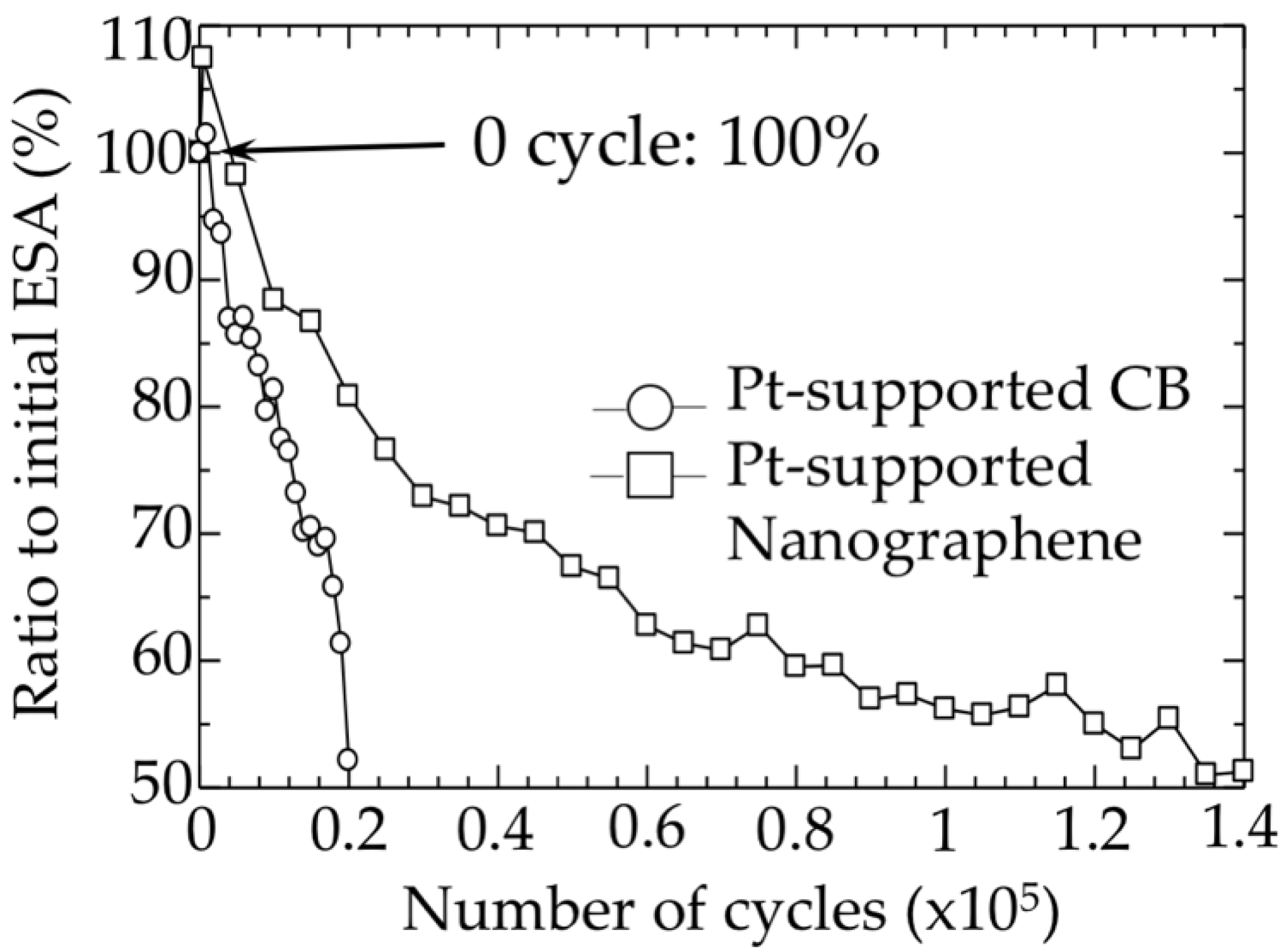
3.3. Durability Evaluation of Nanographene

To confirm the applicability of produced nanographene supported with Pt NPs as a catalyst layer of a PEFC it is necessary to perform high electric potential durability tests. To compare durability of nanographene and CB, the high-potential cycle test was performed for both materials with up to 140,000 cycles. During the test, potential was varied from 1 to 1.5 V with a duration cycle of two seconds. Figure 4 shows the result of the durability evaluation of Pt NP-supported nanographene and conventional CB. At the start of the measurements (0 cycle) ESA was 100% for both catalyst materials and increased to 102% for CB and to 107% for nanographene during opening cycles (first 100 cycles). After 20,000 cycles of the high electric potential test, the estimated ESA for Pt NP-supported CB decreased to 52% of its initial value, while the ESA for Pt NP-supported nanographene decreased only to 81%. These results clearly show that durability of Pt NP-supported nanographene was significantly higher than that of CB.
As was indicated in the introduction, the rapid decrease in ESA for CB is related to aggregation of Pt NPs on the surface of the CB. To confirm aggregation of Pt NPs, CB and nanographene were observed using TEM before and after high electric potential durability tests; results are presented in Figure 5.
From TEM images it was observed that before the high electric potential durability test, the diameter of Pt NPs on the surface of CB was in the range of 2–3 nm (Figure 5a). The diameter increased to 4–6 nm after 20,000 cycles due to aggregation of nanoparticles (Figure 5b). This increase of diameter led to a decrease of the Pt NPs surface to about 50% of its initial value. In the case of nanographene, the initial diameter of nanoparticles was in the range of 2–3 nm (Figure 5c) and increased to 3–4 nm after 20,000 cycles of the test (Figure 5d), resulting in a decrease of surface to about 80% of its initial value.
Observed results confirm that the decrease of ESA is related to aggregation of nanoparticles and show that nanographene is more reliable as a catalyst supporting material owing to its higher stability compared to CB. Moreover, it could be observed that in the case of Pt NP-supported nanographene, the ESA decreased to 50% of initial value after 140,000 cycles, which is seven times more than the number of cycles for CB, which suggests that nanographene loaded with Pt NPs is promising as a catalyst layer for development of high-durability PEFCs.

3.4. Power Generation Characteristic of MEA

For development of a PEFC using nanographene loaded with Pt NPs it is necessary to check power generation characteristics. Catalyst ink was created by mixing the Pt NP-supported nanographene and ionomer, and carbon fiber was coated with the ink and dried to form a catalyst layer. A MEA was constructed by thermal compression bonding of two catalyst layers and introducing a proton exchange membrane between them. Figure 6 shows the current density and the power density of the fabricated MEA using Pt NP-supported nanographene as catalyst layer.
Power generation using the produced MEA was confirmed and the current density was approximately 240 mA/cm2. Results show that Pt NP-supported nanographene has potential for the development of a highly-durable PEFC; however, measured current density for Pt NP-supported CNWs was 420 mA/cm2 and for Pt NP-supported CB Vulcan XC 72R (Cabot Corporation, Alpharetta, GA, USA) was 840 mA/cm2. Moreover, current densities of up to 1000 mA/cm2 have been reported elsewhere [28], which is four times more than the value for Pt NP-supported nanographene. Considering a similar mass percentage of platinum loaded to the surface of nanographene (30 wt. %) and CB (20–50 wt. %), the low current density could be explained by two factors: poor dispersion of nanographene in ionomer and low adhesion of the catalyst layer to the ion exchange membrane. Due to poor dispersion of nanographene in ionomer, the ionomer did not reach all of the Pt NPs, resulting in ineffective use of the catalyst during tests and a reduction of power generation characteristics. On the other hand, problems with adhesion to the ion exchange membrane resulted in a decrease of conductivity between the ion exchange membrane and the catalyst layer, which limited the current. Both of these problems could be solved by optimization and improvement of the MEA fabrication process.
Results presented in this work confirm that nanographene produced by in-liquid plasma could be used as support material for a Pt NPs catalyst in PEFCs; however, for practical application further improvement in the fabrication process and optimization of synthesis parameters are required.

4. Conclusions

Synthesis of nanographene was performed using in-liquid plasma and amount of the amorphous component was reduced by H2O2 treatment. Pt NPs with a diameter of approximately 3 nm were loaded onto the surface of synthesized nanographene by the reduction of Pt salt precursors. A catalytic layer of the fuel cell was fabricated with Pt NP-supported nanographene. From the evaluation of the power generation characteristics of the MEA, current density of approximately 240 mA/cm2 was registered. Moreover, it was confirmed that Pt NP-supported nanographene had seven times higher durability than the conventional carbon black. Further improvement in the fabrication process and optimization of synthesis parameters are required for improvement of power generation characteristics of Pt NP-supported nanographene.

Author Contributions

V.G. analyzed experimental results and wrote the paper, K.K. conducted experiments and measurements; K.T. performed enrichment experiments, M.H. supervised the project.

Funding

This research was funded by MEXT-Supported Program for the Strategic Research Foundation at Private Universities, grant number S1511021.

Conflicts of Interest

The authors declare no conflict of interest.

References

  1. Imai, S.; Kondo, H.; Cho, H.; Kano, H.; Ishikawa, K.; Sekine, M.; Hiramatsu, M.; Ito, M.; Hori, M. High-durability catalytic electrode composed of pt nanoparticle-supported carbon nanowalls synthesized by radical-injection plasma-enhanced chemical vapor deposition. J. Phys. D Appl. Phys. 2017, 50, 40LT01. [Google Scholar] [CrossRef]
  2. Amano, T.; Kondo, H.; Takeda, K.; Ishikawa, K.; Hiramatsu, M.; Sekine, M.; Hori, M. Nanographene synthesized in triple-phase plasmas as a highly durable support of catalysts for polymer electrolyte fuel cells. Jpn. J. Appl. Phys. 2018, 57, 045101. [Google Scholar] [CrossRef]
  3. Jacobson, M.Z. Cleaning the air and improving health with hydrogen fuel-cell vehicles. Science 2005, 308, 1901–1905. [Google Scholar] [CrossRef] [PubMed]
  4. Ohma, A.; Shinohara, K.; Iiyama, A.; Yoshida, T.; Daimaru, A. Membrane and catalyst performance targets for automotive fuel cells by FCCJ membrane, catalyst, MEA WG. ECS Trans. 2011, 41, 775–784. [Google Scholar] [CrossRef]
  5. Litster, S.; McLean, G. PEM fuel cell electrodes. J. Power Sources 2004, 130, 61–76. [Google Scholar] [CrossRef]
  6. Knights, S.D.; Colbow, K.M.; St-Pierre, J.; Wilkinson, D.P. Aging mechanisms and lifetime of PEFC and DMFC. J. Power Sources 2004, 127, 127–134. [Google Scholar] [CrossRef]
  7. Hara, M.; Lee, M.; Liu, C.H.; Chen, B.H.; Yamashita, Y.; Uchida, M.; Uchida, H.; Watanabe, M. Electrochemical and raman spectroscopic evaluation of Pt/graphitized carbon black catalyst durability for the start/stop operating condition of polymer electrolyte fuel cells. Electrochim. Acta 2012, 70, 171–181. [Google Scholar] [CrossRef]
  8. Stevens, D.A.; Hicks, M.T.; Haugen, G.M.; Dahn, J.R. Ex situ and in situ stability studies of PEMFC catalysts. J. Electrochem. Soc. 2005, 152, A2309–A2315. [Google Scholar] [CrossRef]
  9. De Bruijn, F.A.; Dam, V.A.T.; Janssen, G.J.M. Review: Durability and degradation issues of PEM fuel cell components. Fuel Cells 2008, 8, 3–22. [Google Scholar] [CrossRef]
  10. Taniguchi, A.; Akita, T.; Yasuda, K.; Miyazaki, Y. Analysis of degradation in PEMFC caused by cell reversal during air starvation. J. Power Sources 2004, 130, 42–49. [Google Scholar] [CrossRef]
  11. Mehta, V.; Cooper, J.S. Review and analysis of PEM fuel cell design and manufacturing. J. Power Sources 2003, 114, 32–53. [Google Scholar] [CrossRef]
  12. Steele, B.C.H.; Heinzel, A. Materials for fuel-cell technologies. Nature 2001, 414, 345–352. [Google Scholar] [CrossRef] [PubMed]
  13. Wang, X.; Li, W.; Chen, Z.; Waje, M.; Yan, Y. Durability investigation of carbon nanotube as catalyst support for proton exchange membrane fuel cell. J. Power Sources 2006, 158, 154–159. [Google Scholar] [CrossRef]
  14. Shao, Y.; Zhang, S.; Wang, C.; Nie, Z.; Liu, J.; Wang, Y.; Lin, Y. Highly durable graphene nanoplatelets supported Pt nanocatalysts for oxygen reduction. J. Power Sources 2010, 195, 4600–4605. [Google Scholar] [CrossRef]
  15. Kongkanand, A.; Kuwabata, S.; Girishkumar, G.; Kamat, P. Single-wall carbon nanotubes supported platinum nanoparticles with improved electrocatalytic activity for oxygen reduction reaction. Langmuir 2006, 22, 2392–2396. [Google Scholar] [CrossRef] [PubMed]
  16. Amano, T.; Kondo, H.; Ishikawa, K.; Tsutsumi, T.; Takeda, K.; Hiramatsu, M.; Sekine, M.; Hori, M. Rapid growth of micron-sized graphene flakes using in-liquid plasma employing iron phthalocyanine-added ethanol. Appl. Phys. Express 2018, 11, 015102. [Google Scholar] [CrossRef]
  17. Ando, A.; Ishikawa, K.; Kondo, H.; Tsutsumi, T.; Takeda, K.; Ohta, T.; Ito, M.; Hiramatsu, M.; Sekine, M.; Hori, M. Nanographene synthesis employing in-liquid plasmas with alcohols or hydrocarbons. Jpn. J. Appl. Phys. 2018, 57, 026201. [Google Scholar] [CrossRef]
  18. Mase, K.; Kondo, H.; Kondo, S.; Hori, M.; Hiramatsu, M.; Kano, H. Formation and mechanism of ultrahigh density platinum nanoparticles on vertically grown graphene sheets by metal-organic chemical supercritical fluid deposition. Appl. Phys. Lett. 2011, 98, 193108. [Google Scholar] [CrossRef]
  19. Chen, L.; Hernandez, Y.; Feng, X.; Müllen, K. From nanographene and graphene nanoribbons to graphene sheets: Chemical synthesis. Angew. Chem. Int. Ed. 2012, 51, 2–17. [Google Scholar] [CrossRef] [PubMed]
  20. Ferrari, A.C. Raman spectroscopy of graphene and graphite: Disorder, electron-phonon coupling, doping and nonadiabatic effects. Solid State Commun. 2007, 143, 47–57. [Google Scholar] [CrossRef]
  21. Reina, A.; Jia, X.; Ho, J.; Nezich, D.; Son, H.; Bulovic, V.; Dresselhaus, M.S.; Kong, J. Large area, few-layer graphene films on arbitrary substrates by chemical vapor deposition. Nano Lett. 2009, 9, 30–35. [Google Scholar] [CrossRef] [PubMed]
  22. Hummers, W.S.; Offeman, R.E. Preparation of graphitic oxide. J. Am. Chem. Soc. 1958, 80, 1339. [Google Scholar] [CrossRef]
  23. Shao, G.; Lu, Y.; Wu, F.; Yang, C.; Zeng, F.; Wu, Q. Graphene oxide: The mechanisms of oxidation and exfoliation. J. Mater. Sci. 2012, 47, 4400–4409. [Google Scholar] [CrossRef]
  24. Pander, A.; Ishimoto, K.; Hatta, A.; Furuta, H. Significant decrease in the reflectance of thin CNT forest films tuned by the Taguchi method. Vacuum 2018, 154, 285–295. [Google Scholar] [CrossRef]
  25. Pander, A.; Hatta, A.; Furuta, H. Optimization of catalyst formation conditions for synthesis of carbon nanotubes using Taguchi method. Appl. Surf. Sci. 2016, 371, 425–435. [Google Scholar] [CrossRef]
  26. Hagino, T.; Kondo, H.; Ishikawa, K.; Kano, H.; Sekine, M.; Hori, M. Ultrahigh-speed synthesis of nanographene using alcohol in-liquid plasma. Appl. Phys. Express 2012, 5, 035101. [Google Scholar] [CrossRef]
  27. Feng, Y.; Zhou, G.; Wang, G.; Qu, M.; Yu, Z. Removal of some impurities from carbon nanotubes. Chem. Phys. Lett. 2003, 375, 645–648. [Google Scholar] [CrossRef]
  28. Barz, D.P.J.; Schmidt, V.M. Addition of dilute H2O2 solutions to H2-CO fuel gases and their influence on performance of a PEFC. Phys. Chem. Chem. Phys. 2001, 3, 330–332. [Google Scholar] [CrossRef]
Figure 1. A schematic diagram of an in-liquid plasma device (a), liquid before the plasma treatment (b), and liquid after the plasma treatment (c).
Carbon 04 00065 g001
Figure 2. Raman spectra of nanographene before and after hydrogen peroxide treatment.
Carbon 04 00065 g002
Figure 3. Transmission electron microscope (TEM) images of synthesized nanographene (a), nanographene loaded with Pt nanoparticles (b) and XRD spectrum of Pt nanoparticles supported nanographene (c).
Carbon 04 00065 g003
Figure 4. High electric potential durability test result of Pt nanoparticle-supported carbon black and nanographene.
Carbon 04 00065 g004
Figure 5. Carbon black loaded with Pt nanoparticles before (a) and after (b) 20,000 cycles, and nanographene loaded with Pt nanoparticles before (c) and after (d) 20,000 cycles of high electric potential durability tests.
Carbon 04 00065 g005
Figure 6. Current density and power density of a fabricated membrane electrode assembly (MEA) using Pt nanoparticle-supported nanographene as a catalyst layer.
Carbon 04 00065 g006

