
Review of Cryogenic Carbon Capture Innovations and Their Potential Applications


Department of Engineering, University of Hull, Hull HU6 7RX, UK
*
Author to whom correspondence should be addressed.
C 2021, 7(3), 58; https://0-doi-org.brum.beds.ac.uk/10.3390/c7030058
Submission received: 21 June 2021
/
Revised: 22 July 2021
/
Accepted: 26 July 2021
/
Published: 29 July 2021
(This article belongs to the Special Issue Carbon Materials for Physical and Chemical Hydrogen Storage)
Abstract
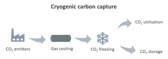
:Our ever-increasing interest in economic growth is leading the way to the decline of natural resources, the detriment of air quality, and is fostering climate change. One potential solution to reduce carbon dioxide emissions from industrial emitters is the exploitation of carbon capture and storage (CCS). Among the various CO2 separation technologies, cryogenic carbon capture (CCC) could emerge by offering high CO2 recovery rates and purity levels. This review covers the different CCC methods that are being developed, their benefits, and the current challenges deterring their commercialisation. It also offers an appraisal for selected feasible small- and large-scale CCC applications, including blue hydrogen production and direct air capture. This work considers their technological readiness for CCC deployment and acknowledges competing technologies and ends by providing some insights into future directions related to the R&D for CCC systems.
1. Introduction
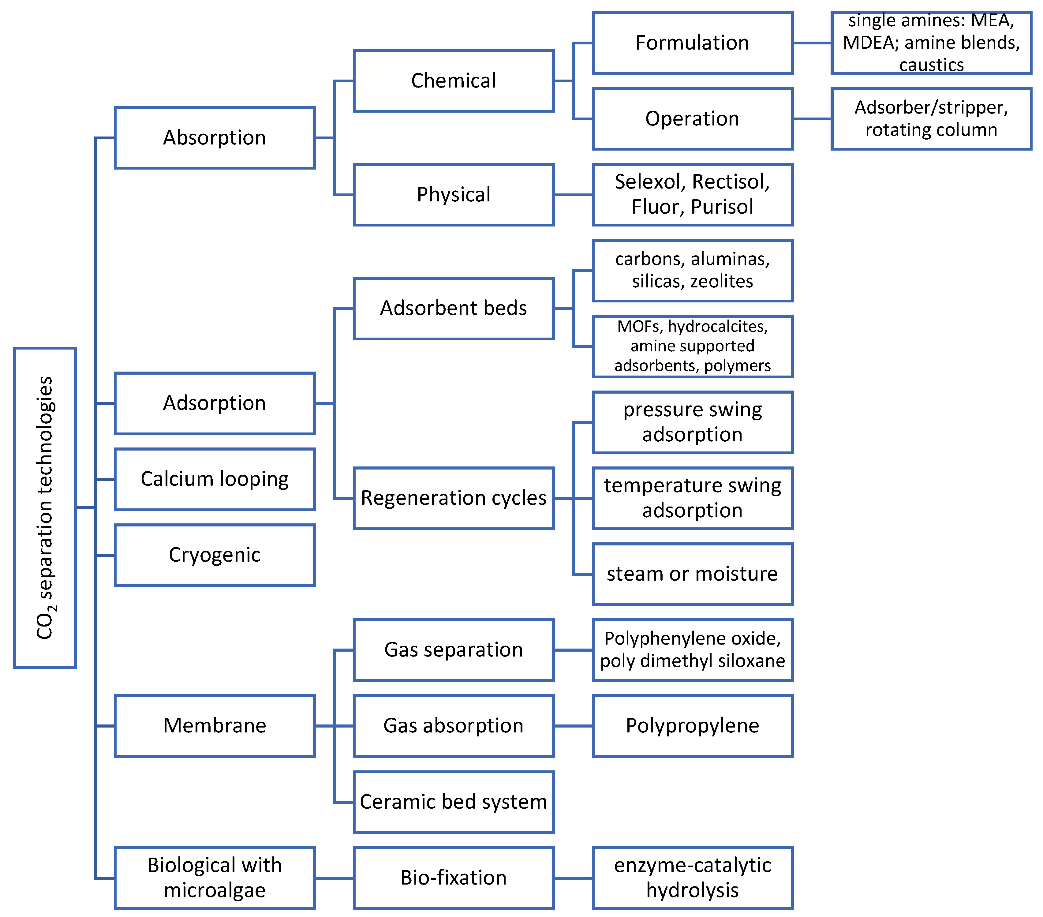
The continuous search for economic growth is causing the decline of natural resources, the detriment of air quality, and is fostering climate change. These effects have at last been taken seriously, which has led to new targets to reduce our impact on the planet. Achieving net zero emissions, as set by the UK, France, Denmark and New Zealand to be by 2050 and in Sweden by 2045, will need the exploitation of carbon capture, utilisation, and storage (CCUS) more than ever. This has been reaffirmed in the recent UK government plan for a green industrial revolution, which aims to make two CCUS industrial clusters operational by the mid-2020s and capture 10 Mt of carbon dioxide a year by 2030 [1]. Figure 1 shows the different CO2 separation technologies that are currently available. Carbon capture has focused on mature technologies, such as chemical absorption using amine-based solvents, but the large volumes of solvent that are used require significant thermal energy for regeneration. This shortcoming is promoting research on emerging technologies including membranes, calcium looping, catalysed sorbents, algae-based capture, direct air capture, and liquefaction [2], but most of these technologies face different technological challenges and are at different and/or lower technology readiness levels.
Low temperature CO2 capture technologies, often called cryogenic carbon capture, relies on phase change, thus separating the CO2 from the gas in the form of a liquid or solid [3]. The definition of ‘cryogenics’ refers more strictly to the processes that occur at temperatures below 120 K, e.g., in the condensation of nitrogen and oxygen, whilst above 120 K typically refers to conventional refrigeration; however, the term is often used to imply low temperature separation [4]. Thus, the review of cryogenics below 120 K is outside the scope of this work dedicated to CO2 applications, and they have been extensively reviewed for the liquefaction of natural gas [5] and air separation units (ASU) that use multi-column cryogenic distillation to generate oxygen, nitrogen and argon elsewhere [6]. The low temperature or cryogenic separation process has been less popular because of it is too expensive or energy intensive or because it has a restricted range of potential applications. This method offers various benefits such a high purity product, avoids the need for toxic chemicals, and can be applied to a range of CO2 concentrations. Thus, this work aims to critically assess the different cryogenic technical options for carbon capture, and in particular, presents its potential small- and large-scale applications in order to draw recommendations and future directions.
Novelty and Research Strategy
This work reviews peer-reviewed journal papers and other peer-reviewed sources such as reports, thesis dissertations, book chapters, and conference proceedings within a period from 2010 to May 2021. Scopus and Web of Science Several were used as recognised databases to access the resources. This study reviews the advances and opportunities that cryogenic carbon capture (CCC) offers to mitigate CO2 emissions and to its potential applications should the technology reach a commercialization stage. Table 1 presents the strategy for the literature search grouped by categories and by using the indicated keywords. It was found the largest publication activity was from Brigham Young University, Universiti Teknologi Petronas, and the University of Tsukuba. Any unrelated source was eliminated, leaving a total of 92 articles. A total of three review papers have previously covered some aspects of cryogenic carbon capture: (i) Berstad, Anantharaman and Nekså [3] presented a review of carbon capture methods and technologies, including low temperature methods with more emphasis for the treatment of oxy-derived flue gases by partial condensation or distillation; CO2 desublimation was briefly reviewed; (ii) Maqsood, Mullick, Ali, Kargupta and Ganguly [9] provided a clear distinction between conventional and emerging cryogenic CO2 separation technologies; and (iii) a more recent work from Song, Liu, Deng, Li and Kitamura [2] offered an updated review of CCC methods with particular emphasis on the treatment of fossil fuel combustion sources. However, in order to compete with more mature options, CCC would need to overcome challenges related to the availability of cold energy sources, capture costs, and impurities. Thus, this work explores applications for CCC beyond the treatment of coal-fired and/or natural gas sources. This paper reviews applications that best fit CCC systems for both small-scale applications such as biogas upgrading and onboard carbon capture as well as for large-scale applications such as blue hydrogen production.
2. Types of Systems for Cryogenic Carbon Capture
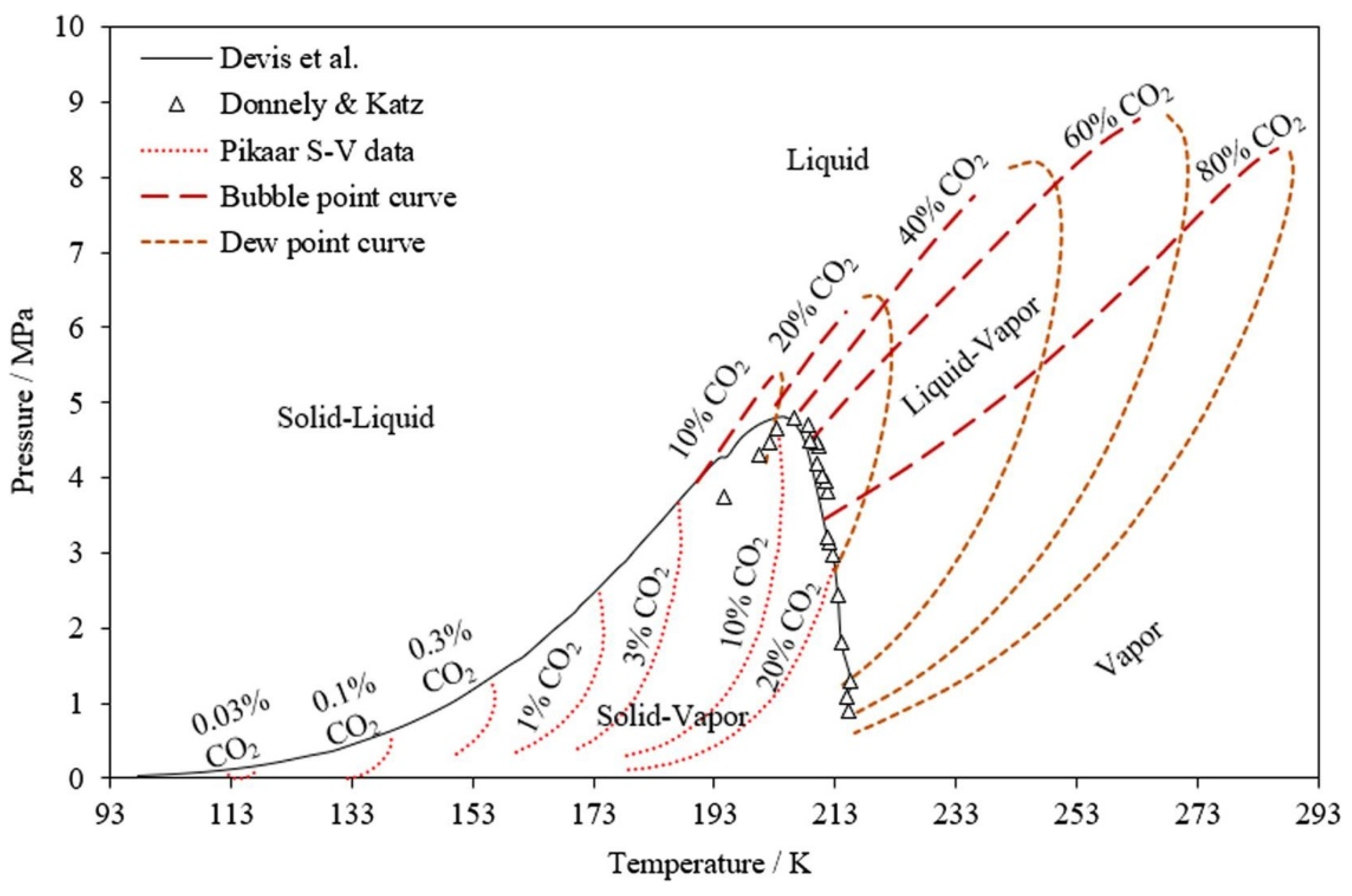
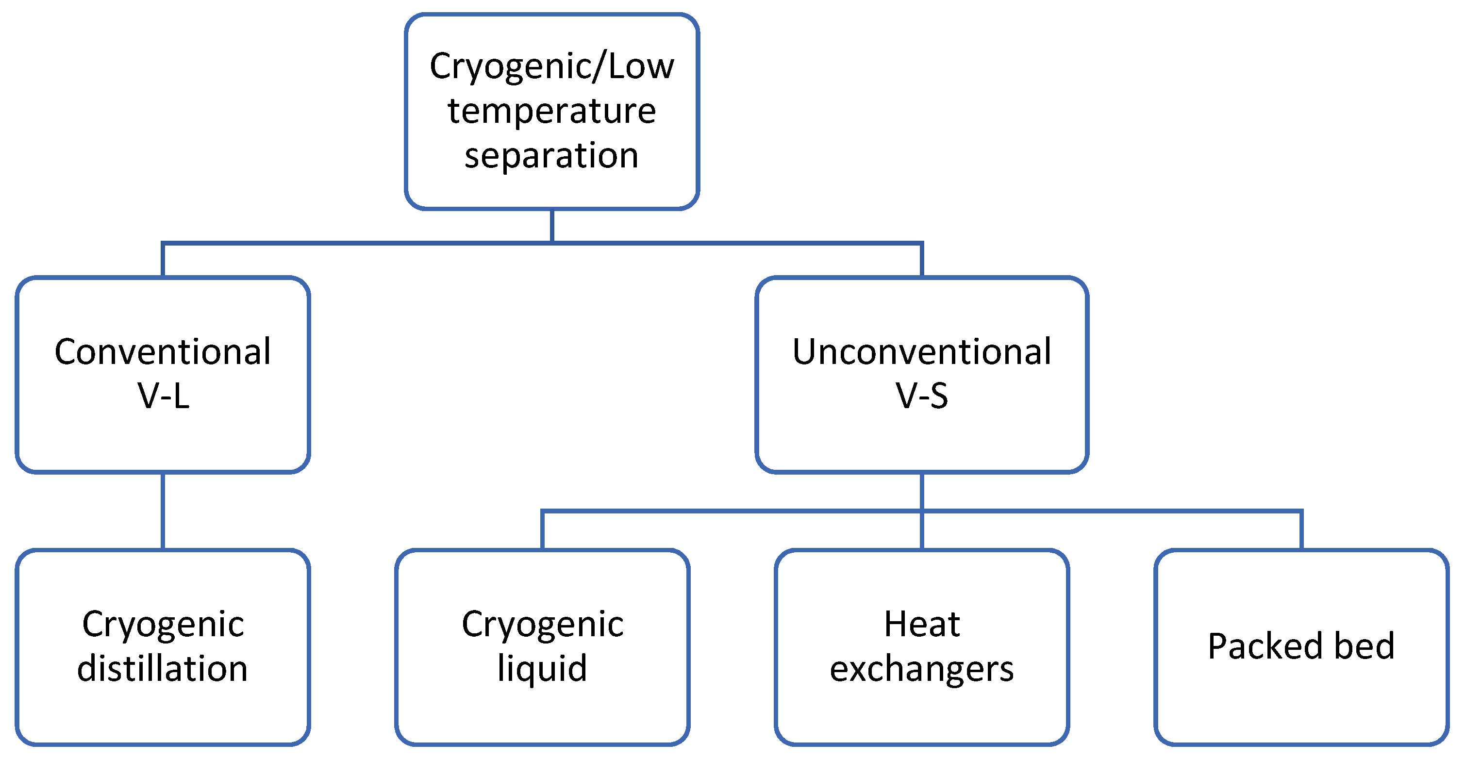
Cryogenic carbon capture involves a physical separation process based on the differences between the boiling points and the desublimation properties of the components in the gas mixture. Therefore, phase equilibria data are indispensable to define the pressure—the temperature conditions in which the CO2 in a mixture remains as a liquid, gas or solid. Figure 2 illustrates the dew and bubble curves and solid–vapour data for CO2–CH4 mixtures with varying CO2 content. The two regions provide two different types of cryogenic methods: liquid–vapour separation, or conventional cryogenic methods (above 193 K), and solid–vapour separation, or nonconventional methods (the region under the black solid curve) [2]. Figure 3 shows the existing and emerging methods for cryogenic carbon capture, which will be discussed further. There are also hybrid technologies not discussed here that can be found elsewhere [9]. Since cryogenic separation offers high CO2 recovery rates and purity levels, this technology is gaining considerable attention.
2.1. Conventional V-L Separation
Cryogenic distillation is a well-established technology that achieves separation based on the different boiling points of CO2 and the gas components in the mixture. This method has been used for natural gas purification, where the CO2 is removed in the liquid phase. However, it is an energy-intensive method due to the high pressure employed and the requirement that solid formation be avoided to protect equipment and prevent clogging. To avoid CO2 solidification, extractive distillation, or “Ryan Holmes” technology, makes use of heavier hydrocarbons (e.g., ethane), which increases the solubility of CO2 in the liquid phase, operating temperature, and relative volatility, facilitating separation [10].
Gas-to-liquid carbon dioxide separation is well recognized as the advanced technology for the purification and compression of CO2 captured in oxy-combustion. A CO2-rich flue gas derived from oxy-combustion is ideal for integration with a carbon dioxide purification unit (CPU) for low temperature CO2 separation. Previous work has evaluated CO2 removal in a two-stage compression at approximately 15 and 30 bar and by the partial condensation and separation of the resulting vapour and liquid phases [11]. The required purity and recovery are accomplished by the fine-tuning of the operating temperatures and pressures and the inclusion of additional flash separation stages to remove the lower boiling point O2/N2/Ar components [12]. For a high purity CO2 product for enhanced oil recovery (EOR) applications, in addition to the flash separation stages, a further stripping column is needed to reduce the oxygen content to 100 ppm [11]. This low temperature separation method is recommended for streams with a CO2 concentration higher than 50% to limit refrigeration and energy consumption. The other shortcoming is that a CPU requires expensive methods to reduce water content to trace levels to avoid plugging caused by ice, the formation of solid CO2 on the heat exchanger surface, and/or an increase in the pressure drop [13].
2.2. Unconventional V-S Separation
The relatively large energy requirements of conventional cryogenic distillation make vapour–solid (V–S) separation an attractive solution. A study that compared the two options found that for a gas mixture with a concentration of 70% vol. CO2, the energy requirement for a conventional extractive cryogenic distillation network was 1472 kJ/kg CO2, and the energy requirement for a cryogenic packed bed was 810 kJ/kg CO2 [14].
Low-temperature carbon capture based on solid–vapour equilibria takes advantage of solid formation, which is undesirable in cryogenic distillation and requires reaching temperatures at which CO2 will frost. Achieving desublimation conditions entails contact with a cold medium; therefore, different options to attain the cold conditions that are needed are presented here.
2.2.1. Heat Exchangers for Cryogenic Separation
Heat exchangers are key unit operations for cryogenic industrial applications, such as process cooling, the separation and distillation of gas mixtures, and liquefaction for transportation and storage. The overall energy performance of the system is mostly assessed based on the requirements of the compressors. Therefore, cryogenic heat exchangers are designed to operate with high effectiveness with relatively small temperature differences to compensate for the large heat transfer areas needed and high initial costs. This leads to high manufacturing and installation costs as well as the need for cost-effective heat exchangers to limit the range of the heat exchangers that could be used. Heat exchangers for cryogenic applications include coil-wound heat exchangers used in industrial air liquefaction; plate heat exchangers, including multi-stream plate fin heat exchangers (MPFHE); and regenerative heat exchangers, which are more compatible with energy storage technologies [15].
For the cryogenic separation of CO2 using heat exchangers, a system that employs three heat exchangers was developed [16]. The first heat exchanger precools the rich CO2 stream down to −100 °C, with a colder lean CO2 stream of −125 °C in a gas/gas brazed heat exchanger. The other two act as an intermittent frosting process to capture CO2 solids on the fins of the heat exchange at a temperature between −100 and −120 °C and as a CO2 defrosting process using a heating stream at −50 °C to recover liquid and gas CO2. Due to frost growth during the frosting step, the defrosting process is needed to maintain acceptable pressure losses on the gas-side circulation. Thus, a thermal swing process is employed, which switches between frosting and defrosting conditions, which can cause challenges for continuous operation. In addition, the CO2 frost layer on heat exchanger surface affects the heat transfer, requiring more cooling and thus reducing its efficiency.
Stirling Coolers
Song, Kitamura, Li and Ogasawara [17] proposed the use of Stirling coolers in a cryogenic CO2 capture system. The system makes use of three Stirling coolers (SC). The first one is used to precool the feed gas to condense moisture. The second SC is the freezing tower, where the CO2 freezes, and the third SC is used for cryogenic CO2 storage. The attained specific energy consumption with a CO2 recovery of 95% is estimated as 2.62 MJel/kg CO2 and is reduced to 1.37 MJel/kg CO2 with heat integration, including the capture and compression work [18]. Thus, this system suffers similar issues with the growth of the CO2 frost layer as the use of heat exchangers.
2.2.2. Cryogenic Liquids
As an alternative to heat exchangers, the flue gas containing CO2 can be directly contacted with a cryogenic liquid, causing the flue gas to form solid CO2 particles in a staged desublimating column. The CO2 that is dissolved in the contacting liquid will form a slurry, which then goes through filtration and will subsequently provide a CO2 pure product [19,20]. The contact liquid is used to provide cooling by direct contact whilst preventing CO2 from freezing on surfaces and to aid in the transport of frost CO2 as a slurry. Isopropane has been chosen based on holding low the vapour pressures need to be to minimise losses by evaporation [20]. Since solid CO2 is filtered, the contact liquid can be recycled with the aim of creating a closed loop, and only a slight loss of contact liquid is anticipated. The direct liquid–gas contact can be achieved through a bubbling column for pilot-scale applications, a spray tower for larger or full industrial-scale applications, or a fluidised bed column with the potential for large-scale application but that has not been tested yet [19]. Through modelling work, it an energy penalty of 0.74 MJel/kg CO2 with 90% CO2 capture was reported.
Cryogenic carbon capture with an external cooling loop (CCC-ECL) uses heat exchange to desublime CO2 frost. The flue gas first passes through a dryer that removes the water content from the flue gas, the dry flue gas then passes through a heat exchanger and is mixed with a contact liquid, where 99% of the CO2 is desublimed out of the gas phase. The heat exchanger cooling is supplied via an external cooling loop refrigerant. After the CO2 solid is separated from the gas stream and the contact liquid, the CO2 solid stream is pressurised to 70–80 bar. After this compression stage, the CO2 solid stream and the CO2 lean gas stream pass through a second heat exchanger, which provides energy recovery to the ECL refrigerant and melts the CO2 solid stream into a high pressure liquid stream [21,22]. The CCC-ECL process overcomes some of the limitations of heat exchangers, such as the reduction of the rate of heat transfer due to the CO2 frost layer formation on the heat exchanger surface. The solid handling is improved by forming a slurry of contact liquid with solid CO2; however, this process depends on the selection of the contact liquid, which should have a low vapor pressure to avoid loss via evaporation as well as not pose environmental or human harm.
2.2.3. Packed Beds
Packed beds filled with cold bed material have been used as a heat transfer surface for CO2 capture [14,23]. Cryogenically cooled nitrogen gas is fed into the packed bed to precool bed material as a cooling step. Once the precooling step is complete, the nitrogen cooling gas flow is stopped, and a simulated flue gas containing CO2 is fed into the packed column. When the flue gas containing CO2 is sufficiently cooled by the bed material, the CO2 desublimates onto the surface of the bed material to form a frost. The CO2 frost will continue to grow on the surface of the bed material until the bed material reaches saturation. When the bed material becomes saturated, the CO2 frost will begin to form on the fresh bed material that is further into the capture column. This leads to a frost front that advances through the packed column. The rate at which the frost front advances through the column is called the frost front velocity. The capture column is saturated with CO2 frost when the frost front advances through the capture column and requires a regeneration step to remove the CO2 frost from the packed bed. Tuinier et al. [24] performed a numerical study of three packed beds operating in parallel cycling between the capture, regeneration, and cooling steps to create a pseudo-continuous process. The cooling duty is dependent on the initial bed temperature and the concentration of CO2 in the flue gas but typically ranges between 1.2–2.6 MJel/kg CO2 [24].
Moving Packed Beds
Willson et al. [25] proposed the use of a moving packed bed of cold bed material to capture CO2 without using multiple packed beds operating in cycles. The moving packed bed captures CO2 frost on the surface of the bed material. Bed material is drawn out of the capture column using a screw conveyor and transported into a sublimation unit, the CO2 frost is sublimed and captured for later storage, and the bed material is recirculated into a bed precooler unit and back into the capture column. This operation prevents the excessive accumulation of CO2 frost within the capture column. The moving bed capture process has been experimentally demonstrated with proposed further work to integrate the cooling and regeneration steps into the moving bed, but this has not been tested yet [26].
The estimated specific energy of CO2 capture was calculated by Willson et al. for a number of different applications, the most effective application being biogas upgrading with a specific energy of 263 kWh/tonne CO2 (0.95 MJ/kg CO2) [25].
2.2.4. Other Methods
Compressed Flue Gas
Cryogenic carbon capture with compressed flue gas (CCC-CFG) moderately compresses the flue gas to 5–7 bar before heat exchange and expands the flue gas after heat exchange to desublime CO2 frost [27]. This process uses a dryer to remove water content from the flue gas and then uses a heat exchanger to desublime CO2. Similar to the CCC-ECL process, the heat exchanger recovers energy using the pressurised solid CO2 stream, which cools the incoming flue gas, and the solid CO2 melts. This heat exchange step sufficiently cools the flue gas to desublime approximately 75% of CO2 out of the gas phase. After the expansion of the compressed flue gas, 99% of the CO2 is separated out of the gas phase.
Table 2 compares different CCC technologies including other carbon capture technologies such as absorption, adsorption, and membranes. It is shown here that CCC provides a competitive energy duty compared to a range of available CCS technologies, whilst membrane separation provides the most attractive energy duty through the use of vacuum configurations as the driving force [28]. CCC technologies are still in various stages of technological readiness level (TRL) and require further development and large-scale demonstrations to increase confidence in the technology.
CCC is not a universally applicable technology; however, there are feasible applications where cryogenic separation is advantageous compared to other technologies. The most feasible applications where cryogenic separation is advantageous are discussed next.
3. Feasible Applications for Cryogenic Separation
3.1. Small-Scale Applications
3.1.1. Shipping Decarbonisation
The recognition that the maritime sector emits about 3.1% of global GHG emissions has helped the International Maritime Organization (IMO) commit to reduce CO2 emissions from international shipping by at least 40% by 2030 and by at least 50% by 2050 compared to 2008 emissions [31]. Among the different options to reduce the emissions of GHGs from the shipping sector, e.g., fuel switching to LNG or alternative fuels such as biofuels, methanol, and hydrogen, have been proposed [32]. Balcombe, Brierley, Lewis, Skatvedt, Speirs, Hawkes and Staffell [32] concluded that decarbonisation using LNG will require a combination of efficiency measures to achieve the target of a 50% reduction of GHG emissions, and bio-based fuels that struggle to prove sustainable source availability will rely more on efficiency measures to reduce their consumption. Thus, exhaust gas treatment via carbon capture offers advantages to avoid changes in engines.
An onboard carbon capture and storage (OCCS) system is a solution to treat exhaust gases emitted from the internal combustion engines on board of ships. The stored CO2 can be unloaded at ports and is then stored underground or undergoes methanation [33].
OCCS offers an option that avoids changes to or the replacement of ship engines. However, most of the literature on carbon capture for shipping applications is related to chemical adsorption using amine-based solvents. For example, Feenstra, Monteiro, van den Akker, Abu-Zahra, Gilling and Goetheer [34] proposed solvent-based carbon capture in diesel and LNG-fuelled vessels (1280 kW dual fuel Wärtsilä 8L20DF and 3000 kW Wärtsilä 6L34DF). They used MEA as a reference case, which was evaluated against 30 wt.% aqueous piperazine (PZ). PZ showed lower costs compared to MEA cases due to the higher pressure used in the desorption process and the consequently lower CO2 compression costs. They concluded after an evaluation of equipment weight with stored CO2 that the carbon capture unit could be fit onboard the ship following space reconfiguration. Awoyomi, Patchigolla and Anthony [35] proposed scrubbing using aqueous ammonia for the simultaneous CO2 capture and the removal of SO2 from the flue gas from a 10,800 kW Wärtsilä 9L46F marine diesel engine. Through waste heat recovery, they found that a 70% CO2 capture rate at 85% load is achievable. They showed that a 75% carbon capture rate is possible to recover heat using the WHRS (waste heat recovery system) for use in the reboiler (ammonia requires less heat for regeneration than MEA), but 12.88% more fuel was needed to deliver the same power output of 8.7 MWe at an 85% load due to the power requirements for CO2 capture and compression for storage.
Thus, the potential for OCCS using chemical solvents has encouraged the exploration of cryogenic carbon capture. As an example, the advanced cryogenic carbon capture (A3C) process has been evaluated for shipping applications. Two case studies were assessed: an LNG fuelled pure car and truck carrier (12,614 kW dual-fuel 7S60ME-C10.5-GI two stroke diesel engine) and a hybrid diesel (1200 kW engine that burns marine gas oil, MGO)-electric/battery ferry. The study found that the integration of the A3C process into new built or retrofitted vessels is feasible. However, the A3C process showed an impact on the total fuel consumption, which increased by 17% for LNG and by 24% for MGO when capturing 90% of carbon emissions from the main and the auxiliary engines and an additional load on the vessel by the liquid CO2 storage tanks. The report concludes that the cost of the A3C process for shipping could be up to 50% lower than the conversion of vessels to use zero carbon fuels [36]. More recently, Chart Industries Inc. acquired Sustainable Energy Solutions (SES), and they have signed an agreement with the Norwegian company TECO 2030 to jointly develop an OCCS solution using Cryogenic Carbon Capture TM (CCC) technology [37].
In the UK context, CCC could aid in the decarbonisation of marine transport to reach the targets set in the UK Maritime 2050 strategy for 50% reduction of GHG emissions by 2050 [38], whilst avoiding major design changes needed in order to switch fuel sources to ammonia or hydrogen as proposed in the Clean Maritime Plan [39]. This is an important sector in the UK economy since transport by sea involves around 95% of imports and exports, 25% of the energy supply, and 48% of food supply.
3.1.2. Biogas Upgrading
Upgrading biogas from waste such as manure [40], sewage sludge, or municipal waste to a higher methane content to produce ‘biomethane’ is of interest in countries with schemes that support its use as a vehicle fuel or for injection into the natural gas grid. Europe is the world’s leading producer of biomethane, with 367 biomethane anaerobic digestion (AD) plants with a total upgrading capacity of 310,000 m3/h of raw biogas in 2014 [41].
Water scrubbing/absorption and amine-based chemical absorption are the most common upgrading technologies. Cryogenic/low-temperature upgrading technologies are still under development; however, they deliver a high methane purity with minimal methane loss (<1%) and a high purity captured CO2 that usually shows up to 98% purity [42]. Though cryogenic distillation is the preferred method [42,43,44], it has been reported to consume a total specific energy of 1.79 MJ/kg CO2 (0.35 kWh/Nm3 of raw biogas) to produce biomethane at a 95.56% capture rate. Most efforts have focused towards the avoidance of dry ice formation caused by CO2 cryogenic separation due to potential operation problems caused by the blockage of pipes or other equipment [42]. However, a liquefaction process offers opportunities to deliver liquid biomethane (LBM) by freezing CO2 with a reduced energy consumption of 0.65 kWh/Nm3 of processed raw biogas, which is equivalent to the 5.2 MJ/kg of LBM that is produced [45].
Biogas composition mainly consists of methane and CO2, but it also contains trace contaminants such as H2S, organics, and siloxanes. The drying and precooling stages of CCC systems provide the conditions for the removal of benzene, whilst siloxanes are fully removed simultaneously during the CO2 removal step [46]. Alternatively to biogas upgrading, biogas could be employed directly in micro gas turbines, and the exhaust gases could be treated by post-combustion carbon capture technologies such as cryogenic carbon capture, which could lead to negative net emissions [47].
3.2. Large-Scale Applications
3.2.1. Blue Hydrogen Production
For low-carbon hydrogen production using fossil fuels, CCS technology is essential to produce the so-called ‘blue’ hydrogen in order to minimise CO2 emissions. High-purity hydrogen of 90–98% can be attained in large-scale hydrogen production plants through cryogenic distillation with hydrogen recovery of 96% [48]. The principle used here is based on the partial condensation of the impurities in the off-gas generated during hydrogen production at low temperatures. The steam methane reformer or refinery off-gas is a mixture of CH4, CO2, CO, and other light hydrocarbons whose boiling points are relatively higher than that of hydrogen and therefore condense when the temperature is reduced significantly. Depending on the optimal operating conditions of the production plant, various refrigeration methods can be employed.
Joule–Thomson expansion of condensed hydrocarbon has been reportedly applied for refinery plant off-gas to meet the refrigeration requirement for cryogenic separation at an optimal feed pressure, gas rate, and hydrogen content of 2.8 MPa, 5000 m3/h, and less than 80%, respectively [49]. Aasadnia, Mehrpooya and Ghorbani [50] used a Joule–Brayton propane unit and an auxiliary nitrogen unit to provide cold energy for the cryogenic separation of hydrogen from a feed gas containing nitrogen, methane, ethane, propane, and benzene in order to produce a high-purity hydrogen. The two refrigeration units, the Joule–Brayton propane and the nitrogen units, delivered refrigeration at −155 °C and −40 °C, respectively. It was observed that the amount of hydrogen in the feed gas has an effect on the energy demand of the process in terms of energy required for compression and liquefying the nitrogen refrigerant. A 68% increase in the mole fraction of hydrogen in the feed gas inversely led to a 38% reduction in the energy consumed in the process. An increased pressure of the hydrogen-rich stream was reported to have increased the energy consumed by the propane unit and, consequently, the specific energy due to the resulting high temperature of the stream. There was also a rise in the cryogenic nitrogen that was required and an accompanying reduction in hydrogen recovery rate [50].
Conventional cryogenic distillation is a matured separation technology for hydrogen production just like pressure swing adsorption (PSA) technology. Although it benefits from higher hydrogen recovery compared to the PSA technology predominantly used in hydrogen production plants, its major drawback is the high energy demand required for hydrogen separation and purification leading to increased costs [48,51,52]. In addition, an initial step is necessary to remove water, CO, CO2, and H2S (if present) from the feed gas in order to prevent component holdup at low temperatures [53]. This has consequently led to a decline in the adoption of cryogenic distillation as a separation technology to purify hydrogen from reformer or refinery off-gas.
Recent efforts have progressed towards the combination of conventional cryogenic distillation with other hydrogen separation technologies such as PSA and membranes to improve the capture of CO2 generated during hydrogen production. Due to the increased energy demand required to obtain high-purity hydrogen from the cryogenic separation method, Agrawal, Auvil, DiMartino, Choe and Hopkins [54] proposed a combined membrane/cryogenic hybrid system. Cryogenic separation can improve hydrogen recovery, and the membrane system can achieve high-purity hydrogen when both systems are combined effectively. With refrigeration supplied by liquid nitrogen, a thermodynamic analysis of the hybrid cryogenic/membrane system was performed. It was observed that an increased concentration of hydrogen in the feed gas directly impacted the thermodynamic efficiency of the cryogenic process, with efficiency dropping from approximately 35% to 20% to produce hydrogen streams of purities of 70% and 96.5%, respectively. The power requirement reported for the hybrid system was approximately 65% of that needed if the whole system were a completely cryogenic process. Although the hybrid system requires an additional membrane separation unit, the refrigeration for the cryogenic part has less refrigeration demand compared to an all-cryogenic system, thereby resulting in a lower capital cost for the hybrid system [54].
In their work, Kurokawa, Shirasaki and Yasuda [55] demonstrated a CO2 capture caused by cryogenic separation using a high hydrogen production efficiency membrane reactor off-gas, which produces hydrogen from natural gas, and 90% CO2 was captured. The efficiency of the combined system was reported to be 78.6% with CO2 emissions reduced by 50% compared to conventional technology. A sensitivity analysis of the system conducted using a process simulator showed that the efficiency of the system falls with the decreasing temperature of the gas–liquid separator due to the high energy needed for the refrigeration unit to lower the phase separator temperature and subsequently improve the rate of CO2 recovery from the off-gas.
Lin, He, Sun, Kniep, Ng, Baker and Merkel [56] evaluated and conducted a techno-economic analysis on a membrane/cryogenic hybrid system used for hydrogen production and CO2 capture. A total of three hydrogen production methods were considered: coal oxy-fired GE gasifier in an integrated gasification combined cycle (IGCC), a methane reformer/PSA process, and a coal air-blown IGCC power plant. The feed gas for the hybrid unit adopted for hydrogen purification and CO2 capture was the PSA off-gas generated by the methane reformer/PSA process and the syngas produced from both IGCC power plants. It was reported that the performance of the hybrid system depends on the CO2 capture target, process stream conditions, and membrane properties. In the methane reforming plant, it was revealed that the concentration of separated CO2 increases at a faster rate than the compressor when the CO2 capture rate is increased, resulting in a rise in the cost of refrigeration. The optimum capture rate was disclosed to be 80%, above which there is a substantial increase in the power consumed and, subsequently, the cost of the produced CO2 liquid. However, a high concentration of CO2 in PSA off-gas as well as high CO2/H2 membrane selectivity was shown to have made cryogenic separation easier, leading to lower capital cost.
Similarly, Kim, Berstad, Anantharaman, Straus, Peters and Gundersen [57] optimised and compared three refrigeration methods for the cryogenic separation of CO2 from a membrane reactor off-gas (retentate) containing hydrogen, CO, CO2, and CH4. The three separate cryogenic systems that use two-component refrigerants (composed of propane cycle and ethane cycle), single mixed refrigerant (comprising a mixture of methane, ethane, propane and butane), and Joule–Thomson expansion to liquify the reactor off-gas were simulated in Aspen HYSYS. Results indicated that the single mixed refrigerant design had the largest energy efficiency, while the Joules–Thomson system gave the highest power consumption due to the compression work required to increase the pressure of the retentate. It was, however, concluded that the Joule–Thomson system can be applied for retentate gas lean in CO2, while the two-component refrigerants system can be considered for CO2 rich gas retentate.
A hybrid system is already being demonstrated on an industrial scale. For instance, Air Liquide’s CRYOCAP™ hydrogen technology has already been deployed on a small industrial scale and uses cryogenic technology and membranes to purify the CO2 present in PSA off-gas in a conventional steam methane reforming plant. In this concept, the reformer product stream is sent to the PSA to first separate the hydrogen. The PSA off-gas is then directed to the combined membrane-cryogenic distillation unit to separate and purify CO2 present in the PSA off-gas. There was a reported increase in hydrogen recovery, with more than 97% of CO2 from the syngas being captured [58,59]. In addition, ongoing research to perfect CO2 removal from flue gas makes use of their hybrid cryogenic technology, which combines PSA to produce a pre-concentrated CO2 stream and cryogenic method to further separate the concentrated CO2 stream from lighter gases [60]. When compared to amine technologies, CRYOCAP™ FG, for concentrated flue gases displayed a high CO2 capture rate of 90%, whereas the amine-based CO2 capture technology exhibited a 69–74% CO2 capture. Although demonstrated to be more economical than amine-based separation, this PSA-Cryogenic hybrid technology is not yet demonstrated at industrial scale and is rated at TRL 6.
In more recent research considering unconventional cryogenic liquid technology, Yurata and his team [61] illustrated the feasibility of de-sublimating carbon dioxide before hydrogen liquefaction for CO2-H2 separation. In their approach, two de-sublimation columns were used simultaneously to subject the feed gas to a cold environment, where CO2 solidifies on the internal surface and subsequent heating to release CO2 and H2. Thereafter, the separate gas streams were liquified for storage and transportation. The energy demand of this process was compared toH2-CO2 separation technologies (membrane, PSA and MEA absorption) integrated with a liquefaction step downstream. It was proven that the de-sublimation method showed the lowest energy requirement. However, this process is not yet as widespread as the conventional cryogenic distillation.
3.2.2. Direct Air Capture (DAC)
The removal of CO2 from air was first commercialised in the 1950s as a means to pre-treat the air before undergoing cryogenic air separation [62]. In the late 1990s, CO2 removal from air (400 ppm CO2), now known as direct air capture (DAC), was explored to mitigate climate change, particularly from dispersed CO2 emitters or relatively small emitters [63]. DAC systems mostly involve solid sorbents or aqueous solutions. Aqueous solvents benefit from continuous operation but require costly regeneration systems. Carbon Engineering is one of the companies developing an aqueous DAC process; in their process, CO2 is first removed using a KOH solution, and the CO3−2 is then precipitated with Ca+2 to form CaCO3, which is then calcined to release the CO2 [62].
Direct air capture could also be achieved by using cryogenic separation via CO2 desublimation. Baxter, Baxter and Burt [27] have assessed the cryogenic potential on various CO2 compositions representing different sources of CO2. They reported that for a gas stream with a 14% CO2 content on a dry basis, a temperature of approximately −119 °C would be required, whilst a much lower CO2 content of 1% would only decrease the temperature to −136 °C for a conservative 90% CO2 capture efficiency. If their reported temperatures are extrapolated to 400 ppm CO2, a lower temperature of around −157 °C would be required. Thus, the cooling that is needed is achievable and less than what is necessary in air separation units (e.g., temperatures between −183 °C and −196 °C).
4. Challenges for Commercialisation
4.1. Technology Readiness Level (TRL)
Cryogenic carbon capture is in the early stages of development. For example, Stirling coolers have only been tested at laboratory scale using solely CO2/N2 binary gas mixtures [17,64]. This system needs to be scale up to pilot or large-scale applications and be applied to different industrial CO2 emissions (such as power plants, cement, and steel, which represent different CO2 concentrations and the inclusion of impurities).
PMW Technology has demonstrated the capture step of the moving packed bed technology called A3C. The current technological readiness level of the A3C process is TRL 3, with a capture efficiency of 93% and higher [26]. Further development of the A3C process is expected to focus on the integration of the bed cooler, the capture column, and the bed sublimer into a combined continuous system.
Sustainable Energy Solutions (SES) has developed the Cryogenic Carbon Capture ™ (CCC) technology that claims to reduce CO2 emissions from fossil-fuelled power plants by 95–99% [65]. SES has developed a direct-contact phase-change (DCPC) dryer for the simultaneous cooling and drying of the feed gas. The DCPC has been tested with a lithium chloride/water brine and a potassium acetate/water solution. For further cooling, they have used an ethanol/water solution or a methanol/water solution without freezing at the low temperatures that are needed [22]. More recently, SES has tested the CCC TM pilot demonstration unit to capture at least 95% of CO2 from a slipstream of 1 tonne per day (TPD) at the Cementos Argos’ Roberta cement plant near Calera, Alabama and at the PacifiCorp Hunter coal-fired power plant near Castle Dale, Utah for nine months [65,66], which moves the technology to at least TRL 5. The company has plans to scale up the CCC-ECL process to a small commercial unit of 20–100 TPD after Chart Industries has acquired SES.
A technology that makes use of heat exchangers for the frosting and defrosting of CO2 followed by biomethane liquefaction is being commercialised by Cryo Pur. The process upgrades biogas into LBM (or bio-LNG). Their first commercial unit was installed in 2017 at Greenville Energy in Northern Ireland and operates at 3 tonnes of bio-LNG per day (i.e., treating 300 Nm3/h raw biogas) [67]. Thus, this is the most advanced CCC process, with a TRL of at least 6.
4.2. Competing Technologies
It is out of the scope of this work to review all of the other alternative carbon capture methods and separation processes shown in Figure 1. Others have published in-depth reviews that can be found in [68,69,70]. Table 3 compares cryogenic carbon capture against more mature technologies, such as absorption and adsorption, highlighting their benefits and disadvantages.
In terms of hydrogen production, a comprehensive work that has gathered and compared the cost of hydrogen and capital costs for H2 production found that the costs of SMR with CCS are comparable or even lower than alternative methods such as gasification with and without CCS, nuclear thermolysis, and electrolysis [71]. All technological options are needed to reach the ambition target of net zero emissions by 2050, and CCS is indeed essential for the reduction of industrial emissions and hydrogen production.
Another emerging technology is sorption enhanced steam methane reforming (SE-SMR), a process intensification of steam methane reforming, which involves the in situ removal of CO2 produced during hydrogen production from a hydrocarbon source such as natural gas in a single reactor [72]. CO2 separation is usually done using a high-temperature solid sorbent such as calcium oxide (CaO) which can be regenerated by temperature swing or pressure swing to produce pure CO2 stream [73]. With the sorbent capture cost going as low as USD 9– 11 per tonne of CO2 captured, a pure hydrogen stream of up to 99% can be attained [74,75]. This technology is already being demonstrated at the pilot stage. The BioZEG pilot plant developed by ZEG Power AS employs the concept of SE-SMR to produce hydrogen from hydrocarbon fuels. The plant, which integrates solid fuel oxide technology (20 kWe) with hydrogen production (30 kWH), is reported to have a potential of 100% CO2 capture and 80% energy efficiency [76]. Hynor Lillestrøm have deployed a small-scale hydrogen production technology that currently integrates the sorption enhanced process for hydrogen production at their hydrogen station. The SER prototype capable of producing 12.5 Nm3/h hydrogen from biogas at high carbon capture is currently operated by IFE Hynor in their lab [77]. The Gas Technology Institute (GTI) has successfully demonstrated a 71 kWth integrated hydrogen production and carbon capture plant in the US. The facility was reported to achieve hydrogen purity of ~92% and 90% CO2 capture [78]. For information on the wide range of hydrogen production technologies available and under development, please refer to other reviews [79,80,81].
4.3. Incentives
The need for CCS Research, Development, and Demonstration (RD&D) policy is key, particularly for emerging technologies such as CCC systems. In the US, legislation in the Section 45Q tax credit (45Q) for carbon oxide sequestration defined the value of USD 35/tCO2 for EOR and non-EOR COx use and USD 50/tCO2 for COx secure geologic storage in 2018. More recently, the CCUS Tax Credit Amendments Act rised the 45Q credit value from USD 50 to USD 120 per metric ton for DAC plants that securely store CO2 in saline geologic formations and from USD 35 to USD 75/tonne for DAC facilities with CO2 storage in oil and gas fields [88].
Although the Netherlands is committed to reduce 14 Mton per year of CO2 by 2030 and recognises the substantial role of CCS to achieve their target, the country has capped CCS efforts to 7.2 Mton of CO2 capture to keep CCS as a transition technology particularly for difficult industries (e.g., cement). Thus, after 2035, there will be no more subsidies for fossil fuels, with a maximum subsidy of EUR 63/tonne of CO2 for CCS [89]. The company Carbon Collectors proposes collecting CO2 at customer site and then transporting it by ship to the nearest CO2 storage location [90].
For DAC, current studies have reported costs between USD 124 and USD 325 per metric tonne of CO2 removed from the atmosphere for the first million tons of installed capacity. The costs exclude CO2 compression and storage. For the US, support and policies for DAC are predicted to drop levelized costs through technological improvements, economies of scale, and mass production to between USD 85 and USD 261 per metric ton of CO2 at 7–9 MMt of capture capacity by 2030 [91].
4.4. Challenges and Perspectives
CCS technologies are key to achieving industrial decarbonisation and meet net zero carbon targets. Current CCS technologies have reported varying costs depending on the application, e.g., USD 40–60/tonne CO2 for the power sector and USD 200/tonne CO2 for the cement sector [92], and advances should decrease costs as CCS is more intensely deployed. It has been estimated that the current annual carbon capture of 40 Mt of CO2, with 26 operating CCS facilities, should increase to 5.6 Gt by 2050 to decarbonise not only the power sector but also hard to abate industries such as steel, cement, chemical industries [93]. The grand capacity that would be needed would create opportunities for projects of different scales and not just for foundation industries—one of the largest UK emitters with 50 Mt of CO2 per year.
Due to the benefits of economies of scale, many countries, including the UK, USA, Canada, and Norway are creating hubs and clusters of concentrated industrial regions where shared compression, dehydration, transport, and storage will aid in decreasing unit costs and risks by synergies from multiple customers and suppliers of CCS networks [93].
For small-scale emitters, such as small enterprises or ships, novel and compact solutions are needed to minimise costs and space requirements. Cryogenic carbon capture could offer such solutions. In addition, CCC employed to upgrade biogas provides a means for negative emissions, and this application is more relevant when liquified biomethane and/or CO2 are the desired products. The amount of CO2 captured is suitable for decentralised solutions that are distant to CCS clusters as well as for CO2 use (CCU), e.g., for the synthesis of chemicals and production of building materials.
In order to assess the environmental effects of introducing CCS/CCU technologies, life cycle assessment (LCA) is a well-established tool for evaluating their impacts. So far, LCA for chemical absorption, oxy-combustion, chemical and calcium looping, and pre-combustion have been reported [94]. Thus, it is evident that emerging CCC technologies need LCA studies to be conducted without delay to support their relevance as low carbon solutions.
5. Conclusions
Carbon capture and storage is a technological option needed for the transition to the full elimination of fossil fuels and for the removal of carbon dioxide emissions for industries whose processes emit CO2. This review specifically covered cryogenic carbon capture (CCC) due to its benefits as a physical separation method. Different CCC methods that are mostly under development were presented, including their current challenges in deterring their commercialisation. It also offers an appraisal for selected feasible small- and large-scale CCC applications, including blue hydrogen production and direct air capture. This work provides an overview of the current status of CCC systems, including their technological readiness for CCC deployment and acknowledges competing technologies.
Author Contributions
C.F.-P.: conceptualization, writing—original draft preparation, writing—review and editing, funding acquisition; D.C. and C.U.: writing—original draft preparation, writing—review and editing. All authors have read and agreed to the published version of the manuscript.
Funding
C Font Palma thanks the fellowship supported by the Royal Academy of Engineering under the Leverhulme Trust Research Fellowship scheme (LTRF1920\16\18).
Institutional Review Board Statement
Not applicable.
Informed Consent Statement
Not applicable.
Data Availability Statement
All collected data are presented in the manuscript.
Conflicts of Interest
The authors declare no conflict of interest. The funders had no role in the design of the study; in the collection, analyses, or interpretation of data; in the writing of the manuscript, or in the decision to publish the results.
References
- BEIS. The Ten Point Plan for a Green Industrial Revolution—Building Back Better, Supporting Green Jobs, and Accelerating Our Path to Net Zero; HM Government: London, UK, 2020.
- Song, C.; Liu, Q.; Deng, S.; Li, H.; Kitamura, Y. Cryogenic-based CO2 capture technologies: State-of-the-art developments and current challenges. Renew. Sustain. Energy Rev. 2019, 101, 265–278. [Google Scholar] [CrossRef]
- Berstad, D.; Anantharaman, R.; Nekså, P. Low-temperature CO2 capture technologies—Applications and potential. Int. J. Refrig. 2013, 36, 1403–1416. [Google Scholar] [CrossRef]
- Timmerhaus, K.D.; Reed, R.P. Cryogenic Engineering: Fifty Years of Progress; Springer: Berlin/Heidelberg, Germany, 2007. [Google Scholar] [CrossRef]
- Kanbur, B.B.; Xiang, L.; Dubey, S.; Choo, F.H.; Duan, F. Cold utilization systems of LNG: A review. Renew. Sustain. Energy Rev. 2017, 79, 1171–1188. [Google Scholar] [CrossRef]
- Smith, A.R.; Klosek, J. A review of air separation technologies and their integration with energy conversion processes. Fuel Process. Technol. 2001, 70, 115–134. [Google Scholar] [CrossRef]
- Babar, M.; Bustam, M.A.; Ali, A.; Shah Maulud, A.; Shafiq, U.; Mukhtar, A.; Shah, S.N.; Maqsood, K.; Mellon, N.; Shariff, A.M. Thermodynamic data for cryogenic carbon dioxide capture from natural gas: A review. Cryogenics 2019, 102, 85–104. [Google Scholar] [CrossRef]
- Ben-Mansour, R.; Habib, M.A.; Bamidele, O.E.; Basha, M.; Qasem, N.A.A.; Peedikakkal, A.; Laoui, T.; Ali, M. Carbon capture by physical adsorption: Materials, experimental investigations and numerical modeling and simulations—A review. Appl. Energy 2016, 161, 225–255. [Google Scholar] [CrossRef]
- Maqsood, K.; Mullick, A.; Ali, A.; Kargupta, K.; Ganguly, S. Cryogenic carbon dioxide separation from natural gas: A review based on conventional and novel emerging technologies. Rev. Chem. Eng. 2014, 30, 453. [Google Scholar] [CrossRef]
- Holmes, A.S.; Price, B.C.; Ryan, J.M.; Styring, R.E. Pilot tests prove out cryogenic acid-gas/hydrocarbon separation processes. Oil Gas. J. 1983, 81, 85–86. [Google Scholar]
- Font-Palma, C.; Errey, O.; Corden, C.; Chalmers, H.; Lucquiaud, M.; Sanchez del Rio, M.; Jackson, S.; Medcalf, D.; Livesey, B.; Gibbins, J.; et al. Integrated oxyfuel power plant with improved CO2 separation and compression technology for EOR application. Process. Saf. Environ. Prot. 2016, 103, 455–465. [Google Scholar] [CrossRef] [Green Version]
- Besong, M.T.; Maroto-Valer, M.M.; Finn, A.J. Study of design parameters affecting the performance of CO2 purification units in oxy-fuel combustion. Int. J. Greenh. Gas. Control. 2013, 12, 441–449. [Google Scholar] [CrossRef]
- Mondal, M.K.; Balsora, H.K.; Varshney, P. Progress and trends in CO2 capture/separation technologies: A review. Energy 2012, 46, 431–441. [Google Scholar] [CrossRef]
- Ali, A.; Maqsood, K.; Syahera, N.; Shariff, A.B.M.; Ganguly, S. Energy Minimization in Cryogenic Packed Beds during Purification of Natural Gas with High CO2 Content. Chem. Eng. Technol. 2014, 37, 1675–1685. [Google Scholar] [CrossRef]
- Popov, D.; Fikiin, K.; Stankov, B.; Alvarez, G.; Youbi-Idrissi, M.; Damas, A.; Evans, J.; Brown, T. Cryogenic heat exchangers for process cooling and renewable energy storage: A review. Appl. Therm. Eng. 2019, 153, 275–290. [Google Scholar] [CrossRef]
- Pan, X.; Clodic, D.; Toubassy, J. CO2 capture by antisublimation process and its technical economic analysis. Greenh. Gases Sci. Technol. 2013, 3, 8–20. [Google Scholar] [CrossRef]
- Song, C.-F.; Kitamura, Y.; Li, S.-H.; Ogasawara, K. Design of a cryogenic CO2 capture system based on Stirling coolers. Int. J. Greenh. Gas. Control. 2012, 7, 107–114. [Google Scholar] [CrossRef] [Green Version]
- Song, C.; Liu, Q.; Ji, N.; Deng, S.; Zhao, J.; Kitamura, Y. Advanced cryogenic CO2 capture process based on Stirling coolers by heat integration. Appl. Therm. Eng. 2017, 114, 887–895. [Google Scholar] [CrossRef]
- Jensen, M.J.; Russell, C.S.; Bergeson, D.; Hoeger, C.D.; Frankman, D.J.; Bence, C.S.; Baxter, L.L. Prediction and validation of external cooling loop cryogenic carbon capture (CCC-ECL) for full-scale coal-fired power plant retrofit. Int. J. Greenh. Gas. Con. 2015, 42, 200–212. [Google Scholar] [CrossRef] [Green Version]
- Fazlollahi, F.; Saeidi, S.; Safdari, M.-S.; Sarkari, M.; Klemeš, J.J.; Baxter, L.L. Effect of Operating Conditions on Cryogenic Carbon Dioxide Removal. Energy Technol. 2017, 5, 1588–1598. [Google Scholar] [CrossRef]
- Baxter, L.; Lang, D. Cryogenic Carbon Capture Development; FE0028697; National Energy Technology Laboratory: Pittsburgh, PA, USA, 2016. [Google Scholar]
- Baxter, L.L.; Baxter, A.; Bever, E.; Burt, S.; Chamberlain, S.; Frankman, D.; Hoeger, C.; Mansfield, E.; Parkinson, D.; Sayre, A.; et al. Cryogenic Carbon Capture Development; National Energy Technology Laboratory: Pittsburgh, PA, USA, 2019. [Google Scholar]
- Tuinier, M.J.; Annaland, M.V.; Kramer, G.J.; Kuipers, J.A.M. Cryogenic CO2 capture using dynamically operated packed beds. Chem. Eng. Sci. 2010, 65, 114–119. [Google Scholar] [CrossRef]
- Tuinier, M.J.; Annaland, M.V.; Kuipers, J.A.M. A novel process for cryogenic CO2 capture using dynamically operated packed beds-An experimental and numerical study. Int. J. Greenh. Gas. Con. 2011, 5, 694–701. [Google Scholar] [CrossRef]
- Willson, P.; Lychnos, G.; Clements, A.; Michailos, S.; Font-Palma, C.; Diego, M.E.; Pourkashanian, M.; Howe, J. Evaluation of the performance and economic viability of a novel low temperature carbon capture process. Int. J. Greenh. Gas. Con. 2019, 86, 1–9. [Google Scholar] [CrossRef]
- Cann, D.; Font-Palma, C.; Willson, P. Experimental analysis of CO2 frost front behaviour in moving packed beds for cryogenic CO2 capture. Int. J. Greenh. Gas. Con. 2021, 107, 103291. [Google Scholar] [CrossRef]
- Baxter, L.; Baxter, A.; Burt, S. Cryogenic CO2 Capture as a Cost-Effective CO2 Capture Process; Researchgate: Berlin, Germany, 2009. [Google Scholar]
- Khalilpour, R.; Mumford, K.; Zhai, H.; Abbas, A.; Stevens, G.; Rubin, E.S. Membrane-based carbon capture from flue gas: A review. J. Clean. Prod. 2015, 103, 286–300. [Google Scholar] [CrossRef]
- Hussin, F.; Aroua, M.K. Recent trends in the development of adsorption technologies for carbon dioxide capture: A brief literature and patent reviews (2014–2018). J. Clean. Prod. 2020, 253, 119707. [Google Scholar] [CrossRef]
- Jensen, M. Energy Process Enabled by Cryogenic Carbon Capture; Brigham Young University: Proto, UT, USA, 2015. [Google Scholar]
- IMO. IMO Action to Reduce Greenhouse Gas. Emissions from International Shipping; International Maritime Organization: London, UK, 2020.
- Balcombe, P.; Brierley, J.; Lewis, C.; Skatvedt, L.; Speirs, J.; Hawkes, A.; Staffell, I. How to decarbonise international shipping: Options for fuels, technologies and policies. Energy Convers. Manag. 2019, 182, 72–88. [Google Scholar] [CrossRef]
- Lee, S.; Yoo, S.; Park, H.; Ahn, J.; Chang, D. Novel methodology for EEDI calculation considering onboard carbon capture and storage system. Int. J. Greenh. Gas. Control. 2021, 105, 103241. [Google Scholar] [CrossRef]
- Feenstra, M.; Monteiro, J.; van den Akker, J.T.; Abu-Zahra, M.R.M.; Gilling, E.; Goetheer, E. Ship-based carbon capture onboard of diesel or LNG-fuelled ships. Int. J. Greenh. Gas. Control. 2019, 85, 1–10. [Google Scholar] [CrossRef]
- Awoyomi, A.; Patchigolla, K.; Anthony, E.J. CO2/SO2 emission reduction in CO2 shipping infrastructure. Int. J. Greenh. Gas. Control. 2019, 88, 57–70. [Google Scholar] [CrossRef]
- Willson, P. Evaluation of the Marine Application of Advanced Carbon Capture Technology; PMW Technology Limited, Department of Transport: London, UK, 2020. [Google Scholar]
- Suki, W.; Aakre, S. TECO 2030 to Cooperate with Chart Industries, Inc. on Developing Marine Carbon Capture and Storage Solutions. 2021. Available online: https://ir.chartindustries.com/news-and-events/press-releases/news-details/2021/TECO-2030-to-cooperate-with-Chart-Industries-on-developing-marine-carbon-capture-and-storage-solutions/default.aspx (accessed on 14 June 2021).
- DfT. Maritime 2050. Navigating the Future; Department for Transport: London, UK, 2019.
- DfT. Clean Maritime Plan; Department for Transport: London, UK, 2019.
- Font-Palma, C. Methods for the Treatment of Cattle Manure—A Review. Carbon 2019, 5, 27. [Google Scholar] [CrossRef] [Green Version]
- Scarlat, N.; Dallemand, J.-F.; Fahl, F. Biogas: Developments and perspectives in Europe. Renew. Energy 2018, 129, 457–472. [Google Scholar] [CrossRef]
- Yousef, A.M.; El-Maghlany, W.M.; Eldrainy, Y.A.; Attia, A. New approach for biogas purification using cryogenic separation and distillation process for CO2 capture. Energy 2018, 156, 328–351. [Google Scholar] [CrossRef]
- Hashemi, S.E.; Sarker, S.; Lien, K.M.; Schnell, S.K.; Austbø, B. Cryogenic vs. absorption biogas upgrading in liquefied biomethane production—An energy efficiency analysis. Fuel 2019, 245, 294–304. [Google Scholar] [CrossRef]
- Pellegrini, L.A.; De Guido, G.; Langé, S. Biogas to liquefied biomethane via cryogenic upgrading technologies. Renew. Energy 2018, 124, 75–83. [Google Scholar] [CrossRef]
- Baccioli, A.; Antonelli, M.; Frigo, S.; Desideri, U.; Pasini, G. Small scale bio-LNG plant: Comparison of different biogas upgrading techniques. Appl. Energy 2018, 217, 328–335. [Google Scholar] [CrossRef]
- Font-Palma, C.; Lychnos, G.; Willson, P. Production of Biomethane From Agricultural Waste Using a Cryogenic Carbon Capture Process. In Proceedings of the 11th International Conference on Applied Energy, Västerås, Sweden, 12–15 August 2019. [Google Scholar]
- Font-Palma, C.; Lychnos, G.; Nikpey Somehsaraei, H.; Willson, P.; Assadi, M. Comparison of Performance of Alternative Post Combustion Carbon Capture Processes for a Biogas Fueled Micro Gas Turbine. In Proceedings of the ASME Turbo Expo 2020: Turbomachinery Technical Conference and Exposition, Virtual Conference, 21–25 September 2020. [Google Scholar]
- Grashoff, G.J.; Pilkington, C.E.; Corti, C.W. The Purification of Hydrogen—A Review of the Technology Emphasising the Current Status of Palladium Membrane Diffusion. Platinum Metals Rev. 1983, 27, 157. [Google Scholar]
- Agrawal, R.; Herron, D.M.; Rowles, H.C.; Kinard, G.E. Cryogenic Technology. In Kirk-Othmer Encyclopedia of Chemical Technology; John Wiley & Sons, Inc.: Hoboken, NJ, USA, 2003. [Google Scholar] [CrossRef]
- Aasadnia, M.; Mehrpooya, M.; Ghorbani, B. A novel integrated structure for hydrogen purification using the cryogenic method. J. Clean. Prod. 2021, 278, 123872. [Google Scholar] [CrossRef]
- Zornoza, B.; Casado, C.; Navajas, A. Advances in Hydrogen Separation and Purification with Membrane Technology. In Renewable Hydrogen Technologies: Production, Purification, Storage, Applications and Safety; Elsevier B.V.: Amsterdam, The Netherlands, 2013; pp. 245–268. [Google Scholar]
- Peramanu, S.; Cox, B.G.; Pruden, B.B. Economics of Hydrogen Recovery Processes for the Purification of Hydroprocessor Purge and Off-Gases. Int. J. Hydrogen Energy 1999, 24, 405–424. [Google Scholar] [CrossRef]
- Du, Z.; Liu, C.; Zhai, J.; Guo, X.; Xiong, Y.; Su, W.; He, G. A Review of Hydrogen Purification Technologies for Fuel Cell Vehicles. Catalysts 2021, 11, 393. [Google Scholar] [CrossRef]
- Agrawal, R.; Auvil, S.R.; DiMartino, S.P.; Choe, J.S.; Hopkins, J.A. Membrane/cryogenic hybrid processes for hydrogen purification. Gas. Sep. Purif. 1988, 2, 9–15. [Google Scholar] [CrossRef]
- Kurokawa, H.; Shirasaki, Y.; Yasuda, I. Energy-efficient distributed carbon capture in hydrogen production from natural gas. Energy Procedia 2011, 4, 674–680. [Google Scholar] [CrossRef] [Green Version]
- Lin, H.; He, Z.; Sun, Z.; Kniep, J.; Ng, A.; Baker, R.W.; Merkel, T.C. CO2-selective membranes for hydrogen production and CO2 capture—Part II: Techno-economic analysis. J. Membr. Sci. 2015, 493, 794–806. [Google Scholar] [CrossRef] [Green Version]
- Kim, D.; Berstad, D.; Anantharaman, R.; Straus, J.; Peters, T.A.; Gundersen, T. Low Temperature Applications for CO2 Capture in Hydrogen Production. In Computer Aided Chemical Engineering; Elsevier B.V.: Amsterdam, The Netherlands, 2020; Volume 48, pp. 445–450. [Google Scholar]
- Pichot, D.; Granados, L.; Morel, T.; Schuller, A.; Dubettier, R.; Lockwood, F. Start-up of Port-Jérôme CRYOCAP™ Plant: Optimized Cryogenic CO2 Capture from H2 Plants. Energy Procedia 2017, 114, 2682–2689. [Google Scholar] [CrossRef]
- Terrien, P.; Lockwood, F.; Granados, L.; Morel, T. CO2 Capture from H2 Plants: Implementation for EOR. Energy Procedia 2014, 63, 7861–7866. [Google Scholar] [CrossRef] [Green Version]
- Rodrigues, G.; Raventos, M.; Dubettier, R.; Ruban, S. Adsorption Assisted Cryogenic Carbon Capture: An Alternate Path to Steam Driven Technologies to Decrease Cost and Carbon Footprint. In Proceedings of the 15th Greenhouse Gas Control Technologies Conference 2020 (GHGT-15), Virtual Conference, 15–18 March 2021. [Google Scholar]
- Yurata, T.; Lei, H.; Tang, L.; Lu, M.; Patel, J.; Lim, S.; Piumsomboon, P.; Chalermsinsuwan, B.; Li, C. Feasibility and sustainability analyses of carbon dioxide—Hydrogen separation via de-sublimation process in comparison with other processes. Int. J. Hydrogen Energy 2019, 44, 23120–23134. [Google Scholar] [CrossRef]
- Keith, D.W.; Holmes, G.; Angelo, D.; Heidel, K. A Process for Capturing CO2 from the Atmosphere. Joule 2018, 2, 1573–1594. [Google Scholar] [CrossRef] [Green Version]
- Lackner, K.; Ziock, H.-J.; Grimes, P. Carbon Dioxide Extraction from Air: Is It an Option. In Proceedings of the 24th International Technical Conference on Coal Utilization and Fuel Systems, Clearwater, FL, USA, 8–11 March 1999; Los Alamos National Lab.: Los Alamos, NM, USA, 1999. [Google Scholar]
- Song, C.; Kitamura, Y.; Li, S. Energy analysis of the cryogenic CO2 capture process based on Stirling coolers. Energy 2014, 65, 580–589. [Google Scholar] [CrossRef] [Green Version]
- SES. Sustainable Energy Solutions. 2020. Available online: https://sesinnovation.com (accessed on 20 July 2021).
- Frankman, D.; Burt, S.; Beven, E.; Parkinson, D.; Wagstaff, C.; Roberts, W.; Baxter, L. Recent Cryogenic Carbon Capture™ Field Test Results. In Proceedings of the 15th International Conference on Greenhouse Gas Control Technologies, GHGT-15, Abu Dhabi, United Arab Emirates, Virtual Conference, 15–18 March 2021. [Google Scholar]
- CryoPur. Two Years of Operation for the Cryo Pur Plant at Greenville Energy. Available online: http://www.cryopur.com/en/news/two-years-of-operation-greenville/ (accessed on 18 June 2021).
- Anwar, M.N.; Fayyaz, A.; Sohail, N.F.; Khokhar, M.F.; Baqar, M.; Khan, W.D.; Rasool, K.; Rehan, M.; Nizami, A.S. CO2 capture and storage: A way forward for sustainable environment. J. Environ. Manag. 2018, 226, 131–144. [Google Scholar] [CrossRef] [PubMed]
- Leung, D.Y.C.; Caramanna, G.; Maroto-Valer, M.M. An overview of current status of carbon dioxide capture and storage technologies. Renew. Sustain. Energy Rev. 2014, 39, 426–443. [Google Scholar] [CrossRef] [Green Version]
- Boot-Handford, M.E.; Abanades, J.C.; Anthony, E.J.; Blunt, M.J.; Brandani, S.; Mac Dowell, N.; Fernández, J.R.; Ferrari, M.-C.; Gross, R.; Hallett, J.P.; et al. Carbon capture and storage update. Energy Environ. Sci. 2014, 7, 130–189. [Google Scholar] [CrossRef]
- Edwards, R.L.; Font-Palma, C.; Howe, J. The status of hydrogen technologies in the UK: A multi-disciplinary review. Sustain. Energy Technol. Assess. 2021, 43, 100901. [Google Scholar] [CrossRef]
- Carvill, B.T.; Hufton, J.R.; Anand, M.; Sircar, S. Sorption-Enhanced Reaction Process. AICHE J. 1996, 42, 2765–2772. [Google Scholar] [CrossRef]
- Di Giuliano, A.; Gallucci, K. Sorption Enhanced Steam Methane Reforming Based on Nickel and Calcium Looping: A Review. Chem. Eng. Process. Process Intensif. 2018, 130, 240–252. [Google Scholar] [CrossRef]
- Ji, G.; Yang, H.; Memon, M.Z.; Gao, Y.; Qu, B.; Fu, W.; Olguin, G.; Zhao, M.; Li, A. Recent advances on kinetics of carbon dioxide capture using solid sorbents at elevated temperatures. Appl. Energy 2020, 267, 114874. [Google Scholar] [CrossRef]
- Wang, Y.; Memon, M.Z.; Seelro, M.A.; Fu, W.; Gao, Y.; Dong, Y.; Ji, G. A Review of CO2 Sorbents for Promoting Hydrogen Production in the Sorption-Enhanced Steam Reforming Process. Int. J. Hydrogen Energy 2021, 46, 23358–23379. [Google Scholar] [CrossRef]
- Andresen, B.; Norheim, A.; Strand, J.; Ulleberg, Ø.; Vik, A.; Wærnhus, I. BioZEG—Pilot plant demonstration of high efficiency carbon negative energy production. Energy Procedia 2014, 63, 279–285. [Google Scholar] [CrossRef] [Green Version]
- Meyer, J.; Mastin, J.; Pinilla, C.S. Sustainable hydrogen production from biogas using sorption enhanced reforming. Energy Procedia 2014, 63, 6800–6814. [Google Scholar] [CrossRef] [Green Version]
- Mays, J. One Step Hydrogen Generation through Sorption Enhanced Reforming; Gas Technology Institute: Golden, CO, USA. [CrossRef] [Green Version]
- Pareek, A.; Dom, R.; Gupta, J.; Chandran, J.; Adepu, V.; Borse, P.H. Insights into renewable hydrogen energy: Recent advances and prospects. Mater. Sci. Energy Technol. 2020, 3, 319–327. [Google Scholar] [CrossRef]
- Antonini, C.; Treyer, K.; Streb, A.; van der Spek, M.; Bauer, C.; Mazzotti, M. Hydrogen production from natural gas and biomethane with carbon capture and storage—A techno-environmental analysis. Sustain. Energy Fuels 2020, 4, 2967–2986. [Google Scholar] [CrossRef] [Green Version]
- Acar, C.; Dincer, I. Review and evaluation of hydrogen production options for better environment. J. Clean. Prod. 2019, 218, 835–849. [Google Scholar] [CrossRef]
- Tuinier, M.J.; Hamers, H.P.; Annaland, M.V. Techno-economic evaluation of cryogenic CO2 capture-A comparison with absorption and membrane technology. Int. J. Greenh. Gas. Con. 2011, 5, 1559–1565. [Google Scholar] [CrossRef]
- Yu, C.H.; Huang, C.H.; Tan, C.S. A review of CO2 capture by absorption and adsorption. Aerosol. Air Qual. Res. 2012, 12, 745–769. [Google Scholar] [CrossRef] [Green Version]
- Theo, W.L.; Lim, J.S.; Hashim, H.; Mustaffa, A.A.; Ho, W.S. Review of pre-combustion capture and ionic liquid in carbon capture and storage. Appl. Energy 2016, 183, 1633–1663. [Google Scholar] [CrossRef]
- Vega, F.; Baena-Moreno, F.M.; Gallego Fernández, L.M.; Portillo, E.; Navarrete, B.; Zhang, Z. Current Status of CO2 Chemical Absorption Research Applied to CCS: Towards Full Deployment at Industrial Scale. Applied Energy 2020, 260, 114313. [Google Scholar] [CrossRef]
- Merkel, T.C.; Lin, H.; Wei, X.; Baker, R. Power plant post-combustion carbon dioxide capture: An opportunity for membranes. J. Membr. Sci. 2010, 359, 126–139. [Google Scholar] [CrossRef]
- Brunetti, A.; Scura, F.; Barbieri, G.; Drioli, E. Membrane technologies for CO2 separation. J. Membr. Sci 2010, 359, 115–125. [Google Scholar] [CrossRef]
- Bright, M. Surveing the US Federal CCS Policy Lanscape in 2021; Global CCS Institute: Melbourne, Australia, 2021. [Google Scholar]
- SDE. Stimulation of Sustainable Energy Production and Climate Transition (SDE++). Available online: https://english.rvo.nl/subsidies-programmes/sde (accessed on 15 June 2021).
- Jorgensen, A.-M. Industrial CO2 Reduction and Climate Policy—Carbon Collectors. 2020. Available online: https://carboncollectors.nl/ (accessed on 15 June 2021).
- Larsen, J.; Herndon, W.; Grant, M.; Marsters, P. Capturing Leadership—Policies for the US to Advance Direct Air Capture Technology; Rhodium Group, LLC: New York, NY, USA, 2019. [Google Scholar]
- SAPEA. Novel Carbon Capture and Utlisation Technologies: Research and Climate Aspects; Science Advice for Policy by European Academies: Berlin, Germany, 2018. [Google Scholar]
- Pag, B.; Turan, G.; Zapantis, A. Global Status of CCS 2020; Global CCS Institute: Melbourne, Australia, 2020. [Google Scholar]
- Cruz, T.T.; Perrella Balestieri, J.A.; de Toledo Silva, J.M.; Vilanova, M.R.N.; Oliveira, O.J.; Ávila, I. Life cycle assessment of carbon capture and storage/utilization: From current state to future research directions and opportunities. Int. J. Greenh. Gas. Control. 2021, 108, 103309. [Google Scholar] [CrossRef]
Figure 1.
CO2 separation technologies. Adaptation from Babar, Bustam, Ali, Shah Maulud, Shafiq, Mukhtar, Shah, Maqsood, Mellon and Shariff [7], Ben-Mansour, Habib, Bamidele, Basha, Qasem, Peedikakkal, Laoui and Ali [8].

Figure 2.
Effect of CO2 concentration on P–T conditions [7] “Reprinted from Cryogenics, Vol 102, Babar, et al., Thermodynamic data for cryogenic carbon dioxide capture from natural gas: A review, Page 88, Copyright (2021), with permission from Elsevier”.
Figure 2.
Effect of CO2 concentration on P–T conditions [7] “Reprinted from Cryogenics, Vol 102, Babar, et al., Thermodynamic data for cryogenic carbon dioxide capture from natural gas: A review, Page 88, Copyright (2021), with permission from Elsevier”.

Figure 3.
Cryogenic carbon capture technologies. Adaptation from [7].
Figure 3.
Cryogenic carbon capture technologies. Adaptation from [7].


Table 1.
Search categories and keywords.
| Category | Keywords | Total Articles |
|---|---|---|
| cryogenic separation | cryogenic carbon capture, CO2 desublimation, CO2 anti-sublimation, cryogenic CO2 separation | 62 1–73 2 |
| blue hydrogen | Cryogenic purification, cryogenic separation, hydrogen separation | 19 1–10 2 |
1 Scopus, 2 Web of Science.
Table 2.
Comparison of energy duties for various carbon capture technologies.
| Carbon Capture Method | Energy Duty (MJ/kgCO2) | Reference |
|---|---|---|
| Cryogenic liquids | 0.74 (electrical) | [19] |
| Stirling coolers | 1.37 (electrical) | [18] |
| Cryogenic distillation | 1.47 | [14] |
| Cryogenic packed bed | 1.2–2.6 (electrical) | [24] |
| Cryogenic moving bed | 0.95 | [25] |
| Absorption | 0.87–4.2 | [29] |
| Adsorption | 0.36–4.2 | [30] |
| Membranes | 0.239–1 | [28] |
| Oxy-Fuel combustion | 1.15–2.02 | [30] |
Table 3.
Characteristics of cryogenic carbon capture relative to other carbon capture technologies.
| Technology | Cryogenic Packed Bed | Adsorption | Absorption | Membrane |
|---|---|---|---|---|
| Advantages |
|
|
|
|
| Disadvantages |
|
|
|
|
| Scale | Small to large | Large | Large | Small to medium |
| Capture Cost/tCO2 | USD 55–130 | USD 50–150 | USD 40–100 | USD 15–55 |
| CO2 recovery | 99.99% | 80–95% | 60–95% | 60–90% |
| Energy consumption (GJ/tCO2) | 2.4–5.2 GJ/tCO2 | 4–6 GJ/tCO2 | 2.3–9.2 GJ/tCO2 | 0.5–6 GJ/tCO2 |
| Reference | [2,24,82] | [13,60,83,84] | [83,84,85,86] | [56,86,87] |
Publisher’s Note: MDPI stays neutral with regard to jurisdictional claims in published maps and institutional affiliations. |
© 2021 by the authors. Licensee MDPI, Basel, Switzerland. This article is an open access article distributed under the terms and conditions of the Creative Commons Attribution (CC BY) license (https://creativecommons.org/licenses/by/4.0/).
Share and Cite
MDPI and ACS Style
Font-Palma, C.; Cann, D.; Udemu, C. Review of Cryogenic Carbon Capture Innovations and Their Potential Applications. C 2021, 7, 58. https://0-doi-org.brum.beds.ac.uk/10.3390/c7030058
AMA Style
Font-Palma C, Cann D, Udemu C. Review of Cryogenic Carbon Capture Innovations and Their Potential Applications. C. 2021; 7(3):58. https://0-doi-org.brum.beds.ac.uk/10.3390/c7030058
Chicago/Turabian StyleFont-Palma, Carolina, David Cann, and Chinonyelum Udemu. 2021. "Review of Cryogenic Carbon Capture Innovations and Their Potential Applications" C 7, no. 3: 58. https://0-doi-org.brum.beds.ac.uk/10.3390/c7030058
Note that from the first issue of 2016, this journal uses article numbers instead of page numbers. See further details here.