
Magnetic Field-Induced Deformation of Isotropic Magnetorheological Elastomers

1
Institute of Mechatronics Engineering and Research, University of Pannonia, 18/A Gasparich Márk St, H-8900 Zalaegerszeg, Hungary
2
Research Centre for Engineering Sciences, Mechatronics and Measurement Techniques Research Group, University of Pannonia, 10 Egyetem St, H-8200 Veszprém, Hungary
*
Author to whom correspondence should be addressed.
Magnetochemistry 2022, 8(11), 146; https://0-doi-org.brum.beds.ac.uk/10.3390/magnetochemistry8110146
Submission received: 15 September 2022
/
Revised: 27 October 2022
/
Accepted: 28 October 2022
/
Published: 3 November 2022
(This article belongs to the Special Issue Structure, Thermodynamics and Applications of Ferrofluids)
Abstract
:In our research, the magnetic field-induced deformation of isotropic magnetorheological elastomer (MRE) discs loaded with two types of magnetite and an iron powder were examined. A measurement system using a microscope camera was assembled, and the magnitude of the deformation was determined from the optical contour obtained with digital image processing. We found that the MRE discs with a height-to-width aspect ratio of 1:2 underwent expansion in the direction of the external field in all cases. The magnitude of the dilatation increased with the magnetic field strength in cases of all filler materials, but the exact trend depended on the type and concentration of the filler. An inhibition of the polymerization of the matrix was observed in the case of one of the magnetite fillers, which resulted in a decreased zero-field elastic modulus at higher particle loadings. A correlation was found between the reduced elastic modulus and the increased magnitude of the deformation.
1. Introduction
A group of intelligent materials are magnetorheological elastomers (MREs) which contain magnetizable particles (typically micrometer-sized iron particles) embedded in an elastic polymer matrix as a composite material. The properties of the particles (type of material, average particle size, size distribution) significantly affect the mechanical properties of the elastomer [1,2,3,4]. The particle distribution of the dispersed phase of the MREs can be isotropic [5] or anisotropic [6].
Under the effect of a nonuniform external magnetic field, forces act on the particles in the direction of the higher field strength gradient, but the displacement is limited by the polymer matrix, and therefore the elastomer can be deformed. In a uniform magnetic field, no pulling force is acting on the MRE body [7], and the deformation is driven by the complex interplay of particle–particle and particle–elastic matrix interactions. If we consider isotropic MREs (where the particles are randomly distributed), then according to the basic microscopic model, contraction is expected in the direction of the magnetic field due to the decreasing distance between the particles [8,9,10]. However, the overall macroscopic deformation is modified by other factors like surface effects [11], and as a result the sign of the deformation in the direction of the field is influenced by the shape of the MRE sample too. Long, elongated MREs show contraction if the direction of the field is parallel with the long axis [12,13]. On the other hand, MRE bodies with low height-to-width aspect ratio undergo dilatation, as was shown in several experimental [14] and simulation [15] results. In addition to the shape of the MRE, numerous other factors—such as the particle structure [16], shape of the particles [17,18], etc.—also have a modifying effect on the sign and magnitude of the overall deformation. This field-induced deformation can be exploited for several purposes. With linear MRE actuator, mechanical and hydraulic force transmission can be achieved, and a radial MRE actuator can act as a valve [19]. The change in shape and elasticity caused by the magnetic field plays a major role in various practical applications.
There are several methods available for examining the deformation. Zhou and his coworkers [14] used the white light speckle method for deformation analysis. With digital holographic interferometry, the movement of the MRE surfaces can be detected with high resolution [20]. Borbáth et al. [21] studied the microstructure formation and the shape-change of the MREs with X-ray microcomputed tomography (XCT). The CT method also can be used to determine the change of the shape of the elastomers by detecting the contour lines [22].
In our work, the deformation of cylindrical-shaped elastomers with a height-to-width aspect ratio of ∼1:2 loaded with randomly dispersed magnetic filler materials was investigated in a uniform magnetic field. As the dispersed phase of the MREs, two types of magnetite and iron particles were used. The magnitude and the direction of the deformation was measured by an optical method, whereby the size change is detected by image processing of pictures taken with a microscopic camera system. Our main goal was to examine the dependence of the field-induced deformation of the MREs on the magnetic field strength, filler type, and concentration, and point out particle effects that can modify the elastic properties of the matrix. Furthermore, a correlation was made between the zero-field elastic modulus of the elastomers and the type of filler, and how it affects the magnitude of the deformation.
2. Experimental
2.1. Measurement Methods
2.1.1. Filler Characterization
The size distribution and nominal diameter of the two types of magnetite and the iron was measured by a Fritsch Analysette 22 NeXT Nano laser diffraction analyzer (Fritsch GmbH, Idar-Oberstein, Germany). The morphology and composition of the dispersed particles were tested by scanning electron microscopy coupled with energy-dispersive X-ray spectroscopy (SEM/EDS). An Apreo S LoVac SEM (Thermo Fisher Scientific, Waltham, MA, USA) equipped with an Octane Elect EDS (Ametek, Berwyn, PA, USA) was used. Observation by SEM was carried out in low vacuum mode (0.1 mbar) with an accelerating voltage of 10.0 kV. The magnetic properties of the fillers were characterized by dynamic magnetic susceptibility measurements by using an inductive method. The inductance of a solenoid filled with the sample was measured with an HP 4192A impedance analyzer. From the difference between the inductance of the solenoid when it is empty and when it is filled with the sample, the susceptibility (real part of the complex dynamic susceptibility) of the filler was determined. The sample holder was a glass tube, and the filling factor of the sample has been considered during the calculations. The measurements were carried out in the low frequency region and the static limit ( Hz) was approached by extrapolation.
2.1.2. Mechanical Testing
The zero field (B = 0 mT) viscoelastic behavior of the MREs was characterized with an Anton Paar Physica MCR 301 rheometer conducting quasistatic tests in compression mode (plate–plate geometry). An axial deformation (parallel with the axis of the cylindrical body) was applied to the samples, and the resulting normal force was measured. The Young’s modulus was determined from the force–strain curve (F vs. ) as , where s is the slope of the curve and A is the cross section of the MRE disc. The applied deformation in the axial direction was smaller than 5% in all cases to remain in the linear region, and minimize the error caused by the change of the cross-section.
2.1.3. Deformation under Magnetic Field
To investigate the deformation of the MREs in a magnetic field a custom measurement system was assembled (Figure 1a). A uniform DC magnetic field with variable field strength was created by an iron core electromagnet (VEB Polytechnik, Phylatex) powered by an HP 6030 A power supply. During the measurement, the current in the coils was changed from I = 0 A to 8 A step-wise, so the magnetic flux density was between 0 mT and 510 mT. The magnetic flux density was measured with a MagnetPhysic FH 54 Teslameter in multiple points in the x-y plane (Figure 1b). The separation between the measurement points was 5 mm in both directions. The contour map in Figure 1b showing the distribution of the magnetic field was calculated from the discrete data with extrapolation. The samples were placed in the center of the poles on a stand with a flange. In this volume the magnetic field was uniform within 1%.
Pictures of the samples were taken by using a microscope camera, which consists of a Point Grey Flea3 camera and a microscope objective lens (2×/0.05). Because the depth of field of the camera is limited, a sharp-edged target (Figure 1c) with negligible weight was placed on top of the samples to simplify subsequent image processing, and to serve as a reference line. The focus of the microscope camera was set to the edge of the target, and thus the characteristic deformation at the center of the sample could be determined. The base of the target completely covered the top of the disc, and it bonded to the whole surface due to the adhesive nature of the MRE surface; therefore, any inhomogeneous microdeformations of the surface were averaged by the target. The measured deformation in the axial direction is characteristic of the whole cross-section.
The magnification of the camera system was chosen so that only a portion of the reference line was visible to detect the movement with high resolution (1.6 μm/px). By changing the objective lens, the magnification of the system can be decreased, so the whole MRE disc is visible in the field of view. In this configuration, the deformation in both the axial and the perpendicular directions can be measured simultaneously without the target, but only with a reduced resolution. The MRE disc was illuminated from the back with an LED panel. The pictures were converted into binary images to obtain a well-defined contour of the target’s edge as a reference line or the contour of the whole MRE disc. In a custom-made LabVIEW program, the change of the edge line was measured in pixels. Because the resolution of the picture (1280 px × 1024 px) and the magnification is known, the measured data can be converted to length change (). The relative dilation was used to evaluate the data. With our measurement method, the deformation can be determined with an error smaller than 12%.
2.2. Sample Preparation
The isotropic samples were disc shaped with the diameter of 20 mm and with height between 9.2 mm and 9.7 mm (Figure 2). The height-to-width ratio was around 0.47. The fillers were Bayferrox 318M magnetite (bM) from LANXESS GmbH, Sigma-Aldrich (St. Louis, MO, USA) magnetite (aM), and reduced iron powder (rFe) manufactured by Reanal (Budapest, Hungary). According to our particle size measurements by the laser diffraction method, the nominal diameter of the bM and aM magnetite and the rFe iron were 1.0030.018 m, 3.1330.100 m and 8.9170.208 m, respectively (Figure 3). The magnetic susceptibility of the two magnetite powder was similar: and , whereas the rFe iron filler had significantly larger susceptibility: .
The matrix was made from addition-curing, two component polydimethylsiloxane (PDMS) rubber (Elastosil RT 640 A/B, Wacker, Dalton, GA, USA). The polymerization reaction is catalyzed by platinum-based compound, which is contained in component A of the silicone rubber, whereas the component B contains the crosslinker. The ratio of the A and B components was 9:1 by weight. After measuring out the two components and the Triton X-100 surfactant (1% by total weight), the filler was added, and the mixture was homogenized by stirring. The liquid mixture was placed under vacuum to remove the air bubbles, and after that it was transferred to the mold. The curing was carried out in an oven at 100C until the polymerization process was completed. The filler content was between 5% and 50% by weight, and the distribution of the particles was isotropic in all cases. The fabricated samples and the exact filler concentrations are given in Table 1. The volumetric concentration is estimated by using the density of the filler materials.
3. Results and Discussion
3.1. Elastic Modulus
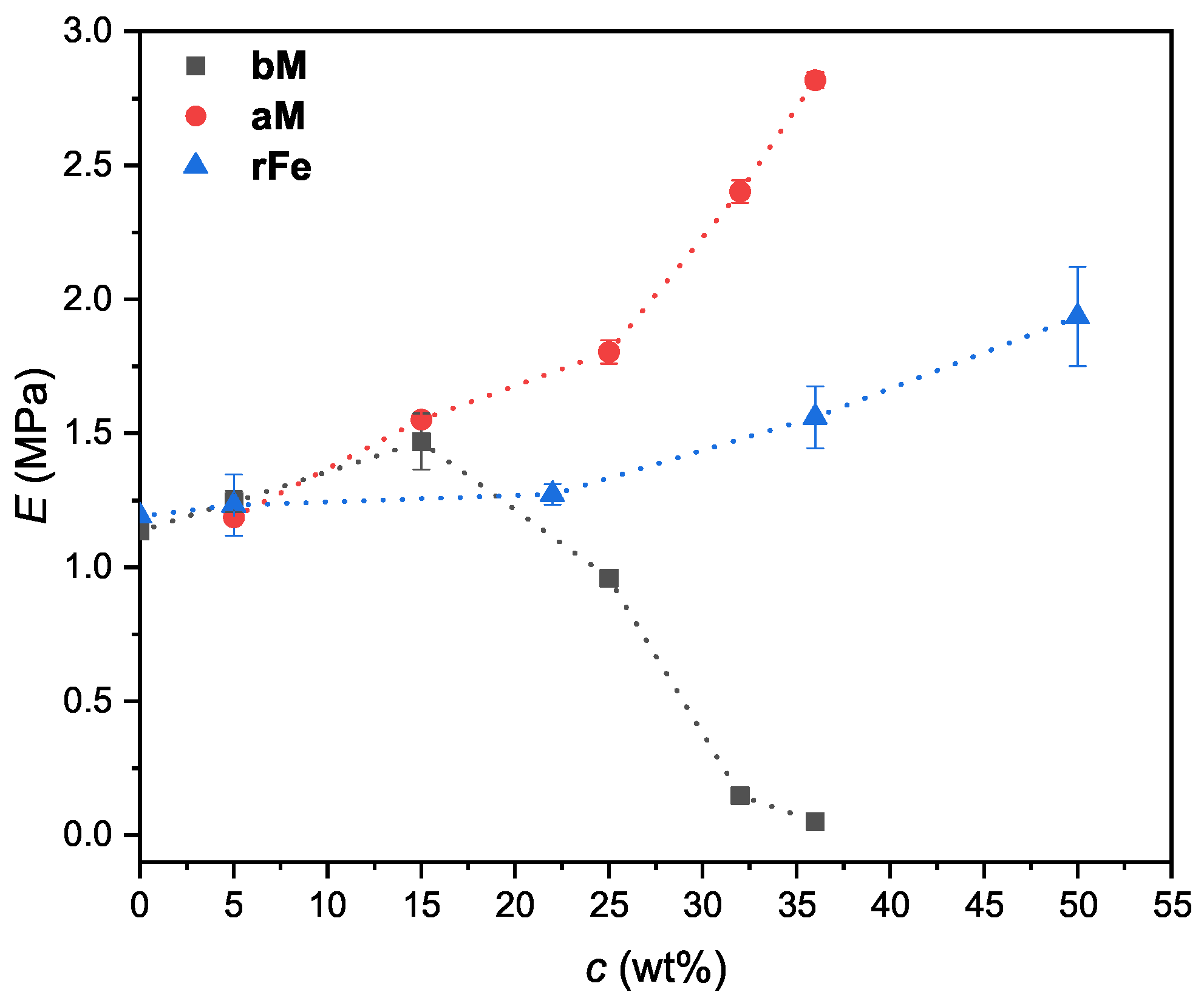
We have determined the elastic modulus of the samples in quasistatic compression mode. The Young’s modulus was calculated from the force-strain curve as outlined in Section 2.1. We note that the used compression method could yield inaccurate results in some cases, especially for low cylindrical bodies, and therefore we will use the measured Young’s modulus values only for a qualitative comparison between the MREs. Figure 4 shows the Young’s modulus of the MREs as a function of the concentration of the filler. The modulus of the elastomers with bM fillers are increasing with increasing the filler material to 15%. Above 15% the Young’s modulus of the bM MRE samples is rapidly decreasing. In contrast, the modulus of the MREs with aM and rFe fillers shows an increasing trend with increasing the filler content. The aM-filled MREs have a larger modulus than the corresponding rFe MREs. The elasticity difference between the aM and rFe MRE samples comes from the different particle sizes and volumetric concentration of the fillers. At the same concentration by weight, the iron-loaded MREs contain fewer particles by volume (see Table 1) due to larger density.
In case of the bM filler the particles exhibit an inhibitor effect causing an incomplete polymerization of the matrix, which manifests in the observed significant decrease of the modulus. A similar inhibitor effect of the filler particles was observed by Borin et al. [23]. The platinum cross-linking catalyst can be blocked by residual materials (e.g., sulfur containing materials, organometallic compounds, etc.) [24]. According to our elemental analysis of the filler materials the bM magnetite contains sulfur and other metallic compounds besides magnetite (Figure 5), which can be responsible for the inhibition of the catalyst. We note that the reduced modulus of the matrix due to the partial polymerization can affect the response time of the MREs too [25], because the displacement and rotation of the particles is less hindered in a matrix with smaller modulus. In case of aM magnetite, the amount of residual materials is significantly smaller than in case of the bM magnetite (below the detection limit of the EDS, see the spectra in Figure 5), so the cross-linking catalyst is not blocked. Therefore, the modulus of the aM MREs is increasing monotonically with the filler concentration, just like in case of the rFe MREs.
3.2. Field-Induced Deformation
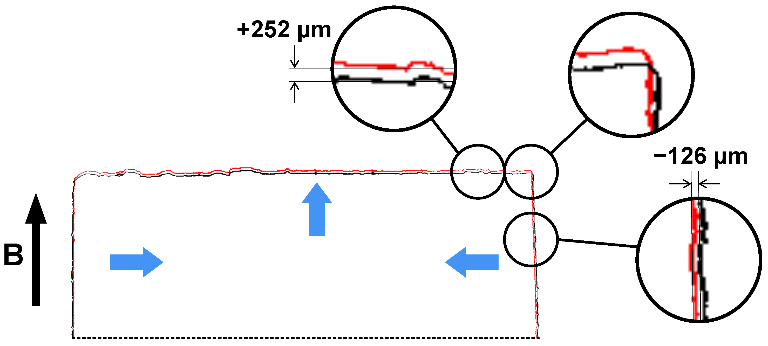
To demonstrate the simultaneous deformation of the whole sample in both axial and radial directions, an example of the contour line before and after the application of the magnetic field (B = 510 mT) is shown in Figure 6 for the bM36 sample, which exhibited the largest deformation. The distance between the two contours was measured at several points (both along the diameter and along the height) and an average dilatation of m was detected in the direction of the field, whereas in the perpendicular direction the average contraction was m. All other samples behaved the same (but with different magnitude): they expanded in the direction of the field, while the diameter shrank. Our results for the deformation of MREs support the observation of other studies, that cylindrical-shaped isotropic samples with 0.47 aspect ratio undergo dilatation in the direction of the applied field. According the simulations of Kalina et al. [15] dilatation is expected until the height-to-width ratio is smaller than three, and rectangular shaped MRE bodies will shrink if . From the measured change in height and diameter of the MRE disc, the change of volume was estimated, which was under 0.1% in all cases. The deformation of the MRE bodies under investigation could be regarded to conserve the overall volume.
Now let us examine the effect of the field strength and particle concentration on the field-induced deformation in the axial direction. The deformation in this case was measured in the high resolution mode of the camera system with the target placed on top of the samples, so the measured data is an average for the whole top surface.
Effect of Magnetic Field
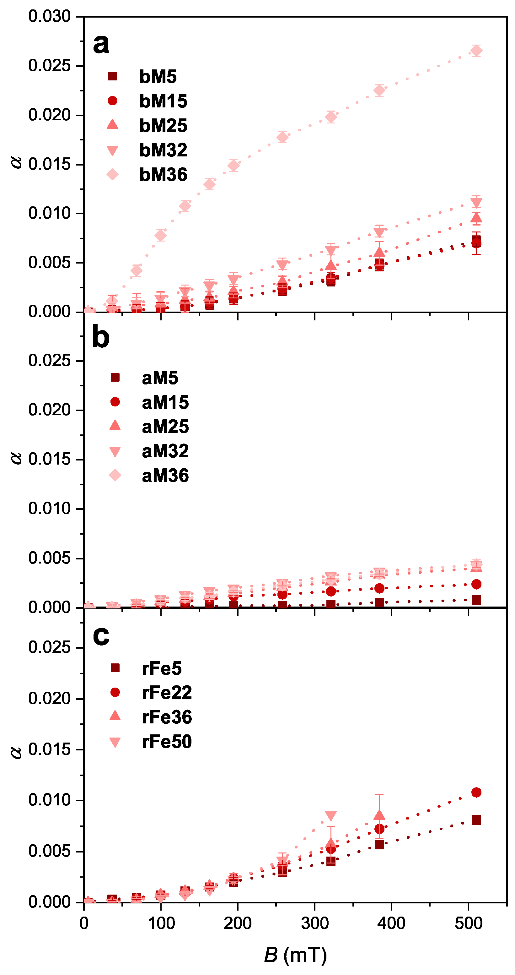
The relative deformation parallel with the axis of the cylindrical samples as a function of the magnetic flux density is shown in Figure 7. As B was increased, the dilatation of the MREs became larger in cases of all three filler materials, but the exact trend depends on the type and concentration of the filler. At lower field strengths, increases according a power law, whereas in the larger field strength region the dilatation of the MREs approaches saturation. The rFe-loaded MREs show slightly different behavior than the other two MREs with magnetite fillers: the power law increase turns into the saturation region only at higher flux density (above 400 mT). At large filler content (36 wt% and 50 wt%) the dilation of the iron-loaded samples could not be measured by this method, because in strong magnetic fields the samples moved from the sample holder. This would be avoidable if the uniformity of the field would be better than the present 1%.
Effect of the Particle Concentration
The magnitude of the deformation depends not only on the field strength, but the filler content, the filler’s magnetic properties (magnitude of the demagnetizing field), and also the elasticity of the matrix influence it. However, the filler particles can modify the elasticity of the matrix through the inhibitor effect outlined in Section 3.1; therefore these two factors are not independent. The concentration of the particles and the elasticity of the matrix work against each other in regard to the magnitude of the deformation. With increasing particle loading, larger dilatation is usually observed. On the other hand, if the elasticity of the matrix is increased, the deformation and the relative MR effect is typically reduced [26,27]. We note that in some cases, there is not such a direct relationship between the elastic modulus of the matrix and the extent of the field-induced deformation [28].
In case of the aM and bM magnetite fillers, the effect of the particles on the deformation is similar due to the similar particle size (see Figure 3) and magnetic properties (susceptibilities of the particles are and , therefore the demagnetizing field have nearly the same magnitude), but the elasticity of the matrix is significantly different. If we compare the concentration dependence of the dilatation in case of these two fillers the behavior is different, as can be seen in Figure 8. The aM-filled MREs display a near linear concentration dependence, whereas the dilatation of the bM MREs at high particle concentration is considerably enlarged. This difference is the result of the reduced modulus of the matrix in case of the bM filler due to the incomplete polymerization. This can be also seen in the concentration dependence of the resulting modulus of the elastomers (Figure 4), which is a fraction in case of the bM filler compared to the aM MREs at 36 wt% (0.051 MPa vs. 2.774 MPa).
However, if different particles were embedded in a matrix with the same modulus, then the dilatation of the samples was changing near linearly with the concentration of the particles, as can be seen when the aM- and rFe-filled MREs are compared (Figure 8b,c). The relative dilatation of the rFe MREs was larger compared to the aM-filled MREs at the same conditions. This could be caused by the larger magnetic susceptibility of the iron particles (5.66 vs. 0.34), which affects the magnitude of the demagnetization field too. The resulting modulus of these MREs increases with the filler content (Figure 4), but there is a difference in the magnitude, which comes from the fact that the number of iron particles is smaller than the number of magnetite particles at the same concentration by weight.
4. Conclusions
Behavior of polydimethylsiloxane-based magnetorheological elastomers with different filler materials were investigated in uniform magnetic field. The filler materials were magnetite and iron powders with different particle size distribution. The MRE samples were disc shaped with a height-to-width ratio of 0.47.
- In all our cases, the sign of the deformation was positive; thus dilatation was observed in the direction of the field, which is consistent with the aspect ratio of the samples. The estimated change in volume of the MRE discs remained under 0.1%; thus, the overall volume was conserved during the field-induced deformation.
- With increasing field strength, the dilatation of the MREs became larger in cases of all three filler materials, but the exact trend depended on the type and concentration of the filler.
- The aM-filled MREs displayed a near linear concentration dependence, while the dilatation of the bM MREs at high particle concentration was considerably enhanced, which was attributed to the incomplete polymerization, and thus to the reduced modulus of the matrix. This inhibitor effect of the bM particles could be caused by the residual materials detected by elemental analysis.
- By comparing the aM- and rFe-filled MREs—in which no inhibitor effect was observed, and thus the elastic matrix had the same modulus—the dilatation of the samples was increasing near linearly with the concentration of the particles.
- The resulting Young’s modulus of the MREs was increasing with the particle loading. The exception was the bM magnetite filler where the abovementioned inhibited cross-linking of the matrix was responsible for the observed softening of the MREs at high particle concentration.
It would be interesting the experimentally verify the effect of the aspect ratio on the sign and magnitude of deformation. Such investigations applying the video microscopic method used here are currently in preparation.
Author Contributions
Conceptualization, D.B., S.G. and B.H.; methodology, D.B., S.G. and B.H.; software, S.G.; validation, D.B., S.G., B.H. and I.S.; formal analysis, D.B., S.G. and B.H.; investigation, D.B. and S.G.; writing—original draft preparation, D.B. and S.G.; writing—review and editing, B.H. and I.S.; visualization, B.H. and S.G.; supervision, I.S.; funding acquisition, I.S. All authors have read and agreed to the published version of the manuscript.
Funding
This work was supported by the TKP2020-NKA-10 project financed under the 2020-4.1.1-TKP2020 Thematic Excellence Programme by the National Research, Development and Innovation Fund of Hungary.
Institutional Review Board Statement
Not applicable.
Informed Consent Statement
Not applicable.
Data Availability Statement
All data generated and analyzed during this study are available from the corresponding author on reasonable request.
Conflicts of Interest
The authors declare no conflict of interest. The funders had no role in the design of the study; in the collection, analyses, or interpretation of data; in the writing of the manuscript; or in the decision to publish the results.
References
- Sorokin, V.V.; Stepanov, G.V.; Shamonin, M.; Monkman, G.J.; Khokhlov, A.R.; Kramarenko, E.Y. Hysteresis of the Viscoelastic Properties and the Normal Force in Magnetically and Mechanically Soft Magnetoactive Elastomers: Effects of Filler Composition, Strain Amplitude and Magnetic Field. Polymer 2015, 76, 191–202. [Google Scholar] [CrossRef]
- Winger, J.; Schümann, M.; Kupka, A.; Odenbach, S. Influence of the Particle Size on the Magnetorheological Effect of Magnetorheological Elastomers. J. Magn. Magn. Mater. 2019, 481, 176–182. [Google Scholar] [CrossRef]
- Böse, H.; Röder, R. Magnetorheological Elastomers with High Variability of Their Mechanical Properties. J. Phys. Conf. Ser. 2009, 149, 012090. [Google Scholar] [CrossRef]
- Stepanov, G.V.; Borin, D.; Odenbach, S. Magnetorheological Effect of Magneto-Active Elastomers Containing Large Particles. J. Phys. Conf. Ser. 2009, 149, 012098. [Google Scholar] [CrossRef]
- Gong, X.L.; Zhang, X.Z.; Zhang, P.Q. Fabrication and Characterization of Isotropic Magnetorheological Elastomers. Polym. Test. 2005, 24, 669–676. [Google Scholar] [CrossRef]
- Ginder, J.M.; Clark, S.M.; Schlotter, W.F.; Nichols, M.E. Magnetostrictive phenomena in magnetorheological elastomers. Int. J. Mod. Phys. B 2002, 16, 2412–2418. [Google Scholar] [CrossRef]
- Wu, S.; Hu, W.; Ze, Q.; Sitti, M.; Zhao, R. Multifunctional Magnetic Soft Composites: A Review. Multifunct. Mater. 2020, 3, 042003. [Google Scholar] [CrossRef]
- Kankanala, S.V.; Triantafyllidis, N. On Finitely Strained Magnetorheological Elastomers. J. Mech. Phys. Solids 2004, 52, 2869–2908. [Google Scholar] [CrossRef]
- Martin, J.E.; Anderson, R.A.; Read, D.; Gulley, G. Magnetostriction of Field-Structured Magnetoelastomers. Phys. Rev. E 2006, 74, 051507. [Google Scholar] [CrossRef] [Green Version]
- Ivaneyko, D.; Toshchevikov, V.; Saphiannikova, M.; Heinrich, G. Effects of Particle Distribution on Mechanical Properties of Magneto-Sensitive Elastomers in a Homogeneous Magnetic Field. Condens. Matter Phys. 2012, 15, 33601. [Google Scholar] [CrossRef]
- Diguet, G.; Beaugnon, E.; Cavaillé, J.Y. From Dipolar Interactions of a Random Distribution of Ferromagnetic Particles to Magnetostriction. J. Magn. Magn. Mater. 2009, 321, 396–401. [Google Scholar] [CrossRef]
- Coquelle, E.; Bossis, G. Magnetostriction and Piezoresistivity in Elastomers Filled with Magnetic Particles. J. Adv. Sci. 2005, 17, 132–138. [Google Scholar] [CrossRef] [Green Version]
- Morozov, K.; Shliomis, M.; Yamaguchi, H. Magnetic Deformation of Ferrogel Bodies: Procrustes Effect. Phys. Rev. E 2009, 79, 040801. [Google Scholar] [CrossRef] [PubMed]
- Zhou, G.Y.; Jiang, Z.Y. Deformation in Magnetorheological Elastomer and Elastomer–Ferromagnet Composite Driven by a Magnetic Field. Smart Mater. Struct. 2004, 13, 309–316. [Google Scholar] [CrossRef]
- Kalina, K.A.; Metsch, P.; Brummund, J.; Kästner, M. A Macroscopic Model for Magnetorheological Elastomers Based on Microscopic Simulations. Int. J. Solids Struct. 2020, 193–194, 200–212. [Google Scholar] [CrossRef]
- Dobroserdova, A.; Schümann, M.; Borin, D.; Novak, E.; Odenbach, S.; Kantorovich, S. Magneto-Elastic Coupling as a Key to Microstructural Response of Magnetic Elastomers with Flake-like Particles. Soft Matter 2022, 18, 496–506. [Google Scholar] [CrossRef] [PubMed]
- Guan, X.; Dong, X.; Ou, J. Magnetostrictive Effect of Magnetorheological Elastomer. J. Magn. Magn. Mater. 2008, 320, 158–163. [Google Scholar] [CrossRef]
- Silva, J.A.; Gouveia, C.; Dinis, G.; Pinto, A.M.; Pereira, A.M. Giant Magnetostriction in Low-Concentration Magnetorheological Elastomers. Compos. B. Eng. 2022, 243, 110125. [Google Scholar] [CrossRef]
- Böse, H.; Gerlach, T.; Ehrlich, J. Magnetorheological Elastomers—An Underestimated Class of Soft Actuator Materials. J. Intell. Mater. Syst. Struct. 2021, 32, 1550–1564. [Google Scholar] [CrossRef]
- Gong, X.; Liao, G.; Xuan, S. Full-Field Deformation of Magnetorheological Elastomer under Uniform Magnetic Field. Appl. Phys. Lett. 2012, 100, 211909. [Google Scholar] [CrossRef]
- Borbáth, T.; Günther, S.; Borin, D.; Gundermann, T.; Odenbach, S. XμCT Analysis of Magnetic Field-Induced Phase Transitions in Magnetorheological Elastomers. Smart Mater. Struct. 2012, 21, 105018. [Google Scholar] [CrossRef]
- Gundermann, T.; Günther, S.; Borin, D.; Odenbach, S. Detection of the Surface Deformation of Magneto-Active Composites Using X-Ray μ-Tomography. Magnetohydrodynamics 2013, 49, 494–498. [Google Scholar] [CrossRef]
- Borin, D.; Günther, D.; Hintze, C.; Heinrich, G.; Odenbach, S. The Level of Cross-Linking and the Structure of Anisotropic Magnetorheological Elastomers. J. Magn. Magn. Mater. 2012, 324, 3452–3454. [Google Scholar] [CrossRef]
- Lukin, R.Y.; Kuchkaev, A.M.; Sukhov, A.V.; Bekmukhamedov, G.E.; Yakhvarov, D.G. Platinum-Catalyzed Hydrosilylation in Polymer Chemistry. Polymers 2020, 12, 2174. [Google Scholar] [CrossRef] [PubMed]
- Horváth, B.; Decsi, P.; Szalai, I. Measurement of the Response Time of Magnetorheological Fluids and Ferrofluids Based on the Magnetic Susceptibility Response. J. Intell. Mater. Syst. Struct. 2022, 33, 918–927. [Google Scholar] [CrossRef]
- Wu, J.; Gong, X.; Fan, Y.; Xia, H. Improving the Magnetorheological Properties of Polyurethane Magnetorheological Elastomer through Plasticization. J. Appl. Polym. Sci. 2012, 123, 2476–2484. [Google Scholar] [CrossRef]
- Khairi, M.H.A.; Noor, E.E.M.; Ubaidillah, U.; Aziz, S.A.A.; Mazlan, S.A.; Tarmizi, S.M.A.; Nordin, N.A. Enhancement of Magneto-Induced Modulus by the Combination of Filler and Plasticizer Additives-Based Magnetorheological Elastomer. Materials 2022, 15, 6396. [Google Scholar] [CrossRef]
- Böse, H. Viscoelastic properties of silicone-based magnetorheological elastomers. Int. J. Mod. Phys. B 2007, 21, 4790–4797. [Google Scholar] [CrossRef]
Figure 1.
Schematics of the measurement system (a). The distribution of the magnetic flux density between the poles in the volume of the sample (dimensions indicated are in scale) is uniform within 1% (b). The edge of the target (shown by the red line) placed on top of the sample serves as a reference line for the detection of the deformation (c).

Figure 2.
The samples with different fillers: reduced iron powder (rFe), Sigma-Aldrich magnetite (aM), and Bayferrox 318M magnetite (bM). The size of the MREs was the same in all cases as indicated.
Figure 2.
The samples with different fillers: reduced iron powder (rFe), Sigma-Aldrich magnetite (aM), and Bayferrox 318M magnetite (bM). The size of the MREs was the same in all cases as indicated.

Figure 3.
Particle size distribution of the bM magnetite (a), aM magnetite (b), and the rFe iron (c) filler materials measured with laser diffraction method. Columns represent the distribution density (Q3(x) in %) and the solid lines represent the cumulative distribution (dQ3(x) in %). The inset pictures show the morphology of the fillers according the SEM images.

Figure 4.
The zero-field Young’s modulus of the MREs with different particle loadings. The dotted line is a guide for the eye. In most cases, the error bar is smaller than the symbol.
Figure 4.
The zero-field Young’s modulus of the MREs with different particle loadings. The dotted line is a guide for the eye. In most cases, the error bar is smaller than the symbol.

Figure 5.
Chemical elemental analysis of bM and aM magnetite fillers. On the EDS spectrum of bM magnetite other elements are detected besides the oxygen and iron. The carbon peak present in both spectra comes from the material of the SEM sample holders.
Figure 5.
Chemical elemental analysis of bM and aM magnetite fillers. On the EDS spectrum of bM magnetite other elements are detected besides the oxygen and iron. The carbon peak present in both spectra comes from the material of the SEM sample holders.

Figure 6.
Contour of the sample bM36. Black is the contour at B = 0 mT, and red is the contour at B = 510 mT. The thick arrows indicate the directions of the field-induced deformation.
Figure 6.
Contour of the sample bM36. Black is the contour at B = 0 mT, and red is the contour at B = 510 mT. The thick arrows indicate the directions of the field-induced deformation.

Figure 7.
Deformation of samples as a function of the magnetic flux density at different concentrations of bM magnetite (a), aM magnetite (b), and rFe iron (c) filler. The dotted lines are a guide for the eye. In some cases, the error bar is smaller than the symbol.
Figure 7.
Deformation of samples as a function of the magnetic flux density at different concentrations of bM magnetite (a), aM magnetite (b), and rFe iron (c) filler. The dotted lines are a guide for the eye. In some cases, the error bar is smaller than the symbol.

Figure 8.
The dependence of the dilation on the particle loading in case of different filler materials (bM magnetite (a), aM magnetite (b), and rFe iron (c)) at various magnetic flux densities. The dotted lines are a guide for the eye. In some cases, the error bar is smaller than the symbol.
Figure 8.
The dependence of the dilation on the particle loading in case of different filler materials (bM magnetite (a), aM magnetite (b), and rFe iron (c)) at various magnetic flux densities. The dotted lines are a guide for the eye. In some cases, the error bar is smaller than the symbol.


Table 1.
The type and concentration of the filler materials in the fabricated samples.
| Sample | Filler Type | Filler Concentration | |
|---|---|---|---|
| (wt%) | (vol%) | ||
| bM5 | 5.0 | 1.0 | |
| bM15 | 15.0 | 3.2 | |
| bM25 | 25.0 | 5.9 | |
| bM32 | 32.0 | 8.1 | |
| bM36 | 36.0 | 9.5 | |
| aM5 | 5.0 | 1.0 | |
| aM15 | 15.0 | 3.2 | |
| aM25 | 25.0 | 5.9 | |
| aM32 | 32.0 | 8.1 | |
| aM36 | 36.0 | 9.5 | |
| rFe5 | 5.1 | 0.7 | |
| rFe22 | 21.6 | 3.3 | |
| rFe36 | 36.4 | 6.6 | |
| rFe50 | 50.0 | 11.0 | |
Publisher’s Note: MDPI stays neutral with regard to jurisdictional claims in published maps and institutional affiliations. |
© 2022 by the authors. Licensee MDPI, Basel, Switzerland. This article is an open access article distributed under the terms and conditions of the Creative Commons Attribution (CC BY) license (https://creativecommons.org/licenses/by/4.0/).
Share and Cite
MDPI and ACS Style
Balogh, D.; Guba, S.; Horváth, B.; Szalai, I. Magnetic Field-Induced Deformation of Isotropic Magnetorheological Elastomers. Magnetochemistry 2022, 8, 146. https://0-doi-org.brum.beds.ac.uk/10.3390/magnetochemistry8110146
AMA Style
Balogh D, Guba S, Horváth B, Szalai I. Magnetic Field-Induced Deformation of Isotropic Magnetorheological Elastomers. Magnetochemistry. 2022; 8(11):146. https://0-doi-org.brum.beds.ac.uk/10.3390/magnetochemistry8110146
Chicago/Turabian StyleBalogh, Diána, Sándor Guba, Barnabás Horváth, and István Szalai. 2022. "Magnetic Field-Induced Deformation of Isotropic Magnetorheological Elastomers" Magnetochemistry 8, no. 11: 146. https://0-doi-org.brum.beds.ac.uk/10.3390/magnetochemistry8110146
Note that from the first issue of 2016, this journal uses article numbers instead of page numbers. See further details here.