Article

Positron Annihilation Spectroscopy as a Diagnostic Tool for the Study of LiCoO2 Cathode of Lithium-Ion Batteries

1
Section of Chemistry for the Technology (ChemTech), Department of Industrial Engineering, University of Padova, Via Marzolo 9, I-35131 Padova, Italy
2
LNESS and Department of Physics, Politecnico di Milano, Via Anzani 42, I-22100 Como, Italy
3
INFN Milano, Via Celoria 16, I-20133 Milano, Italy
4
Physics Department, School of Engineering Science, LUT-University, FI-53851 Lappeenranta, Finland
5
Department of Physics, Northeastern University, Boston, MA 02115, USA
*
Authors to whom correspondence should be addressed.
These authors contributed equally.
Submission received: 7 July 2021 / Revised: 24 July 2021 / Accepted: 26 July 2021 / Published: 29 July 2021

Abstract

:
Positron annihilation spectroscopy using lifetime and Doppler broadening allows the characterization of the lithiation state in LiCoO2 thin film used in cathode of lithium-ion batteries. The lifetime results reflect positron spillover because of the presence of graphite in between the oxide grains in real cathode Li-ion batteries. This spillover produces an effect in the measured positron parameters which are sensitive to delocalized electrons from lithium atoms as in Compton scattering results. The first component of the positron lifetime corresponds to a bulk-like state and can be used to characterize the state of charge of the cathode while the second component represents a surface state at the grain-graphite interface.

1. Introduction

Li-ion batteries are dominating the market of energy storage devices in the portable electronic and electric vehicle fields [1]. The development of novel and high-performing materials in this technology is an urgent need. In this regard, the research is primarily focused on: (i) the transition from the costly and capacity limited graphite anode towards silicon and lithium metal [2,3,4,5,6], (ii) the designing of solid-state ceramic and polymer electrolytes endowed with a wide electrochemical stability window and stable towards the Li-metal anode [7,8,9,10,11,12,13,14,15,16], and (iii) the development of high-voltage and high-energy cathode materials [17,18,19,20,21,22,23]. This latter component (i.e., the cathode) typically limits the energy density of the resulting full cell, thus becoming one of the most important materials to focus attention on. Therefore, a fundamental understanding of the processes occurring during the operation of the battery, with particular attention at the changes resulting from the Li+ insertion and extraction reactions is required in order to assist the designing of the materials. Moreover, the development of battery management systems (BMSs) is becoming one of the most prolific topics in the applied research in the battery field [24,25,26,27]. Thus, the identification of suitable signals to be monitored during the battery cycling is needed in order to analyze and predict the state of health (SOH) and state of charge (SOC) of the device.
The introduction of a one-step non-invasive technique that allows probing of cathode materials acts as a true game changer for this field of applied research. Positron annihilation spectroscopy (PAS) is an established technique in materials science with widespread uses in metals and metal alloys [28], porous materials [29], semiconductors [30,31,32], solar cells [33], etc. In the PAS technique, positrons e+, positively charged antiparticles of electrons, are implanted into the studied material and annihilate either as free positrons with the electrons in two 511 keV gamma-rays or in the form of a positron-electron bonded state called positronium. PAS has been recently applied in the battery field in order to investigate the structure and properties of the materials at an atomistic scale [34]. PAS is able to detect the formation of vacancies and defects in the cathode lattice during the Li+ insertion and extraction electrochemical processes [35,36]. This ability is the result of the defect-specific variation of the e+–e− annihilation properties which arise when e+ are trapped at the free-volume type defects [37,38]. Vacancies can be both positively or negatively charged, as they occur when oxygen or cation vacancies are present, respectively [39].
In this paper, positron annihilation spectroscopy (PAS) has been used as a diagnostic technique to investigate the influence at the mesoscale of morphology on the electrochemical behavior of a conventional cathode material.

2. Results and Discussion

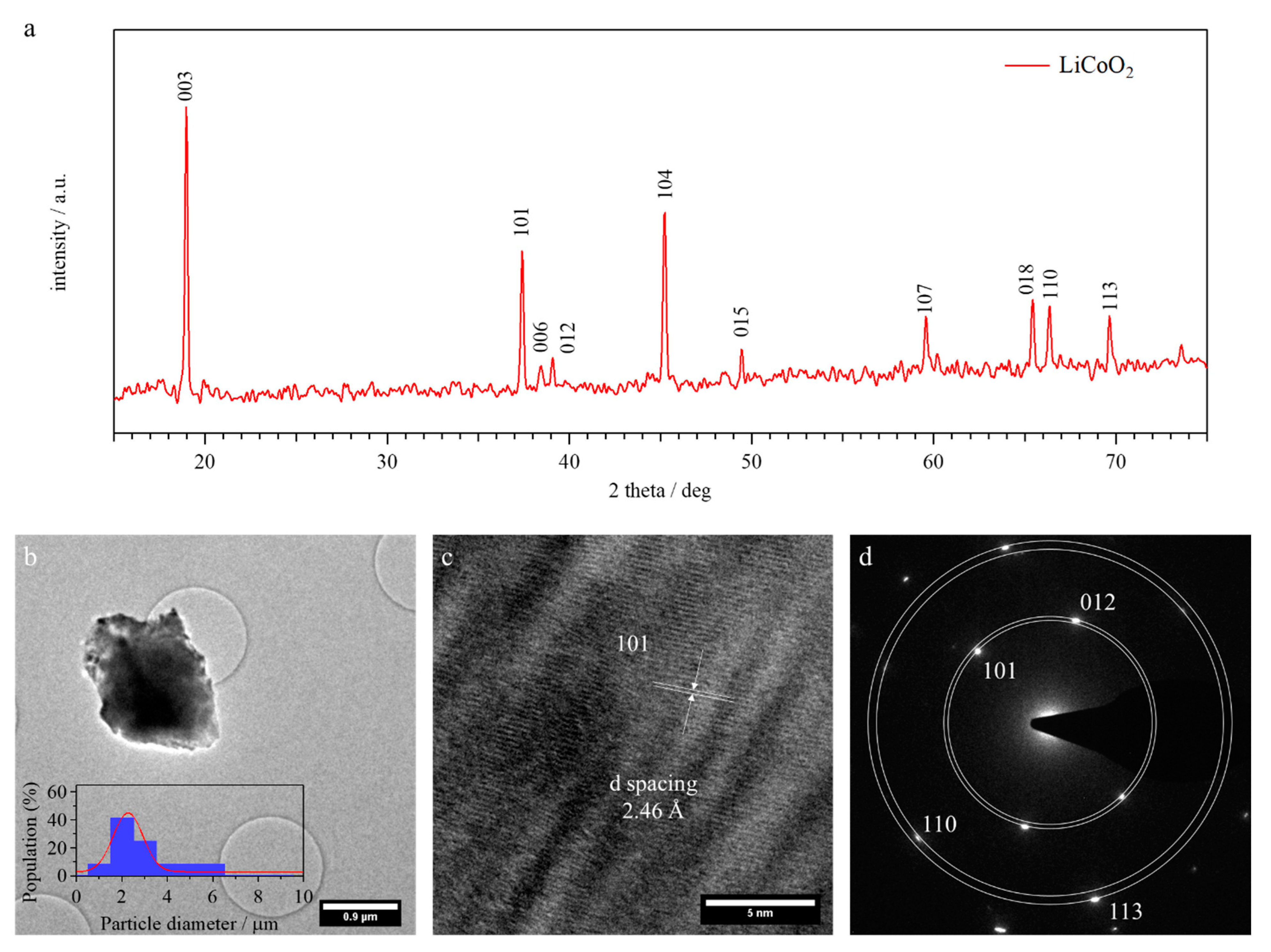
2.1. Structure and Morphology

The structure of pristine LCO is studied by means of powder wide-angle X-ray diffractometry (WAXD); the results are shown in Figure 1a. The investigated material reveals a trigonal crystal system with an R -3 m space group, which is the typical structure of LiCoO2 observed in the literature [40]. In particular, Co atoms are present into CoO6 octahedra, and lithium ions are hosted into octahedral cavities formed by a suitable displacement of oxygen atoms. In this way, the layered structure of LCO is suitable for the intercalation and de-intercalation of lithium ions during the operation of the battery system. During charge, when Li+ ions are extracted from the cathode, Co3+ metal centers are oxidized to Co4+, thus modifying the whole electronic structure of the investigated material. During the discharge process, Li+ ions intercalate into the crystal system and cobalt ions are reduced backwards to their Co3+ oxidation state, repristinating the initial electronic arrangement.
Further details on the high crystallinity of LCO are given by high-resolution transmission electron microscopy (HR-TEM) images (Figure 1b,c) and the selected area diffraction (SAD) pattern (Figure 1d). The LCO material investigated in this work consists of single-crystal particles of ca. 2 μm diameter. Well-defined lattice fringes are observed in HR-TEM images (Figure 1c), thus revealing a high crystallinity. In particular, a d-spacing of ca. 2.46 Å is determined, which is consistent with the 100 (hkl) reflection also detected in WAXD studies. The SAD pattern (Figure 1d) is coincident with that expected for a LiCoO2 cathode material, since the d-spacings resulting from this investigation are coincident with the 101, 012, 110, and 113 (hkl) reflections observed in the WAXD diffractogram.

2.2. Positron Annihilation Lifetime Spectroscopy

2.2.1. Reference Samples

For a better understanding of the thin cathodes results of positron annihilation lifetime spectroscopy (PALS), two reference materials were measured. One of them is the aluminum foil used as the substrate of the cathodes and the other is the graphite powder used in the mixture of cathode grains. To perform the measurement, the aluminum foil was folded on itself many times and then it was slightly pressed to prevent air remaining between the Al foils. Thus, a 1.5 mm thick sample with a surface of about 1 cm2 was obtained. The PALS measurement of the Al foils was compared to that of a high purity polycrystalline Al sample (99.999%) annealed. A long lifetime component (228–235 ps, in Table 1) appears in both samples, associated to vacancies or vacancy-like defects [41]. The rolled material, which is used as a current collector, contains a high dislocation density due to the important plastic deformation during production, and the intensity of this long lifetime component is about 85%. Positrons trapped at dislocations tend to diffuse inside them, and then to be localized and annihilated in an open volume like a vacancy (as a dislocation crossing). Instead, the polycrystalline Al annealed sample has a low intensity of this long lifetime component (~4%), which is an indication that it contains a low density of thermal vacancies and dislocation. Table 1 shows that the rolled material has an average lifetime of 208 ps, near 30% higher than the undeformed Al (162 ps). Both Al samples well follow the trapping model with a bulk component of about 161 ps, according to the literature [41].
The graphite powder was sintered in two tablets (4 mm thick and 1.5 cm2 area) to perform the PALS measurement. This sample possesses two lifetime components: (i) the long lifetime component (~400 ps), the dominant one (87%), is associated to ”free volume” where ortho-positronium is formed which annihilates by pick-off in two gamma-rays; and (ii) the shorter component in part is due to the graphite microstructure and para-positronium contribution. The average lifetime of the graphite sample is 362 ps.

2.2.2. Cathode Samples

The PALS measurements were performed in real LiXCoO2 cathodes used in batteries and produced with a thickness devoted to improving the battery performance. The measurement represents a challenge from the PALS point of view, as the dimensions are not optimized to avoid annihilation in extra-cathodic zones. This cathode material was studied previously by means of PALS [37] using more idealized materials. Figure 2a shows the schematic setup used for the PALS measurements. These were performed using a sandwich setup, in which two pairs of identical cathode samples were placed with the 22Na source of positrons in between. Two external annealed Al samples (1.5 mm thick) close the sandwich. The mean mass density of the LiCoO2 cathode samples were obtained from gas pycnometer measurements (4.52 ± 0.01 g/cm3). Table 2 shows that the thickness of the cathode electrodes is about 60 µm and the Al foil substrate 15 µm (d1 and d2 in Figure 2a). After the subtraction of the Kapton and spurious components from the spectra (see Materials and Methods section), following the formulation of Brandt [42] with an approximative version of a multilayer formulation used for the β+ emission 22Na profile, it was possible to estimate the fraction of positrons implanted into the LiXCoO2 grains embedded with a low percentage of graphite and polyvinyl difluoride (PVDF) (see Materials and Methods section). This fraction, after the subtraction of the Kapton contribution, results about 91 (3)%; the other positron fraction is implanted inside the Al supporting foil and into the external Al polycrystalline sample. Considering the thicknesses of the materials and the typical diffusion length inside the crystal oxide (~60 nm, see Table 3 in Section 2.3) and in the Al support (~100 nm), we can assume that the implantation fraction practically corresponds to the annihilation fraction.
The PALS spectra measured in the composite oxide LiXCoO2 samples have a complex unresolved distribution that can be analyzed with two lifetime components; the longer of about 315–327 ps (Table 2) is mainly associated to the contribution of the Al foil (τav ~208 ps, Table 1) and the graphite contribution near the grain boundary of the crystal oxides (τav ~362 ps, Table 1). It is important to note that the LiXCoO2 grain average dimension is about 2 µm (Figure 1b). Appendix A shows the Langevin function and Figure A1 shows an estimation of the probability (1 − η) to reach the grain boundary as a function of the rate between the grain diameter and the positron diffusion length. Following this estimation, we consider that only a low percentage of near 3% of the positrons implanted into the grains can reach the grain boundary. On the other hand, the weight fraction of the mixture graphite/PVDF is about 6.25 wt.%; therefore, positrons implanted in the extra-grain zone annihilate in this zone and mainly form part of the long lifetime component. Another factor to be considered is linked to the charge process of the battery cathode. During this process, the electrolyte takes contact with the grain boundary of the LiXCoO2 crystal and the graphite/PVDF mixture. Therefore, a fraction of electrolyte after charging remains near the Li0.5CoO2 grain boundary. This process affects the extra grain substance producing a macroscopic effect that increase the cathode thickness in about 14% and presumably mainly also affects the long lifetime component.
It is interesting to note in Table 2 that the intensity of the long lifetime component I2 is significant. The value of this intensity is close to 30%, while the prediction based on the diffusion model describing the fraction of positrons reaching the LixCoO2 grain boundary is lower, as proposed by the Langevin formula (Appendix A). An important factor to consider understanding the microstructure of cathodes “in operando” is a possible effect near the grain boundary and inside the grain due to the influence of graphite present outside this domain. Presumably, this effect could change the potential energy of the grain and can affect the properties of the cathode oxide, including the positron lifetime.
The first lifetime component instead is mainly associated to the cathode crystal oxide. However, a minority contribution of the Al foils, the short graphite component, and the external Al sample is not excluded as previously indicated. Table 2 shows that the first lifetime component of the LiCoO2 cathode sample is 163 ps. Instead, the lifetime of the Li0.5CoO2 cathode is 181 ps. The intensity of this component is about 70%, a little higher in the case of low Li contents (i.e., Li0.5CoO2). Theoretical calculations using the generalized gradient approximation (GGA) [34] give an estimation of the expected positron lifetime values in these cathodes measured in ideal conditions. The GGA lifetime values in LiCoO2 is 131 ps, and in the case of Li0.5CoO2 there are two possible lifetimes: (i) for isolated Li vacancies, the value is 179 ps; and (ii) for Li vacancy clusters, the value is increased to 214 ps. The comparison between the measured and calculated values indicates a correspondence, within the experimental error, in the case of Li0.5CoO2 for isolated vacancies. A contribution of the vacancy clusters inside to the long unresolved lifetime component is not excluded. Instead, the measured value turns out to be much higher than the calculated one in the case of the discharged battery for the LiCoO2 structure. It is important to note that thermal Li vacancies and, in general, a minor vacancy concentration or other defects present in the grain microstructure could influence the measured value of the first lifetime component (τ1). This effect introduces uncertainty when determining the exact vacancy concentration, or percentage of charge in the battery, if this were the objective of the measurements. Presumably, other short components discussed before can affect the measured value of τ1 (as the Al contribution). In any case, the measured values follow the trend indicated by the theoretical calculations, which leads us to think that the description is going in the right direction.
The criteria of the PALS analysis previously studied by Parz et al. [37] is different. These authors used a different criterion for the Al contribution subtraction. However, the results of the cathode oxide follow the same tendency of the average positron lifetime result found in the present work (Table 2).

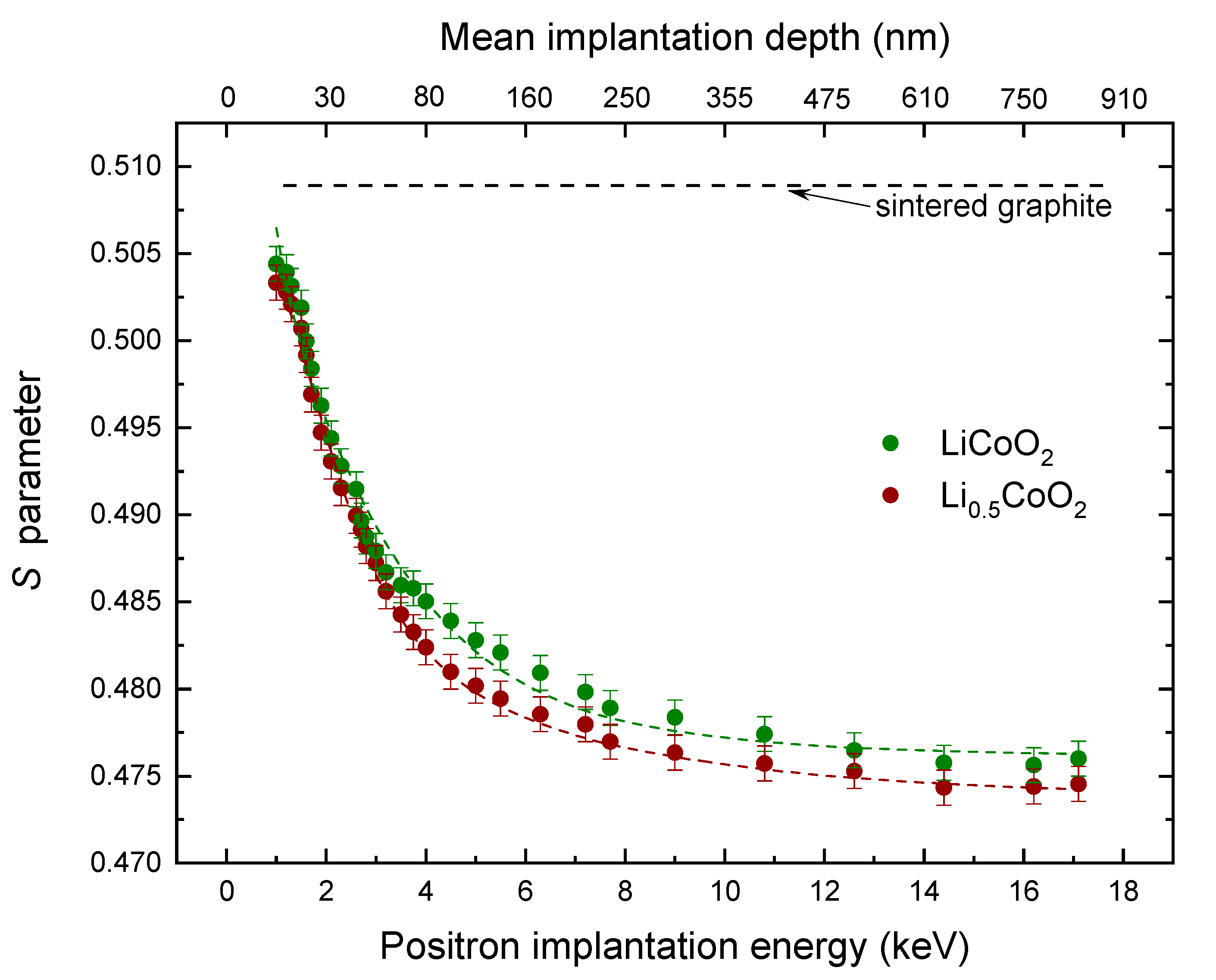
2.3. Doppler Broadening

Figure 3 shows the evolution of the S parameter measured for the LiXCoO2 cathode samples as a function of the positron implantation energy. These measurements were performed by means of a positron beam. Figure 2b shows the set-up scheme. Positrons are implanted at different energies with a characteristic implantation profile that depends on the mass density of the studied material. The implantation depth of the positrons was lower than 1 μm for the higher energy used. The S parameter is mainly correlated with the annihilation of the valence electrons of the material, and its values are associated with the chemical environment surrounding annihilation sites. The reference sintered graphite measurement results almost constant and the average value (SGraphite = 0.509 (1)) is indicated with a dashed black line. For implantation energies higher than 3 keV, the S parameter of the discharged cathodic material (LiCoO2, green symbols) tends to be higher than the partially charged material (Li0.5CoO2, brown symbols), although the differences are not significant within the experimental error. A higher value of the central part of the peak as a function of the Li contains was observed by Barbiellini et al. [43] using X-ray Compton scattering measurements. These correspond to an increase of S parameter in the present work. Instead, Parz et al. [37] observe that the behavior of the S parameter tends to be opposite with the Li concentration. In fact, this is an argument to be studied in more detail because, in general, the S parameter follows the lifetime tendency. Presumably, the other extra-cathode materials measured in this work and the influence of the chemistry outside the oxide grain (mainly graphite) can affect the positronic parameters. This effect could be rationalized by a strong distortion of the positron wave-function induced by graphite reported by Cartier et al. [44]. In fact, if the positron wave-function spills over the grains it becomes less sensitive to the Li ion vacancies. Therefore, in this case, X-ray Compton and the Doppler broadening experiments can give similar results.
Figure 3 shows a best-fit procedure for the experimental data (green and brown dashed lines) called VEPFIT [45] based on the solution of the diffusion equation for positrons in layers, considering the energy-dependent positron implantation profiles (Makhov profiles). To fit the experimental data, a one-layer model was used, comprising the sample surface and the bulk. It was possible to estimate a set of parameters as the positron diffusion length and S parameter of the surface and bulk knowing the film mass density (Table 3). The positron diffusion length L+ is about 60 nm, and it tends to be shorter in the case of Li0.5CoO2, but it does not differ much within experimental error.

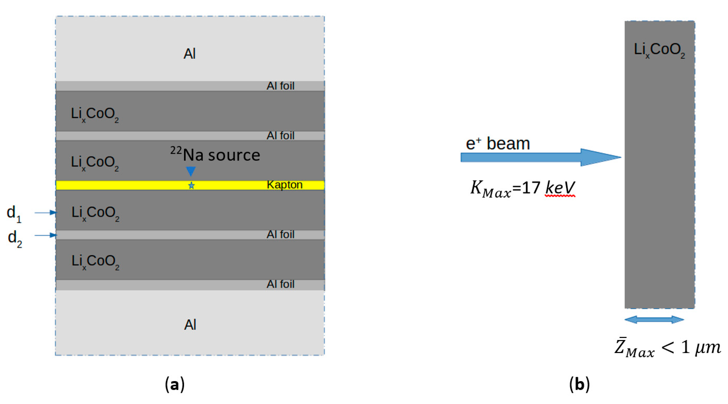
3. Materials and Methods

Lithium cobalt oxide (LCO) was purchased from Nippon Chemical Industrial. Conductive carbon (Super P) was obtained from Alfa Aesar. Lithium metal, lithium hexafluorophosphate in ethylene carbonate—dimethyl carbonate, polyvinyl difluoride (PVDF) and 1-methyl-2-pyrrolidone (NMP, 99.5%, anhydrous) are Sigma-Aldrich products. The battery-grade aluminum foil was purchased from MTI. All materials are used as received.
LCO, conductive carbon, and PVDF densities are determined by means of a Ultrapyc 1200e gas pycnometer from Quantachrome. Results indicates values of 4.9317 ± 0.0003, 2.2375 ± 0.0016, and 1.6870 ± 0.0006 g cm−3, respectively. WAXD diffractogram of LCO is determined using a GNR analytical instrument (mod. eXplorer) with a Cu Kα source in the 2θ range from 15 to 75° with a 0.04° step. LCO microstructure is investigated by means of a high-resolution transmission electron microscope TEM/STEM FEI TECNAI F20 at 200 keV mounting a high-angle collecting annular detector and images were captured with a Gatan MSC794 camera. The samples were suspended in anhydrous cyclohexane by ultrasonication and a droplet of the suspension (ca. 30 μL) was transferred onto a copper grid coated with a carbon Quantifoil R2/1 film.
The cathode mixture is prepared by grinding the active material (LCO) and conductive carbon in a planetary ball-miller for 2 h at 500 rpm. A proper amount of 10 wt.% of PVDF in NMP is then added into the mixture. The final weight ratio of LCO:C:PVDF in the cathodic ink is equal to 93.75:4.00:2.25. The ink is deposited onto an Al foil using a doctor-blade automatic system. The deposit is then dried overnight at 70 °C and at 120 °C in vacuum for 24 h. The cathode electrode thus obtained is cut into disks of 18 mm of diameter.
An EL-CELL type device is assembled into an Ar-filled glovebox using the prepared LCO electrode as cathode, a lithium metal anode, a Celgard separator and a lithium hexafluorophosphate in ethylene carbonate-dimethyl carbonate electrolyte. The cell is charged at a C/5 rate (C = 140 mAh g−1) with a cut-off voltage set at 4.3 V using a Maccor tester station. After the charging process, the battery is disassembled into an Ar-filled glovebox and the cathode electrode is thoroughly washed with anhydrous dimethyl carbonate to remove the excess electrolytes.
The positron annihilation lifetime experiments were performed using a fast–fast coincidence lifetime setup (see [46]) with a time resolution of ~235 ps (FWHM). Time calibration used for a multi-channel analyzer (MCA) card was 25.35 ps per channel. The positron source 22Na (2–3 μCi), deposited between two 7.5 μm thick Kapton foils, was sandwiched between two samples (see Figure 2a the scheme of the cathode oxides measurements). All lifetime measurements were performed at room temperature (21 ± 1 °C) at atmospheric pressure. Positron lifetime spectra of ~4–6 × 10⁶ annihilation events each were recorded. Each positron spectrum required 36–48 h of acquisition time. The intensity of the source component was about 12% for Al samples and 14% for the oxide (LiXCoO2) samples with a value of 382 ps and it was considered throughout the positron data analysis. PALS spectra were fitted using the LT software version 10 [47]. In general, after the Kapton subtraction, three discrete lifetime components τ1 < τ2 < τ3 appear together with their respective intensities, I1, I2 and I3. The goodness parameter value of the fit (χ2/dof) lay between 0.99 and 1.15. The third component τ3, normally called “spurious”, has, in general, a very low intensity I3 (<0.05%) when a metal with a smooth surface is measured, if the source is done well as in this case. The value of τ3 is around 2 ns and is attributed to positronium formed at the interface between the Kapton foil and the studied material. In the case of the cathode oxides (LiXCoO2) and the sintered graphite the intensity of this component was between 0.2 and 0.4% due to the surfaces are porous or not well smoothed. In this work an analysis with two lifetime components after subtraction the source and the spurious contributions is presented.
Doppler broadening (DB) of the annihilation radiation was used to monitor the microstructure and defects associated with the cathode oxides. In order to obtain depth-resolved annihilation data, positrons were implanted in the sample at various depths using a variable energy positron beam (from 1 to 17 keV, see Supporting Information of [48] to know the positron beam characteristics). Two high pure HPGe gamma detectors (Ortec, relative efficiency ~50% at 1.33 MeV) were used to measure the spectrum of the annihilation radiation. The PAS measurements were performed at room temperature in a vacuum environment of ~10−7 mbar. The annihilation peak (511 keV) is broadened by the Doppler effect due to the motion of the electrons annihilating with positrons. For characterization purposes, it is convenient to distinguish the area around the maximum of the annihilation peak and define a parameter called Shape or S parameter. The S parameter is associated with the fraction of annihilating positron-electron pairs with momenta |pL| ≤ 0.456 atomic units, corresponding to the energy range within 511 ± 0.85 keV. The total area of the annihilation peak is taken in the energy range 511 ± 4.25 keV. The S parameter corresponds to annihilation of positrons with valence electrons in the sample (and, occasionally, para-positronium).

4. Conclusions

In this work, it is demonstrated that positron annihilation spectroscopy is a crucial tool in order to study the effect of the state of charge on the structural features and morphology of cathodic materials. In detail, for a cathode corresponding to a battery state of charge of 50% (x = 0.5), the measured first component of the positron lifetime of 180 ps is in excellent agreement with the calculated value. This finding implies that the bulklike state in the grain [49] becomes very similar to a true positron bulk state. However, in the case of the discharged battery (x = 1.0), the positron spillover increases and the lifetime for the bulklike state is about 30 ps higher than the calculated bulk value. Since the intensity of the positron surface states is high both for x = 1 and x = 0.5, this state could in principle be used to monitor in operando non-homogeneous lithiation states at the grain boundaries of the cathode [50]. Therefore, one could detect possible lithium bottlenecks at the grain-graphite interface.

Author Contributions

Conceptualization, B.B., R.F. and V.D.N.; sample preparation, G.P. and V.D.N.; experimental investigations, V.T. and R.F.; theoretical analysis and interpretation, B.B. All authors discussed the results and contributed to the planning and writing the manuscript. All authors have read and agreed to the published version of the manuscript.

Funding

This research was supported by the Ministry of Education and Culture (Finland). The work at Padova University was supported by the program “Budget Integrato per la Ricerca Interdipartimentale-BIRD 2018” of the University of Padova (protocol BIRD187913) and the project “Towards sustainable, high-performing, all-solid-state sodium-ion batteries” (protocol 2017MCEEY4) of the Italian MIUR funded in the framework of “PRIN 2017” call.

Institutional Review Board Statement

Not applicable.

Informed Consent Statement

Not applicable.

Data Availability Statement

The data that support the findings of this study are available from the corresponding authors upon reasonable request.

Acknowledgments

B.B. acknowledges useful discussion with Jan Kuriplach.

Conflicts of Interest
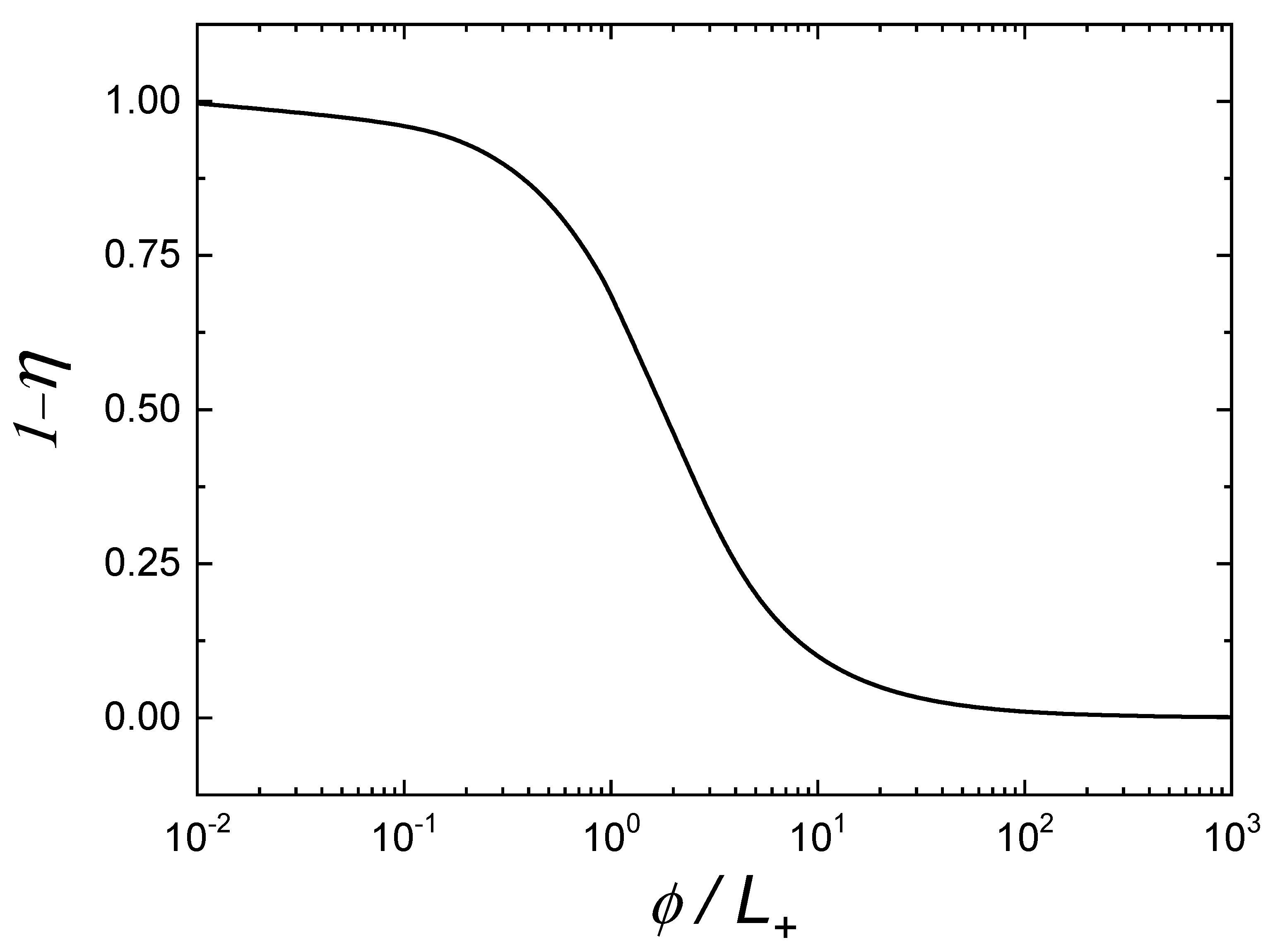
The authors declare no conflict of interest.

Appendix A

The parameter η describes the probability of an annihilation event inside a nanoparticle, and it depends on the ratio of the diameter ϕ of the particle and the positron diffusion length L + inside the NP, according to the Langevin function [51]:
η = coth ( ϕ L + ) L + ϕ .
Figure A1. The function (1 − η) gives an estimation of the positrons fraction that can reach the grain boundary with respect to those implanted in the grain.
Condensedmatter 06 00028 g0a1

References

  1. Pang, Q.; Kwok, C.Y.; Kundu, D.; Liang, X.; Nazar, L.F. Lightweight Metallic MgB2 Mediates Polysulfide Redox and Promises High-Energy-Density Lithium-Sulfur Batteries. Joule 2019, 3, 136–148. [Google Scholar] [CrossRef] [Green Version]
  2. Müller, V.; Bernhard, R.; Wegener, J.; Pfeiffer, J.; Rössler, S.; Scurtu, R.G.; Memm, M.; Danzer, M.A.; Wohlfahrt-Mehrens, M. Evaluation of Scalable Porous Si-Rich Si/C Composites with Low Volume Expansion in Coin Cells to Prismatic Cell Formats. Energy Technol. 2020, 8, 202000217. [Google Scholar] [CrossRef]
  3. Casino, S.; Niehoff, P.; Börner, M.; Winter, M. Protective coatings on silicon particles and their effect on energy density and specific energy in lithium ion battery cells: A model study. J. Energy Storage 2020, 29, 101376. [Google Scholar] [CrossRef]
  4. Okashy, S.; Luski, S.; Elias, Y.; Aurbach, D. Practical anodes for Li-ion batteries comprising metallurgical silicon particles and multiwall carbon nanotubes. J. Solid State Electrochem. 2018, 22, 3289–3301. [Google Scholar] [CrossRef]
  5. Langdon, J.; Manthiram, A. Crossover Effects in Batteries with High-Nickel Cathodes and Lithium-Metal Anodes. Adv. Funct. Mater. 2021, 31, 2010267. [Google Scholar] [CrossRef]
  6. Nanda, S.; Gupta, A.; Manthiram, A. Anode-Free Full Cells: A Pathway to High-Energy Density Lithium-Metal Batteries. Adv. Energy Mater. 2021, 11, 202000804. [Google Scholar] [CrossRef]
  7. Pagot, G.; Bertasi, F.; Vezzù, K.; Nawn, G.; Pace, G.; Nale, A.; Di Noto, V. Correlation between Properties and Conductivity Mechanism in Poly(vinyl alcohol)-based Lithium Solid Electrolytes. Solid State Ion. 2018, 320, 177–185. [Google Scholar] [CrossRef]
  8. Osada, I.; De Vries, H.; Scrosati, B.; Passerini, S. Ionic-Liquid-Based Polymer Electrolytes for Battery Applications. Angew. Chem. Int. Ed. 2016, 55, 500–513. [Google Scholar] [CrossRef] [PubMed]
  9. Bertasi, F.; Pagot, G.; Vezzù, K.; Nale, A.; Pace, G.; Herve Bang, Y.; Crivellaro, G.; Negro, E.; Di Noto, V. Lithiated Nanoparticles Doped with Ionic Liquids as Quasi-Solid Electrolytes for Lithium Batteries. Electrochim. Acta 2019, 307, 51–63. [Google Scholar] [CrossRef]
  10. Bertasi, F.; Pagot, G.; Vezzù, K.; Negro, E.; Sideris, P.J.; Greenbaum, S.G.; Ohno, H.; Scrosati, B.; Di Noto, V. Exotic solid state ion conductor from fluorinated titanium oxide and molten metallic lithium. J. Power Sources 2018, 400, 16–22. [Google Scholar] [CrossRef]
  11. Zewde, B.W.; Elia, G.A.; Admassie, S.; Zimmermann, J.; Hagemann, M.; Isfort, C.S.; Scrosati, B.; Hassoun, J. Polyethylene oxide electrolyte added by silane-functionalized TiO2 filler for lithium battery. Solid State Ion. 2014, 268, 174–178. [Google Scholar] [CrossRef]
  12. Bertasi, F.; Negro, E.; Vezzù, K.; Nawn, G.; Pagot, G.; Di Noto, V. Single-Ion-Conducting Nanocomposite Polymer Electrolytes for Lithium Batteries Based on Lithiated-Fluorinated-Iron Oxide and Poly(ethylene glycol) 400. Electrochim. Acta 2015, 175, 113–123. [Google Scholar] [CrossRef]
  13. Qiao, L.; Oteo, U.; Zhang, Y.; Peña, S.R.; Martínez-Ibañez, M.; Santiago, A.; Cid, R.; Meabe, L.; Manzano, H.; Carrasco, J.; et al. Trifluoromethyl-free anion for highly stable lithium metal polymer batteries. Energy Storage Mater. 2020, 32, 225–233. [Google Scholar] [CrossRef]
  14. Stettner, T.; Lingua, G.; Falco, M.; Balducci, A.; Gerbaldi, C. Protic Ionic Liquids-Based Crosslinked Polymer Electrolytes: A New Class of Solid Electrolytes for Energy Storage Devices. Energy Technol. 2020, 8, 2000742. [Google Scholar] [CrossRef]
  15. Martinez-Ibañez, M.; Sanchez-Diez, E.; Qiao, L.; Zhang, Y.; Judez, X.; Santiago, A.; Aldalur, I.; Carrasco, J.; Zhu, H.; Forsyth, M.; et al. Unprecedented Improvement of Single Li-Ion Conductive Solid Polymer Electrolyte Through Salt Additive. Adv. Funct. Mater. 2020, 30, 2000455. [Google Scholar] [CrossRef]
  16. Colombo, F.; Bonizzoni, S.; Ferrara, C.; Simonutti, R.; Mauri, M.; Falco, M.; Gerbaldi, C.; Mustarelli, P.; Ruffo, R. Polymer-in-Ceramic Nanocomposite Solid Electrolyte for Lithium Metal Batteries Encompassing PEO-Grafted TiO2 Nanocrystals. J. Electrochem. Soc. 2020, 167, 070535. [Google Scholar] [CrossRef] [Green Version]
  17. Zeng, X.; Zhan, C.; Lu, J.; Amine, K. Stabilization of a High-Capacity and High-Power Nickel-Based Cathode for Li-Ion Batteries. Chem 2018, 4, 690–704. [Google Scholar] [CrossRef] [Green Version]
  18. Cui, Z.; Xie, Q.; Manthiram, A. Zinc-Doped High-Nickel, Low-Cobalt Layered Oxide Cathodes for High-Energy-Density Lithium-Ion Batteries. ACS Appl. Mater. Interfaces 2021, 13, 15324–15332. [Google Scholar] [CrossRef]
  19. Pagot, G.; Bandiera, M.; Vezzù, K.; Migliori, A.; Bertoncello, R.; Negro, E.; Morandi, V.; Di Noto, V. High valence transition metal-doped olivine cathodes for superior energy and fast cycling lithium batteries. J. Mater. Chem. A 2020, 8, 25727–25738. [Google Scholar] [CrossRef]
  20. Pagot, G.; Bertasi, F.; Nawn, G.; Negro, E.; Bach Delpeuch, A.; Vezzù, K.; Cristofori, D.; Di Noto, V. Effect of Graphite and Copper Oxide on the Performance of High Potential Li[Fe1/3Ni1/3Co1/3]PO4 Olivine Cathodes for Lithium Batteries. Electrochim. Acta 2017, 225, 533–542. [Google Scholar] [CrossRef]
  21. Schmiegel, J.P.; Qi, X.; Klein, S.; Winkler, V.; Evertz, M.; Nölle, R.; Henschel, J.; Reiter, J.; Terborg, L.; Fan, Q.; et al. Improving the cycling performance of high-voltage NMC111 || graphite lithium ion cells by an effective urea-based electrolyte additive. J. Electrochem. Soc. 2019, 166, A2910–A2920. [Google Scholar] [CrossRef]
  22. Helbig, J.; Beuse, T.; Siozios, V.; Placke, T.; Winter, M.; Schmuch, R. Finding the sweet spot: Li/Mn-rich cathode materials with fine-tuned core–shell particle design for high-energy lithium ion batteries. Electrochim. Acta 2021, 366, 137413. [Google Scholar] [CrossRef]
  23. Pagot, G.; Bertasi, F.; Nawn, G.; Negro, E.; Carraro, G.; Barreca, D.; Maccato, C.; Polizzi, S.; Di Noto, V. High-Performance Olivine for Lithium Batteries: Effects of Ni/Co Doping on the Properties of LiFeαNiβCoγPO4 Cathodes. Adv. Funct. Mater. 2015, 25, 4032–4037. [Google Scholar] [CrossRef]
  24. Yang, S.; Zhou, S.; Hua, Y.; Zhou, X.; Liu, X.; Pan, Y.; Ling, H.; Wu, B. A parameter adaptive method for state of charge estimation of lithium-ion batteries with an improved extended Kalman filter. Sci. Rep. 2021, 11, 1–15. [Google Scholar] [CrossRef]
  25. Chen, J.; Feng, X.; Jiang, L.; Zhu, Q. State of charge estimation of lithium-ion battery using denoising autoencoder and gated recurrent unit recurrent neural network. Energy 2021, 227, 120451. [Google Scholar] [CrossRef]
  26. Sihvo, J.; Roinila, T.; Stroe, D.I. Novel Fitting Algorithm for Parametrization of Equivalent Circuit Model of Li-Ion Battery from Broadband Impedance Measurements. IEEE Trans. Ind. Electron. 2021, 68, 4916–4926. [Google Scholar] [CrossRef]
  27. Ma, L.; Hu, C.; Cheng, F. State of Charge and State of Energy Estimation for Lithium-Ion Batteries Based on a Long Short-Term Memory Neural Network. J. Energy Storage 2021, 37, 102440. [Google Scholar] [CrossRef]
  28. Dupasquier, A.; Ferragut, R.; Iglesias, M.M.; Massazza, M.; Riontino, G.; Mengucci, P.; Barucca, G.; Macchi, C.E.; Somoza, A. Hardening nanostructures in an AlZnMg alloy. Philos. Mag. 2007, 87, 3297–3323. [Google Scholar] [CrossRef] [Green Version]
  29. Gidley, D.W.; Peng, H.-G.; Vallery, R.S. Positron Annihilation As A Method To Characterize Porous Materials. Annu. Rev. Mater. Res. 2006, 36, 49–79. [Google Scholar] [CrossRef] [Green Version]
  30. Puska, M.J.; Nieminen, R.M. Theory of positrons in solids and on solid surfaces. Rev. Mod. Phys. 1994, 66, 841–897. [Google Scholar] [CrossRef] [Green Version]
  31. Tuomisto, F.; Makkonen, I. Defect identification in semiconductors with positron annihilation: Experiment and theory. Rev. Mod. Phys. 2013, 85, 1583–1631. [Google Scholar] [CrossRef] [Green Version]
  32. Schultz, P.J.; Lynn, K.G. Interaction of positron beams with surfaces, thin films, and interfaces. Rev. Mod. Phys. 1988, 60, 701–779. [Google Scholar] [CrossRef]
  33. Canesi, E.V.; Binda, M.; Abate, A.; Guarnera, S.; Moretti, L.; D’Innocenzo, V.; Sai Santosh Kumar, R.; Bertarelli, C.; Abrusci, A.; Snaith, H.; et al. The effect of selective interactions at the interface of polymer–oxide hybrid solar cells. Energy Environ. Sci. 2012, 5, 9068–9076. [Google Scholar] [CrossRef]
  34. Barbiellini, B.; Kuriplach, J. Advanced characterization of lithium battery materials with positrons. J. Phys. Conf. Ser. 2017, 791, 012016. [Google Scholar] [CrossRef] [Green Version]
  35. Klinser, G.; Kren, H.; Koller, S.; Würschum, R. Operando monitoring of charging-induced defect formation in battery electrodes by positrons. Appl. Phys. Lett. 2019, 114, 013905. [Google Scholar] [CrossRef]
  36. Klinser, G.; Topolovec, S.; Kren, H.; Koller, S.; Krenn, H.; Würschum, R. Charging of lithium cobalt oxide battery cathodes studied by means of magnetometry. Solid State Ion. 2016, 293, 64–71. [Google Scholar] [CrossRef]
  37. Parz, P.; Fuchsbichler, B.; Koller, S.; Bitschnau, B.; Mautner, F.-A.; Puff, W.; Würschum, R. Charging-induced defect formation in LixCoO2 battery cathodes studied by positron annihilation spectroscopy. Appl. Phys. Lett. 2013, 102, 151901. [Google Scholar] [CrossRef]
  38. Würschum, R.; Topolovec, S.; Klinser, G.; Sprengel, W.; Kren, H.; Koller, S.; Krenn, H.; Hugenschmidt, C.; Reiner, M.; Gigl, T.; et al. Defects and Charging Processes in Li-Ion Battery Cathodes Studied by Operando Magnetometry and Positron Annihilation. Mater. Sci. Forum 2017, 879, 2125–2130. [Google Scholar] [CrossRef]
  39. Kuriplach, J.; Barbiellini, B. Parameter-Free Gradient Correction for Positron States in Oxides. Defect Diffus. Forum 2017, 373, 35–40. [Google Scholar] [CrossRef]
  40. Lin, Q.; Li, Q.a.; Gray, K.E.; Mitchell, J.F. Vapor Growth and Chemical Delithiation of Stoichiometric LiCoO2 Crystals. Cryst. Growth Des. 2012, 12, 1232–1238. [Google Scholar] [CrossRef]
  41. Calloni, A.; Dupasquier, A.; Ferragut, R.; Folegati, P.; Iglesias, M.M.; Makkonen, I.; Puska, M.J. Positron localization effects on the Doppler broadening of the annihilation line: Aluminum as a case study. Phys. Rev. B 2005, 72, 054112. [Google Scholar] [CrossRef] [Green Version]
  42. Brandt, W. Positron dynamics in solids. Appl. Phys. 1974, 5, 1–23. [Google Scholar] [CrossRef]
  43. Barbiellini, B.; Suzuki, K.; Orikasa, Y.; Kaprzyk, S.; Itou, M.; Yamamoto, K.; Wang, Y.J.; Hafiz, H.; Yamada, R.; Uchimoto, Y.; et al. Identifying a descriptor for d-orbital delocalization in cathodes of Li batteries based on x-ray Compton scattering. Appl. Phys. Lett. 2016, 109, 073102. [Google Scholar] [CrossRef] [Green Version]
  44. Cartier, E.; Heinrich, F.; Pfluger, P.; Güntherodt, H.J. Positron Annihilation in Graphite Intercalation Compounds. Phys. Rev. Lett. 1981, 46, 272–275. [Google Scholar] [CrossRef]
  45. Veen, A.V.; Schut, H.; Vries, J.D.; Hakvoort, R.A.; Ijpma, M.R. Analysis of positron profiling data by means of “VEPFIT”. AIP Conf. Proc. 1991, 218, 171–198. [Google Scholar] [CrossRef]
  46. Consolati, G.; Ferragut, R.; Galarneau, A.; Di Renzo, F.; Quasso, F. Mesoporous materials for antihydrogen production. Chem. Soc. Rev. 2013, 42, 3821–3832. [Google Scholar] [CrossRef]
  47. Kansy, J. Microcomputer program for analysis of positron annihilation lifetime spectra. Nucl. Instrum. Methods Phys. Res. Sect. A Accel. Spectrometers Detect. Assoc. Equip. 1996, 374, 235–244. [Google Scholar] [CrossRef]
  48. Panzarasa, G.; Aghion, S.; Soliveri, G.; Consolati, G.; Ferragut, R. Positron annihilation spectroscopy: A new frontier for understanding nanoparticle-loaded polymer brushes. Nanotechnology 2015, 27, 02LT03. [Google Scholar] [CrossRef] [PubMed]
  49. Shi, W.; Callewaert, V.; Barbiellini, B.; Saniz, R.; Butterling, M.; Egger, W.; Dickmann, M.; Hugenschmidt, C.; Shakeri, B.; Meulenberg, R.W.; et al. Nature of the Positron State in CdSe Quantum Dots. Phys. Rev. Lett. 2018, 121, 057401. [Google Scholar] [CrossRef] [Green Version]
  50. Suzuki, K.; Suzuki, S.; Otsuka, Y.; Tsuji, N.; Jalkanen, K.; Koskinen, J.; Hoshi, K.; Honkanen, A.-P.; Hafiz, H.; Sakurai, Y.; et al. Redox oscillations in 18650-type lithium-ion cell revealed by in operando Compton scattering imaging. Appl. Phys. Lett. 2021, 118, 161902. [Google Scholar] [CrossRef]
  51. Dryzek, J.; Czapla, A.; Kusior, E. Positron annihilation studies of the multilayer system. J. Phys. Condens. Matter 1998, 10, 10827–10838. [Google Scholar] [CrossRef]
Figure 1. (a) Powder wide-angle X-ray diffractogram of pristine LCO material. hkl indices are reported into the figure on the top of the corresponding peaks. (b,c) HR-TEM images and (d) SAD pattern of the LCO material. The particle size distribution obtained from TEM images for this material is reported in the inset of Figure 1b.
Condensedmatter 06 00028 g001
Figure 2. Schematic set-up for the LiXCoO2 measurements. (a) PALS measurements using a sandwich configuration; here, the positrons are emitted from the 22Na source located between two Kapton foils (7.5 μm each). In this case, positrons are emitted with a continuous distribution of kinetic energies up to 546 keV. (b) Doppler measurements using a positron beam with variable implantation energy. Each Doppler measurement is performed with a fixed energy with positrons implanted with a range of kinetic energies from 1 to 17 keV. In this case, the maximum mean implantation depth is about 1 μm.
Condensedmatter 06 00028 g002
Figure 3. Evolution of the S parameter as a function of the positron implantation energy (mean implantation depth, upper frame) in LiCoO2 (green symbols), in Li0.5CoO2 (brown symbols) and in a graphite reference sample (black dashed line). The VEPFIT fitting (green and brown dashed lines) gives an estimation of the positron diffusion length.
Condensedmatter 06 00028 g003
Table 1. Reference materials especially relevant for the lifetime analysis. The cathodes were deposited on the Al foil. The Al foil results are compared with an Al polycrystal sample of high purity (99.999%) after a thermal treatment. The graphite powder used in the cathode preparation was sintered and measured.
Referencesτ1 (ps)τ2 (ps)I1 (%)I2 (%)τbulk (ps)τav (ps)
Al foil (rolled)60 (5)228 (3)15 (2)85 (2)162 (4)208 (3)
Al (polycrystallyne)158 (1)234 (3)96 (1)4 (2)161 (2)162 (2)
Graphite (C)107 (4)400 (5)13 (3)87 (2)-362 (5)
Table 2. Thickness, positron lifetime components, relative intensities and average positron lifetime obtained in the cathode oxides. The initial thickness of the LiCoO2 and graphite/PVDF mixture is the same 59 (2) nm, after the charge process the macroscopic thickness is increased about 14% in the case of the mixture with Li0.5CoO2 grains.
CathodeThickness (μm)τ1 (ps)τ2 (ps)I1 (%)I2 (%)τav (ps)
LiCoO259 (2)163 (2)315 (3)66 (2)34 (2)215 (4)
Li0.5CoO267 (2)181 (2)327 (3)73 (2)27 (2)220 (4)
Table 3. Positron diffusion length and S parameter of the surface and bulk.
CathodeL+ (nm)SsurfaceSbulk
LiCoO260 (3)0.506 (1)0.4760 (7)
Li0.5CoO255 (3)0.505 (1)0.4742 (7)
Publisher’s Note: MDPI stays neutral with regard to jurisdictional claims in published maps and institutional affiliations.

