Autonomous System for Wildfire and Forest Fire Early Detection and Control


Department of Electrical and Computer Engineering, ISR—Institute of Systems and Robotics, University of Coimbra, Rua Sílvio Lima—Pólo II, 3030-290 Coimbra, Portugal
*
Author to whom correspondence should be addressed.
Inventions 2020, 5(3), 41; https://0-doi-org.brum.beds.ac.uk/10.3390/inventions5030041
Submission received: 29 June 2020
/
Revised: 7 August 2020
/
Accepted: 17 August 2020
/
Published: 19 August 2020
(This article belongs to the Special Issue New Developments of Electrical Machines and Motor Drives)
Abstract
:Recurring and increasing large-scale wildfires across the globe (e.g., Southern Europe, California, Australia), as a result of worsening climate conditions with record temperatures, drought, and strong winds, present a challenge to mankind. Early fire detection is crucial for a quick reaction and effective firefighting operations, minimizing the risk to human lives as well as the destruction of assets, infrastructures, forests, and wildlife. Usually, ground firefighting relies on human intervention and dangerous exposition to high temperatures and radiation levels, proving the need for mechanisms and techniques to remotely or autonomously detect and combat fire. This paper proposes an autonomous firefighting system built with a motorized water turret, narrow beam far infrared (FIR) sensors, and a micro-controller running novel algorithms and techniques. Experimental field results validated the technical approach, indicating that when a small fire front is within the field of view of the FIR sensor and within the range of the water jet, it is possible to provide an early alarm and even autonomously extinguish or delay the approaching fire front, increasing the chance for evacuation.
1. Introduction
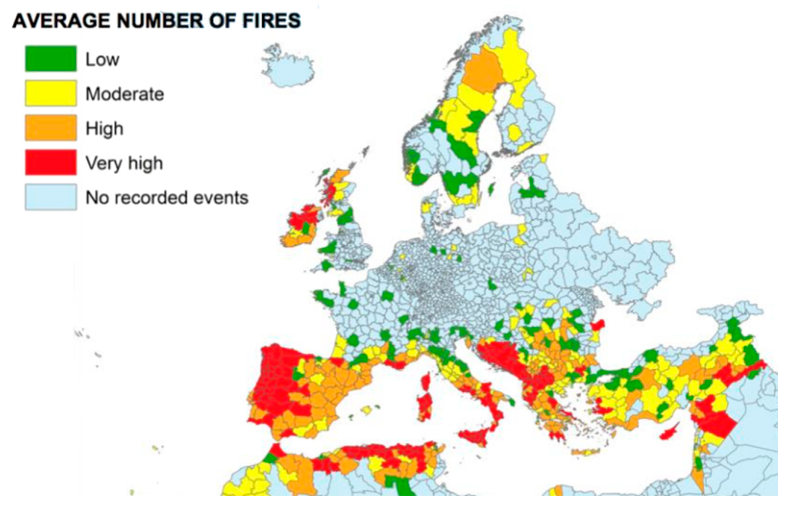
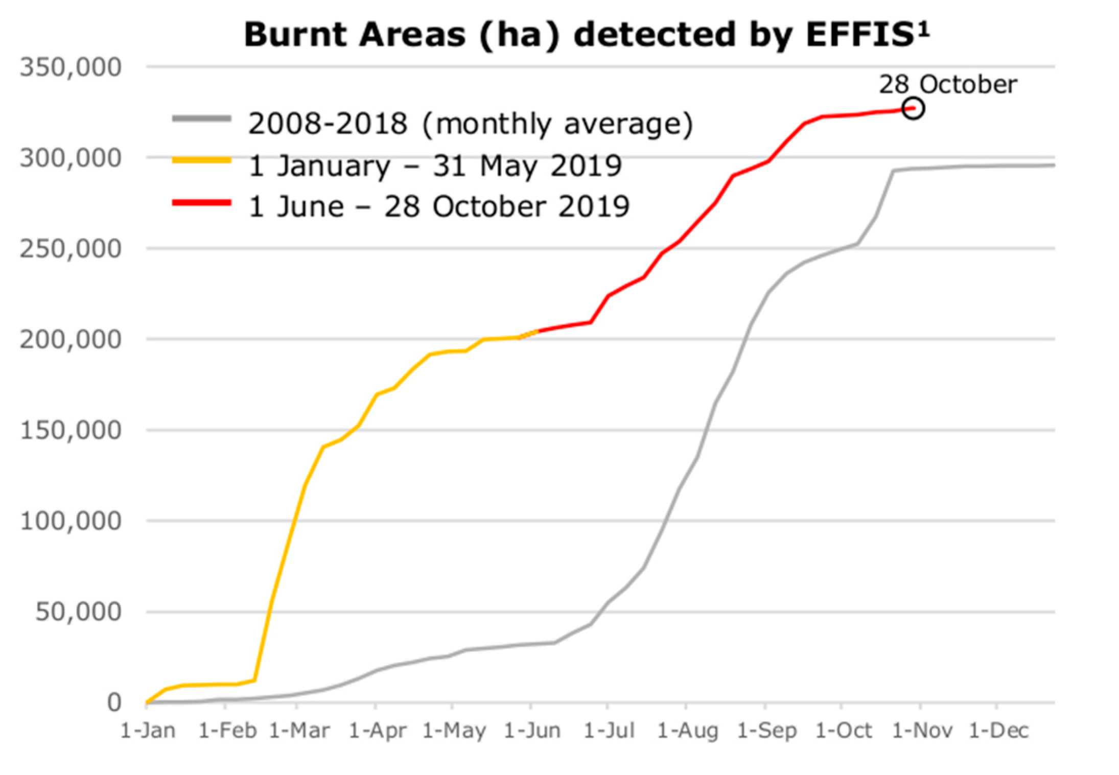
Over the past years, wildfires have become increasingly common, larger, and deadlier. The associated costs and losses also increased, representing billions of dollars in natural resources and property loss (p. 7, [1]). Recent climatic conditions are also to blame, because high temperatures, low precipitation, and regular strong winds favor the desiccation of vegetation, potentiating ignition and fire spread (p. 5, [2]). In the beginning of the millennia (2000), it was estimated that about 50,000 fires occur each year in the Mediterranean basin, affecting more than 600,000 ha (p. preface, [2]). According to the “Mediterranean Forestry Action Programme (FAO 1993)”, between 1981 and 1997, Portugal, on average, had an area of 83,143 ha burned per year, representing 2.79% of the national forested area affected by fire (p. 8, [2]). However, in 2017, in Portugal alone, forest fires burned 442,400 ha (1,093,194 acres) of rural and urban areas [3], which corresponds to 4.8% of the total country’s area. Please refer to Figure 1 for an overview of the average number of fires between 2000 and 2017 and Figure 2 for a comparison of the average burnt areas between 2008–2018 and 2019). A similar situation occurred in the state of California, where the 2018 wildfires burned 676,300 ha (1,671,214 acres) [4], caused billions of dollars in losses, and cost hundreds of lives. This recent recurring occurrence of cataclysmic wildfires across the globe, as a result of worsening climate conditions with record temperatures, drought, and strong winds, presents a challenge to minimize the risk to human lives as well as the destruction of assets, infrastructures, forests, and wildlife. As a result of climate change, forest fire risk is increasing globally, with areas such as Canada, Alaska, and Siberia being subject to large fires.
Early fire detection is critical for firefighting operations and population evacuation with a good chance of success. Unfortunately, early stage fire detection is rare, because monitoring and reports are usually made by humans, who rely on eyesight to detect smoke columns, which is often too late to allow the effective deployment of counter measures toward fire confinement. The general population is also at risk, in particular when a massive fire strikes without warning, rendering evacuation difficult or impossible.
On the last line of defense, current firefighting mechanisms almost always rely on direct control and handling by firefighters, who become exposed to the dangers of fire and harsh conditions such as high temperature and thermal radiation levels. Therefore, it is necessary to develop mechanisms and techniques to remotely or autonomously detect and deploy fire countermeasures anywhere.
Forest biomass (the “fuel”) exchanges moisture with the air, in particular, light fuels, such as pine needles or dry vegetation which react quickly to changes in the relative humidity (RH) of the air, so when the RH drops, these materials dry quickly, literally providing support for a quick fire spread. Thicker woody fuels (bark, shrubs, branches, and foliage) either green or dead (dry), also react to variations of air RH, although at a slower pace because of their larger mass. However, an extended exposure to high temperatures, low precipitation, and regular winds favor their desiccation, contributing to potential ignition and fire spread risks.
When wood is exposed to heat, some of its cellulose material compound molecules break apart, promoting the release of gases such as CH2O (formaldehyde), a.k.a. methanal, which has a flash point of 50–60 °C [7] (Flash Point: “the lowest temperature at which a substance vaporizes into a gas, which can be ignited with the introduction of an external source of fire”). Given enough concentration of that gas, a small flame or spark may be all it takes to start a self-sustaining reaction, i.e., when these gases ignite, more heat is released, promoting the release and ignition of even more gases, eventually heating the wood until its ignition temperature: 260 °C (Ignition Temperature: “the lowest temperature at which a volatile material will be vaporized into a gas which ignites without the help of any external flame or ignition source”). At this point, wood’s compound molecules break apart and react with oxygen, producing flames and releasing heat, light, H2O, CO2, CO, and C, among others [8,9]. Ashes are formed by components found in wood that remain solid, such as silica, potassium and phosphorus. Fire will grow and spread as long as there is high temperature, fuel, and oxygen around it.
36C10H15O7 + 5O2 + heat → 2C50H10O + 260CH2O
[wood] + [oxygen] + [heat] → [charred wood] + [formaldehyde]
[wood] + [oxygen] + [heat] → [charred wood] + [formaldehyde]
6CH2O + 3O2 → 6H2O + 2CO2 + 2CO + 2C + heat + light
[formaldehyde] + [oxygen] → [water] + [carbon dioxide] + [carbon monoxide] +
[carbon] + [heat] + [light]
[formaldehyde] + [oxygen] → [water] + [carbon dioxide] + [carbon monoxide] +
[carbon] + [heat] + [light]
Fire and its effects can be detected with different types of technologies and sensors, such as temperature sensors, gas sensors (CO2, CO), optical smoke detectors, and also by analyzing specific bands of the electromagnetic spectrum, such as infrared, visible, and ultra-violet.
“Regular” thermal sensors, i.e., thermistors, thermocouples, resistance thermometers, or silicon bandgap temperature sensors, despite being reliable and precise, are not useful in the detection of an actual wildfire from a distance. However, a regular temperature sensor, associated with a humidity sensor, can be used to calculate the temperature and relative humidity (RH) of the air, which in turn gives valuable information regarding the fire risks [10].
Gas sensors, for CO and CO2, and optical smoke detectors can also be used to detect fire, but they require concentration levels that may never be reached in the open air, or that can be strongly influenced by wind, failing early detection even if a fire is just a few meters away. Gas sensors may also lack long-term stability and are subject to cross-sensitivities and false alarms [11].
Human or automated image-based detection of fire or smoke, in the visible spectrum, is possible, even at long distances [12,13], but only after fire has passed its initial ignition stage, and it may require multiple observation points to pinpoint a fire front on the terrain.
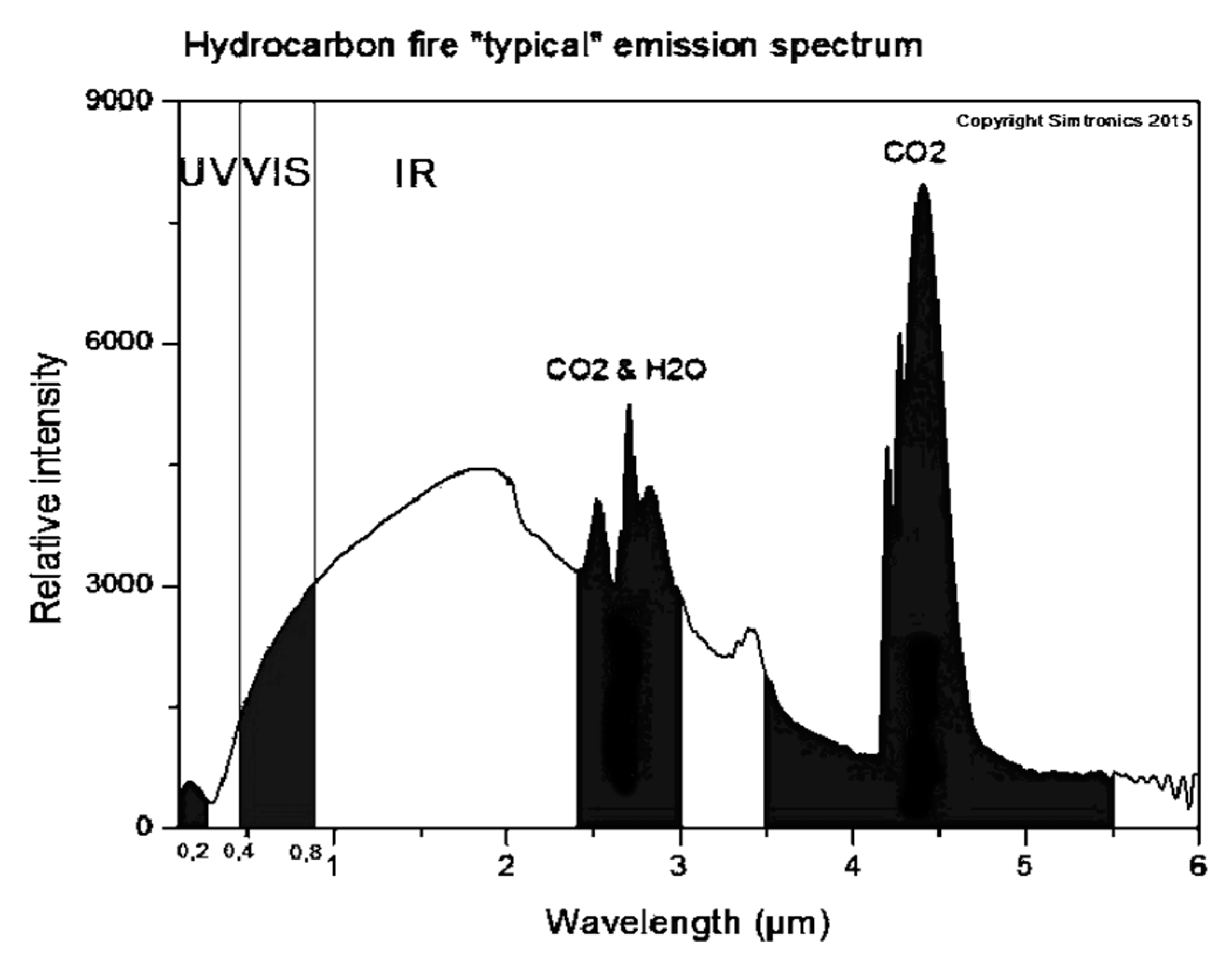
When analyzing the radiation intensity produced by fire across the spectrum Figure 3, we can observe some UV radiation (10–400 nm), but most of the fire radiation is concentrated in the visible (400–750 nm), near-infrared (NIR) (0.75–1.4 µm), short-wavelength infrared (SWIR) (1.4–3 µm), and mid-wavelength infrared (MWIR) (3–8 µm). In fact, in the SWIR and MWIR, we can observe a hydrocarbon fuel burn signature with peaks associated with CO2 and H2O at around 2.9 µm and 4.3 µm.
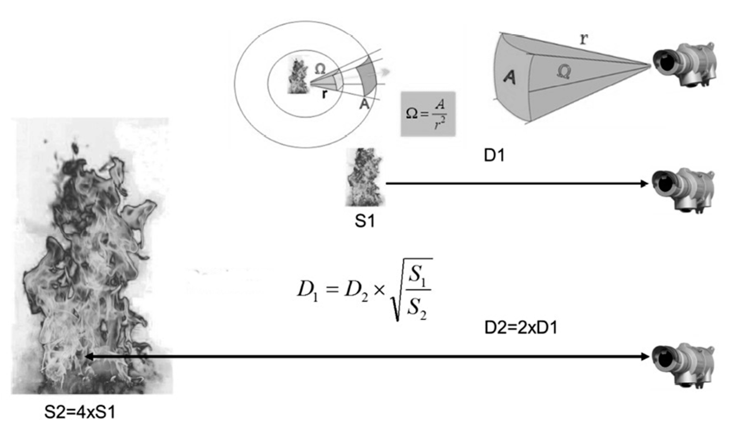
IR detection alone is efficient in the remote detection of hot temperatures, such as fire, through smoke and even some vegetation. Narrow field-of-view sensors are ideal to pinpoint hot points at long distances in a specific direction. However, apart from the amplitude, it is difficult to differentiate a distant fire from a close warm object, or even the sun on the horizon. As IR sensors have a specific field of view, the measured temperature equals the average temperature captured in its solid angle. Hence, a small, far away, and very hot spot may provide the same radiation sum as a closer, larger, and slightly warm object. Similarly, a large fire at a distance may provide the same radiation as a closer smaller fire. For example, as seen in Figure 4, the captured radiation of fire with intensity S1 at distance D1 is similar to the captured radiation of fire with intensity S2 = 4 × S1 at distance D2 = 2 × D1.
In the open air, wood flames flicker randomly, and they are usually modulated from 1 to 20 Hz [14]. This second signature can be used to differentiate an actual fire from a hot object in the background, complementing other sensing technologies. Ideally, optical radiation sensors used for the detection of fire should detect broad spectral IR bands and also specific wavelengths (2.9 µm, 4.3 µm…) in order to filter background radiation and false positives.
Sensors that can be used to detect fire vary in their detection coverage area, sensitivity versus distance, complexity, cost, and most importantly their reliability, including stability and performance over extended periods of time. Several authors have proposed the use of wireless sensor networks for forest fire detection [15,16,17] as a possible solution to help detect the occurrence of forest fires early. One of the main difficulties is the lack of low-cost thermal image sensors that can be used in combination with wireless sensor networks.
This paper proposes a low-cost autonomous firefighting system, by combining a motorized water turret, an advanced sensory unit with a matrix of narrow beam far infrared (FIR) sensors, and a micro-controller. This paper also presents software-defined autonomous firefighting algorithms and techniques integrated into the proposed hardware system.
2. Materials and Methods
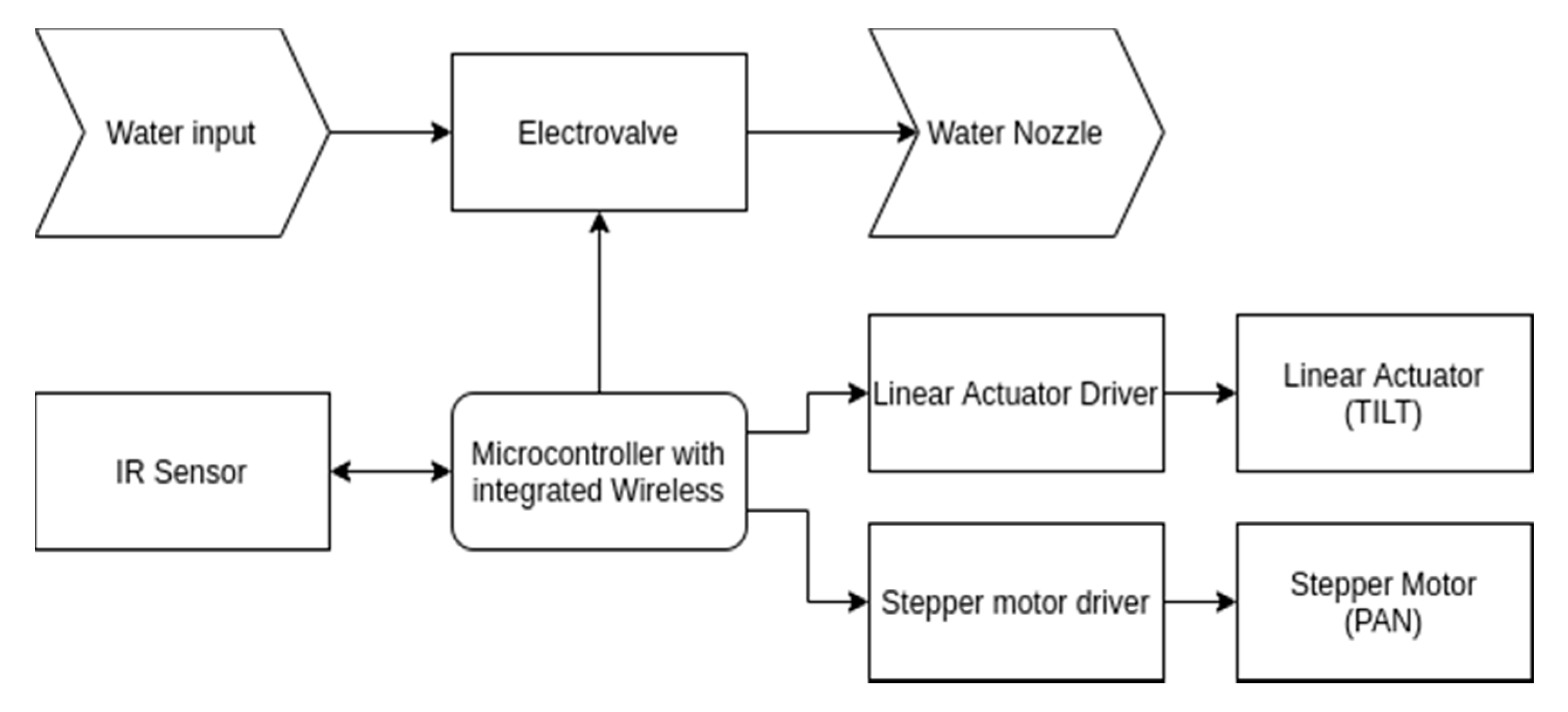
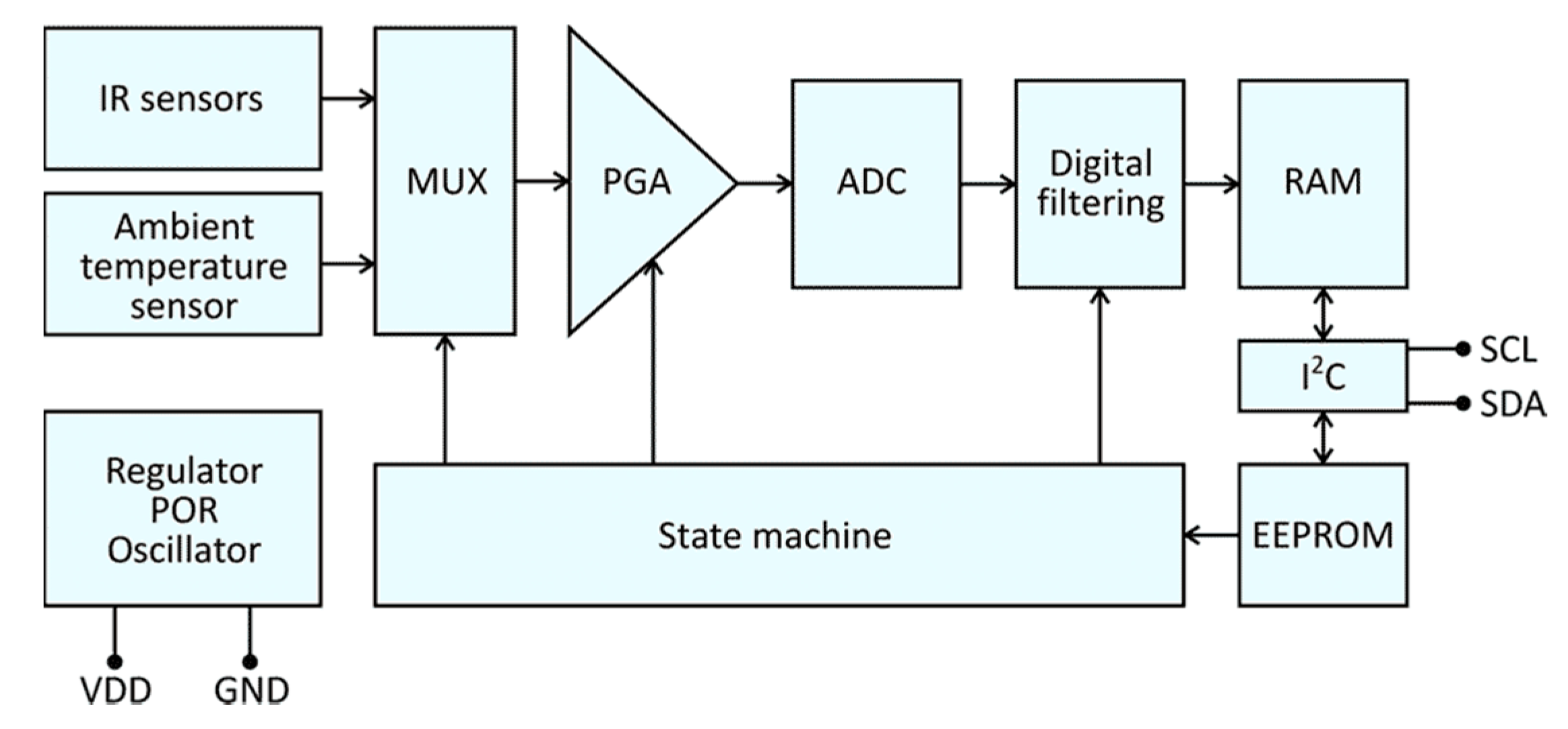
The simplified hardware functional block diagram is depicted in Figure 5. A firefighter nozzle was coupled to a motorized pan and tilt unit and a solenoid valve. A low-cost compact far infrared (FIR) thermal sensor array with a resolution of 32 × 24 and a field of view (FoV) of 55° × 35° (block diagram depicted in Figure 6) built by Melexis was connected to a 32 bit micro-controller with integrated wireless communication capability, which also controlled the pan and tilt unit and the solenoid valve, providing remote wireless monitoring and control. According to Melexis, the IR sensor manufacturer: “…This infrared (IR) sensor offers a cost-effective alternative to more expensive high-end thermal cameras. This 32 × 24 pixel device is suited to safety and convenience applications that include fire prevention systems … has a −40 °C to 85 °C operational temperature range and can measure object temperatures between −40 and 300 °C. Maintaining high levels of precision across its full measurement scale, this infrared sensor delivers a typical target object temperature accuracy of ±1 °C. It also exhibits superior noise performance. Unlike microbolometer alternatives, the sensor does not need frequent re-calibration, thus ensuring continuous monitoring and lowering the system cost. The Melexis MLX90640 is supplied in a compact, 4-pin TO39 package incorporating the requisite optics…” (source: https://www.melexis.com/en/product/MLX90640/Far-Infrared-Thermal-Sensor-Array).
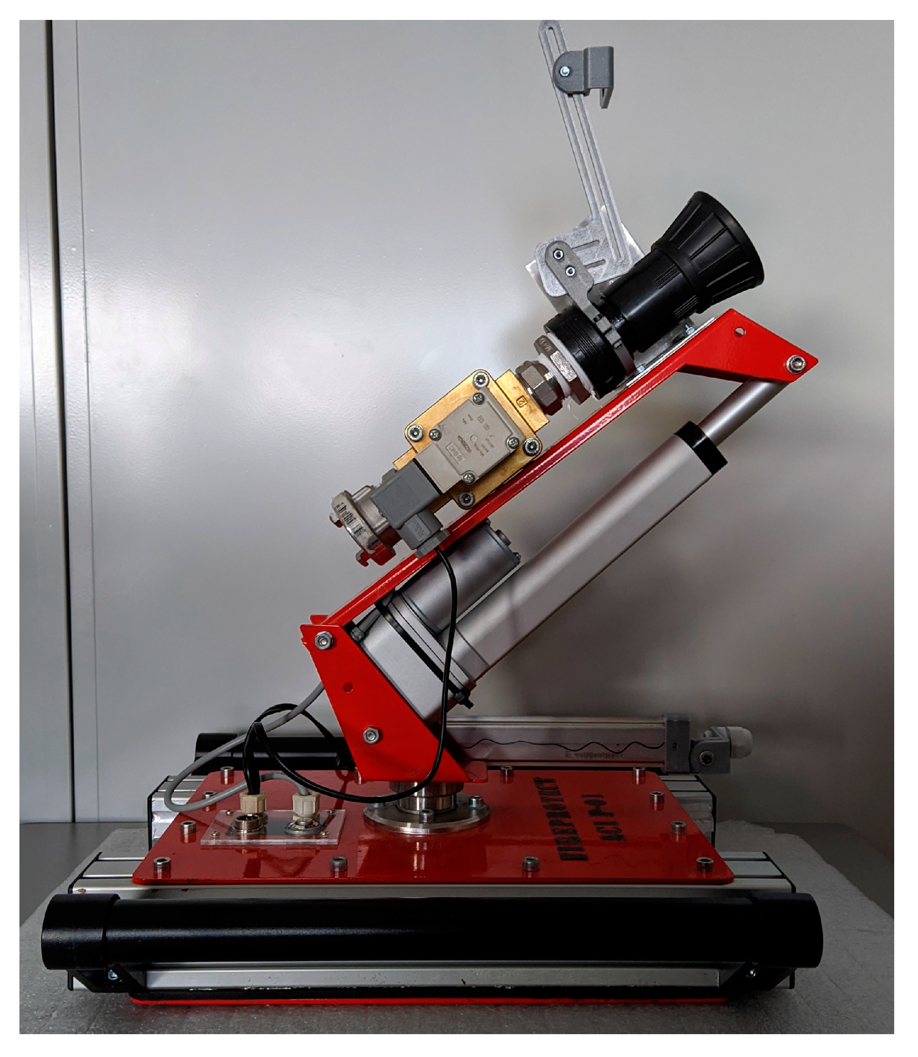
In the first experiments, the IR sensor was mounted to the side of the nozzle, in the horizontal plane of the center of the jet, and moved (pan and tilt) in solidarity with it Figure 7. On later experiments, the IR sensor was mounted under the nozzle, near the base, in the same vertical plane as the center of the jet, at a constant tilt, panning in solidarity with the nozzle. With this system, we could remotely control the pan, tilt, and activate the water jet. The cone opening of the water jet was set manually at a constant position that provided up to 15–20 m of range with 7 bar of water pressure.
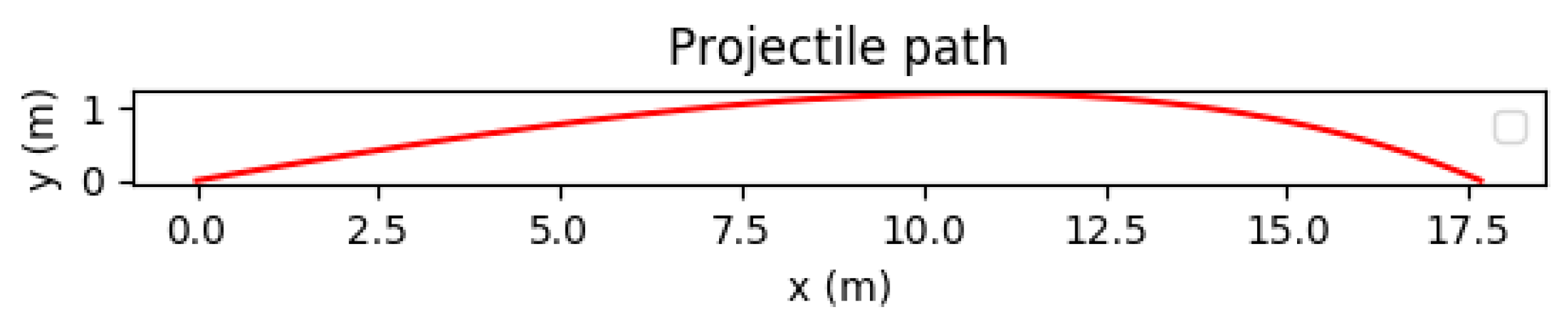
The parabola and range of the water jet depend on the exit angle, pressure, aperture, and flow through the nozzle. A study was made to preview the shape and range of the water jet parabola based on water pressure and exit angle; however, as the water jet shape can be diverted and spread by wind, these variables alone cannot be used to preview the hit point of the jet. Figure 8 depicts a preview of the parabolic trajectory of a water jet with the following assumptions: our water jet acts as a stream of water spheres with a radius of 2.5 cm and 8 g each, launched with an angle of 10°, at a speed of 40 m/s. Assuming a drag coefficient of 0.5, and assuming there is no dispersion nor wind, we should get a horizontal range of around 17.5 m, a maximum height of 1.2 m, and a time of flight of approximately 1 s.
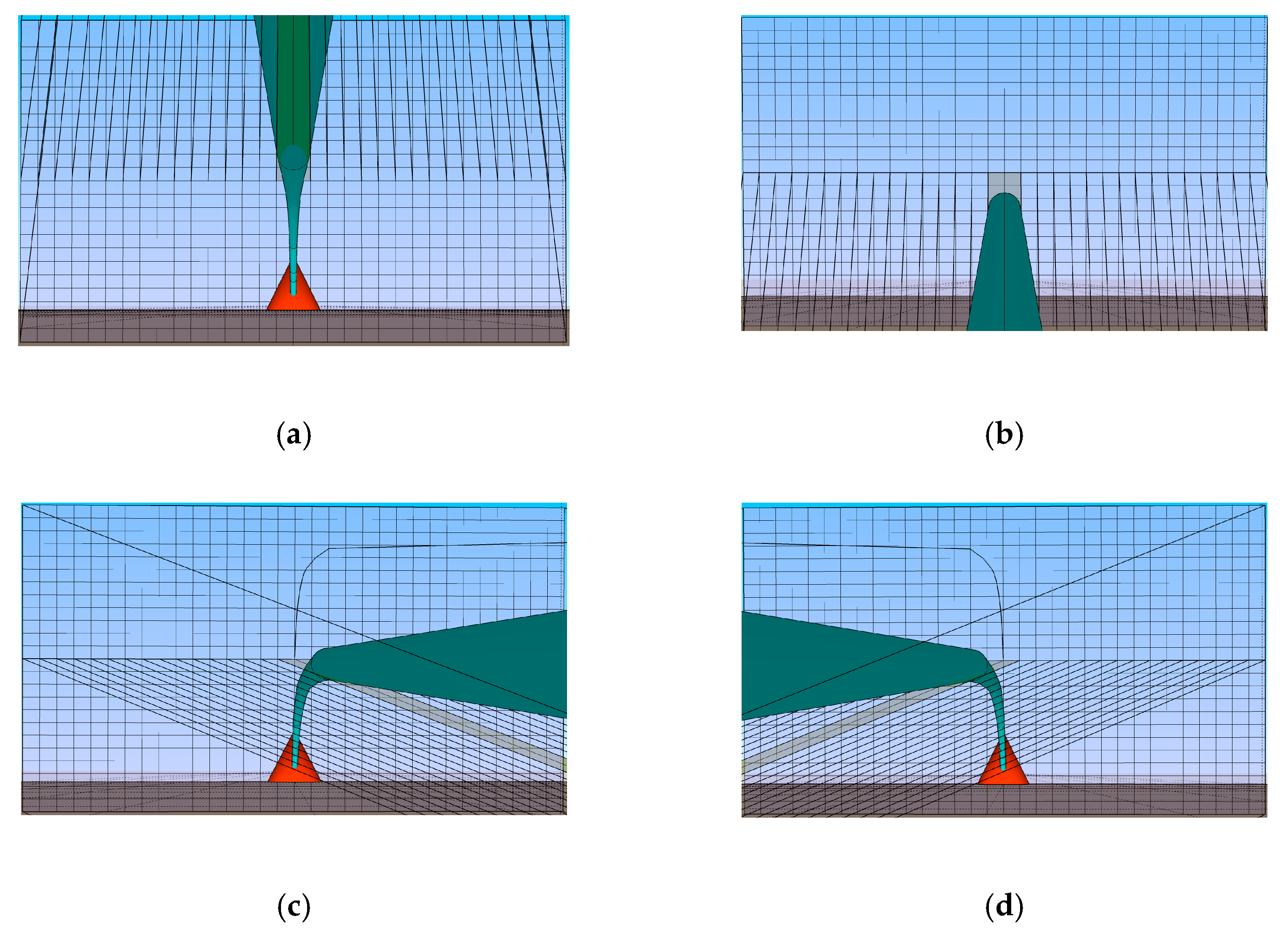
This time of flight presents a challenge for automated control, as every action on the pan and tilt unit has a delayed effect on the water hit point. Wind also presents additional challenge, particularly with low pressures, as the water cone can spread randomly or be diverted. Water, either on the jet or as mist in the air, also attenuates or even blocks part of the view of the IR sensor, as depicted in Figure 9. This presents additional challenges but also opportunities, as it can be used to locate the fire front, as can be seen later in the discussion section.
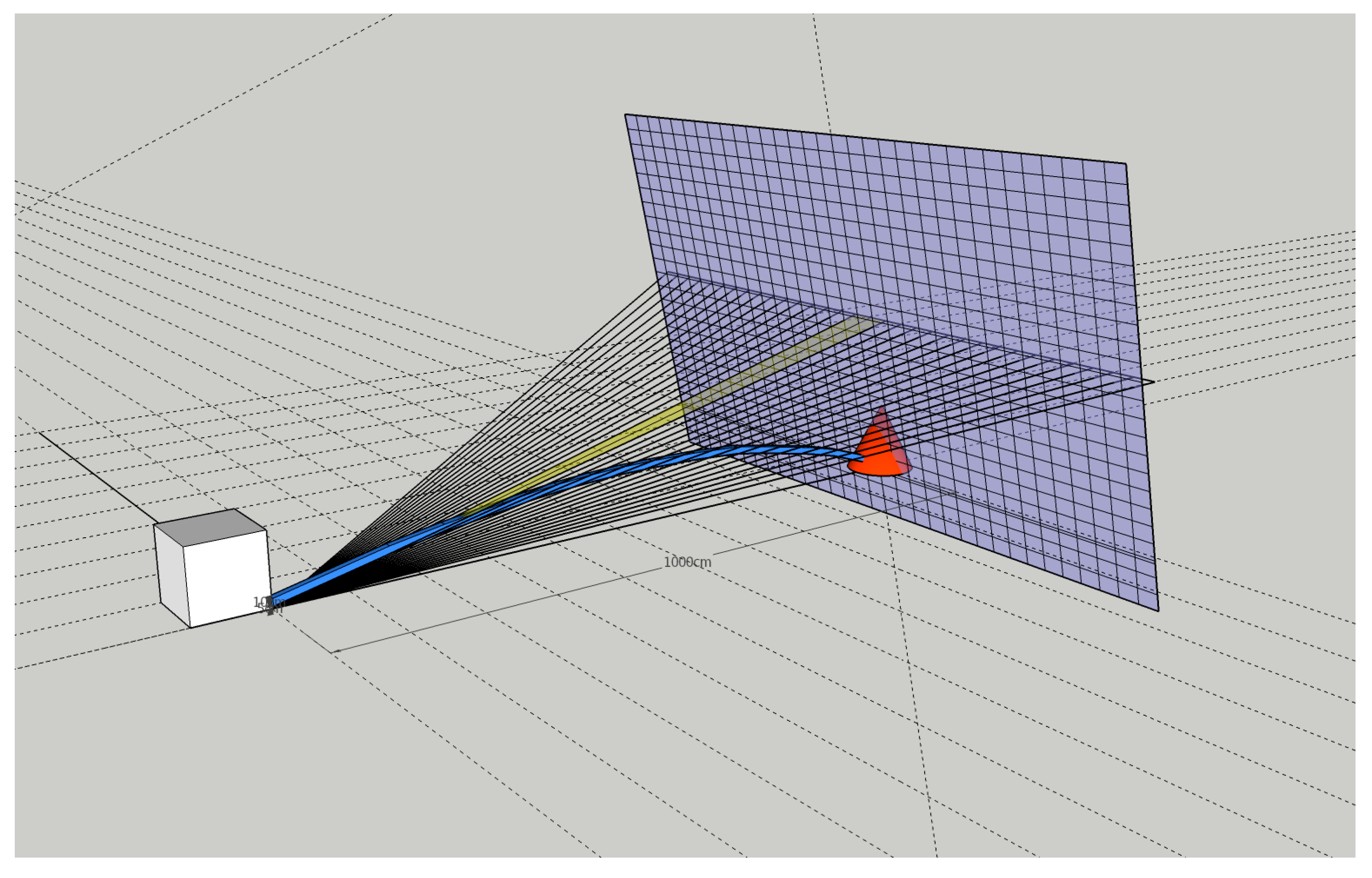
Simulations were made to visualize the solid angles and projection matrix of the IR sensor at a distance. Figure 10 depicts the simulation of a target at 10 m hit by a cylindrical jet, which was launched with an exit angle of 13°, covering a parabolic trajectory with no dispersion. The far matrix denotes the view per pixel, and the radial lines denote the central plane of the sensor. The simulated FoV is 35° with the sensor mounted at the tip of the nozzle. Figure 9 repeats the simulation from the point of view of the IR sensor mounted at different positions. Table 1 describes the IR sensor full matrix versus pixel Field of View (FoV) per plane, and Table 2 describes the covered width and height as a function of distance from the IR sensor.
3. Results
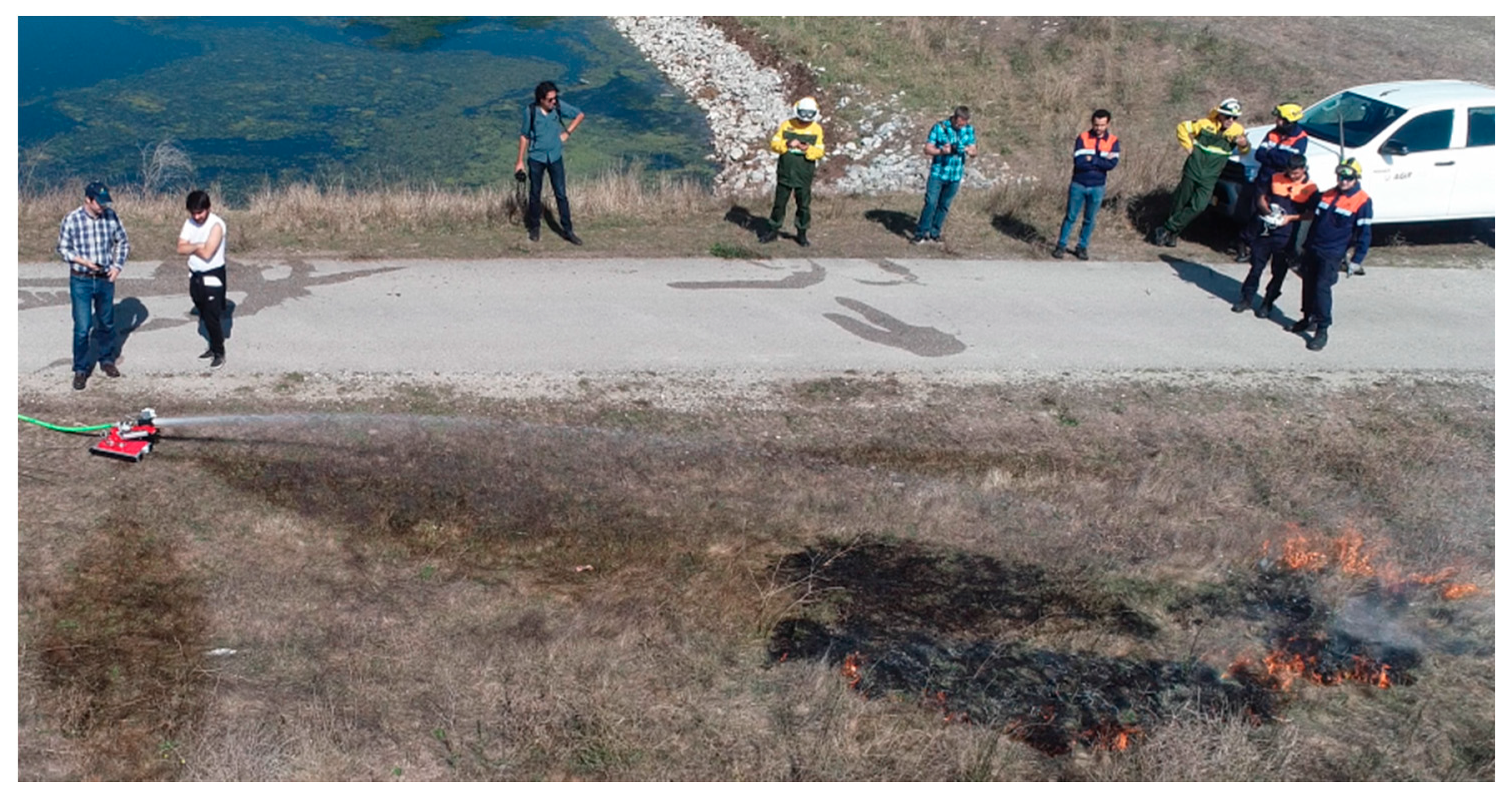
Initial field testing was made with a controlled small fire on a field with dry vegetation, which was recently cut to a height of less than 15 cm, as shown in Figure 11. This provided us with a uniform flame size and radial spread. Ignition was started at a distance of around 20 m from the prototype, and the IR sensor was able to detect and locate the fire hot spots from the instant the fire started, triggering an alarm. The pan and tilt unit, as well as the fire nozzle, were tested with a manual remote control and worked as expected, both when the jet of water was on or off. It was confirmed that it was possible to put out a small fire by remotely manually controlling the pan and tilt water turret by looking only at the IR sensor “image” and not the fire itself, proving that this could be controlled by a human operator far away from the fire front.
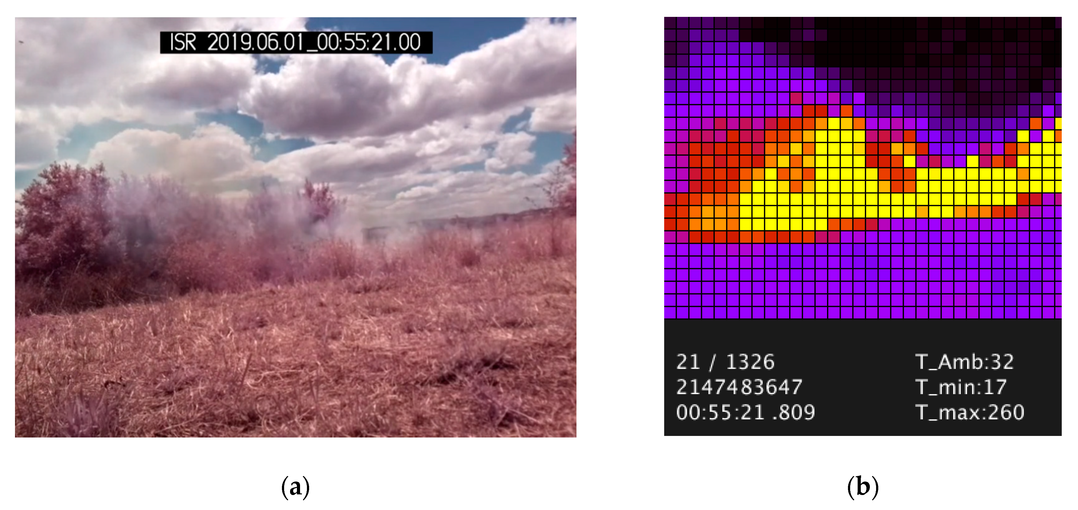
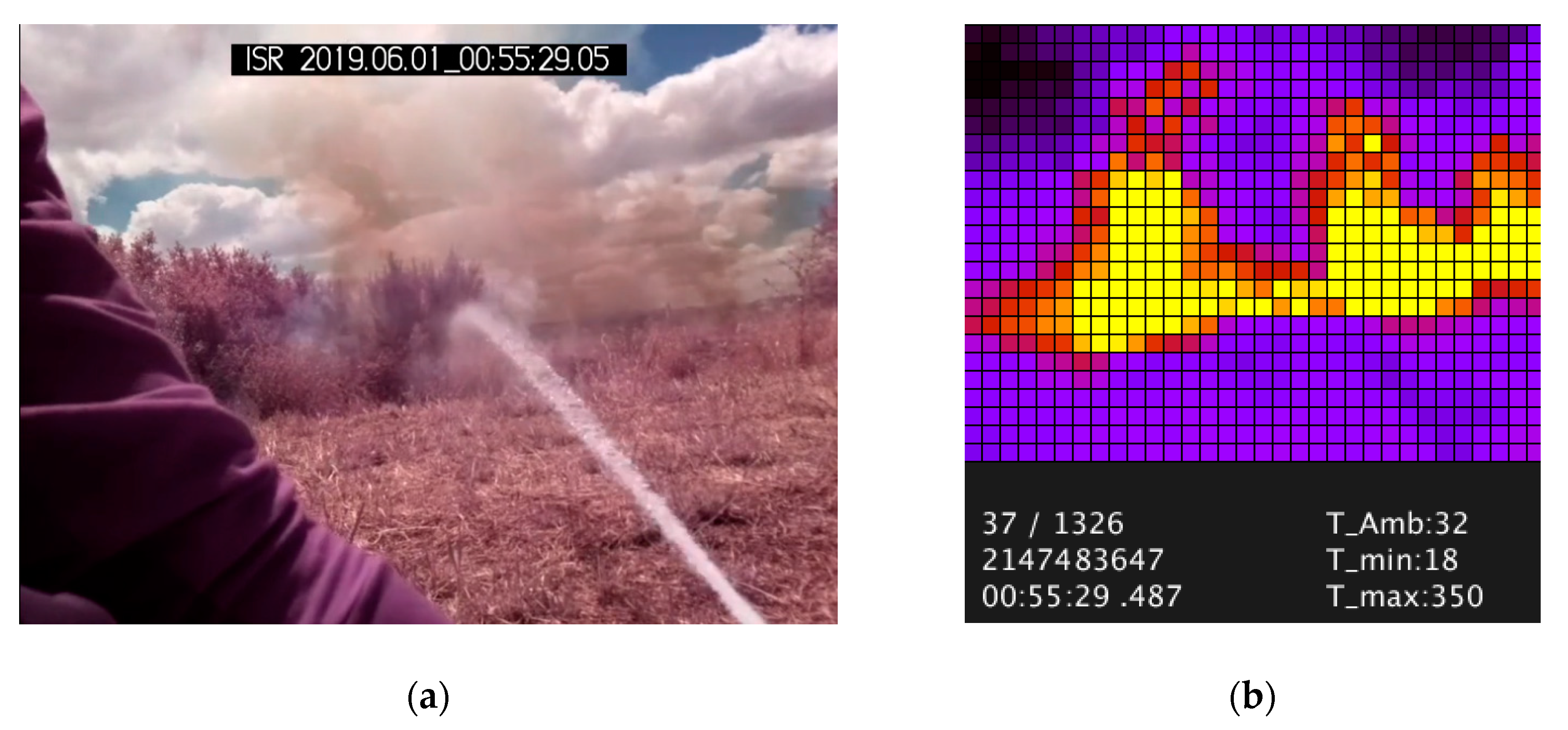
These initial tests demonstrated that the IR sensor could differentiate fire from the background and generate real-time usable data regarding fire location at several frames per second. The IR sensor could also detect an ignition behind tall and dense vegetation several seconds before smoke and flames were visible to the naked eye, proving that even at a low resolution, a low-cost IR matrix sensor is able to detect and pinpoint a small fire at close range. Figure 12a displays a photo from the point of view of the IR sensor of a small fire front behind a bush, around 15 m away. Figure 12b depicts the data collected in real time from the IR sensor. Several seconds after the ignition, the IR sensor can detect peak temperatures of 260 °C, even though to the naked eye no flames are visible, only smoke.
After activating the water jet, the attenuation of the temperature on the spot hit by water is clearly visible in Figure 13, and by adjusting the minimum and maximum thresholds of the collected data, prior to image conversion, it is somehow possible to discern the water jet from the background, indicating that if we know the temperature of the water, it might be possible to define thresholds to differentiate the water from the background and analyze its real trajectory.
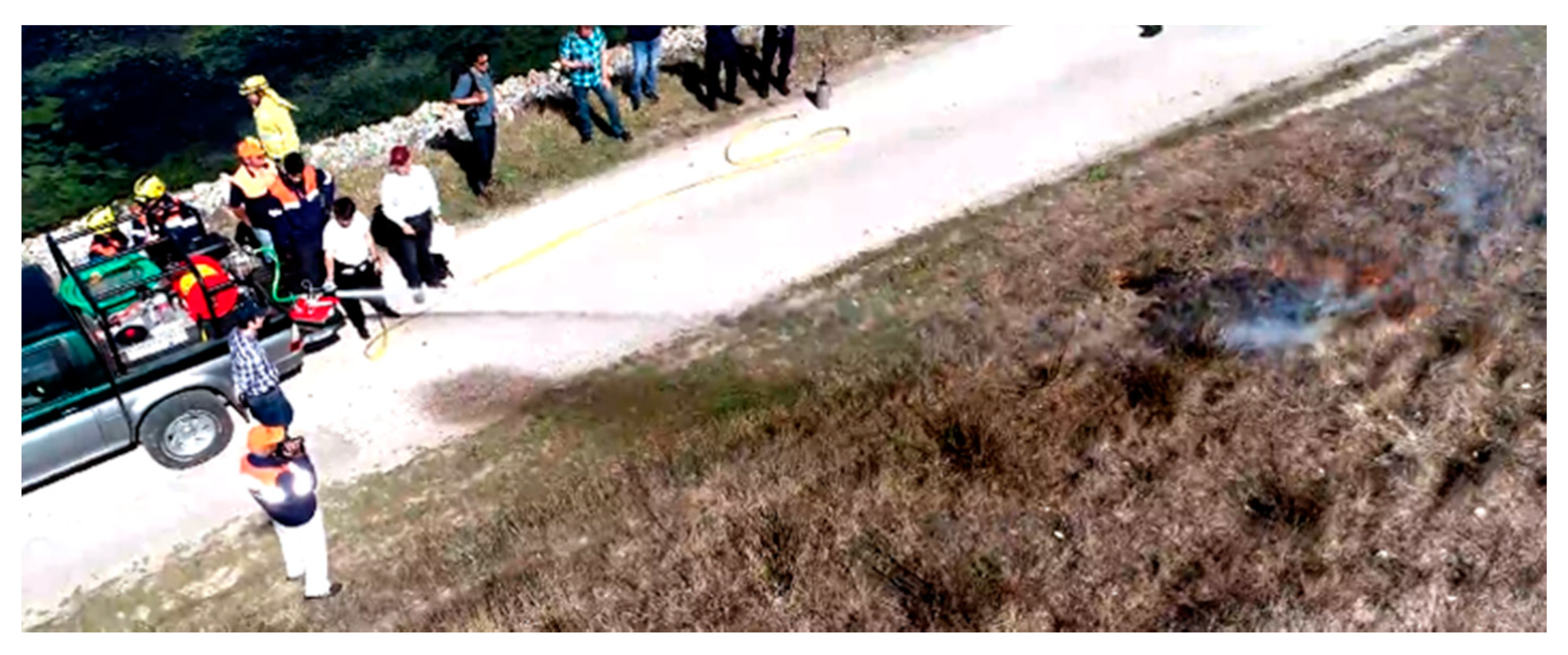
Since automated operation was the main objective of this work, a simple fire-tracking algorithm was developed. This algorithm autonomously tracked the hottest point within the field of view of the sensor, and when the temperature surpassed a threshold, e.g., 100 °C, the solenoid valve was activated and the water jet was oriented until the hottest point was at a predefined offset from the center of the matrix frame. These offsets are needed to relate the water hit point versus the IR sensor matrix. These offsets were defined, considering a fixed pressure water input and an estimated range of the jet versus the position of the hottest pixel area in the IR matrix. Field tests were performed, and the unit was installed on top of a fire rapid-response vehicle equipped with a water tank and a pump, as shown in Figure 14. This autonomous mode was partially successful, confirming an expected limitation: the offset between the actual water hit point and the hottest visible point. While this algorithm is effective at close range and high water pressure, it is prone to fail when the jet has low pressure and is aimed at a distant position, wind deflects or disperses water, or even if the terrain is not flat. We confirmed that depending on the position of the IR sensor, the parabolic water jet could obfuscate some hotspots by blocking the view of the sensor, as depicted in Figure 10.
New algorithms were developed, namely one in particular that takes into account the fact that the water jet might obfuscate the view of the IR sensor. The sensor was relocated to the underside of the nozzle, and further field testing was made at a location where the only available “fuel” was contained in 2 adjacent small cylindrical metal baskets with a capacity of 3500 cc, which were filled with dry forest vegetation and placed 14.5 m from the sensor. Two tests were made:
- Test A: Fire was started and no water jet was turned on.
- Test B: Fire was started and the water jet was launched with an inclination of 40°, pressure controlled to 2 bar, in order to fall just before hitting the baskets.
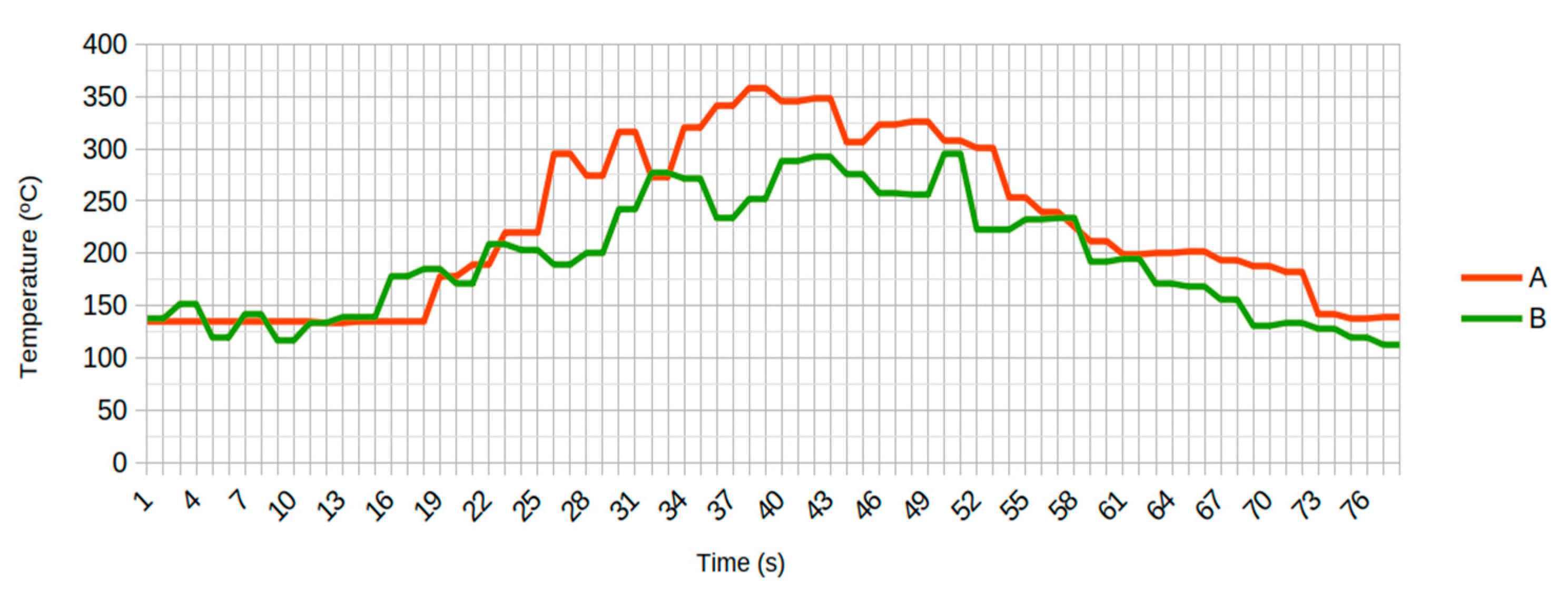
In test B, water droplets were big and disperse, falling to the ground between the 10 and 14.5 m region. Wind also led to a slight oscillation of the water jet to the left and right, altering its trajectory. Baskets were refilled with a similar amount of fuel between experiments. The initial measured baseline temperatures of over 100 °C can be explained by the fact that there were big metal objects on the background exposed to strong sun radiation. Figure 15 depicts the evolution of peak temperatures in both tests.
As can be observed in Figure 15, Tests A and B display a bell curve of the peak temperatures generated by the burn of the limited fuel. Test A is used as a reference for subsequent tests. Test B displays a similar curve to Test A, but slightly attenuated; despite the odd peaks caused by the displacement of the water jet by wind, the overall attenuation of the measured temperature can be justified by the water falling in between the sensor and the fire, effectively absorbing or dispersing some of the radiation and slightly obfuscating the fire from the sensor.
This lead to the development of a new algorithm that should methodically be able to find and eliminate fire within the range of the water jet, independently of the variations in water pressure, wind deflection, or spread of the jet. As the maximum range of the jet can be estimated by using a constant pressure of water and an elevation of 45°, it is possible to tilt the IR sensor in such a way that a known line on the array of data collected from the IR sensor in a given frame corresponds to the jet’s maximum range, hence indicating that any hot spot above this line is out of range.
Currently, in the experimental tests, the sensor is placed near the base, under the water jet, panning in solidarity with the nozzle, while maintaining a fixed tilt. When a fire spot is detected, the nozzle is panned toward the fire and tilted to 45° (providing a maximum range for the jet). When the jet is activated, if the fire spot is within reach—i.e., between the sensor and the water hit point—then, by tilting the jet down, an IR column (usually the center one) will eventually be clear of hot spots, because at some point in that column, the sensor will only “see” the water jet above and the ground below, indicating that the fire front is beyond the water hit point. By moving the jet back up and repeating the process in adjacent columns, it becomes possible to “sweep” and eliminate fire spots within the view and range of the jet. This combination of hardware and algorithm is now patent pending, and the algorithm is also under further research and development.
4. Discussion
Robotic firefighting systems are usually designed to cope with fire detection, control, and suppression, including the monitoring of hazardous conditions such as smoke, fire location, and also search and rescue. Fixed installations usually (re)act with alarms and fire sprinklers, but mobile systems can be equipped with water or foam hoses and some can even travel into unsafe areas. Several authors proposed autonomous firefighting robots [18,19,20], but the focus is mostly on mobile robot navigation and the location of fire spots, namely indoors. Some disaster relief robots, such as the “Water cannon Robot” developed by Mitsubishi Heavy Industries (MHI) [21] were designed to deal with extremely hazardous and difficult to reach locations such as fires in petrochemical plants. However, these solutions are composed of multi-robot systems, which according to the manufacturer can move autonomously, but the manufacturer does not specify if these are fully autonomous or require an operator to control the jet of water/foam. Public announcements have been made regarding military firefighting robots, such as the “Tactical Hazardous Operations Robot” (THOR) developed for the U.S. Navy, in which a humanoid robot capable of using hoses open doors and moves between unstable floors on a ship upon operator control [22]. The Thermite RS1 and RS3 [23] are other examples of robots created for the U.S. Army, using a small tank modified to include a controllable nozzle and hose; these are also remotely controlled by an operator. Finally, the “Fire Ox” [24] is another example of a remote controllable mobile robot with a built-in tank and a controllable nozzle.
Our system differs and innovates from the above solutions because it was designed to be used and mounted on a fixed location, specifically to address wildfires and with the main objective to be fully autonomous (even though manual remote operation is possible). This design was focused on the strengths and limitations of the pan and tilt motorized unit, the water jet range, the IR matrix sensor field of view, and possible disturbances such as the ones caused by wind or even a fire front out of reach, in such a way that a known ground area can be monitored and protected. This solution does not aim to halt a massive fire front or even terminate a large forest fire crossing to an urban interface. However, the system has the ability to issue early warning alarms when a fire front is near, and if in autonomous mode, it can locate the fire position and methodically attempt to suppress it. As part of the algorithm, when the fire is very close but still out of reach, the algorithm activates the jet and with a scanning motion sprays the floor with water, in order to preemptively minimize the probability of an ignition caused by a projection. If applied in a distributed manner and combined with proper terrain cleaning and distancing from trees, the system should be able to protect perimeters, mitigating the effects of fire and increasing the chance for evacuation.
5. Conclusions
This work led us to conclude that it is possible to develop innovative and low-cost mechanisms and techniques to remotely or autonomously detect and combat fires in a wide variety of environments. By combining a motorized pan and tilt water turret, an advanced sensory unit with a matrix of narrow beam far infrared (FIR) sensors, and a micro-controller, it is possible to detect and fight an approaching fire front, either in fully autonomous mode or in semi-autonomous mode in cooperation with the firemen. The developed solution also provides an opportunity for firefighters to minimize their exposition to harsh conditions such as high temperatures and heat radiation levels by avoiding manual control and handling.
If applied in a distributed manner near risky areas, such as forests, public and private infrastructures such as villages, touristic sites, and large outdoor events, which require the protection of the surrounding perimeters, then the proposed system can be used to delay the propagation of an emerging fire, mitigating its effects and increasing the chance for evacuation, avoiding the potential disasters caused by wild forest fires.
Experimental field results in a variety of natural environments validated the technical approach, indicating that when the fire is within the field of view of the FIR sensor and within the range of the water jet, such a system can provide an early fire detection alarm and autonomously mitigate an approaching fire front, minimizing the risk to human lives as well as the destruction of assets, infrastructures, forests, and wildlife, or in a worst-case scenario, increasing the chance for safe evacuation. The algorithms are also under further R&D, as they can be improved to provide optimized fire detection and autonomous firefighting techniques using several coordinated autonomous systems. Self-learning algorithms can further enhance the performance of this fire detection and control system, thus providing more comprehensive protection and optimizing the use of water.
6. Patents
International Patent Request: PCT/PT2020/050026—“Autonomous Portable Firefighting System and Respective Method of Operation”
Author Contributions
Conceptualization, A.T.d.A., A.P.C. and L.M.F.; methodology, A.P.C. and L.M.F.; software, L.M.F.; investigation, A.P.C. and L.M.F.; writing—original draft preparation, L.M.F.; writing—review and editing, A.T.d.A. and L.M.F.; visualization, L.M.F.; supervision, A.T.d.A., A.P.C.; project administration, A.T.d.A.; funding acquisition, A.T.d.A. All authors have read and agreed to the published version of the manuscript.
Funding
This research was funded by ”FIREPROTECT - Sistemas de Proteção de Pessoas e Elementos Críticos Expostos a Incêndios Florestais”, grant number Centro-01-0246-FEDER-000015
Acknowledgments
UID/EEA/00048/2020, financed by FCT—Fundação para a Ciência e a Tecnologia, Ministério da Ciência, Tecnologia e Ensino Superior; ADAI; Miguel Antunes and Carlos Viegas.
Conflicts of Interest
The authors declare no conflict of interest.
References
- T&D World Library. Wildfire Risk Mitigation for Electric Utilities. 2020. Available online: https://www.tdworld.com/wildfire/whitepaper/21125390/wildfire-risk-mitigation (accessed on 18 June 2020).
- FAO. Technical guide for the countries of the Mediterranean basin. In International Handbook on Forest Fire Protection; Département Gestion des territoires, Division Agriculture et Forêt Méditerranéennes, Groupement d’Aix en Provence: d’Aix en Provence, France, 2000; Available online: http://www.fao.org/forestry/27221-06293a5348df37bc8b14e24472df64810.pdf (accessed on 18 June 2020).
- Departamento de Gestão de Áreas Públicas e de Proteção Florestal. 10.o Relatório Provisório de Incêndios Florestais—2017; Tech. Rep.; Instituto da Conservação da Natureza e Florestas: Lisboa, Portugal, 2017; Available online: http://www2.icnf.pt/portal/florestas/dfci/Resource/doc/rel/2017/10-rel-prov-1jan-31out-2017.pdf (accessed on 18 June 2020).
- State of California. Incident Information—Numbers of Fires and Acres. Available online: http://cdfdata.fire.ca.gov/incidents/incidents_stats (accessed on 18 June 2020).
- San-Miguel-Ayanz, J.; Costa, H.; de Rigo, D.; Libertà, G.; Artes, T.; Durrant, T.; Nuijten, D.; Loffler, P.; Moore, P.; Baetens, J.; et al. Basic Criteria to Assess Wildfire Risk at the Pan-European Level. 2018. Available online: https://publications.jrc.ec.europa.eu/repository/bitstream/JRC113923/jrc_tech_rep_basic_criteria_for_wildfire_risk_assessment_2018_onlinefinal_pdf.pdf (accessed on 18 June 2020). [CrossRef]
- Emergency Response Coordination Centre (ERCC)—DG ECHO. Daily Map|04/11/2019. Europe|Forest Fires January–October 2019. Available online: https://erccportal.jrc.ec.europa.eu/ercmaps/ECDM_20191104_Forestfires_Europe.pdf (accessed on 18 June 2020).
- CAMEO Chemicals. Formaldehyde, Solution, Flammable. Available online: https://cameochemicals.noaa.gov/chemical/769 (accessed on 18 June 2020).
- How Fire Works. Available online: https://science.howstuffworks.com/environmental/earth/geophysics/fire1.htm (accessed on 18 June 2020).
- The Combustion Reaction. Available online: http://www.whatischemistry.unina.it/en/burn.html (accessed on 18 June 2020).
- National Fire Danger Rating System. Available online: https://www.nps.gov/articles/understanding-fire-danger.htm (accessed on 18 June 2020).
- Singh, T.; Bonne, U. Gas sensors. In Reference Module in Materials Science and Materials Engineering; Elsevier: Amsterdam, The Netherlands, 2017; ISBN 9780128035818. [Google Scholar] [CrossRef]
- Li, P.; Zhao, W. Image fire detection algorithms based on convolutional neural networks. Case Stud. Therm. Eng. 2020, 19, 100625. [Google Scholar] [CrossRef]
- Huang, X.; Du, L. Fire detection and recognition optimization based on virtual reality video image. IEEE Access 2020, 8, 77951–77961. [Google Scholar] [CrossRef]
- How UV, IR and Imaging Detectors Work. Available online: https://www.azosensors.com/article.aspx?ArticleID=815 (accessed on 18 June 2020).
- Liu, Y.; Liu, Y.; Xu, H.; Teo, K. Forest fire monitoring, detection and decision making systems by wireless sensor network. In Proceedings of the 2018 Chinese Control and Decision Conference (CCDC), Shenyang, China, 9–11 June 2018; pp. 5482–5486. [Google Scholar] [CrossRef]
- Owayjan, M.; Freiha, G.; Achkar, R.; Abdo, E.; Mallah, S. Firoxio: Forest fire detection and alerting system. In Proceedings of the MELECON 2014—2014 17th IEEE Mediterranean Electrotechnical Conference, Beirut, Lebanon, 13–16 April 2014; pp. 177–181. [Google Scholar] [CrossRef]
- Singh, P.; Sharma, A. An insight to forest fire detection techniques using wireless sensor networks. In Proceedings of the 2017 4th International Conference on Signal Processing, Computing and Control (ISPCC), Solan, India, 21–23 September 2017; pp. 647–653. [Google Scholar] [CrossRef]
- Hassanein, A.; Elhawary, M.; Jaber, N.; El-Abd, M. An autonomous firefighting robot. In Proceedings of the 2015 International Conference on Advanced Robotics (ICAR), Istanbul, Turkey, 27–31 July 2015; pp. 530–535. [Google Scholar] [CrossRef]
- Diwanji, M.; Hisvankar, S.; Khandelwal, C. Autonomous fire detecting and extinguishing robot. In Proceedings of the 2019 2nd International Conference on Intelligent Communication and Computational Techniques (ICCT), Jaipur, India, 28–29 September 2019; pp. 327–329. [Google Scholar] [CrossRef]
- Khoon, T.N.; Sebastian, P.; Saman, A.B.S. Autonomous fire fighting mobile platform. Procedia Eng. 2012, 41, 1145–1153. [Google Scholar] [CrossRef]
- Mitsubishi Heavy Industries Develops Autonomous “Water Cannon Robot” and “Hose Extension Robot” for Use in Firefighting. Available online: https://www.mhi.com/news/story/190325.html (accessed on 5 August 2020).
- Tactical Hazardous Operations Robot. Available online: https://www.military.com/video/forces/technologies/tactical-hazardous-operations-robot/2969584431001 (accessed on 5 August 2020).
- THERMITE™ RS1 AND RS3. Available online: http://www.roboticfirefighters.com/ (accessed on 5 August 2020).
- New Fire Ox Can Do What Humans Can’t. Available online: https://www.fireproductsearch.com/new-fire-ox-can-humans-cant/ (accessed on 5 August 2020).
Figure 1.
Average number of fires mapped in the European Forest Fire Information System (EFFIS), classified in 4 categories, for the period 2000–2017 [5].
Figure 1.
Average number of fires mapped in the European Forest Fire Information System (EFFIS), classified in 4 categories, for the period 2000–2017 [5].

Figure 2.
Burnt forest areas in Europe (ha), in the period 2008 to 2019 Emergency Response Coordination Centre (ERCC)—Directorate-General for European Civil Protection and Humanitarian Aid Operations (DG ECHO) Daily Map | 04/11/2019 [6].
Figure 2.
Burnt forest areas in Europe (ha), in the period 2008 to 2019 Emergency Response Coordination Centre (ERCC)—Directorate-General for European Civil Protection and Humanitarian Aid Operations (DG ECHO) Daily Map | 04/11/2019 [6].

Figure 3.
Hydrocarbon fuel burn spectrum, covering UV, visible, and IR up to 6 µm. Peaks associated with CO2 and H2O are visible at around 2.9 µm and 4.3 µm and can be used as a hydrocarbon fuel burn signature [14] (Image Copyright Simtronics 2015. Source: https://www.azosensors.com/article.aspx?ArticleID=815).

Figure 4.
Infrared sensor field-of-view and sensibility versus distance [14] (Image Copyright Azosensors 2017. Source: https://www.azosensors.com/article.aspx?ArticleID=815).
Figure 4.
Infrared sensor field-of-view and sensibility versus distance [14] (Image Copyright Azosensors 2017. Source: https://www.azosensors.com/article.aspx?ArticleID=815).

Figure 5.
Motorized firefighter monitor/nozzle simplified block diagram.

Figure 6.
Far infrared (FIR) sensor block diagram (Image Copyright Melexis. Source: https://www.melexis.com/en/products/sense/temperature-sensors).
Figure 6.
Far infrared (FIR) sensor block diagram (Image Copyright Melexis. Source: https://www.melexis.com/en/products/sense/temperature-sensors).

Figure 7.
Pan and tilt unit with electro-valve, nozzle, and sensor brackets.

Figure 8.
Simulated parabola for a water jet, with a launch angle of 10° and a launch speed of 40 m/s.
Figure 8.
Simulated parabola for a water jet, with a launch angle of 10° and a launch speed of 40 m/s.

Figure 9.
Simulated IR sensor point of view, when mounted at a distance of 12 cm from the center of the nozzle, at the following locations: (a) under; (b) above; (c) to the left; (d) to the right.
Figure 9.
Simulated IR sensor point of view, when mounted at a distance of 12 cm from the center of the nozzle, at the following locations: (a) under; (b) above; (c) to the left; (d) to the right.

Figure 10.
Simulated jet parabola and IR sensor projection matrix in perspective.

Figure 11.
Initial experiments on the field with the pan and tilt nozzle unit directing the water jet to the fire area, based on the fire sensor information.
Figure 11.
Initial experiments on the field with the pan and tilt nozzle unit directing the water jet to the fire area, based on the fire sensor information.

Figure 12.
(a) Photo (without IR filter) from the point of view of the IR sensor, with fire hidden behind vegetation, just before activating the water jet; (b) Sensor output data after processing.
Figure 12.
(a) Photo (without IR filter) from the point of view of the IR sensor, with fire hidden behind vegetation, just before activating the water jet; (b) Sensor output data after processing.

Figure 13.
(a) Photo (without IR filter) from the point of view of the IR sensor, with fire hidden behind vegetation, immediately after activating the water jet; (b) IR sensor data after processing.
Figure 13.
(a) Photo (without IR filter) from the point of view of the IR sensor, with fire hidden behind vegetation, immediately after activating the water jet; (b) IR sensor data after processing.

Figure 14.
Demonstration of sensor-based autonomous firefighting test.

Figure 15.
Sensor obfuscation test—Peak temperatures vs. time. Test A: Fire was started, no water jet was turned on; Test B: Fire was started and the water jet had a launch elevation of 40°, pressure controlled to 2 bar, in order to fall just before hitting the baskets.
Figure 15.
Sensor obfuscation test—Peak temperatures vs. time. Test A: Fire was started, no water jet was turned on; Test B: Fire was started and the water jet had a launch elevation of 40°, pressure controlled to 2 bar, in order to fall just before hitting the baskets.


Table 1.
Sensor vs. pixel field of view (FoV) per plane.
| Plane | Pixel Count | Total FoV | Pixel FoV |
|---|---|---|---|
| H | 32 | 55° | 1.72° |
| V | 24 | 35° | 1.46° |
Table 2.
Area width and height covered by the sensor as a function of distance.
| Covered Width/Height | Distance (m) | |||||||||
|---|---|---|---|---|---|---|---|---|---|---|
| 1 | 2 | 3 | 4 | 5 | 6 | 7 | 8 | 9 | 10 | |
| Sensor covered width (m) | 1.0 | 2.1 | 3.1 | 4.2 | 5.2 | 6.3 | 7.3 | 8.3 | 9.4 | 10.4 |
| Pixel covered width (cm) | 3.3 | 6.5 | 9.8 | 13.0 | 16.3 | 19.5 | 22.8 | 26.0 | 29.3 | 32.5 |
| Sensor covered height (m) | 0.6 | 1.3 | 1.9 | 2.5 | 3.2 | 3.8 | 4.4 | 5.0 | 5.7 | 6.3 |
| Pixel covered height (cm) | 2.6 | 5.3 | 7.9 | 10.5 | 13.1 | 15.8 | 18.4 | 21.0 | 23.7 | 26.3 |
© 2020 by the authors. Licensee MDPI, Basel, Switzerland. This article is an open access article distributed under the terms and conditions of the Creative Commons Attribution (CC BY) license (http://creativecommons.org/licenses/by/4.0/).
Share and Cite
MDPI and ACS Style
Ferreira, L.M.; Coimbra, A.P.; de Almeida, A.T. Autonomous System for Wildfire and Forest Fire Early Detection and Control. Inventions 2020, 5, 41. https://0-doi-org.brum.beds.ac.uk/10.3390/inventions5030041
AMA Style
Ferreira LM, Coimbra AP, de Almeida AT. Autonomous System for Wildfire and Forest Fire Early Detection and Control. Inventions. 2020; 5(3):41. https://0-doi-org.brum.beds.ac.uk/10.3390/inventions5030041
Chicago/Turabian StyleFerreira, Luís Miguel, A. Paulo Coimbra, and Aníbal T. de Almeida. 2020. "Autonomous System for Wildfire and Forest Fire Early Detection and Control" Inventions 5, no. 3: 41. https://0-doi-org.brum.beds.ac.uk/10.3390/inventions5030041