
Autonomous Underwater Robot Fuzzy Motion Control System with Parametric Uncertainties


1
Department of Cyber-Physical Systems, St. Petersburg State Marine Technical University, 190121 Saint-Petersburg, Russia
2
Department of Ship’s Electrical Equipment and Automatization, Kerch State Maritime Technological University, 298309 Kerch, Russia
3
Department of Complex Information Security, Admiral Makarov State University of Maritime and Inland Shipping, 198035 Saint-Petersburg, Russia
4
Graduate School of Cyber-Physical Systems and Control, Peter the Great St. Petersburg Polytechnic University, 194064 Saint-Petersburg, Russia
*
Author to whom correspondence should be addressed.
Designs 2021, 5(1), 24; https://0-doi-org.brum.beds.ac.uk/10.3390/designs5010024
Submission received: 17 January 2021
/
Revised: 14 March 2021
/
Accepted: 19 March 2021
/
Published: 23 March 2021
(This article belongs to the Section Mechanical Engineering Design)
Abstract
:The paper describes the design of a fuzzy motion control system of an autonomous underwater vehicle. A mathematical model of the underwater vehicle is synthesized. A fuzzy regulator for controlling the depth of immersion autonomous underwater vehicle is designed. The quality of control for step control, harmonic control, as well as various types of exogenous disturbances, is investigated. The comparison of the functioning quality of the designed fuzzy controller with the proportional–derivative controller is made. It is shown that the designed fuzzy controller provides a higher quality of control compared to the proportional–derivative controller. The proposed fuzzy controller provides high-quality control of the plant under uncertainties.
1. Introduction
Underwater robotics objects operate in difficult conditions of underwater navigation. Modern automatic movement control systems of autonomous underwater vehicles (AUV) should provide increased accuracy of AUV’s controlled movement along a given path, achieving maximum speed, optimal control in complex hydrometeorological conditions, under the influence of various kinds of disturbances.
In addition, the peculiarity of working underwater is the presence of external and internal (parametric) disturbances. These disturbances have a significant impact on the operation of robotic objects underwater and on the robot’s performance of its tasks. Therefore, the development and application of new approaches to the synthesis of automatic control systems for underwater objects are required. These perturbations are difficult, and in most cases impossible to measure, so the AUV motion control process takes place under conditions of uncertainty [1,2,3,4,5,6].
The control of underactuated underwater vehicles is an important and urgent task, which can be seen from numerous reviews and articles devoted to this problem. For instance [7,8,9,10]. A review of the scientific and technical literature on control systems shows that the main direction of further development of the theory of synthesis of automatic control systems for autonomous underwater robots in the conditions of uncertainty of their parameters and environmental characteristics is the use of artificial intelligence elements—fuzzy regulators [3,7,10].
A feature of our work is the consideration of the problem of control of a partially controlled submerged body. In fact, the depth rate of it can only be adjusted by changing its buoyancy and the angle of attack of its wings, which greatly complicates the problem. Moreover, the body under study functions under conditions of parametric uncertainties, which, as will be shown below, requires the use of an adaptive controller.
2. Description of the Problem
When solving the problems of navigation, orientation, and motion control of underwater robots and vehicles, various coordinate systems are used [6]. This is due to the difference in tasks, as well as the fact that the structure and form of the equations substantially depend on the choice of coordinate system.
The choice of coordinate systems is predetermined by the method known in mechanics of dividing the complex motion of a body into translational with some point taken as a pole, rotational (spherical) relative to this pole.
AUV motion analysis will be carried out in a coordinate system stationary relative to the Earth whose origin at the initial moment of time coincides with the center of mass of the robot. The coordinate system x-y, rigidly connected with the robot, is chosen as follows. The origin is placed in the center of mass, the y axis is located in the diametrical plane and directed towards the nose of the robot so that, in its natural position, the axis coincides with the horizon (the y axis is the longitudinal axis of the robot). The x axis should coincide with the line of intersection of the main planes of the robot and have a direction up from the center of displacement.
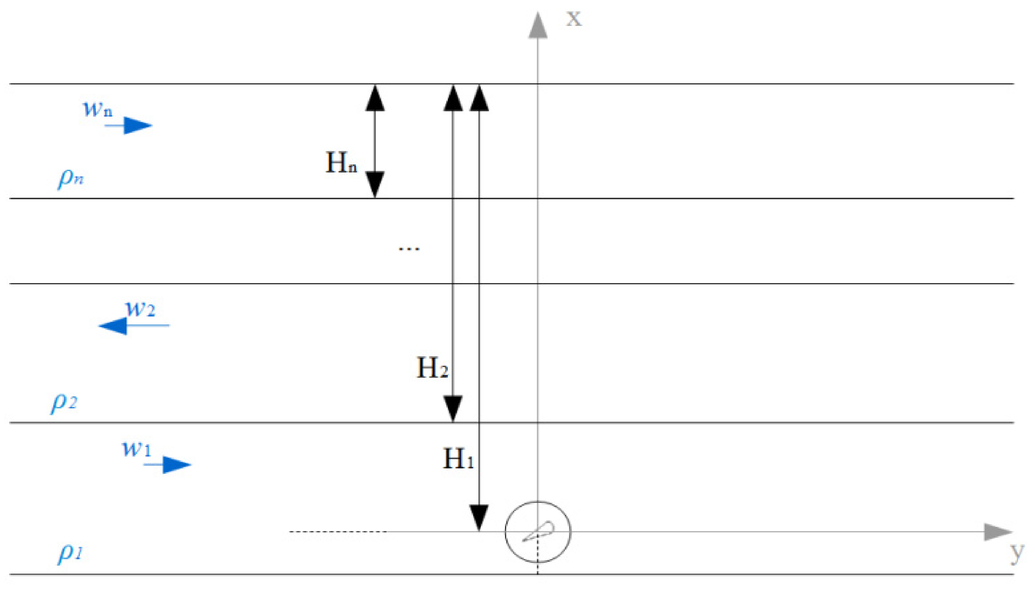
Next, we consider the movement of an underwater vehicle in an unlimited reservoir of finite depth, filled with an ideal incompressible non-heat-conducting stratified fluid with a viscosity effect. Viscosity is taken into account in the sense of the presence of the Stokes drag force. It is assumed that each layer has its own density, which is considered to be known in advance.
AUV performs plane-parallel movement. At the initial time, the apparatus rests at a given depth. Each given layer of the medium in which the apparatus moves has a constant density. Layer densities may vary. Layers can exhibit rectilinear uniform motion along the x axis. At this stage, we assume that the velocities and directions of motion of the layers are given (see Figure 1).
The solution can be obtained as the sum of the solutions at intervals corresponding to the layers of the medium. That is, first of all, the problem for one layer should be solved.
3. Mathematical Model
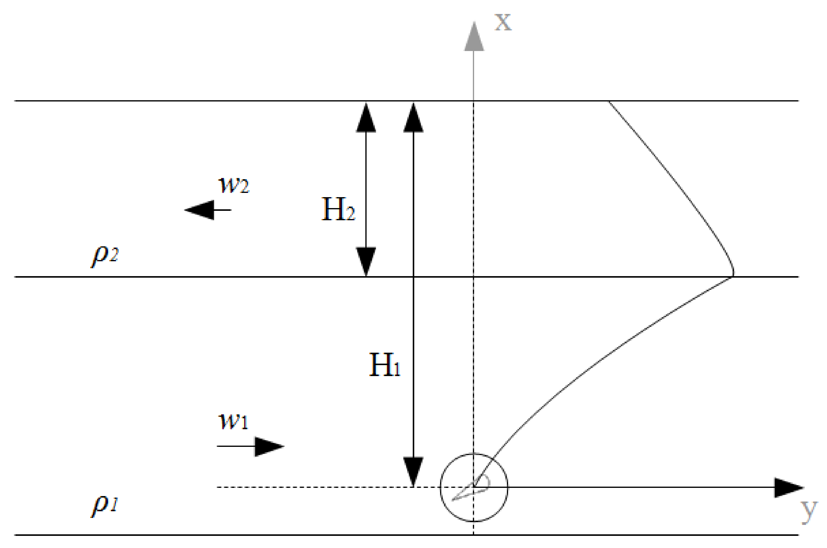
The underwater vehicle under consideration is a spherical body. The body has two wings of finite wingspan. The trajectory of the object is the trajectory of the center of the ball.
As an example, we consider the case for a medium including two layers with different parameters as shown in Figure 2. The upper layer of water has a thickness of H2. In this layer, a sea current is observed with a speed of w2. The density of water in this layer is taken equal to .
In the second layer (Figure 2), a sea current is observed at a speed of w1. The density of water in this layer is taken to be equal to . The initial submersion depth of the underwater vehicle is H1.
The following forces act on the underwater vehicle (see Figure 3): —buoyant or Archimedean force; —gravity; the total drag force [4]
where, —drag coefficient for a body of a given shape, —fluid density, —characteristic area of the streamlined body, —body speed, for ball and for planes (wings); lifting force
force of inductive resistance
where, S is the wing surface area, is the angle of attack and is initial angle of attack, k—wing aspect ratio and —viscosity.
The equations of motion of an autonomous underwater vehicle in projections on the and axis can be represented as follows:
where m is the mass of the object.
Let us make an assumption about a small angle of attack. This assumption ensures the smallness of , therefore, we have , .
After replacing the variables:
We get a system of differential equations of the first order [4]:
where , , , , , , V is the volume of the body, Skp is the square of the wings’ surface, c0_spsh is the coefficient of the body’s form, Sw is the square of the body’s surface and c0_w is the coefficient of added mass of the water.
The movement of the apparatus to follow a given trajectory is controlled by changing the angle of attack .
A numerical solution for Model (6) can be obtained using the fourth-order Runge–Kutta method, for example.
4. Synthesis of a Fuzzy Controller to Stabilize the Depth of an Underwater Robot
Based on a comparison of methods for constructing a fuzzy controller [2] we formulate a method for the synthesis of the AUV depth stabilization controller.
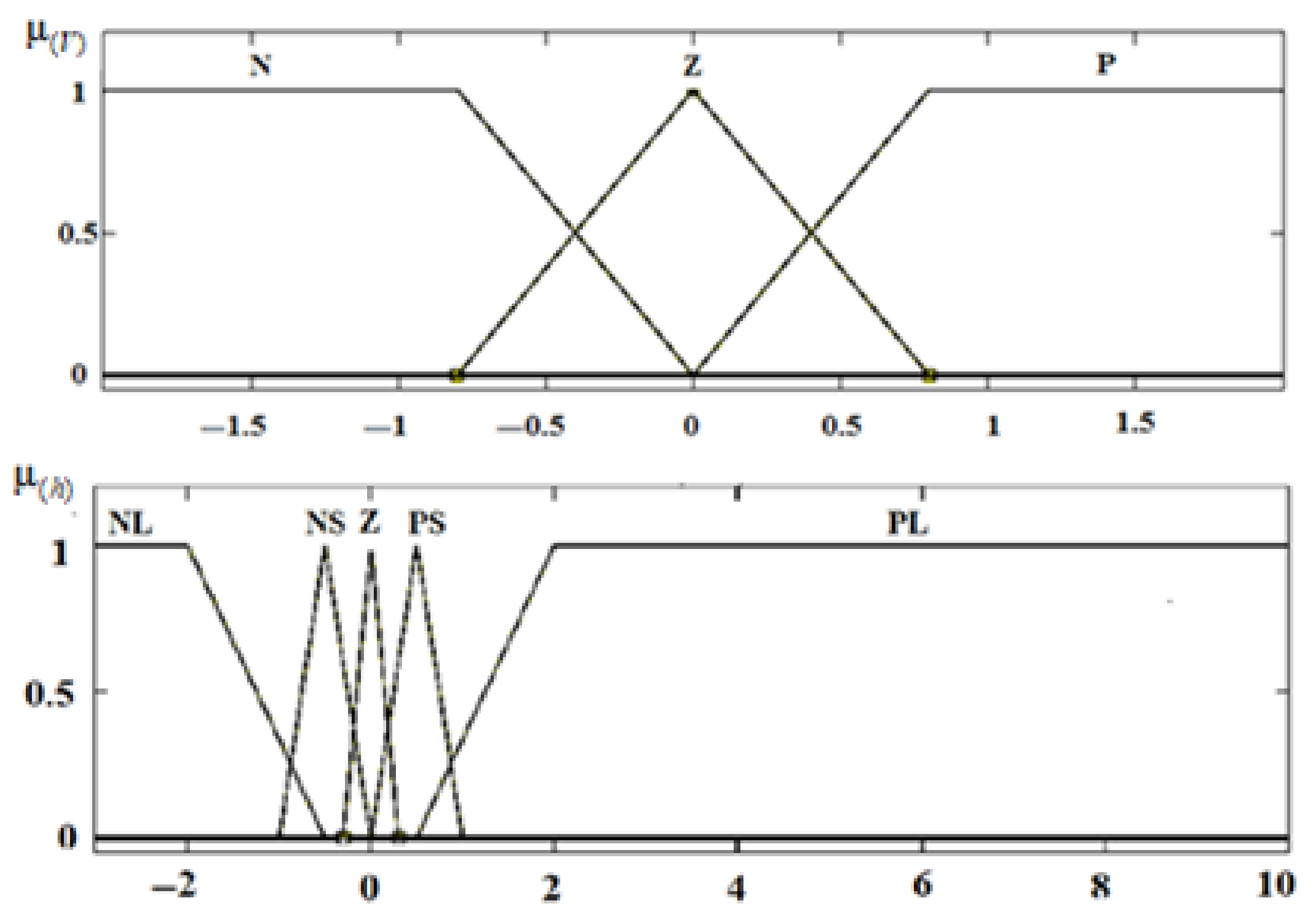
Linguistic variables are qualitatively characterized by term sets, chosen as follows: negative large (NL), negative small (NS) zero (Z), positive small (PS), positive large (PL), which are described on the universal set, membership functions depth and linear vertical velocity. To describe the input variable V, we divide the range of its values into three subsets: negative (N), zero (Z), positive (P).
The output linguistic variable T is the traction force in the vertical direction. It has the following terms: negative strong (NL), negative average (N), negative small (NS), zero (Z), positive small (PS), positive average (P), positive strong (PL). Membership function options are shown in Figure 4.
After determining the number of terms of each linguistic variable and the distribution of membership functions, fuzzy rules are formed. These rules are created based on the experience of an expert who expresses, in a formal language, possible combinations of control variables [11]. For fuzzy inference, a fuzzy model of the Sugeno type is used, where each rule is of the following type: IF “h is x” AND “V is y”, THEN “T is z”. Here x, y are the subsets of input variables, z is the subset of the output variable.
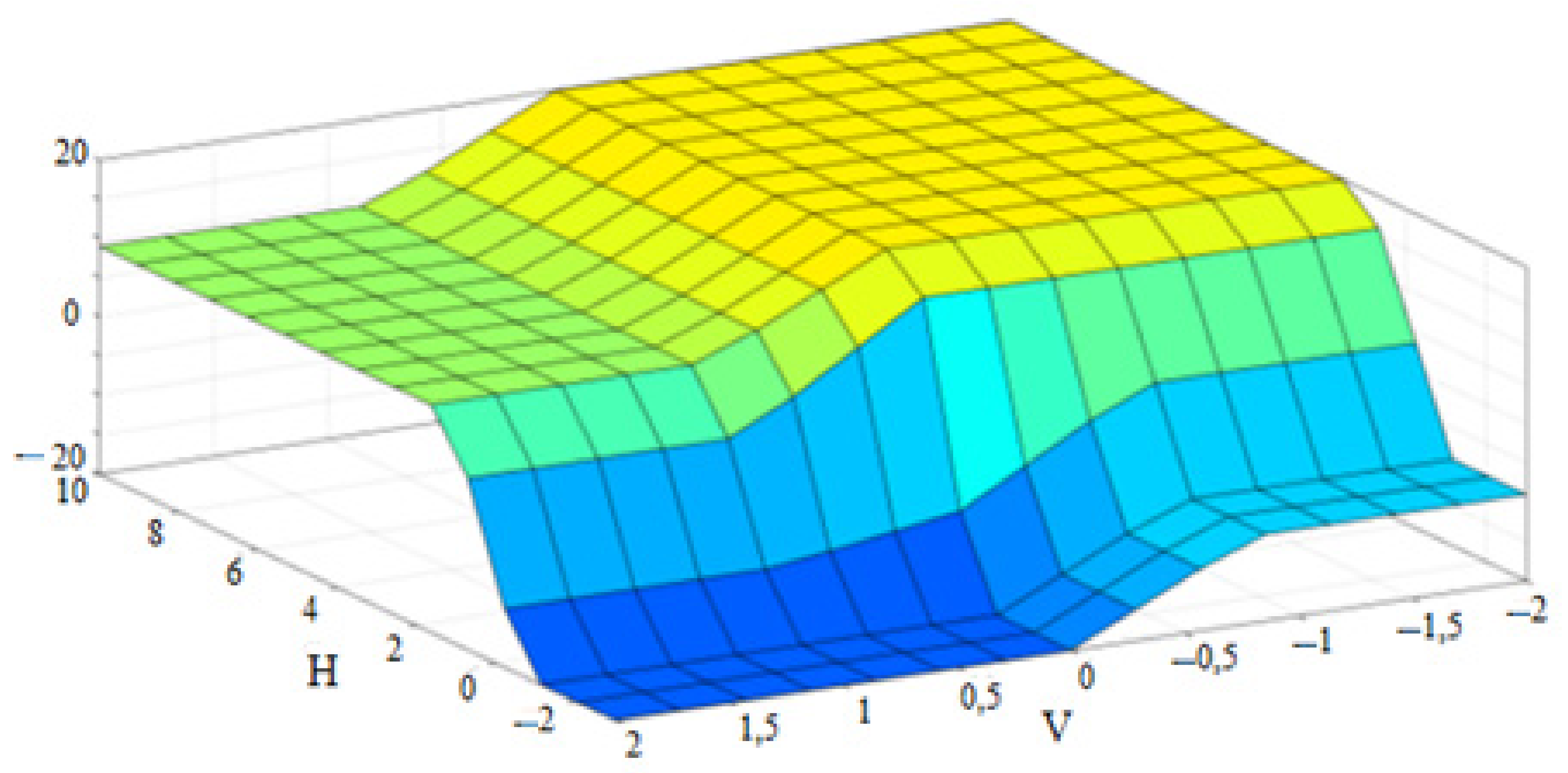
Using the Fuzzy Logic Toolbox application package in the MATLAB interactive system, a fuzzy inference surface is obtained that displays the operation of the controller (Figure 5).
A simulation of an underwater robot in a MATLAB environment was created using typical blocks of the Simulink package (Figure 6). Although during the simulation all the necessary data on the system parameters can be obtained directly from the developed model, the proposed control system is focused on practical application in a real device too. In this regard, an observer was introduced into the scheme (Figure 6), which estimates the rate of depth change and the value of the depth itself. This will make it possible to further investigate for the model the features of the system introduced by the observer, its error, etc., and finally its contribution to the parametric uncertainty systems.
5. Simulation Results
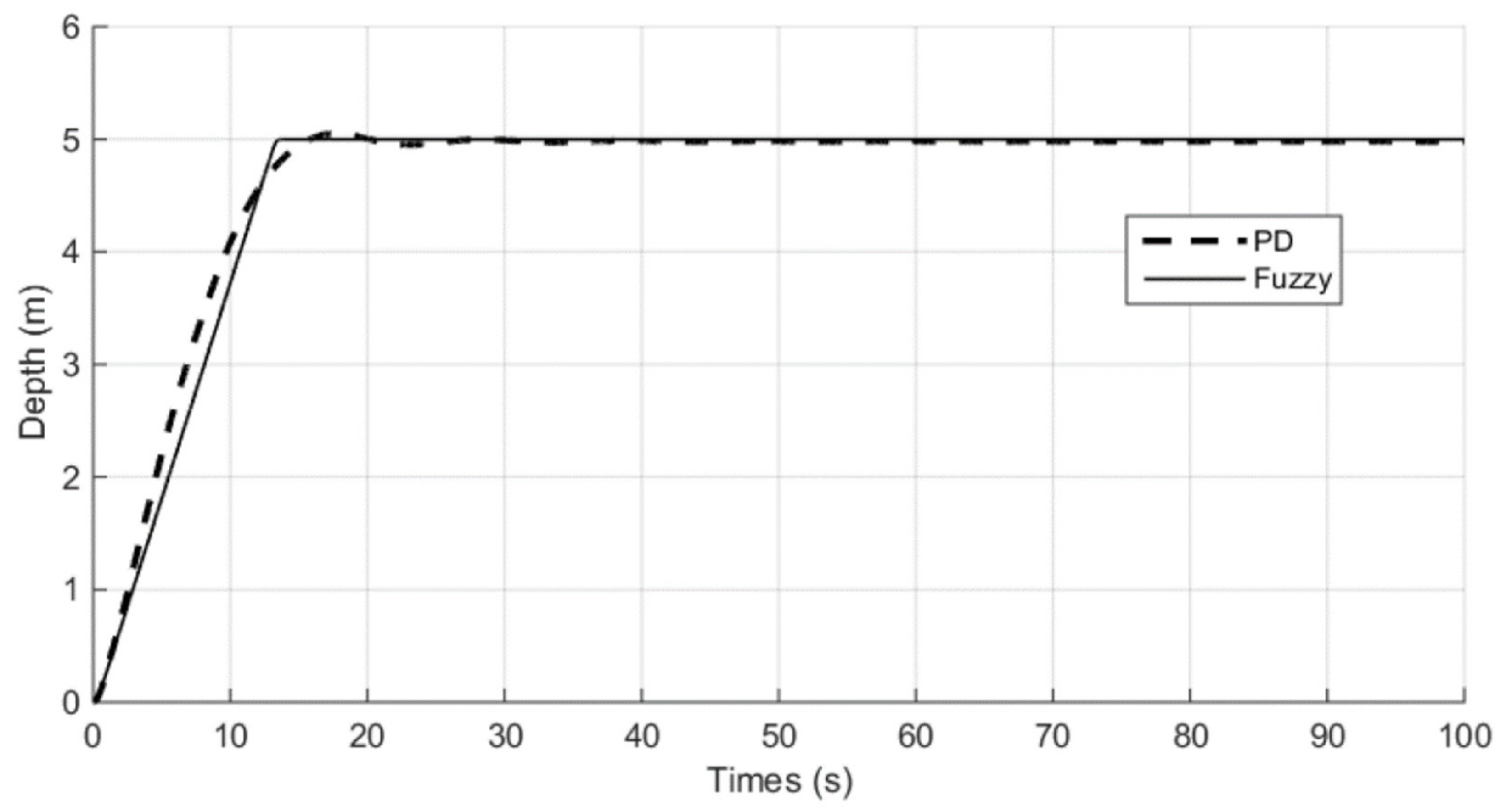
The fuzzy control system was simulated using the MATLAB package. Figure 7 shows a test model that includes the plant and the actual fuzzy controller, as well as an observer. Figure 8 and Figure 9 show graphs of the dependence of depth on time when controlling the proportional–derivative (PD) controller and when controlling a fuzzy controller.
As can be seen from Figure 7, a fuzzy regulator improves the accuracy and speed of reaching a given depth. At the same time, as also can be seen from Figure 7, overshoot is reduced. Since the type of underwater object under study is underactuated or partially controlled, the most important benefit that can be seen in this graph is an almost sixfold reduction in the time at which depth control takes place. It is not even the entrance to the five percent zone that is important here, but the end of the depth control during which the limited energy of the apparatus is expended. The fuzzy controller finishes adjusting after 12 s from the start of the depth change process, while the PD controller continues adjusting depth for more than 60 s.
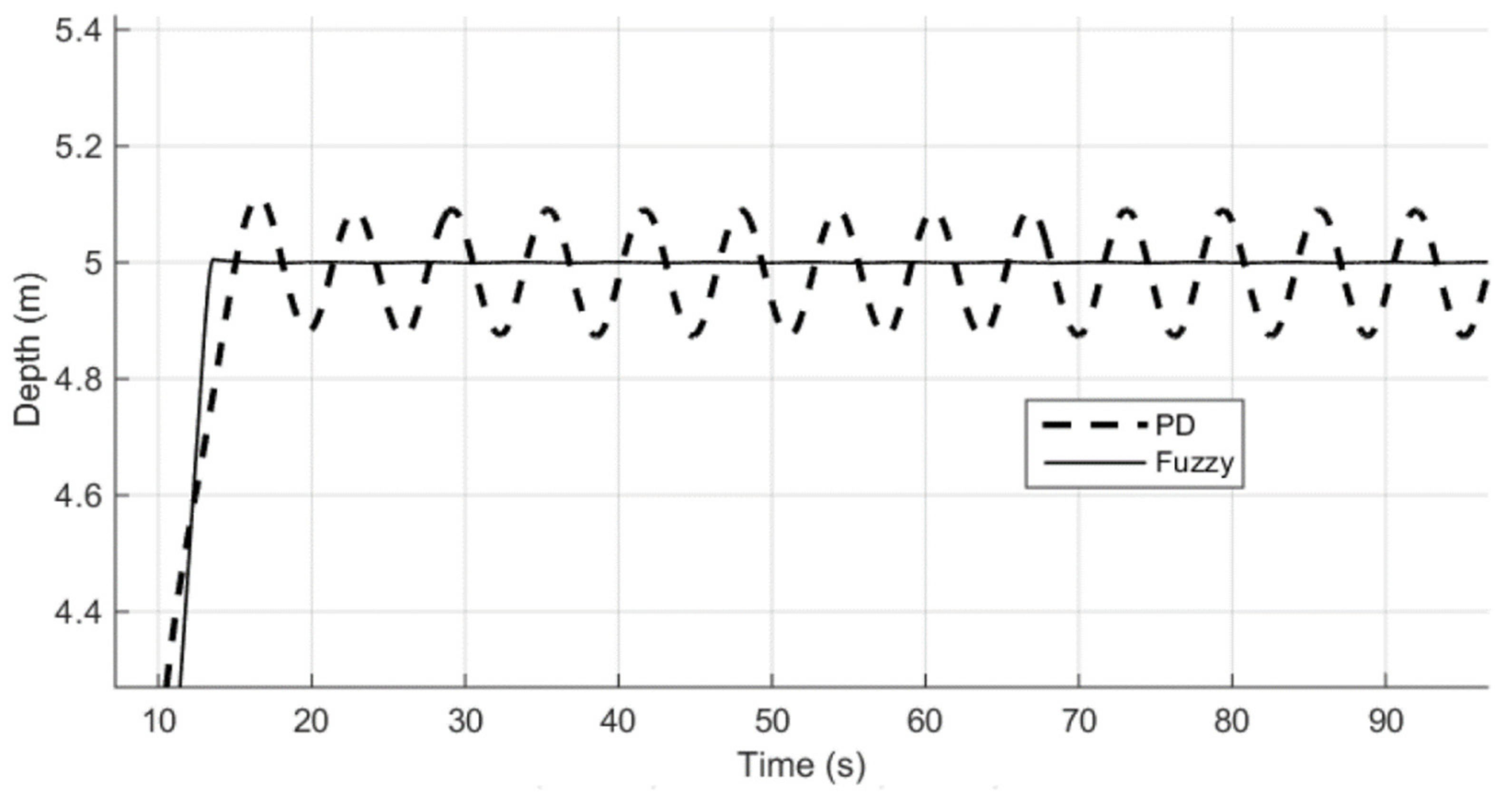
Since the subject of the study is a system with parametric uncertainties, the question of how external destabilizing disturbances or exogenous factors influence the quality of the proposed regulator’s performance becomes equally important. Figure 8 shows a very important result. A comparison of the operation of a PD controller and a fuzzy controller under conditions of a harmonic external disturbance is presented. As it can be seen (Figure 8), if in the previous case (Figure 7), the time of regulation with a PD controller could be reduced by introducing a threshold limiter, then this approach does not work here (Figure 8) anymore. Indeed, the PD regulator leads to significant fluctuations in depth in the presence of external disturbances in the system, while the fuzzy regulator ensures the maintenance of a given depth. This is due to the adaptive features of the fuzzy controller used.
The use of fuzzy logic methods for the synthesis of control laws of modern automatic control systems, consisting of a set of various underwater robots, can increase the reliability of the operation of underwater hydraulic structures in difficult or extreme conditions due to periodic monitoring of their condition.
6. The Study of the Efficiency of the Fuzzy Control System with a Stepwise Change in the Depth of Immersion AUV
The simulation showed the effective use of a fuzzy controller (FC) of the proposed structure for stabilization at depth. We will now establish the possibilities for the effective operation of the FC for operating cases when the new value of the given depth is such that the AUV does not have time to develop the maximum vertical speed.
It is obvious that
where, —the path of acceleration, steady motion, and braking of AUV, respectively.
Then the minimum value of the change in the depth of AUV, at which the considered FC’s work efficiently, is defined as the sum
For a specific AUV with known values of mass, hydrodynamic drag coefficient, and characteristics of a moving device, the value .
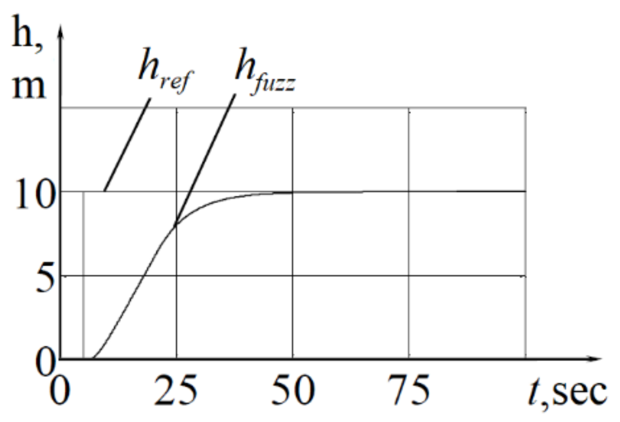
For , applying the FC with the dependencies synthesized above for the coefficients k1 and k2 is ineffective. For example, let the new value of the given depth m. Figure 8 shows the operation of the FC, the coefficients k1 and k2 of which correspond to a depth of 10 m, and in Figure 9 the operation of the FC with the coefficients k1 = 1.01 and k2 = 12, specially tuned to change the depth by 1 m, is shown.
7. Study of the Efficiency of Fuzzy Control Systems with a Harmonic Control Law
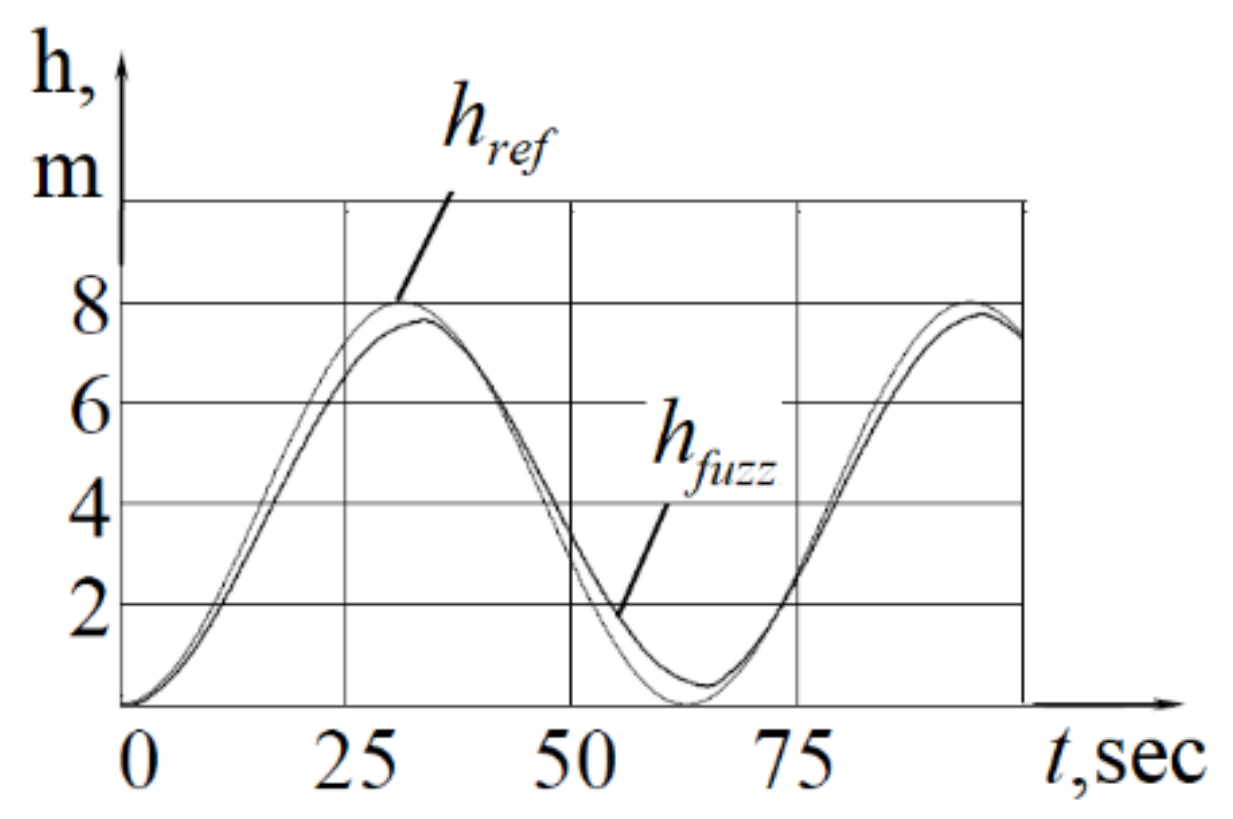
With a harmonic given signal, fuzzy controllers tuned to a step input signal were ineffective. The results of modeling the operation of a control system based on an FC with three symmetric triangles are shown in Figure 9. In this case, the error was 34.3 m∙s, and the maximum absolute error in depth was 0.5 m.
The analysis showed that in order to improve the operation of the control system, it is necessary to increase the weight of the error in speed , which is achieved by increasing the scale factor k2. The results of determining the coefficient k1 for various values of the coefficient k2 under the condition of minimizing the error are given in Table 1, where , are the total error for a stepwise and sinusoidal input signal, respectively; is the number of oscillations of the control action with a stepwise input signal, is the number of oscillations of the control effect when crossing through zero with a sinusoidal input signal (see Figure 10), and the maximum absolute value of the error when moving along a sinusoid.
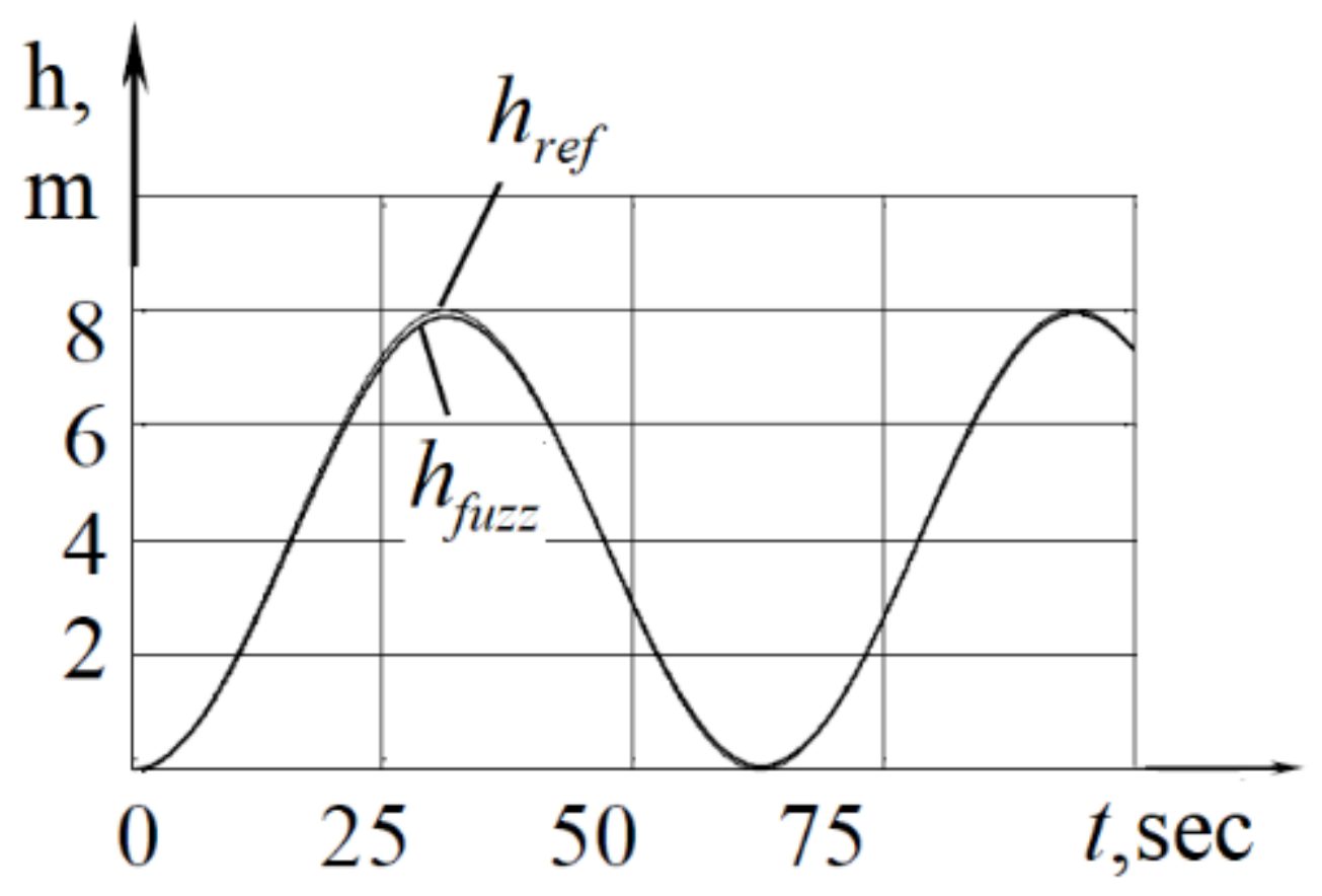
As shown by computational experiments, with an increase in the coefficient k2, the error decreases, which allows one to achieve high-quality control with a sinusoidal input signal. Figure 10 shows the simulation results for k2 = 100. It was also established that in this case for the step input signal, the error almost does not change, but the overshoot increases significantly, and the control signal becomes unacceptable for a real system since it has a large number of oscillations (see Table 1).
Thus, along with the fundamental possibility of achieving high-quality control of the FC with a harmonic input signal, the incompatibility of the coefficients k1 and k2 of FC was also found in the automatic control of vertical movement for stepwise and harmonic input signals. This means that each of the above modes requires a separate synthesis of FC coefficients, which limits the application of such a regulator in practice [11,12,13].
Studies of the other FC options discussed above showed even lower accuracy with a harmonic input signal and the need for appropriate adjustment of the coefficients.
8. Comparative Analysis of the Performance of a Fuzzy Control System and a System with PD Controller
To compare the results with traditional control systems, a proportional–derivative controller was synthesized, in which the control signal is calculated by the formula:
Since the model of the control object contains quadratic dependencies, it is impossible to perform the Laplace transform and obtain the transfer function of the control object. In this regard, the coefficients k1 and k2 were determined experimentally. The experimental results are shown in Table 2, and the best characteristics that were obtained with coefficients k1 = 60, k2 = 420 are shown in Figure 11.
As the simulation showed, the PD controller shows slightly worse results compared to the best results obtained when controlling a fuzzy controller. Thus, the total error is almost 9% larger, and the transition process time is 43% larger. For the harmonic input signal, the following quantitative characteristics of control quality were obtained: m∙s, maximum error m, which almost does not differ from the adjusted fuzzy controller.
9. Conclusions
When creating marine robotic systems, many different methods and devices for the interaction of vehicles with various types of carriers, both submarine and surface class, are being developed. These areas of research are important for both the civil and military industries.
Fuzzy logic serves mainly to process incomplete information, model human knowledge, and make informed decisions. It is also commonly used for real-time monitoring of technological processes, as well as solving problems associated with the practical implementation of technological process control systems. The use of fuzzy logic in control systems can significantly reduce operator intervention in the control process, which will enable the development of new control methods more adapted to the industrial environment.
Thus, the main advantage of fuzzy control is modern PLC programming systems. Such systems have built-in fuzzy control libraries and an easy-to-learn graphical interface which facilitates the adjustment of the automatic control system.
Calculation of the intensive processes for the ship industry is complex, which makes it difficult to automate them. Therefore, it seems relevant to analyze the methods of ensuring the required quality of regulation of the drying process.
The analysis of the quality of regulation, which was carried out with disturbances going through the channels of assignment, regulation, and parametric disturbance, is comparative and allows us to highlight the main advantages. The quality of regulation was determined by the following characteristics: dynamic error, degree of damping, regulation time.
Systems using fuzzy algorithms are nonlinear and the type of transient processes in such automatic control systems completely depends on the shape and size of the disturbing effect.
For small, limited in magnitude and rate of change values of the error signal, the fuzzy and classical PI algorithms are dynamically equivalent.
When the signal exceeds the mismatch or the limits of the normalized range, the saturation effect appears, that is, the fuzzy algorithm becomes significantly nonlinear.
A system with a fuzzy controller is much faster than a system with a PI controller. The dynamic error of a system with a fuzzy controller differs only slightly from the dynamic error of a system with a PI controller.
Thus, we can conclude that fuzzy control surely surpasses classical PI control in a number of characteristics.
Fuzzy controllers can be used independently to regulate process parameters, as well as in traditional PI and PID controllers for a significant increase in their characteristics.
This study provided the design of a fuzzy motion control system of an autonomous underwater vehicle. A comparison of the functioning quality of the designed fuzzy controller with the PD controller is made for step control and harmonic control, and various types of exogenous disturbances are investigated. It is shown that the designed fuzzy controller provides a higher quality of control compared to the PD controller.
The proposed fuzzy controller provides high-quality control of the plant under uncertainties and exogenous disturbances.
Author Contributions
Conceptualization, A.Z. and S.C.; methodology, A.F.; software, A.Z.; validation, A.F., S.C. and A.Z.; formal analysis, A.F.; investigation, A.Z.; resources, A.F.; data curation, S.C.; visualization, A.Z.; supervision, A.Z.; project administration, S.C. All authors have read and agreed to the published version of the manuscript.
Funding
This research received no external funding.
Conflicts of Interest
The authors declare no conflict of interest.
References
- Goheen, K.R.; Jefferys, E.R. Multivariable Self-Tuning Autopilots for Autonomous and Remotedly Operated Underwater Vehicles. IEEE Ocean Eng. 1990, 15, 144–151. [Google Scholar] [CrossRef]
- Muraleedharan, R.; Osadciw, L. Jamming attack detection and countermeasures in wireless sensor network using ant system. Proc. SPIE Int. Soc. Opt. Eng. 2006, 6248, 62480G. [Google Scholar] [CrossRef]
- Marir, S.; Chadli, M. Robust admissibility and stabilization of uncertain singular fractional-order linear time-invariant systems. IEEE/CAA J. Autom. Sin. 2019, 6, 685–692. [Google Scholar] [CrossRef]
- Kuznetsova, L.V.; Firsov, A.N. Simplified solution to the problem plane-parallel motion partial control of an autonomous rigid body in incompressible stratified viscous fluid. IOP Conf. Series Mater. Sci. Eng. 2021, 1047, 12190. [Google Scholar] [CrossRef]
- Bernalte, S.P.J.; Papaelias, M.; Márquez, F.P.G. Autonomous underwater vehicles: Instrumentation and measurements. IEEE Instr. Measure. Mag. 2020, 23, 105–114. [Google Scholar]
- Sun, Q.; Chen, J. Design of an Adaptive Depth Controller for an Autonomous Underwater Vehicle. In Proceedings of the IEEE 2016 8th International Conference on Intelligent Human-Machine Systems and Cybernetics (IHMSC), Hangzhou, China, 27–28 August 2016; pp. 288–291. [Google Scholar]
- Kang, S.; Rong, Y.; Chou, W. Antidisturbance Control for AUV Trajectory Tracking Based on Fuzzy Adaptive Extended State Observer. Sensors 2020, 20, 7084. [Google Scholar] [CrossRef]
- De Aquino Limaverde Filho, J.O.; Fortaleza, E.L.F. Control of underactuated AUVs: A flatness-based approach. In Proceedings of the OCEANS 2014—TAIPEI, Taipei, Taiwan, 7–10 April 2014; pp. 1–6. [Google Scholar] [CrossRef]
- Zhou, J.; Ye, D.; Zhao, J.; He, D. Three-dimensional trajectory tracking for underactuated AUVs with bio-inspired velocity regulation. Int. J. Naval Arch. Ocean Eng. 2018, 10, 282–293. [Google Scholar] [CrossRef]
- Liang, X.; Wan, L.; Blake, J.; Shenoi, R.; Townsend, N. Path following of an Underactuated AUV Based on Fuzzy Backstepping Sliding Mode Control. Int. J. Adv. Robot. Syst. 2016, 13, 122. [Google Scholar] [CrossRef] [Green Version]
- Zhilenkov, A.; Chernyi, S. Models and algorithms of the positioning and trajectory stabilisation system with elements of structural analysis for robotic applications. Int. J. Embedded Syst. 2019, 11, 806. [Google Scholar] [CrossRef]
- Sokolov, S.; Zhilenkov, A.; Chernyi, S.; Nyrkov, A.; Mamunts, D. Dynamics Models of Synchronized Piecewise Linear Discrete Chaotic Systems of High Order. Symmetry 2019, 11, 236. [Google Scholar] [CrossRef] [Green Version]
- Chernyi, S.G.; Erofeev, P.; Novak, B.; Emelianov, V. Investigation of the Mechanical and Electromechanical Starting Characteristics of an Asynchronous Electric Drive of a Two-Piston Marine Compressor. J. Mar. Sci. Eng. 2021, 9, 207. [Google Scholar] [CrossRef]
Figure 1.
Structure of a stratified continuous medium.

Figure 2.
Trajectory of AUV.

Figure 3.
Illustration of the hydrodynamic forces acting on the ball-wing system.
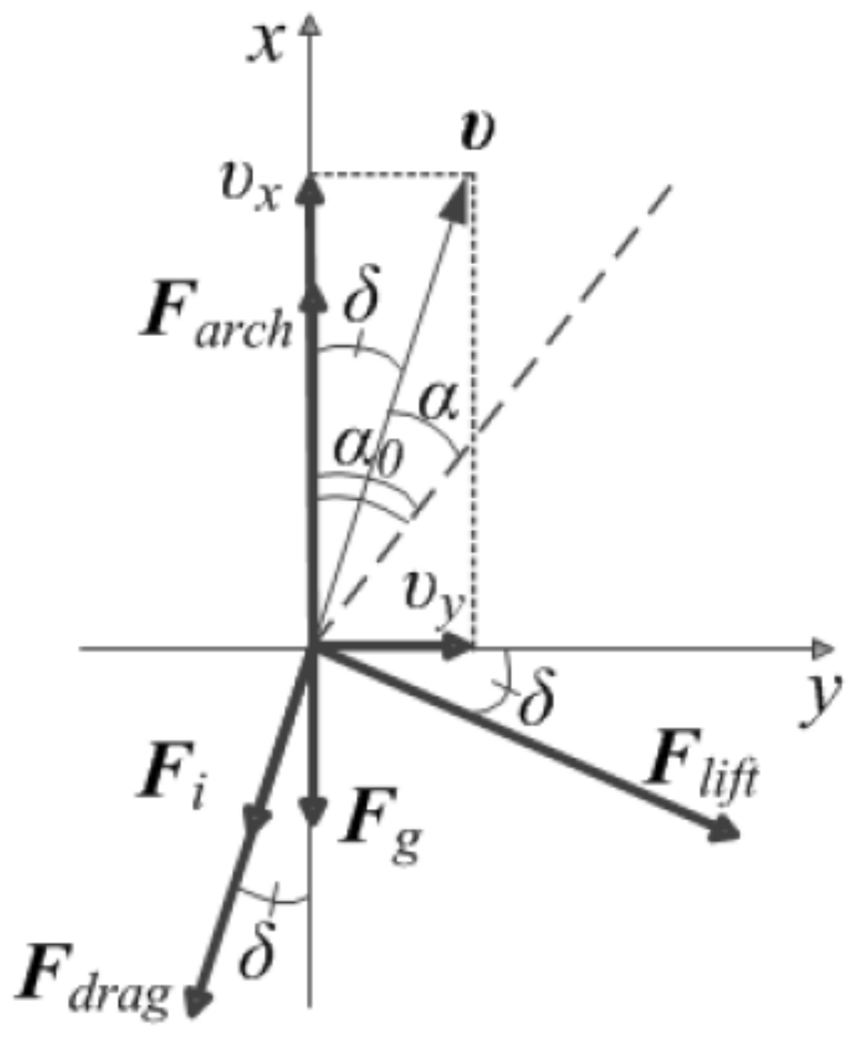
Figure 4.
Functions of the terms of a fuzzy controller.

Figure 5.
The surface of the fuzzy controller.

Figure 6.
Simulation of an underwater robot using typical blocks of the Simulink package and proposed mathematical model.
Figure 6.
Simulation of an underwater robot using typical blocks of the Simulink package and proposed mathematical model.
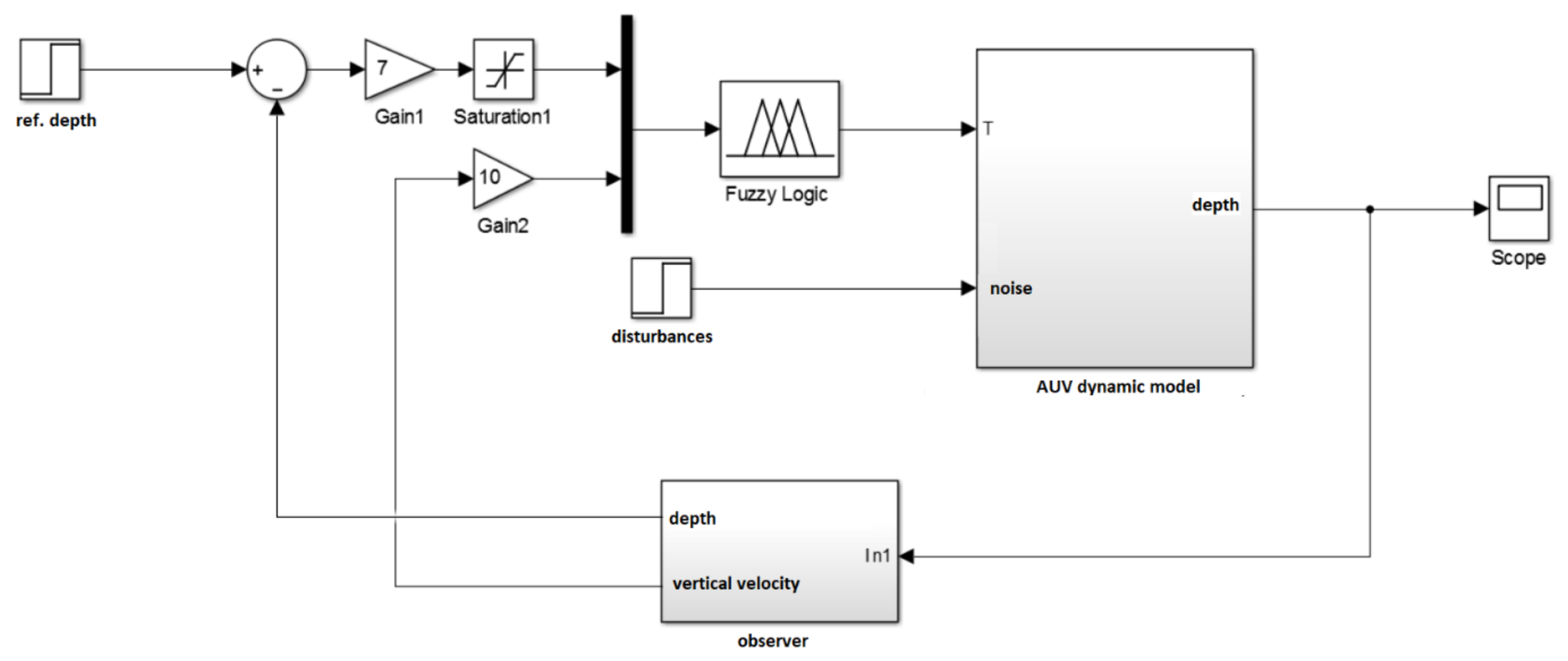
Figure 7.
Graph of the given and the current depth of the AUV versus time without noise or external disturbances.
Figure 7.
Graph of the given and the current depth of the AUV versus time without noise or external disturbances.

Figure 8.
Graph of the given and the current depth of the AUV versus time with harmonic exogenous disturbance.
Figure 8.
Graph of the given and the current depth of the AUV versus time with harmonic exogenous disturbance.

Figure 9.
Control of the vertical movement of the AUV with a harmonic input signal: href is a graph of the depth; hfuzz—control signal.
Figure 9.
Control of the vertical movement of the AUV with a harmonic input signal: href is a graph of the depth; hfuzz—control signal.

Figure 10.
Control of the vertical movement of the MPR with a regulator tuned to a harmonic input signal: href is a graph of the depth; hfuzz—control signal.
Figure 10.
Control of the vertical movement of the MPR with a regulator tuned to a harmonic input signal: href is a graph of the depth; hfuzz—control signal.

Figure 11.
The transition process of stepwise changes in the depth of the AUV with PD-regulator: a graph of changes in depth.
Figure 11.
The transition process of stepwise changes in the depth of the AUV with PD-regulator: a graph of changes in depth.


Table 1.
Dependence of scale factors on harmonic input signal.
| Indicator | Arguments | |||||
|---|---|---|---|---|---|---|
| k1 | 0.64 | 0.61 | 0.61 | 0.62 | 0.61 | 0.62 |
| k2 | 10 | 20 | 30 | 40 | 50 | 60 |
| 3 | 4 | 5 | 6 | 6 | 7 | |
| , m∙s | 130.0 | 129.7 | 129.7 | 129.6 | 129.7 | 129.7 |
| 1 | 1 | 2 | 2 | 2 | 2 | |
| , m | 1.00 | 0.60 | 0.42 | 0.33 | 0.27 | 0.23 |
| , m∙s | 56.0 | 29.1 | 19.6 | 14.92 | 12.10 | 10.22 |
Table 2.
The values of the coefficients of the PD controller.
| Indicator | Arguments | ||||||
|---|---|---|---|---|---|---|---|
| k1, V/m | 200 | 150 | 100 | 90 | 80 | 70 | 60 |
| k2, V/m | 2000 | 1500 | 1000 | 900 | 700 | 500 | 420 |
| , m∙s | 153.8 | 153.9 | 154.0 | 154.0 | 148.1 | 141.6 | 141.2 |
| k1, V/m | 40 | 35 | 30 | 25 | 20 | 15 | 10 |
| k2, V/m | 280 | 250 | 210 | 180 | 150 | 120 | 80 |
| , m∙s | 141.3 | 141.9 | 141.4 | 142.3 | 143.7 | 146.3 | 147.4 |
Publisher’s Note: MDPI stays neutral with regard to jurisdictional claims in published maps and institutional affiliations. |
© 2021 by the authors. Licensee MDPI, Basel, Switzerland. This article is an open access article distributed under the terms and conditions of the Creative Commons Attribution (CC BY) license (http://creativecommons.org/licenses/by/4.0/).
Share and Cite
MDPI and ACS Style
Zhilenkov, A.; Chernyi, S.; Firsov, A. Autonomous Underwater Robot Fuzzy Motion Control System with Parametric Uncertainties. Designs 2021, 5, 24. https://0-doi-org.brum.beds.ac.uk/10.3390/designs5010024
AMA Style
Zhilenkov A, Chernyi S, Firsov A. Autonomous Underwater Robot Fuzzy Motion Control System with Parametric Uncertainties. Designs. 2021; 5(1):24. https://0-doi-org.brum.beds.ac.uk/10.3390/designs5010024
Chicago/Turabian StyleZhilenkov, Anton, Sergei Chernyi, and Andrey Firsov. 2021. "Autonomous Underwater Robot Fuzzy Motion Control System with Parametric Uncertainties" Designs 5, no. 1: 24. https://0-doi-org.brum.beds.ac.uk/10.3390/designs5010024