
Assistive Devices: Technology Development for the Visually Impaired
by
 , , and
Jorge Rodolfo Beingolea
1,* ,
,
Miguel A. Zea-Vargas
2, 
Renato Huallpa
2 ,
,
Xiomara Vilca
2,
Renzo Bolivar
2 and
Jorge Rendulich
2
1
Department of Electronic Systems Engineering, University of São Paulo, São Paulo 05508-010, Brazil
2
Department of Electronic Engineering, Universidad Nacional de San Agustin de Arequipa, Arequipa 04001, Peru
*
Author to whom correspondence should be addressed.
Designs 2021, 5(4), 75; https://0-doi-org.brum.beds.ac.uk/10.3390/designs5040075
Submission received: 10 October 2021
/
Revised: 27 October 2021
/
Accepted: 24 November 2021
/
Published: 27 November 2021
(This article belongs to the Special Issue Design and Control of Collaborative Robotic Solutions and Wearable Assistive Robots to Enhance Human Capabilities)
Abstract
:Technology has been contributing significantly to the development of assistive devices for disabled persons (DPs). Many of these devices aim to assist people who are blind or visually impaired, providing them with friendlier ways to interact with their surroundings (obstacles, objects, and navigation). However, the high cost of these devices makes it difficult for DPs to purchase them. The development of an assistive device kit to be used by the visually impaired in controlled environments (indoor) or urban spaces (outdoor) is presented in this work with a didactic and detailed approach. This low-cost kit (USD 50 per device) consists of a Smart Cane, Smart Cap, and Smart Glove. The methodology addressed aims to support and encourage the reproduction, customization, and manufacture of new assistive devices with low cost and wide applicability. The devices are functional, benefit usability, and, due to the characteristics of the project and the materials used in their construction, do not impact the ergonomics of the visually impaired or disabled person who may use these devices. The devices that integrate the assistive kit can be used independently or combined. In addition to having detection, fall-control, navigation, and real-time tracking functions, they are independent of additional local infrastructure for their use.
1. Introduction
Topics related to disabled person (DPs) and accessibility have increasingly gained society’s attention. Consequently, DP became more frequent and visible in various environments in the urban space. These advances are clear; however, to maintain their acquired rights and benefit from the advantages of living in an urban center, DPs still need to face several obstacles. Some of the limitations confronted when DPs need to move into the urban space are scarcity or total absence of adapted information, physical barriers, passersby and drivers who do not respect or give priority to them, lack of security, and lack of empathy.
Wearable [1], Internet of Things (IoT) [2], and Smart Clothing [3,4] technologies have a strong potential to improve the experience that DPs have with the city, providing the necessary technological interfaces so that they can move, autonomously, in different environments of urban spaces. In addition, DPs can have access to highly functional devices due to their low cost. Furthermore, these devices can be provided within controlled areas, such as university campuses, monitored visitation centers, museums, zoos, and parks, among others.
This study is based on the hypothesis that intelligent cities demand the project and development of technologies that allow the democratization of access to public spaces [5] and services in a personalized way on a straightforward usability model [6,7]. Therefore, it is essential to develop assistive devices for the inclusion of DP within the urban space with the greatest possible autonomy. Moreover, a didactic approach is also necessary for the straightforward reproduction of these low-cost technologies.
In this study, a set of assistive devices for DPs is presented. The specifications used in the design and manufacture of these assistive devices consider the usability, ergonomics, and restrictions expressed by people with visual impairments who participate in the project. Low-cost electronic components are used to manufacture these devices, where the accuracy of the device’s functions is maintained.
The devices or gadgets kit has the following features, where there is the possibility of customization:
- Ultraviolet (UV) radiation monitoring and alerts module;
- Geolocation module—GPS (used for device tracking);
- Obstacle detection module;
- Fall detection and warning module (designed for DP and elderly people);
- Object detection module in controlled environments;
- Mobile and web interfaces.
Literature Survey
In recent years, the concept of intelligent cities [8] has become increasingly evident. Consequently, cities’ remodeling and their spaces have been subjected to new organization and management models. These new concepts and models guide the development of technologies that allow the inclusion of disabled person as part of this scenario, providing accessibility at all times.
Solutions for intelligent cities and the diversification of assistive applications have gained significant notoriety for their innovative features, functional aspects, or low cost. Among these applications and devices, some help in locating [9], locomotion, identifying obstacles, and talking [10]. With the advent of Artificial Intelligence (AI) and the Internet of Things (IoT), many projects have become a reality. Table 1 shows the list of applications and assistive and accessibility devices examined.
As shown in Table 1, the initiatives listed present descriptions, functional models, and an adequate representation of some IoT technologies. Concepts and functionalities have already been addressed in a vast number of initiatives by several authors [25,26,27,28,29,30,31], and they are increasingly customized. However, the operation and production logic does not change, the observed phenomena remain the same, and each component’s cost is extremely high, making the prototypes not only heavy or expensive to implement but also challenging to reproduce.
In general, the works presented in Table 1 are difficult to reproduce. This occurs for several reasons, such as lack of more detailed information, high cost, or because the authors use prototyping with proof-of-concept characteristics that do not consider aspects of usability, volume, and weight, among other characteristics. Consequently, making it complicated for the DP to adapt to the device’s use and affecting their ergonomics.
This study aims to innovate in the development of assistive devices, using electronic components and low-cost manufacturing processes. Additionally, the reproduction and customization of the designed functions will be facilitated with a detailed design approach. Moreover, a didactic and systematic method is presented, highlighting the challenges and features of prototyping and showing a clear contribution to the design of assistive devices as a final product.
2. Materials and Methods
First, an analysis of the most recent studies on the development of devices for the visually impaired is performed, seeking to highlight the differences between the existing devices and those developed in this study (Table 1).
The assistive kit project starts with a brief description of the functionality of each device. The functionality specification process is the result of a careful study with members of the research group who have a severe visual impairment. Usability and ergonomics criteria are also considered, making the final designed devices easy to operate and light in weight due to their composition of materials, such as aluminum and plastic.
The detailed description of the device specification, manufacturing, and testing processes is intended to facilitate the reproduction and customization of the assistive kit. Circuit designs, as well as 3D design, programming codes, and function testing are also made available in this work.
The assistive device kit was modeled, according to its functionalities, to be used in several environments of urban spaces. The validation environment was recreated within the university space. Due to its size and diversity of environments, it was possible to recreate situations and challenges common to DPs daily life. The kit consists of three devices: Smart Cap, Smart Cane, and Smart Glove, whose functionalities will be further described.
2.1. Smart Cane
The Smart Cane is designed as a DP support device. The functions of the Smart Cane are presented in Figure 1, and its execution flow is illustrated in Figure 2. The description of each of the functions is given below.
- —
- Obstacle detection: consists of ultrasonic sensors that detect obstacles at distances of up to 3 m. When the obstacle is detected, an alert is transmitted through a vibrotactile system (vibrating bracelet) connected to the stick sleeve. It is important to note that the closer the DP is to the obstacle/object, the greater the bracelet’s vibration (vibration motor of the bracelet).
- —
- Geolocation: the module embedded in the stick is a function that continues to act since its operations are initialized. After initializing, the module takes an average of 20 s to obtain the DP’s location coordinates. When obtained, the coordinates are sent to the MQTT (Message Queuing Telemetry Transport) Broker in message format, containing the stick and user IDs. In the initial experiments, the module was programmed to transmit every 10 s; however, this parameter can be changed at any time. In addition, the information is stored in a database (SQLite) so that, later, the DP’s displacement can be represented at the interface level.
- —
- Navigation: it is performed with the detection and recognition of color lines (red, green, blue and black) that signal the different paths followed by the DP. When a color is detected, the DP is alerted (audio) to decide which course (color) to follow. Color lines are widely used in public and private offices, health centers, and other places. In countries such as Peru and Brazil, this procedure is regulated by law.
- —
- Alert generation: the detection and navigation information are translated into real-time audio.
The number of cores that will be used is determined at system start-up (for example, the SPN32 has 2 cores). Then, the communication protocols and routines used for the calibration of the modules and sensors integrated into the Smart Cane are started.
2.2. Smart Glove
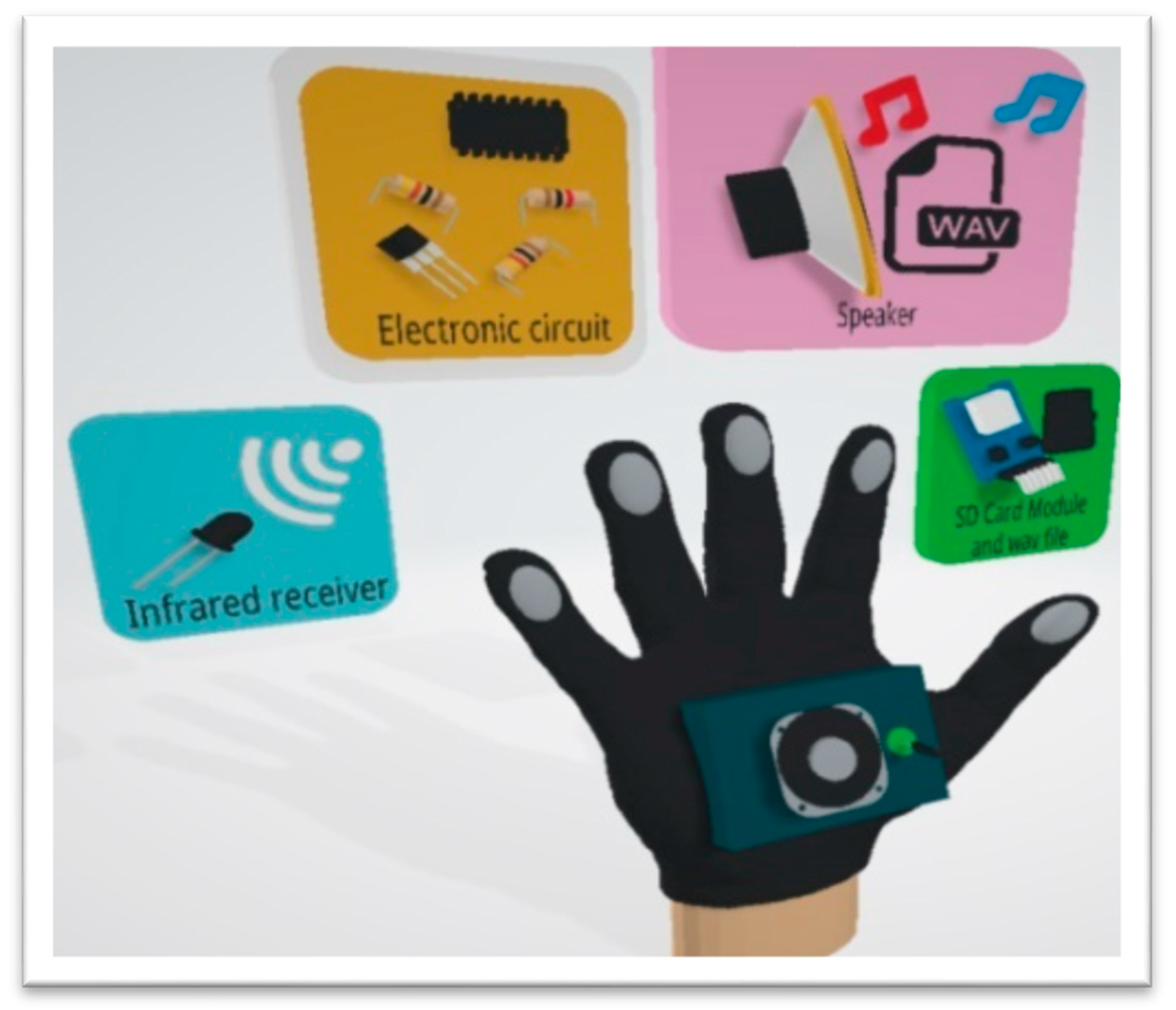
Designed as a support device for DPs, the Smart Glove (SG) is developed with the following two main modules.
- —
- Interface Module: consists of an RFID tag, which acts as an interface with a device known as the smart module, whose function is to present information about the location (room, laboratory, building, etc.) to the DP. The device was installed at the access (doors and near the doors) of the electronic engineering building and the laboratories’ entrance. In its first version, the module presents a straightforward function. In anSQLite database, it stores audio information about objects and people registered within the environment. This information can then be accessed by the DP using an RFID tag integrated with the SG (Figure 3). When DPs bring the tag closer to the smart module, it presents a menu with audio information about objects and people registered in the environment. The expectation is that the smart module will be automatically powered and updated with information about when people enter and leave the environment and when objects are placed or removed. Therefore, the DB (Data Base) must be updated in real-time.
- —
- Identification Module: consists of an infrared (IR) circuit designed to operate as a receiver IRrx (glove) and transmitter IRtx (object). The IR circuit is connected to a microcontroller that runs the detection and translation algorithm of the object’s information. Operationally, the IRrx on the glove communicates with the IRtx on the object, and this occurs when users place their hands on these objects. The IRtx sends its identification (object code), and the IRrx searches for it in its internal database and translates the object’s information into audio to be heard by the DP (Figure 4).
Information about the objects is stored in the Smart Glove, helping in the identification process. Currently, the Smart Glove DB has data from 100 objects, which makes it an autonomous device. In the current version, the update process is performed using the USB interface; however, the device can integrate a wireless or Bluetooth module to enable remote updating.
The Smart Glove operation process is described in the diagram in Figure 4. An IR transmitter module (Tx) is installed on all objects to be identified (Computer—ID:01, Laptop—ID:02, among others). Once installed, Tx issues a signal with the object ID to which it has been associated (Tx Object).
The IR receiver module (Rx), integrated into the Smart Glove, starts scanning the environment and identifies the objects using the ID emitted by each transmitter (TxObject), performing a search in the local database. As a result, the Smart Glove produces audio with the information of the identified object.
The transduction is performed by an algorithm that receives the TxObjectID and retrieves the information from the DB and the audio that contains the object’s information. In this first version, the object’s information must be previously registered in the DB with an HTML interface, as well as the audio file. However, the expectation is that the algorithm will translate the object’s information (text) into audio format if it does not already exist in the DB. Therefore, possible solutions should be explored due to the high processing cost that this function may demand.
2.3. Smart Cap
The Smart Cap is designed as a DP assistive device and consists of four functional modules. The modules described below are operationally independent of each other; however, their information is integrated at the interface level (Figure 5).
- —
- Falls control module: designed to identify whether DPs have suffered a fall, especially sudden falls. The module uses a LilyPad ADXL 335 sensor, which is intended for use in wearable applications. This sensor has three terminals for each of its measurement axes, and the slope level determines the voltage delivered for each terminal. When the module identifies the user’s fall, it triggers a message on the GPRS module, sending the fall’s location and intensity. This message is forwarded, in real-time, to friends or family members previously registered.
- —
- Detection module: consists of HC-SR04 sensors and a vibrotactile system composed of a LilyPad vibrating micromotor, which issues alerts as the identification of objects is confirmed. The intensity of the generated alert is programmed as DPs approach the obstacle. The module detects objects and obstacles up to 3 m away and issues a warning from 1.5 m away (Table 2). The device acts as a complement to the Smart Cane.
- —
- UV module: designed using the ML851 UV sensor integrated with Arduino Nano. The sensor allows DPs to receive information about radiation levels, and a buzzer emits an alert instructing the user to use sun protection products.
- —
- Geolocation Module: consists of an A9G (GSM-GPRS) embedded in the device, which is a web monitoring environment that uses, in its first version, the Google Maps API. The module does not work as a navigation assistant but as a device for locating DPs inside and outside the university premises.
The functionalities in each of the devices are operationally independent of each other and integrated only at the interface layer level. Alerts and environment information are already presented to users, whether in the form of audio or vibration. Later, the information is encapsulated and forwarded to a microservice environment. In this environment, friends or family can observe the information in real-time or make inferences about the history of events at any other time.
The Smart Cap operation process is described in the diagram in Figure 6. The process starts with the initialization of the sensor calibration variables. The first module to be initialized is the UV radiation detection and alert module. It is connected to a buzzer that emits alerts when there is an increase in UV radiation. After each reading, the information is transmitted via MQTT protocol using the GPRS module to a Web Service that stores the history of the collected data. The second module to be started is the obstacle detection module. It is connected to a mini vibration motor that vibrates when objects or obstacles are close, thus notifying the user. The last module to be initialized is the fall control module. It transmits data via MQTT using the GPRS module and sends an SMS to the mobile number of the person registered in this module, which can be a relative or friend. The SMS contains information about the event (time, time on the ground, and speed of fall) and the location of the disabled person so that they can be rescued.
Programming for communication and sending of data processed via GPRS is performed using AT commands. One of the advantages of using the A9G module is that it has commands that allow transparent communication with the MQTT (MQ Telemetry Transport) protocol, and it is widely used and supported in IoT applications.
3. Results
The specification of functions resulted in the detailed description of the modeling, simulation, and fabrication processes of all devices parts of the assistive kit. All processes have been carefully detailed, and the source of the projects is shared in this section (circuits, 3D designs, simulation). The description of the processes is described for each device to emphasize the challenges encountered, allowing for straightforward reproduction of the experiences and results achieved.
3.1. Hardware Design
3.1.1. Smart Cane—Architecture
It consists of the Obstacle Detection, Geolocation, Navigation, and Alert Generation modules. The ESP32 microcontroller was chosen because it has a two-core processor, making it possible to perform tasks simultaneously.
The system previously stores a predefined vocabulary of words and audio, which are reproduced using an 8-bit digital/analog converter (DAC) integrated into the ESP32 processing module. As the signal is low, it is necessary to integrate an amplifier board before going to the output, where there is a mini loudspeaker coupled.
Components:
The Smart Cane has a sequence of characteristics regarding its component structure, which are considered in Table 2.
The first version of the devices was implemented using the low-cost components described in Table 2. However, the project seeks to maximize the precision characteristics necessary for devices to be used in open environments of urban spaces, in which eventual failures could impair the DP’s mobility capacity. The final device is finally shown in Figure 7.
The SPN32 has only the function of processing and integrating Smart Cane’s internal devices (color sensor, ultrasonic sensor, and mini vibrating motor). Communication functions are provided by the GSM/GPRS/GPS module, which is used both to track the device and to transmit all navigation information to the web environment. The structure, except for the pipe, is made of plastic material and entirely manufactured in a 3D printer.
The connection diagram and the graphical mapping of the components can be seen in the Appendix A (Figure A1).
3.1.2. Smart Glove—Architecture
The Smart Glove consists of the interface module (smart module) and the Identification Device. The IR photoreceptor receives the object ID signal (IRTx) at the receiver, passing through the BC584 transistor that functions as a switch. This signal goes to the microcontroller, which processes the information and performs a search for the WAV file in the DB, stored on the SD card installed in the microcontroller. Finally, the audio file with information about the object is played. In Figure 8, it is possible to observe the device’s final version. The components of the Smart Glove are described in Table 3.
It is possible to observe the schematic of the device acting as a transmitter (object identifier) on the Appendix A Figure A2 and the connection diagram—IR of the receiver (in the glove) on the Appendix A Figure A3.
The receiving circuit consists of a phototransistor that is sensitive to infrared light. The operating logic is simplified by the use of the UART communication protocol, in which the voltage level corresponding to the “sleep” state is the logical value “1”. In practice, this logic allows controlling the sensor activation. When the UART receiver is in an idle state, there must be no infrared light present (the infrared sensor is inactive).
The comparator “compares” the level of the reference voltage with the voltage coming from the external pins (such as IR_Q1_C+ and IR_Q2_C+) with the following logic:
If , the logical state will be “1”; otherwise, it will be “0”.
If , the logical state will be “1”; otherwise, it will be “0”.
To achieve the established UART logic, comparator 4 is used to connect the phototransistor (corresponding to pins IR_Q2_C+ and IR_Q2_E). Then, the output signal of comparator 4 (OUT_COMP4) must be denied to comply with the mentioned logic, so OUT_COMP4 is interconnected with IR_Q1_C+. Therefore, the resulting signal OUT_COMP3_RX directly feeds the RX pin of the Arduino nano with the logical state “1” when there is no infrared light (IR_Q1_C+ uses comparator 3).
The transmitter circuit consists of an infrared LED connected to the TX pin of the Arduino Nano, and as long as the UART communication protocol is used, the voltage level corresponding to the “sleep” state is the logical value “1”. As it is better to turn off the infrared LED when the UART transmission is in the idle state, the use of two transistors in the pre-cut saturation setting is considered to deny twice the UART’s original logical value.
In Figure 9, the IR layout is presented. It should be noted that the only difference in the structure of both receiver and transmitter is in the program that runs on each one of them, determining their functions.
3.1.3. Smart Cap—Architecture
The Smart Cap consists of ultraviolet light sensors, an acceleration sensor, an ultrasonic proximity sensor, a buzzer, a vibrating motor, and a GSM module with integrated GPS (Figure 10a,b). The electrical scheme of operation and connection can be seen on the Appendix A Figure A4. The electronic components of the Smart Cap are described in Table 4.
The GSM/GPRS/GPS module is used both for tracking the device and for sending event information (alerts, UV radiation, falls) and navigation information to a web environment.
The devices use several microcontroller architectures to respond only to specific demands of the application without causing high energy consumption. Likewise, shielding is manufactured for almost all components integrated into the devices since the microcontrollers used do not have enough I/O to operate the diversity of components integrated into them.
3.2. Experiments and Functionality Testing
Developing low-cost devices results in also requiring the use of lower-priced electronic components. In many cases, they have low accuracy, which can compromise the accuracy of the final product’s functions.
The model environment used to simulate all the city’s events is the set of buildings of the Electronic Engineering Department located on one of the university campuses of the National University of San Agustin (UNSA) in the city of Arequipa, Peru. In this project, situations of obstacles, identification of objects, and identification of hallways are recreated in the space composed of laboratories, classrooms, and secretariats of this department. Open environments, such as living spaces and sports courts, are used to recreate fall situations and UV radiation control.
Some test tools have been developed to evaluate different functions of each device (available at https://cutt.ly/vcNjPIO (accessed on 25 November 2021). These tools are used in experiments to assess the accuracy of devices in their interaction with events in the physical environment for which they were designed, such as color trail reading (navigation), object detection, tracking, fall control, UV radiation, and object identification.
3.2.1. Smart Cane—Functions
3.2.2. Smart Glove—Functions
The smart glove features two modules, receiver and transmitter, which are tested for their range and accuracy of readings.
For the Smart Glove identification device, a BC547 sensor (photodiode) was used. It provides a range of up to 30 cm for the projected circuit (Figure 10), although the device (IRtx—IRrx) has been set to operate within a range of 10 cm. It is also possible to increase the range by including an amplifier circuit and power supplies of 1 to 2 amps (A). This was not necessary in this work, as it was observed that DPs usually place their hand as close as possible to the object, which is an intuitive act since they seek to know about the object with which they want to interact.
Table 7 shows the results of the experiments performed to validate the response time according to the distance. The results indicate the need to improve the code. The results also include the detection, search, and reproduction of object information, which is the complete identification cycle.
The ultrasonic sensors range of object detection is approximately 1.5 m under a direct view, maintaining that same accuracy with angles of up to 30 degrees. Likewise, the sensors can be easily calibrated via software for detection at distances up to 0.50 cm from the object. The evaluation of the reaction time of the visually impaired after receiving the alert of proximity to an object and or obstacle will also be considered.
Although the infrared circuit range experiments designed for the Smart Glove presented in Table 6 are restricted to distances of up to 10 cm, it is possible to adjust it to an efficient range of up to 20 cm to the object. It is important to note that working with a shorter range reduces the possibility of interference from other devices (transmitters) near the Smart Glove receiver.
Regarding the use of GPS in both Smart Cane and Smart Cap, the accuracy is 3 m in indoor environments. The GPS was tested under several conditions (static and motion modes).
The described precision tests, as well as all developed devices’ functions, are validated using a test algorithm designed for each device (http://bit.ly/3arbsAm (accessed on 25 November 2021)). The algorithms are executed manually, allowing the testing of each component and function developed for each device.
3.2.3. Smart Cap—Functions
Smart Cap includes a fall-control module in which some experiments were performed to determine the module’s accuracy. Additionally, it is possible to use this fall-control module as an individual function, not integrated with the Smart Cap. Believing that the fall control function on the Smart Cap is innovative, the objective is to design a self-contained package that allows the device to be embedded in the DP’s clothing. The values shown in the graph in Figure 12 correspond to the average values obtained from a total of 1000 readings performed.
The graph (Figure 12) represents the variation of the X and Y angles that measure the Smart Cap’s inclination to the horizon (where X and Y are ideally 0° or 360°) under three different conditions: DP in stationary (static) and DP in movement positions (smooth movement and sudden movement).
In the stationary position, the variation of angles is negligible as they do not exceed 5 degrees. For the case of the movement positions, these vary considerably, especially with the smooth movement, which allows collecting more samples when the Smart Cap is in an extreme position (when X and Y vary at least 40° from 360° or 0°).
Even if the peaks reach 25° in X and Y, this is not enough to be considered as a fall because the Smart Cap is prepared for continuous head movement in the three states presented. Therefore, the fall sensor is efficient in the common and daily activities of a DP.
Smart Cane and Smart Cap use the same A9GPS module and both use it for tracking and communication functions. This is the module that allows the tracking of devices and the sending of data accessed by the API and by the web platform.
Regarding the GPS module, precision was measured in two states: static and motion with a total of 250 tests. For the static state, an average error of 4 m is obtained from the coordinate provided by Google with a deviation of 1.67 m. The error is acceptable for this level of integration. When in motion, it is understandable that precision is reduced. Considering that the speed was not constant, it ranged from 2.4 to 2.8 km/h, obtaining an average error of 7.22 m and a deviation of 2.27 m. This large error obtained can be attributed to the sum of Google Maps and Smart Cap errors, which, due to the fluctuating speed and its considerable magnitude, makes synchronization difficult.
Finally, experiments were performed on the use of the UV radiation control module (Table 8). As UV varies according to time and place, it is necessary to compare the values obtained with a recognized institution, in this case, the SENAMHI (National Service of Meteorology and Hydrology of Peru).
The 1000 samples were taken in the city of Arequipa (Perú), where the UV is mainly extreme (greater than 11 on the scale).
The main reasons for the large error obtained are that the values given by SENAMHI are the maximum that can be detected and that they are based on an ideal model (completely clear sky, height at sea level, and solar intensity at noon). These factors, in contrast to the Smart Cap’s advantages of size, price, and affordability, make it clear how effective it is to implement it directly into the Smart Cap.
In conclusion, all results show adequate precision in each of the functions designed for the assistive devices kit and are within what was expected. The assistive kit represents an opportunity to increase the DP’s integration with its surrounding environments while providing functions to ensure its integrity. Due to its low cost and comfort, the kit provides practicality in the use of its functions, since the devices are light, small, and discreet, not impacting the ergonomics of the DP.
3.2.4. Usability Experiments
The development of assistive devices that support the inclusion and accessibility of people with disabilities within the urban space has been progressing within research and innovation centers, while software and hardware products are regulated by a set of standards and laws [32] imposed by different countries.
Developing assistive devices is not an easy task, as there must be an exhaustive analysis of the feasibility and usability of the functions and physical characteristics of each device. In the design of these devices, it is important to use electronic components and materials that are lightweight so that they do not impact the user’s ergonomics. Additionally, it is crucial that there is easy access and manipulation of the device by people with disabilities.
The usability experiments (Table 9) were performed on a small group of visually impaired people who were members of the research group. The criteria or indicators used were:
- (a)
- Number of tasks that can be performed by the device;
- (b)
- Function learning time;
- (c)
- Percentage of tasks completed on the first attempt;
- (d)
- Number of assistance requests;
- (e)
- Time spent on first use attempt;
- (f)
- Level of satisfaction;
- (g)
- Level of expectations.
Table 9 shows the results of the usability experiments carried out with researchers with visual impairments. The group is composed of two people, aged 19 years (DP-1) and 40 years (DP-2), both with total bilateral visual impairment. The results are presented and evaluated separately for each individual, due to the peculiarities that exist due to the difference in age and proximity to the use of technology.
Each device designed is capable of performing a number of task functions (Column A): Smart Cane (Navigation, Tracking and Obstacle Detection), Smart Cap (Obstacle Detection, UV Radiation Detection, Drop Detection and Tracking), and Smart Glove (Object Identification). All these functions are evaluated by the DP while using each device.
The experimental part of this project begins with a detailed presentation of the functions of each device for each DP. The results showed time differences in the learning process of the functions of each DP for each device (Column B). DP-1 was more receptive to the use of technology and, after a single training, was able to reproduce and access each function. DP-2, on the other hand, had difficulty in identifying the alerts (buzzer) emitted by the devices (obstacles and UV radiation), and their learning time for each device was double when compared to the results of DP-1. The learning/training activities for recognizing the functions and use of devices was repeated six times for each device in a total of six sessions held in two weeks.
The percentage of times the experiments were completed (Column C) was higher in the case of DP-1, including when considering the number of assistance requested (Column D), in terms of the number of times users needed help, either to remind them of access to a particular function or the meaning of an alert issued by the device.
The average usage time of the devices for each experience (Column E) is considered sufficient for an adequate assimilation of technologies by the DPs.
The level of satisfaction regarding the functions designed and made available in each device (Column F) was high, as well as the level of expectations in relation to the devices (Column G). For the Smart Glove (indicators of columns F and G), DP-1 showed a lower level of satisfaction and expectation when compared to other devices. This happened because DP-1 believes that there should be greater intelligence in the device, particularly that the Smart Glove should be able to recognize and learn about objects in the environment without the need to manually insert/update this information. DP-2, on the other hand, was satisfied, as they felt that an easy understanding of the environment was provided, whether at home or at university (controlled spaces).
Finally, the DPs concluded and argued that the devices are very functional and help them efficiently, meeting the expectations revealed by the users during the process of specifying the features for each device.
4. Discussion
The city becomes a source of unexpected events, unwanted surprises, and unforeseen events that generate anxiety, frustration, and waste of time for DPs. Furthermore, this unpleasant experience lived by DPs in urban spaces affects their notion of belonging to that territory and negatively impacts the citizen-inhabitant feeling. This diversity of facts and situations has become, in recent years, the primary motivator for professionals, researchers, companies, and governments to invest significantly in the development of technologies that improve people’s lives in the city.
In this project, the integration of IoT and Wearable technologies is considered to develop a kit of devices that provide DPs with a greater sense of autonomy within controlled and open environments such as urban spaces. The various devices that compose the first version of the assistive kit have functional characteristics. When integrated, these devices provide DPs with information about the environment, easy navigation of spaces, identification of objects, tracking the DP that is using them, tracking their devices, and the kit. As the devices have GPS modules, it is also possible for another person, relative, or friend to monitor the DP and devices’ location in real-time using a Web application. The assistive kit consists of a Smart Cap, a Smart Glove, and a Smart Cane.
Currently, the demand for solutions that support the inclusion of people with disabilities within the urban space is increasing. Consequently, it is necessary to adopt public policies to promote the development and insertion of services and urban infrastructure to support the independence of people with disabilities inside and outside urban spaces [33].
The concept of smart cities [34] has allowed exploring new initiatives that consider the DP within social infrastructure projects and urban services; however, the results must be evidenced in the long term.
Developing devices for DP is a challenge currently created not only by the lack of investment in the sector but also by the high cost of the final product, which, in most cases, makes access to these technologies unfeasible or difficult [35].
The purpose of developing this work, which leads to the careful specification of the assistive kit functionalities and, subsequently, to a detailed description of the projects and processes involved, is to encourage new initiatives that enable easy customization of the devices’ design and their functions, as well as to encourage the development of a greater number of projects with these characteristics.
The devices in the assistive kit use low-cost components, in which their functions and precision are optimized with an adequate design of the circuits and use of energy consumption, allowing for greater autonomy. The devices, individually, have a final cost equivalent to USD 50, a value below the average when compared to similar assistive products sold both in the national and international markets.
Moreover, all devices have their own mobile application (Android) and are integrated through a web platform. The purpose of the API and the web environment is to monitor the location of devices and, consequently, of the DP and transmit the data collected by the sensors to be viewed and followed in real-time by relatives, friends, or others to whom the DP authorizes access.
Although the devices in the kit have connectivity functions, no additional infrastructure is required to support the functions of these devices, which operate independently and with certain energy autonomy.
In the future, as a result of this work, it will be possible to design and develop modules that present greater intelligence in the detection of events and phenomena that occur in the environment frequented by DPs. These modules could be embedded in developed assistive devices as part of an upgrade of their sensing and control software and hardware functions.
To validate the characteristics of each device (functions, design, and weight), the participation of people with visual impairments was essential. However, none of the experiments have yet been performed with a different group of people. Experiments on the use of assistive devices kits in larger real environments and with larger groups of DPs should be the object of further study.
5. Conclusions
The structure of cities is widely diverse, whether due to their demographics or socioeconomic aspects. Among these, socioeconomic aspects tend to have a more significant impact, mainly due to cultural factors. Today, there is an undeniable advance in concepts and technologies that aim to reformulate the concept of common cities for intelligent and inclusive cities, which is the objective of this study.
The set of devices or kits developed complies efficiently and cost-effectively with the function of inserting DPs into urban spaces intuitively without affecting its ergonomics or decreasing the accuracy of devices.
The development of this kit is described with a didactic approach to stimulate researchers to reproduce some of the functionalities and encourage their improvement. Moreover, all experiments performed indicate an adequate precision of the devices for each of the assigned functionalities.
Although the kit complies with specific functions, it can be easily customized to allow a disabled person to connect with the various services offered inside and outside the urban space. It is expected that the model and simplified functional logic of the devices will provide DPs with the possibility to use assistive devices, smartphones, or other interaction devices and interact with urban objects, such as bus stops, public buildings, poles, and traffic lights, among others. These intelligent objects made available in the urban space may provide customized information to DPs, according to each individual’s limitations and preferences, while offering them a greater sense of autonomy and belonging.
Finally, following the logic described, new functionalities should be elaborated for the assistive kit. As shown in this paper’s images, the devices are in the final phase of prototyping. Initially, they will be made available to DP in the UNSA university community.
Author Contributions
Conceptualization, J.R.B. and R.H.; methodology, R.B., J.R.B., M.A.Z.-V. and R.H.; software, M.A.Z.-V. and R.H.; validation, J.R.B. and J.R.; formal analysis, J.R.B.; investigation, J.R.B., R.B., and J.R.; resources; data curation, J.R.B. and J.R.; writing—original draft preparation, J.R.B.; writing—review and editing, J.R.B. and J.R.; visualization, J.R.B., M.A.Z.-V., R.H., X.V., R.B., and J.R.; project administration, J.R.; funding acquisition, J.R. All authors have read and agreed to the published version of the manuscript.
Funding
This research received no external funding.
Data Availability Statement
Not applicable.
Acknowledgments
This research was supported by Universidad Nacional de San Agustín de Arequipa through research funding, the project “Campus Inteligente UNSA: Testbed para conceptos y tecnologiasasistivas” Contract Nro. IBAIB-010-2018-UNSA.
Conflicts of Interest
The authors declare no conflict of interest.
Appendix A. The Connection Diagram and the Graphical Mapping of the Components
Figure A1.
Schematic Circuit for Smart Cane.

Figure A2.
Schematic Circuit for Smart Glove (transmitter project).

Figure A3.
Schematic Circuit for Smart Glove (Receiver project).

Figure A4.
Schematic Circuit for Smart Cap.

References
- Hussein, A.I. Wearable computing: Challenges of implementation and its future. In Proceedings of the 2015 12th Learning and Technology Conference, Jeddah, Saudi Arabia, 12–13 April 2015; pp. 14–19. [Google Scholar] [CrossRef]
- Nižetić, S.; Šolić, P.; González-De-Artaza, D.L.-D.; Patrono, L. Internet of Things (IoT): Opportunities, issues and challenges towards a smart and sustainable future. J. Clean. Prod. 2020, 274, 122877. [Google Scholar] [CrossRef] [PubMed]
- Borges, L.M.; Rente, A.; Velez, F.J.; Salvado, L.R.; Lebres, A.S.; Oliveira, J.M.; Araujo, P.; Ferro, J. Overview of progress in Smart-Clothing project for health monitoring and sport applications. In Proceedings of the 2008 First International Symposium on Applied Sciences on Biomedical and Communication Technologies, Aalborg, Denmark, 25–28 October 2008; pp. 1–6. [Google Scholar] [CrossRef]
- Singha, K.; Kumar, J.; Pandit, P. Recent Advancements in Wearable & Smart Textiles: An Overview. Mater. Today Proc. 2019, 16, 1518–1523. [Google Scholar] [CrossRef]
- Shahraki, A.A. Urban planning for physically disabled people’s needs with case studies. Spat. Inf. Res. 2021, 29, 173–184. [Google Scholar] [CrossRef]
- Yilmaz, M. Public Space and Accessibility. ICONARP Int. J. Archit. Plan. 2018, 6, 1–14. [Google Scholar] [CrossRef]
- Poldma, T.; Labbe, D.; Bertin, S.; De Grosbois, È.; Barile, M.; Mazurik, K.; Desjardins, M.; Herbane, H.; Artis, G. Understanding people’s needs in a commercial public space: About accessibility and lived experience in social settings. Alter 2014, 8, 206–216. [Google Scholar] [CrossRef] [Green Version]
- Lau, B.P.L.; Marakkalage, S.H.; Zhou, Y.; Hassan, N.U.; Yuen, C.; Zhang, M.; Tan, U.-X. A survey of data fusion in smart city applications. Inf. Fusion 2019, 52, 357–374. [Google Scholar] [CrossRef]
- Mehta, U.; Alim, M.; Kumar, S. Smart Path Guidance Mobile Aid for Visually Disabled Persons. Procedia Comput. Sci. 2017, 105, 52–56. [Google Scholar] [CrossRef]
- Manjari, K.; Verma, M.; Singal, G. A survey on Assistive Technology for visually impaired. Internet Things 2020, 11, 100188. [Google Scholar] [CrossRef]
- Mekhalfi, M.L.; Melgani, F.; Zeggada, A.; De Natale, F.G.; Salem, M.A.-M.; Khamis, A. Recovering the sight to blind people in indoor environments with smart technologies. Expert Syst. Appl. 2016, 46, 129–138. [Google Scholar] [CrossRef] [Green Version]
- Lee, C.-W.; Chondro, P.; Ruan, S.-J.; Christen, O.; Naroska, E. Improving mobility for the visually impaired: A wearable indoor positioning system based on visual markers. IEEE Consum. Electron. Mag. 2018, 7, 12–20. [Google Scholar] [CrossRef]
- Martinez-Sala, A.S.; Losilla, F.; Sánchez-Aarnoutse, J.C.; García-Haro, J. Design, implementation and evaluation of an indoor navigation system for visually impaired people. Sensors 2015, 15, 32168–32187. [Google Scholar] [CrossRef] [PubMed]
- Dim, N.K.; Kim, K.; Ren, X. Designing motion marking menus for people with visual impairments. Int. J. Hum. Comput. Stud. 2018, 109, 79–88. [Google Scholar] [CrossRef]
- Bai, J.; Liu, D.; Su, G.; Fu, Z. A cloud and vision-based navigation system used for blind people. In Proceedings of the 2017 International Conference on Artificial Intelligence, Automation and Control Technologies (AIACT ‘17), Wuhan, China, 7–9 April 2017; p. 22. [Google Scholar]
- Katzschmann, R.; Araki, B.; Rus, D. Safe local navigation for visually impaired users with a time-of-flight and haptic feedback device. IEEE Trans. Neural Syst. Rehabil. Eng. 2018, 26, 583–593. [Google Scholar] [CrossRef] [PubMed]
- Götzelmann, T. Lucentmaps: 3D printed audiovisual tactile maps for blind and visually impaired people. In Proceedings of the 18th International ACM SIGACCESS Conference on Computers and Accessibility (ASSETS ‘16), Reno, NV, USA, 24–26 October 2016; pp. 81–90. [Google Scholar]
- Chung, I.Y.; Kim, S.; Rhee, K.H. The smart cane utilizing a smart phone for the visually impaired person. In Proceedings of the 2014 IEEE 3rd Global Conference on Consumer Electronics (GCCE), Tokyo, Japan, 7–10 October 2014; pp. 106–107. [Google Scholar] [CrossRef]
- Subbiah, S.; Ramya, S.; Krishna, G.P.; Nayagam, S. Smart Cane for Visually Impaired Based On IOT. In Proceedings of the 2019 3rd International Conference on Computing and Communications Technologies (ICCCT), Chennai, India, 21–22 February 2019; pp. 50–53. [Google Scholar] [CrossRef]
- Salat, S.; Habib, M.A. Smart Electronic Cane for the Assistance of Visually Impaired People. In Proceedings of the 2019 IEEE International WIE Conference on Electrical and Computer Engineering (WIECON-ECE), Bangalore, India, 15–16 November 2019; pp. 1–4. [Google Scholar] [CrossRef]
- Zhangaskanov, D.; Zhumatay, N.; Ali, M.H. Audio-based Smart White Cane for Visually Impaired People. In Proceedings of the 2019 5th International Conference on Control, Automation and Robotics (ICCAR), Beijing, China, 19–22 April 2019; pp. 889–893. [Google Scholar] [CrossRef]
- Hapsari, G.I.; Mutiara, G.A.; Kusumah, D.T. Smart cane location guide for blind using GPS. In Proceedings of the 2017 5th International Conference on Information and Communication Technology (ICoIC7), Melaka, Malaysia, 17–19 May 2017; pp. 1–6. [Google Scholar] [CrossRef]
- Nandini, A.V.; Dwivedi, A.; Kumar, N.A.; Ashwin, T.S.; Vishnuvardhan, V.; Guddeti, R.M.R. Smart Cane for Assisting Visually Impaired People. In Proceedings of the TENCON 2019-2019 IEEE Region 10 Conference (TENCON), Kochi, India, 17–20 October 2019; pp. 546–551. [Google Scholar] [CrossRef]
- Rahman, A.; Malia, K.F.N.; Mia, M.M.; Shuvo, A.S.M.M.H.; Nahid, M.H.; Zayeem, A.T.M.M. An Efficient Smart Cane Based Navigation System for Visually Impaired People. In Proceedings of the 2019 International Symposium on Advanced Electrical and Communication Technologies (ISAECT), Rome, Italy, 27–29 November 2019; pp. 1–6. [Google Scholar] [CrossRef]
- Saaid, M.F.; Mohammad, A.M.; Ali, M.S.A.M. Smart cane with range notification for blind people. In Proceedings of the 2016 IEEE International Conference on Automatic Control and Intelligent Systems (I2CACIS), Selangor, Malaysia, 22–22 October 2016; pp. 225–229. [Google Scholar] [CrossRef]
- Sharma, T.; Nalwa, T.; Choudhury, T.; Satapathy, S.C.; Kumar, P. Smart Cane: Better Walking Experience for Blind People. In Proceedings of the 2017 3rd International Conference on Computational Intelligence and Networks (CINE), Odisha, India, 28 October 2017; pp. 22–26. [Google Scholar] [CrossRef]
- SathyaNarayanan, E.; Gokul, D.D.; Nithin, B.P.; Vidhyasagar, P. IoT based smart walking cane for typhlotic with voice assistance. In Proceedings of the 2016 Online International Conference on Green Engineering and Technologies (IC-GET), Coimbatore, India, 19 November 2016; pp. 1–6. [Google Scholar] [CrossRef]
- Murali, S.; Shrivatsan, R.; Sreenivas, V.; Vijjappu, S.; Gladwin, S.J.; Rajavel, R. Smart walking cane for the visually challenged. In Proceedings of the 2016 IEEE Region 10 Humanitarian Technology Conference (R10-HTC), Agra, India, 21–23 December 2016; pp. 1–4. [Google Scholar] [CrossRef]
- Ashraf, M.M.; Hasan, N.; Lewis, L.; Hasan, M.R.; Ray, P. A systematic literature review of the application of information communication technology for visually impaired people. Int. J. Disabil. Manag. 2016, 11, 1–18. [Google Scholar] [CrossRef] [Green Version]
- Jafri, R.; Campos, R.L.; Ali, S.A.; Arabnia, H.R. Visual and infrared sensor data-based obstacle detection for the visually impaired using the google project tango tablet development kit and the unity engine. IEEE Access 2018, 6, 443–454. [Google Scholar] [CrossRef]
- Spoladore, D.; Arlati, S.; Carciotti, S.; Nolich, M.; Sacco, M. RoomFort: An Ontology-Based Comfort Management Application for Hotels. Electronics 2018, 7, 345. [Google Scholar] [CrossRef] [Green Version]
- Assistive Technology: Definition and Safe Use. Available online: https://www.gov.uk/government/publications/assistive-technology-definition-and-safe-use/assistive-technology-definition-and-safe-use (accessed on 6 June 2021).
- Rebernik, N.; Szajczyk, M.; Bahillo, A.; Goličnik Marušić, B. Measuring Disability Inclusion Performance in Cities Using Disability Inclusion Evaluation Tool (DIETool). Sustainability 2020, 12, 1378. [Google Scholar] [CrossRef] [Green Version]
- Rendulich, J.; Beingolea, J.R.; Zegarra, M.; Vizcarra, I.G.G.; Kofuji, S.T. An IoT Environment for the Development of Assistive Applications in Smart Cities. In Proceedings of the 2019 IEEE 1st Sustainable Cities Latin America Conference (SCLA), Arequipa, Peru, 26–29 August 2019; pp. 1–4. [Google Scholar] [CrossRef]
- Puli, L.; Layton, N.; Mont, D.; Shae, K.; Calvo, I.; Hill, K.D.; Callaway, L.; Tebbutt, E.; Manlapaz, A.; Groenewegen, I.; et al. Assistive Technology Provider Experiences during the COVID-19 Pandemic. Int. J. Environ. Res. Public Health 2021, 18, 10477. [Google Scholar] [CrossRef]
Figure 1.
Smart Cane—project (illustrative image).

Figure 2.
Flow diagram of the proposed system for the Smart Cane.

Figure 3.
Smart Glove—project (illustrative image).

Figure 4.
Flow diagram of autonomous nature of the proposed system for the Smart Glove.

Figure 5.
Smart Cap—project and application in urban spaces (illustrative image).

Figure 6.
Flow diagram of autonomous nature of the proposed system for the Smart Cap.

Figure 7.
Smart Cane—(a) Internal view of the Smart Cane; (b) External view of the final prototype.

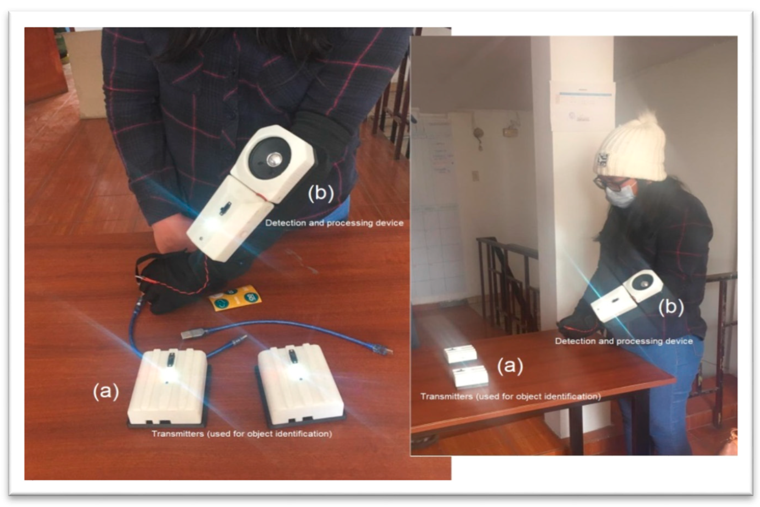
Figure 8.
Smart Glove. (a) Transmitters are used for object identification. Each transmitter stores the identification code of an object in the environment and transmits it to the glove (receiver) for its decoding and presentation to the DP (audio format). (b) The receiving device receives information from the transmitters, fetches it from the database, and presents it to the DP in audio format.

Figure 9.
Smart Glove—internal structure.

Figure 10.
Smart Cap—internal structure. (a) Example of mounting the device for the Smart Cap; (b) Internal view of the Smart Cap.
Figure 10.
Smart Cap—internal structure. (a) Example of mounting the device for the Smart Cap; (b) Internal view of the Smart Cap.

Figure 11.
Effectiveness vs. distance for each color detected.

Figure 12.
Smart Cap—fall control—analysis of angles.


Table 1.
Applications overview.
| Disability | Application | Sensors | Function | Platform | Technology | Reference |
|---|---|---|---|---|---|---|
| Visual | Object Identification | Accelerometer Gyroscope | Object recognition and navigation (Indoor) | Not Specified | Wearable | [11] |
| Visual | Object Identification | Camera module Ultrasonic | Identification of objects using markers (Indoor) | Embedded | Wearable | [12] |
| Visual | Navigation (Indoor) | GPS (Smartphone) | Indoor navigation | Mobile | Machine Learning | [13] |
| Visual | Menu Selection | Accelerometer (Smartphone) | Menu selection in mobile device applications | Mobile | Motion Marking Menus | [14] |
| Visual | Navigation | Camera module/Microphone, Speaker (Smartphone) | Object navigation, recognition and detection | Cloud and Mobile | Cloud (micro-services) and Image Recognition | [15] |
| Visual | Navigation | Ultrasonic, vibration motors, IR Sensor | Navigation in indoor environments | Not Specified | Wearable | [16] |
| Visual | Object Identification | 3D Printing | Tactile maps for objects identification | 3D Printing | [17] | |
| Visual | Navigation (Smart Cane) | Ultrasonic, Gyroscope and Smartphone | Smart Cane guided navigation integrated with a mobile API | Embedded and Mobile | IoT | [18] |
| Visual | Navigation (Smart Cane) | IR Sensor, GPS, Ultrasonic, Camera module, buzzer, raspberry | Navigation, identification of obstacles, objects and events | Embedded | IoT and Image Recognition | [19] |
| Visual | Navigation (Smart Cane) | Ultrasonic, Speaker, Camera module, raspberry. | Navigation, obstacle identification and voice alerts | Embedded | IoT | [20] |
| Visual | Navigation (Smart Cane) | Ultrasonic, Speaker, vibration motors, GSM | Navigation, obstacle identification, voice alerts and GSM | Embedded | IoT | [21] |
| Visual | Navigation (Smart Cane) | GPS and Speaker | Navigation, and buildings location | Embedded | IoT | [22] |
| Visual | Navigation (Smart Cane) | Ultrasonic, Humidity sensor, LDR sensor. | Navigation, obstacle identification. | Embedded | IoT and Image Recognition | [23] |
| Visual | Navigation (Smart Cane) | Laser, Camera module, GPS, speaker | Navigation, obstacle identification | Embedded | IoT | [24] |
Table 2.
Electronic components of the Smart Cane.
| Qty. | Description | Qty. | Description |
|---|---|---|---|
| 01 | 18650 Lithium Battery Charger | 01 | Mini vibration motor |
| 01 | TP4056 battery charger module | 01 | A9G Module (GSM/GPRS/GPS) |
| 01 | MT3608 Step-Up Adjustable DC-DC Switching Boost Converter | 01 | ESP32 Module |
| 01 | HC-SR04 ultrasonic sensor | 01 | Power Button for A9G |
| 01 | MPU-6050 sensor module | 01 | Speaker (8W) |
| 01 | PAM8403 Audio Amplifier Module | 01 | Push Button Switch |
| 01 | APDS-9960 Module Sensor (RGBC) | 01 | Led Power supply |
Table 3.
Electronic Components of the Smart Glove.
| Qty. | Receiver Module Components | Qty. | Transmitter Module Components |
|---|---|---|---|
| 01 | PAM 8403 Audio amplifier | 01 | Arduino nano |
| 01 | LM 339.4 analog comparators | 01 | Power Led |
| 01 | Nano Arduino | 01 | TCRT500 emitting infrared led |
| 01 | Power Led | 01 | Li-ion 18,650 battery |
| 01 | TCRT500 photo-transistor | 01 | TP4056 battery charger |
| 01 | Cell phone Li-ion battery | 01 | Charge/discharge switch |
| 01 | Charge/discharge switch | 01 | MT 3608 converter module DC-DC |
| 01 | TP4056 battery charger | ||
| 01 | MT 3608 converter module DC-DC |
Table 4.
Electronic Components of the Smart Cap.
| Qty. | Description | Qty. | Description |
|---|---|---|---|
| 01 | 18,650 Lithium battery | 01 | Buzzer |
| 01 | GUVA S12—UV sensor | 01 | A9G Module (GSM/GPRS/GPS) |
| 01 | ADXL 335—Accelerometer | 01 | Power button for the A9G |
| 01 | Start/load switch | 01 | LED power supply |
| 01 | Arduino Nano | 01 | MT3608 |
| 01 | TP4056 (Li-Ion Battery Charger) | 01 | HC-SR04 ultrasonic sensor |
| 01 | Buzzer | 01 | Mini vibration motor |
Table 5.
Range of sensors and accuracy of color identification (Smart Cane).
| Summary Table: Effectiveness (%) | |||||||||
|---|---|---|---|---|---|---|---|---|---|
| Distance (cm) | |||||||||
| Color Line | 1 | 2 | 3 | 4 | 5 | 6 | 7 | 8 | 9 |
| Red | 16.67 | 53.33 | 86.67 | 96.67 | 100.00 | 96.67 | 93.33 | 83.33 | 80.00 |
| Green | 6.67 | 50.00 | 83.33 | 100.00 | 100.00 | 93.33 | 93.33 | 86.67 | 83.33 |
| Blue | 10.00 | 36.67 | 83.33 | 96.67 | 100.00 | 100.00 | 93.33 | 86.67 | 76.67 |
| Black | 6.67 | 30.00 | 80.00 | 93.33 | 100.00 | 100.00 | 90.00 | 86.67 | 73.33 |
Table 6.
Error distance detection (obstacles).
| Distance Object (cm) | Measured Distance | Error (%) |
|---|---|---|
| 50 | 49.8 | 0.40 |
| 100 | 101.50 | 1.50 |
| 150 | 152.30 | 1.53 |
| 200 | 203.20 | 1.60 |
| 250 | 249.70 | 0.12 |
| 300 | 307.00 | 2.33 |
| 350 | 369.00 | 5.43 |
| 400 | 320.00 | 20.00 |
| 450 | 325.00 | 27.78 |
Table 7.
Range and accuracy of the receiver and transmitter modules—Smart Glove.
| D (cm) | T 1 (s) | T 2 (s) | T 3 (s) | T 4 (s) | T 5 (s) | T 6 (s) | T 7 (s) | T 8 (s) | T 9 (s) | T 10 (s) | Average |
|---|---|---|---|---|---|---|---|---|---|---|---|
| 1 | 1.4 | 2.8 | 2.32 | 2.22 | 2.72 | 1.68 | 2.6 | 2.2 | 1.68 | 2.85 | 2.247 |
| 2 | 1.88 | 2.13 | 2.28 | 2.55 | 2.83 | 2.28 | 3.01 | 1.95 | 2.12 | 1.98 | 2.301 |
| 3 | 2.35 | 2.18 | 1.82 | 2.08 | 2.48 | 2.08 | 2.78 | 2.58 | 2.47 | 1.64 | 2.246 |
| 4 | 1.95 | 2.26 | 2.1 | 1.52 | 2.55 | 2.15 | 2.18 | 2.52 | 2.78 | 2.68 | 2.269 |
| 5 | 3.02 | 2.58 | 1.95 | 2.65 | 2.68 | 2.24 | 2.9 | 2.93 | 2.6 | 2.8 | 2.635 |
| 6 | 2.48 | 3.5 | 3.12 | 3.08 | 3.1 | 2.57 | 2.8 | 2.95 | 2.2 | 2.5 | 2.83 |
| 7 | 2.37 | 1.99 | 2.31 | 3.21 | 2.55 | 2.95 | 2.25 | 2.68 | 2.81 | 2.88 | 2.6 |
| 8 | 2.27 | 3.12 | 2.67 | 3.13 | 1.85 | 2.88 | 2.58 | 3.14 | 2.05 | 2.82 | 2.651 |
| 9 | 1.97 | 2.18 | 2.37 | 2.86 | 3.63 | 2.4 | 3.2 | 3.22 | 2.92 | 2.58 | 2.733 |
| 10 | 2.52 | 2.49 | 2.23 | 2.42 | 4.23 | 3.72 | 2.82 | 2.33 | 2.42 | 2.6 | 2.778 |
Table 8.
UV function experiments.
| UV MAX | |||
|---|---|---|---|
| Expected Value | 12 | ||
| N° | Index | N° | Index |
| 1 | 8 | 11 | 8 |
| 2 | 8 | 12 | 7 |
| 3 | 7 | 13 | 9 |
| 4 | 8 | 14 | 8 |
| 5 | 9 | 15 | 9 |
| 6 | 9 | 16 | 9 |
| 7 | 8 | 17 | 8 |
| 8 | 8 | 18 | 9 |
| 9 | 8 | 19 | 8 |
| 10 | 8 | 20 | 8 |
| Average | 8.2 | ||
Table 9.
Usability experiments.
| Disabled Person | Devices | A | B | C | D | E | F | G |
|---|---|---|---|---|---|---|---|---|
| DP-1 | Smart Cane | 3 | 5 min | 100% | 2 | 30 min | 100% | High |
| Smart Cap | 4 | 10 min | 90% | 1 | 30 min | 100% | High | |
| Smart Glove | 1 | 5 min | 100% | 0 | 20 min | 80% | Low | |
| DP-2 | Smart Cane | 3 | 10 min | 80% | 4 | 30 min | 100% | High |
| Smart Cap | 4 | 10 min | 80% | 2 | 30 min | 90% | Low | |
| Smart Glove | 1 | 10 min | 100% | 0 | 20 min | 100% | High |
Publisher’s Note: MDPI stays neutral with regard to jurisdictional claims in published maps and institutional affiliations. |
© 2021 by the authors. Licensee MDPI, Basel, Switzerland. This article is an open access article distributed under the terms and conditions of the Creative Commons Attribution (CC BY) license (https://creativecommons.org/licenses/by/4.0/).
Share and Cite
MDPI and ACS Style
Beingolea, J.R.; Zea-Vargas, M.A.; Huallpa, R.; Vilca, X.; Bolivar, R.; Rendulich, J. Assistive Devices: Technology Development for the Visually Impaired. Designs 2021, 5, 75. https://0-doi-org.brum.beds.ac.uk/10.3390/designs5040075
AMA Style
Beingolea JR, Zea-Vargas MA, Huallpa R, Vilca X, Bolivar R, Rendulich J. Assistive Devices: Technology Development for the Visually Impaired. Designs. 2021; 5(4):75. https://0-doi-org.brum.beds.ac.uk/10.3390/designs5040075
Chicago/Turabian StyleBeingolea, Jorge Rodolfo, Miguel A. Zea-Vargas, Renato Huallpa, Xiomara Vilca, Renzo Bolivar, and Jorge Rendulich. 2021. "Assistive Devices: Technology Development for the Visually Impaired" Designs 5, no. 4: 75. https://0-doi-org.brum.beds.ac.uk/10.3390/designs5040075