1. Introduction
The United States spends annually over a billion dollars on bridge maintenance and their damage control [
1,
2]. The damages mainly result from corrosion chloride attack on substructure elements such as columns [
1,
2], and the repair procedure of such elements usually involves removal of the damaged substrate and recasting the damaged zone with new material.
The recast can change the material properties and/or the geometry of the section, which will affect the mechanical behavior of the substructure. With the advances made in the production of concrete mixes with much higher mechanical strength compared to the conventional concrete, the application of such high-performance materials for repair application is becoming more common. The considerable difference in the mechanical properties of the repair and substrate material changes the sectional properties and leads to a more significant effect on mechanical behavior.
A method has been proposed for repairing reinforced concrete elements using ultra high-performance concrete (UHPC) to enhance the mechanical strength of the structure [
3,
4,
5]. This method replaces the damaged surface concrete with a UHPC shell encapsulation [
3,
4,
5]. The experimental investigation of the retrofitted columns with UHPC showed that this repair method is rather efficient regarding lateral strength, deformation, energy dissipation capacity, and stiffness degradation [
3,
4,
5]. Furthermore, the results indicated that depending on the UHPC shell thickness and due to its much higher strength compared to substrate material, the capacity of the repaired section could significantly increase and become stronger than the original designed section. Therefore, repairing the critical section (or plastic hinge location) of a column will significantly change the behavior of the structure. This change in the sectional properties of the repaired portion of the column may cause the critical section (or plastic hinge) to relocate to adjacent unrepaired sections or footing/cap-beam. This relocation could put protected members such as footings and cap-beams at risk, which should be avoided. Therefore, sectional changes due to repair should be investigated carefully in the design stage.
Typically, a reinforced concrete bridge column has a circular cross-section, with a circular distribution of reinforcements, which makes the sectional analysis more complicated, to a point that it requires using design software (such as SAP2000) to obtain the new sectional properties. The successful implementation of such an approach inherently depends on the availability of the stress-strain curves for the substrate and repair materials. The analytical solutions available in the literature to calculate the moment capacity of beam sections after repair are limited to rectangular cross-section [
6,
7]. To date, there has been no research proposing a simplified method to calculate the sectional properties (bending moment capacity) of circular columns repaired with a layer of UHPC.
In this communication, a simplified approach to calculate the sectional properties of the repaired circular section is proposed. This method requires only the basic material properties (compressive and tensile strength) and works well even without having access to the material stress-strain curve. Furthermore, the proposed method mostly relies on hand calculations, which provides the opportunity to easily implement this method at the repair design stage. Therefore, the proposed tactic can be considered simple and more straightforward for professional engineers.
2. Solution Derivation
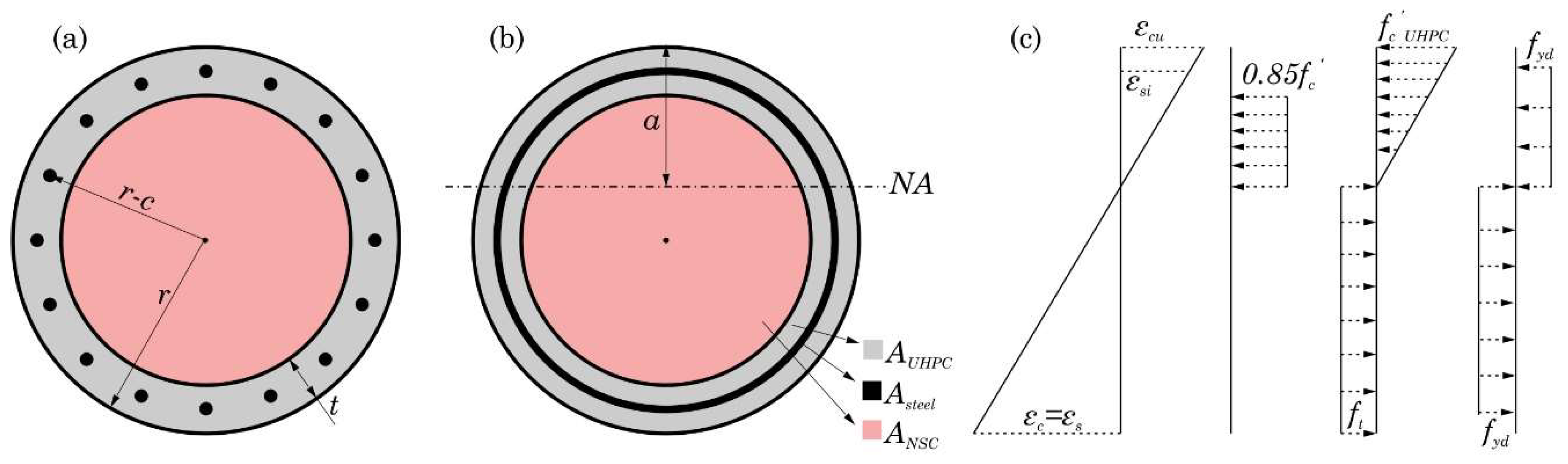
The presented method was derived to calculate the moment capacity of a circular reinforced normal strength concrete (NSC) column repaired with UHPC. It was assumed that the repair material (UHPC) has a perfect bond with substrate concrete and act composite in the section.
Figure 1a shows a typical section of a repaired column, where the column radius is
, the repair thickness (UHPC shell thickness) is
, the structural concrete cover is
, and the column is under axial load (
).
The first step in calculating the moment capacity of the repaired section is to obtain the location of the neutral axis (NA). The depth of the NA (
) was found using force equilibrium in the section, Equation (1). There are four types of axial forces acting on the section: (1) tensile and compressive force in NSC (
), (2) tensile and compressive forces in UHPC (
), (3) tensile and compressive forces in steel reinforcement (
), and (4) external axial force (
).
The terms on the left-hand side of Equation (1) represent all the internal axial forces in the column section.
To find the contribution of each material (UHPC, steel, NSC) to the internal forces, one should use their stress-strain diagrams to relate the flexural deformations to the internal forces. However, the stress-strain diagram of each material is not always readily available. To overcome this limitation, a solution is proposed using only basic material properties. The material behavior is simplified with reasonable assumptions. Rigid–ideally plastic material behavior was assumed for reinforcing steel. The flexural behavior of NSC was simplified using a rectangular stress block [
8]. On the other hand, a linear stress distribution was assumed for UHPC, due to the higher compressive strength, instead of a constant stress block [
9,
10,
11,
12]. The tensile stresses in NSC can be ignored [
8]; however, tensile stresses in UHPC should be considered, due to its higher ductility and tensile strength. The tensile stresses in UHPC were assumed to have a constant distribution [
12,
13,
14,
15].
Under these assumptions, if the section is loaded above its moment capacity, it will fail due to concrete crushing. Any strain distribution in the section conforming to such mode of failure should have its fixed point at the limit value of maximum concrete compressive strain (
) [
16]. Such strain distribution was used to model the section’s behavior,
Figure 1.
Following the scheme presented by Cosenza et al. [
17] (to calculate the bending moment capacity of circular RC cross-sections subjected to axial loads combined with uniaxial bending), all of the steel reinforcements are merged into an equivalent steel ring, with the total area of
As.
Figure 1b,c show the simplified repaired section, the unknown location of the NA, the corresponding strain diagram, and the assumed stress distributions in NSC, UHPC, and reinforcements.
is the design value of concrete compressive strength (0.85
), and
a is the distance of the NA from the top of the section.
is the nominal 28-day compressive strength of UHPC, and
is the tensile strength of UHPC.
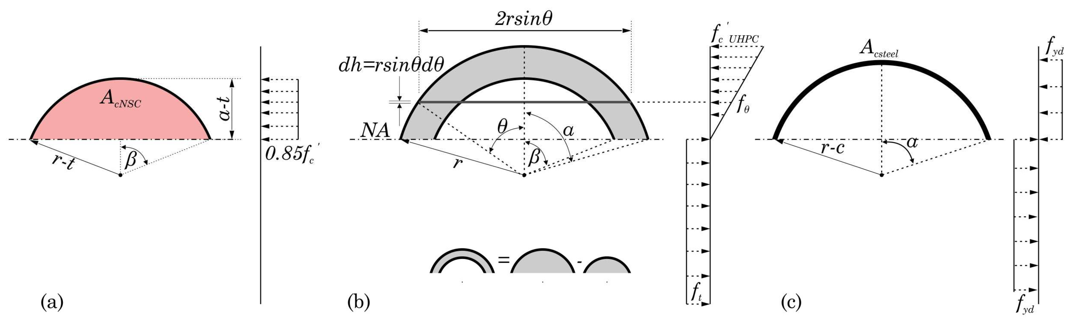
The internal axial forces shown in Equation (1) can be calculated by integrating each stress distribution over the area of corresponding material in the section (
Figure 2).
2.1. NSC
The compressive axial force in NSC is equal to the integral of the constant stress block over the circle segment shown in
Figure 2a. Since the stress is assumed to be constant, the integral would be equal to the product of the area and the stress magnitude, Equation (2).
The tensile axial force in NSC is assumed to be zero, .
2.2. UHPC
The compressive force in UHPC, Equation (3), is equal to the integral of the linear stress distribution over the shell segment shown in
Figure 2b.
is one half of the angle subtended at the center of the cross-section by the UHPC compression sector, and
is one half of the angle subtended at the center of the cross-section by the concrete compression sector (
Figure 2b).
where:
Substituting Equation (4) back into Equation (3):
The tensile force in UHPC can be calculated by integrating the tensile stress in UHPC over its corresponding area. Since the tensile stress in UHPC is assumed to be constant (see
Figure 2b), we can approximate the integral by Equation (6).
2.3. Reinforcement
Considering that the reinforcements are merged into an equivalent steel ring, the area of longitudinal reinforcements in compression and tension will respectively be
, and
(
Figure 2c). Accordingly, the axial compressive and tensile forces in the reinforcements could be approximated as:
2.4. Force Equilibrium
Substituting Equations (2), (5)–(7), and (8) back into Equation (1) will result in:
For a given section, finding the location of NA is the same as finding the values of
and
that satisfies Equation (9). Considering that the angles
and
are related by:
Equation (9) could be rewritten in terms of only one unknown and solved by any numerical root finding technique. It should be noted that for deriving Equation (9), the initial assumption is
(see
Figure 2). If the calculated
is less than the UHPC thickness, then the whole NSC section would be in tension. As mentioned earlier NSC does not contribute to the tensile forces; therefore, when
, Equation (9) should be modified to reflect this:
2.5. Moment Capacity
The moment capacity of the section (
MRd) could be calculated by summing the moments of each force about the NA.
where
,
,
,
, and
are the moments due to compression in NSC, compression in UHPC, the tension in UHPC, compression in steel reinforcement, and tension in steel reinforcement, respectively. The parameters on the right-hand side of Equation (12) are defined as:
Equations (13)–(16) are valid when
. If the obtained value for
is smaller than
, then the NSC is in tension and it will not produce any moment. Equation (14) should be presented as:
and Equation (13) will be simplified to:
To make the equation more simplified, the same process was performed except rectangular stress distribution was considered, instead of the triangular one, for UHPC. “” is the reduction factor of the compressive strength of UHPC.
The compressive force of the UHPC shell is then calculated by integration over the shell length on the compression side (Equation (19)).
The force component of the remaining sections follows the previous equations. The determination of the location of the neutral axis was again carried out by iteration methods with the initial assumption of
(Equation (20)).
If the calculated
does not meet the initial assumption, it should be calculated using Equation (21).
The member flexural capacity of the UHPC in compression (
) is then determined by Equation (22) for the initial assumption of
.
and if
,
is calculated by Equation (23).
The reduction factor for the compressive strength of UHPC was determined by equating the results calculated through both stress distributions. It was observed that
varies when
varies. This relationship was estimated by Equation (24).
3. Illustrative Example
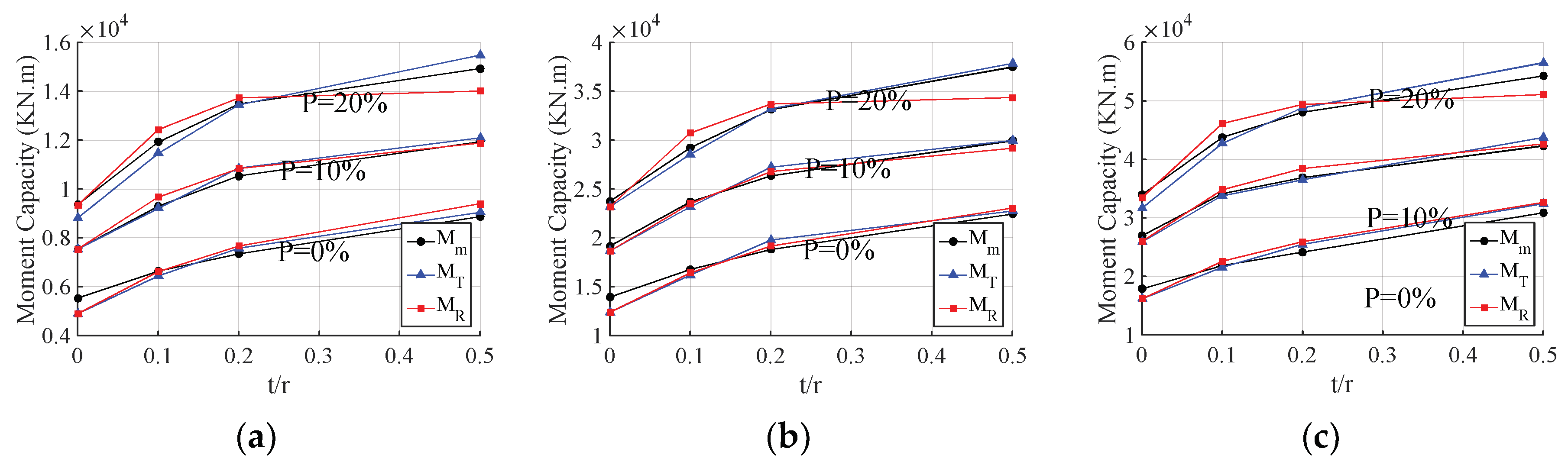
In this section, the proposed method is examined against the well-known moment-curvature method. Three sets of numerical experiments are designed using three common sizes of prototype columns (r = 686, 914, 1067 mm). Each set is repaired with three different UHPC shell thicknesses (t/r = 0.1, 0.2, 0.5) and loaded with three different axial loads (P = 0%, 10%, 20%). The moment capacity for each repair configuration is obtained using the proposed simplified method and compared with the moment-curvature data. For both methods, substrate concrete, UHPC, and steel are characterized by , , and , respectively.
The moment-curvature method uses the constitutive model proposed by Mander et al. [
18] for the confined and unconfined concrete. The required stress-strain data for UHPC is based on the experiments presented in References [
12,
19], and the stress-strain relation for reinforcing steel is defined according to Park et al. [
20].
To obtain a numerical solution for the moment-curvature method, the moment capacity of the section is calculated for increasing levels of curvature, and the location of the neutral access is determined for each level of curvature using an iterative method.
This method stops when the concrete strain in the core exceeds the maximum concrete compressive strain, or the tensile strain in the steel bars surpasses the maximum steel strain. The nominal moment capacity (
) is then determined by balancing the area between the actual and idealized (elastic-plastic) moment-curvature curve beyond the first reinforcing bar yield point [
21].
Figure 3 shows the values of bending moment capacity of the three prototype circular cross-section columns under different axial load level and with different shell thicknesses.
is the value of the flexural capacity of cross-section computed by the moment-curvature analysis.
and
are the value of the flexural capacity of cross-section calculated by the proposed method when the stress distribution for UHPC in compression is triangular and rectangular, respectively.
Figure 3 reveals that the design value of load carrying capacity of eccentrically compressed RC members of circular cross-section determined by the proposed method for both triangular and rectangular stress distribution for UHPC in compression is very close to that determined using more refined methods of analysis.
The comparison shows that the average ratio between design load carrying capacity of eccentrically compressed RC members of circular cross-section determined by the proposed method with triangular stress distribution of UHPC in compression (), and the moment-curvature ones () is 0.98 with a maximum value of . These values for the rectangular stress distribution of UHPC in compression () are 0.99 and 1.07 for the average and maximum values, respectively. The results show that the method is very well-suited for smaller thicknesses of UHPC and axial load level of 10%, which is a common condition for bridge substructures.
4. Conclusions
In this study, simple formulae were proposed to analyze the bending moment capacity of circular cross-sections, repaired with an outer layer of UHPC, subjected to axial loads. Since this method requires only the basic material properties (compressive and tensile strength) and mostly relies on hand calculations, it can be easily implemented at the repair design stage.
A thorough numerical experiment has been performed to determine the level of precision of the proposed method. The results obtained for a wide range of design cases (corresponding to the most commonly employed in practice) have shown a very good resemblance of the values computed by moment-curvature analysis, especially for axial load levels similar to common existing bridge column conditions. This approach can be taken advantage of by professionals to quantify the strengthening of circular columns when repaired with a UHPC layer.
Author Contributions
Conceptualization, M.F., S.R., A.S. and A.A.; methodology, M.F. and S.R.; software, M.F., S.R. and A.S.; validation, M.F., S.R. and A.S.; formal analysis, S.R.; investigation, M.F., S.R., A.S. and A.A.; writing—original draft preparation, M.F. and S.R.; writing—review and editing, M.F., S.R., A.S., and A.A.; visualization, S.R.; supervision, A.A.; project administration, M.F.
Funding
This research was funded by U.S. Department of Transportation, grant number DTRT13-G-UTC41 through Accelerated Bridge Construction University Transportation Center (ABC-UTC) with Florida International University (Lead), Iowa State University, and the University of Nevada, Reno.
Acknowledgments
This paper reflects the views of the authors and not necessarily of the funding agency.
Conflicts of Interest
The authors declare no conflict of interest.
References
- American Society of Civil Engineers. Asce 2017 Report Card for America’s Infrastructure; American Society of Civil Engineers ASCE: Reston, VA, USA, 2017. [Google Scholar]
- Lampo, R.; Maher, A.; Busel, J.; Odello, R. Design and development of FRP composite piling systems. Plast. Build. Constr. 1997, 21, 9. [Google Scholar]
- Farzad, M.; Azizinamini, A. Accelerated Retrofit of Bridge Columns Using UHPC Shell—Phase I: Feasibility Study; Final Report, ABC-UTC; Florida International University: University Park, FL, USA, 2018. [Google Scholar]
- Farzad, M.; Shafieifar, M.; Azizinamini, A. Accelerated Retrofitting of Bridge Elements Subjected to Predominantly Axial Load Using UHPC Shell. In Proceedings of the Transportation Research Board 97th Annual Meeting Transportation Research Board, Washington, DC, USA, 7–11 January 2018. [Google Scholar]
- Farzad, M.; Shafieifar, M.; Azizinamini, A. Retrofitting of Bridge Columns Using UHPC. J. Bridg. Eng. 2019, in press. [Google Scholar]
- Zhang, Y.; Zhu, Y.; Yeseta, M.; Meng, D.; Shao, X.; Dang, Q.; Chen, G. Flexural behaviors and capacity prediction on damaged reinforcement concrete (RC) bridge deck strengthened by ultra-high performance concrete (UHPC) layer. Constr. Build. Mater. 2019, 215, 347–359. [Google Scholar] [CrossRef]
- Chalioris, C.E.; Thermou, G.E.; Pantazopoulou, S.J. Behaviour of rehabilitated RC beams with self-compacting concrete jacketing—Analytical model and test results. Constr. Build. Mater. 2014, 55, 257–273. [Google Scholar] [CrossRef]
- American Concrete Institute. ACI Manual of Concrete Practice; American Concrete Institute: Farmington Hills, MI, USA, 1968. [Google Scholar]
- Bae, B.-I.; Choi, H.-K.; Choi, C.-S. Flexural Strength Evaluation of Reinforced Concrete Members with Ultra High Performance Concrete. Adv. Mater. Sci. Eng. 2016, 2016, 1–10. [Google Scholar] [CrossRef] [Green Version]
- Shafieifar, M.; Farzad, M.; Azizinamini, A. A comparison of existing analytical methods to predict the flexural capacity of Ultra High Performance Concrete (UHPC) beams. Constr. Build. Mater. 2018, 172, 10–18. [Google Scholar] [CrossRef]
- Yoo, D.Y.; Yoon, Y.S. Structural performance of ultra-high-performance concrete beams with different steel fibers. Eng. Struct. 2015, 102, 409–423. [Google Scholar] [CrossRef]
- Aaleti, S.; Petersen, B.; Sritharan, S.; Bradley, P.; Sritharan, S. Design Guide for Precast UHPC Waffle Deck Panel System, Including Connections; No. FHWA-HIF-13-032; Federal Highway Administration: Washington, DC, USA, 2013.
- American Concrete Institute (ACI) Committee 318. Building Code Requirements for Structural Concrete (ACI 318-14); American Concrete Institute (ACI) Committee 318: Farmington Hills, MI, USA, 2014; ISBN 9780870312649. [Google Scholar]
- American Concrete Institute (ACI) Committee 544. Design Considerations for Steel Fiber Reinforced Concrete, ACI 544; American Concrete Institute: Farmington Hills, MI, USA, 1994. [Google Scholar]
- Steinberg, E. Structural Reliability of Prestressed UHPC Flexure Models for Bridge Girders. J. Bridg. Eng. 2010, 15, 65–72. [Google Scholar] [CrossRef]
- De Normalisation; Comité Européen. Eurocode 2: Design of Concrete Structures—Part 1-1: General Rules and Rules for Buildings; European Commitiee for Standardization: Brussels, Beligum, 2004. [Google Scholar]
- Cosenza, E.; Galasso, C.; Maddaloni, G. Simplified Assessment of Bending Moment Capacity for Rc Members with Circular Cross-Section. In Third International Fib Congress and Exhibition & PCI Annual Convention and Bridge Conference; Precast/Prestressed Concrete Institute: Chicago, IL, USA, 2010; pp. 1–11. [Google Scholar]
- Mander, J.B.; Priestley, M.J.; Park, R. Theoretical stress-strain model for confined concrete. J. Struct. Eng. 1988, 114, 1804–1826. [Google Scholar] [CrossRef]
- Shafieifar, M.; Farzad, M.; Azizinamini, A. Experimental and numerical study on mechanical properties of Ultra High Performance Concrete (UHPC). Constr. Build. Mater. 2017, 156, 402–411. [Google Scholar] [CrossRef]
- Park, R.; Paulay, T. Reinforced Concrete Structures; J. Wiley & Sons: Hoboken, NJ, USA, 1975; ISBN 9780471659174. [Google Scholar]
- Caltrans (California Department of Transportation). Caltrans Seismic Design Criteria; version 1.7; California Department of Transportation: Sacramento, CA, USA, 2013.
© 2019 by the authors. Licensee MDPI, Basel, Switzerland. This article is an open access article distributed under the terms and conditions of the Creative Commons Attribution (CC BY) license (http://creativecommons.org/licenses/by/4.0/).

