Integration of BIM and Procedural Modeling Tools for Road Design
by
 ,
,
Salvatore Antonio Biancardo
1,* ,
,
Alessandra Capano
1, 
Sara Guerra de Oliveira
1 and
Andrej Tibaut
2
1
Department of Civil, Construction and Environmental Engineering, Federico II University of Naples, 80125 Naples, Italy
2
Faculty of Civil Engineering, Transportation Engineering and Architecture, University of Maribor, 2000 Maribor, Slovenia
*
Author to whom correspondence should be addressed.
Infrastructures 2020, 5(4), 37; https://0-doi-org.brum.beds.ac.uk/10.3390/infrastructures5040037
Submission received: 15 March 2020
/
Revised: 15 April 2020
/
Accepted: 18 April 2020
/
Published: 20 April 2020
(This article belongs to the Special Issue Smart Cities and Infrastructures)
Abstract
:Building Information Modeling (BIM) is a design and management methodology strongly used in the Industry of Architecture, Engineering, and Construction (AEC). It allows the creation of a 3D model through parametric modelling in a workflow that updates data, geometry and semantics using the Industry Foundation Classes (IFC) standard. The purpose of this paper is to develop and apply a BIM method for road infrastructures. The creation of the BIM 3D models was carried out using different visual programming software and BIM tools, designing the spatial and parametric representation of the roadway. This way, it has been possible to discover the advantages of using procedural modelling to design road infrastructure through software that are usually used in the mechanical and architectural field. Finally, the interoperability of the software to extract and exchange information between these BIM tools was assessed.
1. Introduction
A smart city involves urban development aimed at improving the quality of life of citizens by optimizing the operation and management of infrastructure systems [1] due to the integration of information and communication technologies [2].
In this context, a smart infrastructure is developed through the combination of physical and digital infrastructures, providing more information to improve management decisions [3].
As a result, in the age of the Internet-of-Things and Big Data, Building Information Modeling (BIM) becomes a necessity for the planning and management of smart cities [4]. They are starting to be integrated into the architecture, engineering and construction (AEC) industry for infrastructure design [1].
BIM has shown great value in providing solutions to the problems posed by the construction industry [5]. At present, there is a tendency to improve the AEC industry worldwide, to the extent that BIM is being expanded into sectors for which it was not originally designed, such as the infrastructure sector, the implementation of which has posed new challenges [6]. Indeed, the limited availability of libraries of infrastructure components and the difficulty in assigning parameters to object geometries are considered the main obstacles to the use of BIM for transport infrastructure [7].
To guide the geometric modeling process in the context of BIM, visual programming languages (VPL) are becoming increasingly important. Developed since the 1950s, these programming languages are based on graphs defined by nodes and connections, which represent the programming logic. Using the graphs and tuning the input parameters, the geometry model is designed.
Currently, there are visual scripting components for the main BIM software available, such as the Dynamo for Autodesk Revit, Rhinoceros with Grasshoper for ArchiCAD, and Generative Components for the Bentley platform [8].
In addition, there is an extensive literature research developed to align the creation of construction models with civil transport assets divided into five categories such as bridges, roads, railways, tunnels and airports [7]. Of these, projects using the methodologies based on VPL programming and implementation codes are considered below.
As far as the airport category is concerned, the project for an international airport in Mexico City, expected to become one of the largest in the world, relied highly on BIM, which supported the achievement of the proposed set of objectives on sustainability and innovative terminal design. Sharing of infrastructure models built with Autodesk software has given all teams access to up-to-date information, enabling a smooth transition from the conceptual phase to a more detailed design and construction phase [12].
In the rail sector, BIM was used to design a new monorail in a Korean park using modeling and visual communication software for faster approval. The design started with Civil 3D to generate a 3D topographic model of the park and explore options for the monorail route through the park terrain. Subsequently, surfaces, alignments, profiles and corridors were created for the monorail track. From Civil 3D, the surface and profile information were extracted to an Excel spreadsheet, which was then used in Dynamo to model the curved surface of the track [13].
In Istanbul, a Municipality project involved the design of a 16 km metro line, consisting of 11 stations that will connect to five existing metro lines. The project plays a key role in Istanbul’s public transport system, presenting a logistical challenge involving different AEC disciplines. To address this challenge, software was used to define the design process and create a single integrated BIM platform [14].
Another element considered in the planning and execution of road and rail projects is the construction of embankments. To perform the calculations, the embankment cross-sections are transferred from the planning software to the geotechnical software and the results obtained are inserted in the Autocad-based design software with BIM capability. This software contains all relevant design information such as embankment geometry, surface geometry and soil stratification including material assignment. The geotechnical software is based on the Python programming language, which is useful for importing geometric and material information in an appropriate way [15].
Moreover, the potential of VPL and BIM has also been confirmed through a case study on soil safety planning and modelling in the pre-construction phase of the infrastructure. A set of algorithms has been developed using Grasshopper as VPL that automatically generates the geometric conditions in the BIM 3D model through interaction with Revit, visualizing the potential risks and installation of safety resources [16].
Regarding the category of bridges and tunnels, the design can be done through a new approach of Knowledge-Based Engineering (KBE), for which the infrastructure is modelled by exploring various options that lead to an optimal or almost optimal solution with regard to technical and economic aspects. In this way it is also possible to make the design semi-automated to save time and increase planning quality. Geometric-semantic modeling was carried out using VPL Dynamo [17].
Bridge models can also be obtained by following a workflow composed by the conceptual design of the road and the planned bridge using Infraworks 360. This model is then imported in Civil 3D to add details of the road design. The data is then entered in Revit and Dynamo to obtain the detailed project of the bridge. The process is highly automated, and this allows for the creation of different bridge alternatives quickly and effectively [18].
In the road category, an integrated BIM and life cycle assessment (LCA) model was created for the design of a motorway section in Norway. The model results showed that it is possible to combine LCA data into a BIM model using C# as a programming language in Microsoft Visual Studio to develop an Autodesk Civil 3D application and perform calculations [19].
Furthermore, based on Dynamo’s capabilities, through a case study of a highway in Cambodia, a 3D road model with controllable parameters for the pavement was established, then a Python-based sub-routine was developed to combine Dynamo with the software for the analysis of the pavement structure [20].
Moreover, in Asia, the most advanced countries in terms of the adoption of BIM are also focusing on the infrastructure sector [21]. In particular, China has taken an interest in both the construction of major road projects [9] and the design of municipal roads, combining traditional CAD 2D drawings with the BIM model to share digital design information [22].
The Yulin–Zhanjiang Expressway project includes a four-lane expressway with seven toll stations, two service areas and a parking area. The broad and multidisciplinary nature of the project suggested that 3D visualization was crucial for analysis of the spatial relationships of the different model parts [14].
In recent decades, the construction of motorway tunnels in China has been at an increasing pace, posing a challenge to facility management (FM), to ensure safe and reliable tunnel operation. The tunnel BIM model was developed with Revit software and then connected to the SQL database for FM requirements through the coding system. Every single element of the BIM model was enriched with FM information and presented for visualization. [23].
Lastly, it can be noted that in the USA, BIM is used on almost 50% of infrastructure projects [17] and Australia has achieved good results in terms of cost, time and quality of major road works [9].
Therefore, the results show that the use of BIM for infrastructure has increased, mainly for roads and highways [24], but engineering opinion may be required as these works often include more unknown factors than construction projects [17]. Indeed, large infrastructure projects are complex to model, as they require efficient information sharing [25].
A smart infrastructure for smart urban planning is difficult to achieve unless data is shared in an interoperable and coherent way between different infrastructure systems [1].
Standardization is needed to address these interoperability problems. Indeed, BIM aims to facilitate requirements through the Industry Foundation Classes (IFC), the standard that enables efficient storage, management, exchange and presentation of information. However, the current IFC version 4×2 provides classes that primarily support buildings and provides limited support for infrastructure elements. To incorporate this information, it is necessary to extend the desired entity to generalized classes that affect infrastructure objects not only geometrically but also semantically, making the introduction of Asset Management information difficult [25].
Interoperability is therefore not only a mere exchange of data, such as geometric characteristics, but also the exchange of meaning [26]. This is what allows BIM to go beyond the production of 3D models; it is not limited to the visualization of a modeled structure, but it also adds information [9].
To model a smart infrastructure, it is necessary to find a set of variables and parameters essential for the analysis and prediction of the performance of built objects [27]. Data modeling can be performed by procedural, also known as parametric, modeling that provides object-oriented n-dimensional information or generative model information containing objects created through algorithmic processes [26].
Parametric and procedural 3D geometrical models can be represented by graphs in order to define relationships and dependencies between geometric entities and allow its reuse in similar design scenarios or to adapt it to different scenarios [28].
The main objective of the proposed study is to build a road infrastructure using procedural modeling software and BIM software tools usually used in the mechanical and architectural field to test the modeling capability of a road infrastructure and interoperability in the exchange of information between BIM tools.
The paper focuses on the use of design software that allows 3D visualization and parameterization of road infrastructure through procedural modeling software, allowing greater flexibility in the implementation process. A parametrized procedural model for a road was developed. Finally, by adopting a BIM viewer, it was possible to evaluate the ability to extract and exchange information between these BIM software tools.
The advantages of using the BIM methodology for smart infrastructure design are highlighted, but also the limits must be taken into account for future development linked mainly to the designer’s skills.
2. Procedural Modeling of a Road Infrastructure
The case study conducted consists of the design of a section of a road infrastructure, supported by two design software that allow the visualization and parameterization of the model, implementing BIM software tools when there is compatibility between them.
The infrastructure was designed according to the Italian Standards, in particular:
- Italian geometric Standard [29], which defines the criteria for the design of the functional aspects and geometric elements of roads, in relation to their classification according to the Highway Code;
- Road Pavements Catalogue [30], which offers a range of road structure solutions of various types and valid for the typical traffic and environmental conditions;
- Regulations for the implementation of the Highway Code [31], taken as reference for horizontal road markings.
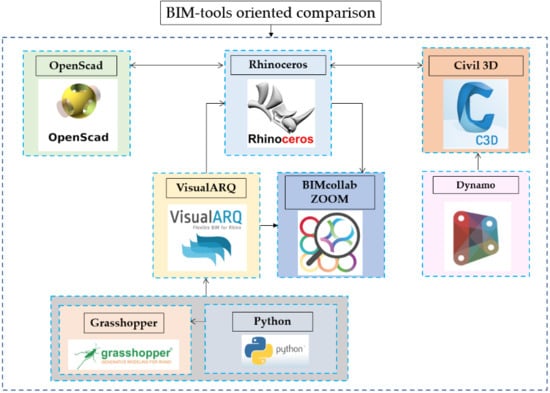
The description and comparison of the three different approaches for infrastructure modeling using OpenSCAD, Rhinoceros and Civil 3D software is outlined as follows.
In particular, with regard to the second software, the plug-ins, Grasshopper and VisualARQ are employed. Finally, for the visualization of the work another BIM software tool, BIMcollab ZOOM is used.
The third software Civil 3D is combined with the Dynamo plug-in.
2.1. Use Case: Road Infrastructure Design in OpenSCAD
The first software used for the infrastructure design is OpenSCAD, which can create complex solid CAD 3D models and is supported by an intuitive functional programming language.
The output of 3D solid is a result of the iterative and methodical implementation of the entire set of modules and parameters, which are subsequently used to create the output with respect to the reference legislative sources.
In particular, with regard to the above-mentioned parameters, two main variables have been defined, length and type of road, whose variation radically affects the output itself. Indeed, the type of road conditions the entire set of parameters attributed to the final model. This parameterization allows the designer to create multiple combinations between all the main distinctive features of the road infrastructure while still respecting the limits indicated.
The first lines of the code are shown in Figure 1. The full computer code is available as Supplementary Materials.
The individual elements, part of the road infrastructure, are built using custom script modules defined by the designer, in which different types of OpenSCAD commonly used actions and operators are specified.
The construction of the three-dimensional elements is organized in script modules, which define the layers of the road pavement. Therefore surface, binder, base, foundation layers, left and right quays and divider are sketched as cubes that can be moved into the correct position in order to match the road surface with the xy plane.
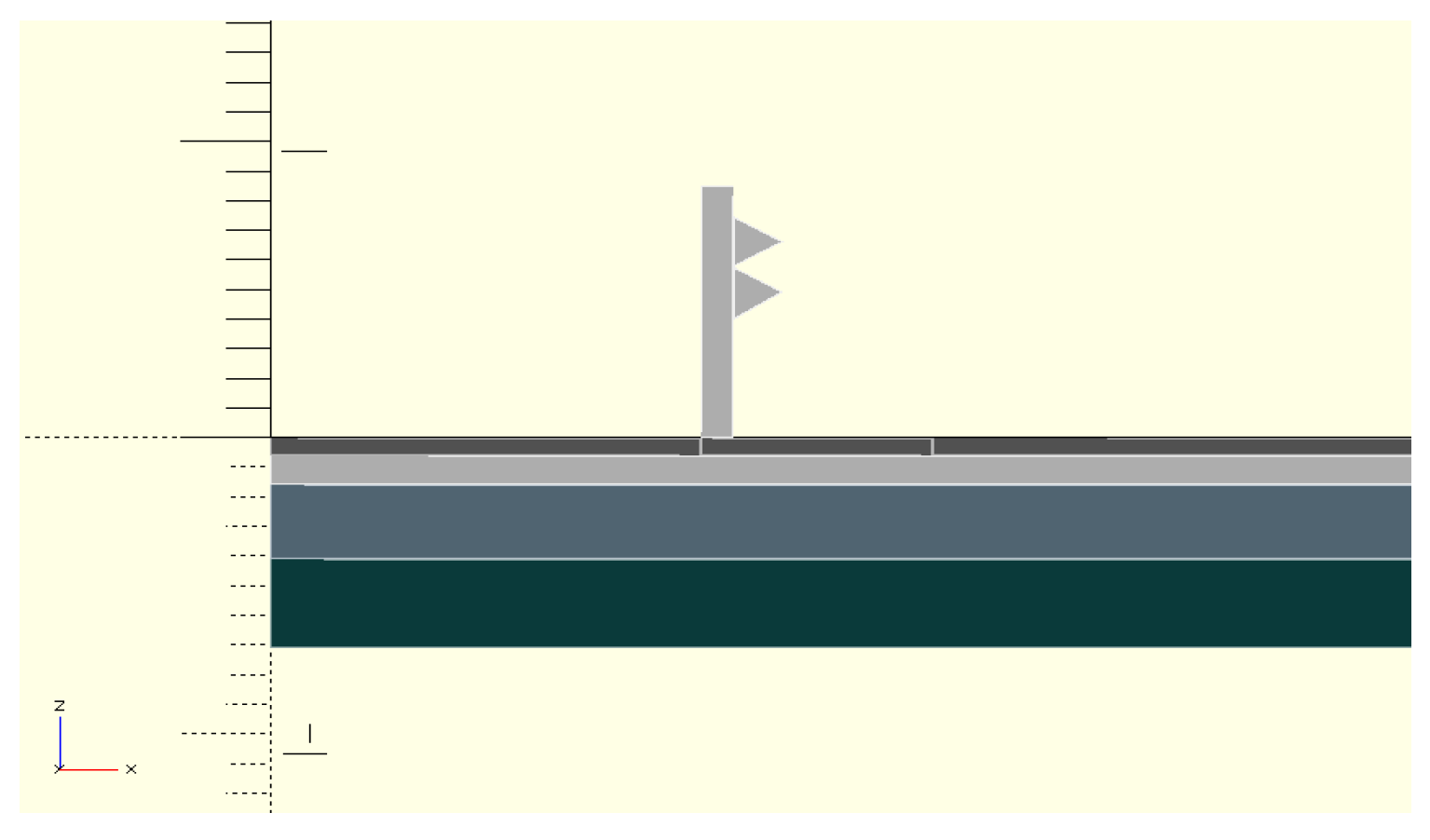
The guardrail is chosen as a road safety system and it consists of columns connected to each other by a simplified two-wave band. The polyline tool is used to build the section of the two-wave band on the left and right side of the road, as shown in Figure 2. As for the other element, also the barrier element makes use of different parameters such as width and height.
To complete the barrier construction, another module has been added, which allows to take into account that for some types of roads there is no divider and no safety system required, so the “if” statement comes handy to differentiate all the possible cases.
If this is not the case and the presence of a divider and guardrail is necessary, then the “else” statement is able to construct the safety system using the linear extrusion of the section of the barrier to bring the two-wave band along the whole length of the road.
The geometry of the guardrail column is defined with a cube and through a “for” loop, it is moved along the z-axis for the defined interval between the columns to the end of the road length.
Finally, the body of the guardrail is complete, positioned on both the left and the right roadside according to regulations.
To create the edge stripes on the left and right side, the geometry used is a cube, which is then translated along the x-axis to position it correctly.
The geometry of a single section belonging to the lane stripe is created using the cube command and it is then moved along the x-axis to position it between two lanes.
The “For” loop statement is executed in order to repeat the single segment of the stripe along the y-axis and to create a complete discontinuous stripe.
To make sure another longitudinal discontinuous stripe is to be displayed in case the road type has three lanes, an “if” statement has to be added into the stripes element.
All the objects previously described are grouped in a script module to assign to the road the correct cross slope according to the road design norms D.M. 05/11/01 [29].
Lastly, the other carriageway is constructed to complete the road structure.
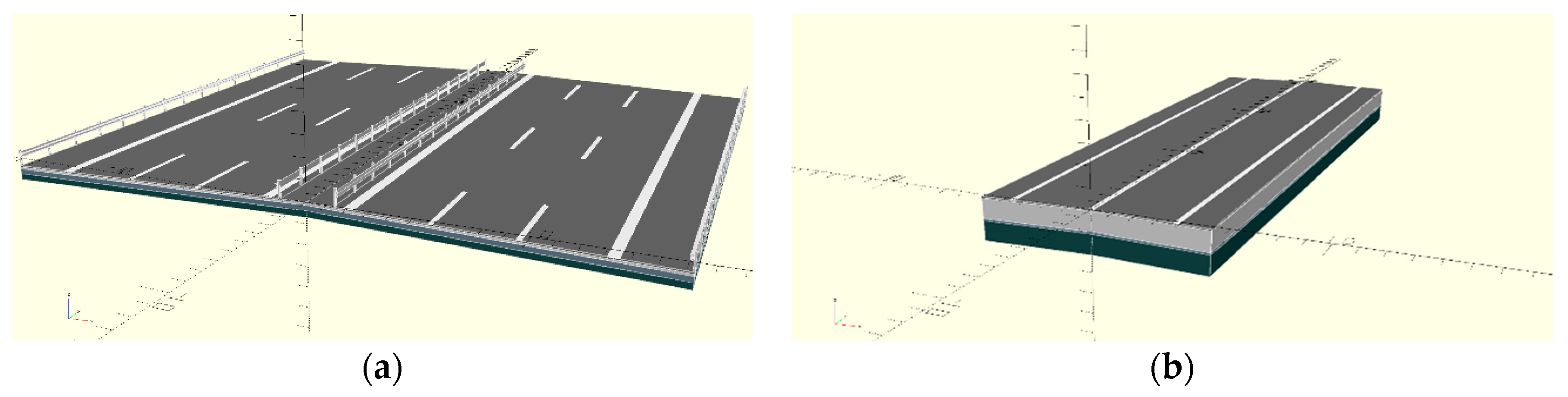
All the different types of road can be obtained simply by selecting a letter from a selection list as input to the “roadname” parameter, as shown in the Figure 3.
2.2. Use Case: Road Infrastructure Design in Rhinoceros and Grasshopper
Rhinoceros, widely applied in different fields, is the second software used for the case study, mainly due to its multidisciplinary functionality.
One of the benefits from the Rhinoceros usage is the implementation of the Grasshopper plug-in, a parametric modeling and visual programming tool that simplifies the modeling procedure by visually presenting the workflow in a flowchart display. It is based on the idea of “boxes and arrows”, indeed each Grasshopper component has input and output connectors, which means that the component processes the input data and returns it to the output.
Objects can be built either through the basic tools provided by the program or through the use of different supported programming languages, such as Python, C# and Visual Basic, which make the project very flexible and customizable. This is allowed especially on account of the parameterization of its objects.
Once the design algorithm is generated, it is possible to visualize the results in the Rhinoceros workspace.
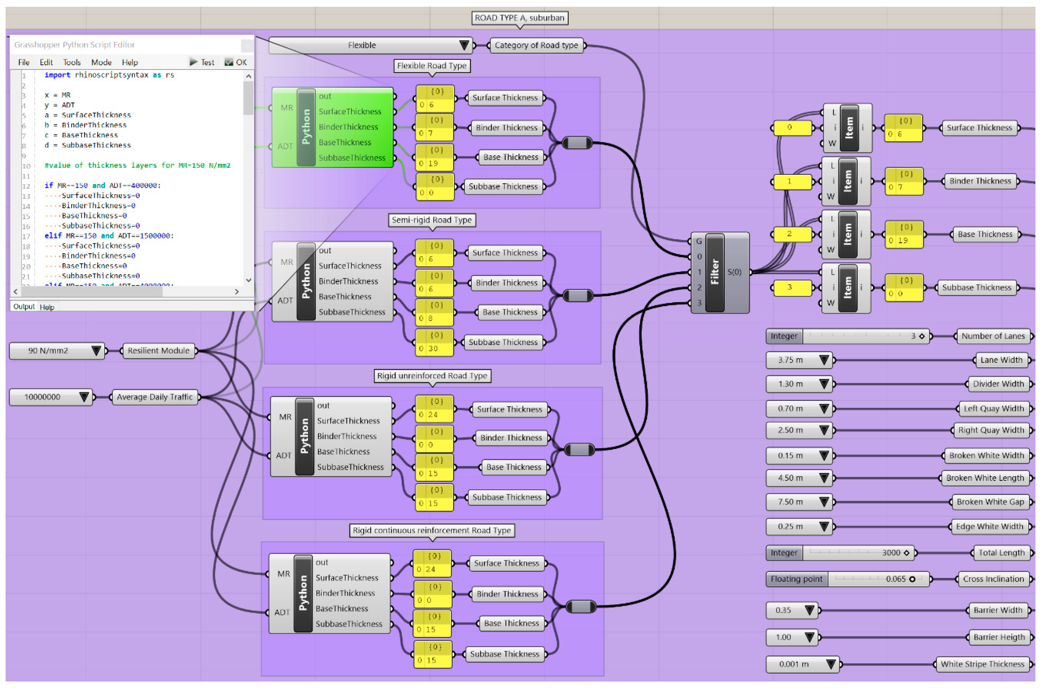
First of all, the input parameters for the modeling of the road infrastructure are defined, according to the mentioned regulations, and through Grasshopper’s different components it is possible to choose the appropriate numerical values, according to the type of parameter used, namely:
- GHPython Script, to weave the values provided in the road pavement catalogue model through a series of statements written in the Python programming language. Indeed, the thickness of each layer of road pavement, namely Surface, Binder, Base and Subbase Thickness, is identified. Firstly, the category of the road structure is chosen, that can be flexible, semi-rigid, rigid unreinforced or rigid with continuous reinforcement. Secondly the Resilient Module and the Average Daily Traffic expected in the infrastructure are selected.
- Number Slider, in the form of Integer or Floating point for Number of Lanes, Total Length and Cross Inclination;
- Value List, which provides a list of individual values to choose from, adopted for the inputs of Lane Width, Divider Width, Left Quay Width, Right Quay Width, Broken White Width, Broken White Length, Broken White Gap, Edge White Width, Barrier Width, Barrier Height and White Stripe Thickness.
The data is graphically inserted in different groups according to the type of road to be designed, in such a way that the numerical values of the data change together with the road type, as indicated in the regulations.
Figure 4 shows the Group related to the Road Type A, suburban.
The same procedure has been realized for all the other road typologies according to Italian Design Standards (A, B, C1, C2, D, E, F1, F2 and F) to allow the designer to choose through Stream Filter component directly the typology of interest and visualize the desired structure. The full computer code is available as Supplementary Materials.
Indeed, the Filter processes a list of values, which are organized in the next step through a List Item component, which allows to extract the information contained in the Filter in an ordered way.
Every layer that makes up the road pavement has been constructed point by point by inserting the x and z coordinates that essentially define a rectangular shape. Then the Group “x coordinates of each layer” is constituted to define four points through Format components that have Divider Width and Pavement Width as input.
The Group “z coordinates of each layer” consists of four subgroups, one for each layer of the road pavement: Surface, Binder, Base and Subbase layer. In a subgroup as many Format components as necessary can be found, for the definition of the coordinates of the points that make up the layer. Input Data are Surface Thickness, Binder Thickness, Base Thickness, Subbase Thickness and PavementWidth*Tangens (CrossInclination). In particular, the last one can vary the inclination of the road pavement simply by changing the value of Cross Inclination in the input.
Once the points have been defined, the boundary edge curves of each layer of road pavement can be created thanks to the PolyLine component, which creates a closed polyline used as input for the Boundary Surface component that allows visualizing the planar surface in Rhinoceros. It is necessary to take into account the presence of the divider and the barrier for some road typologies.
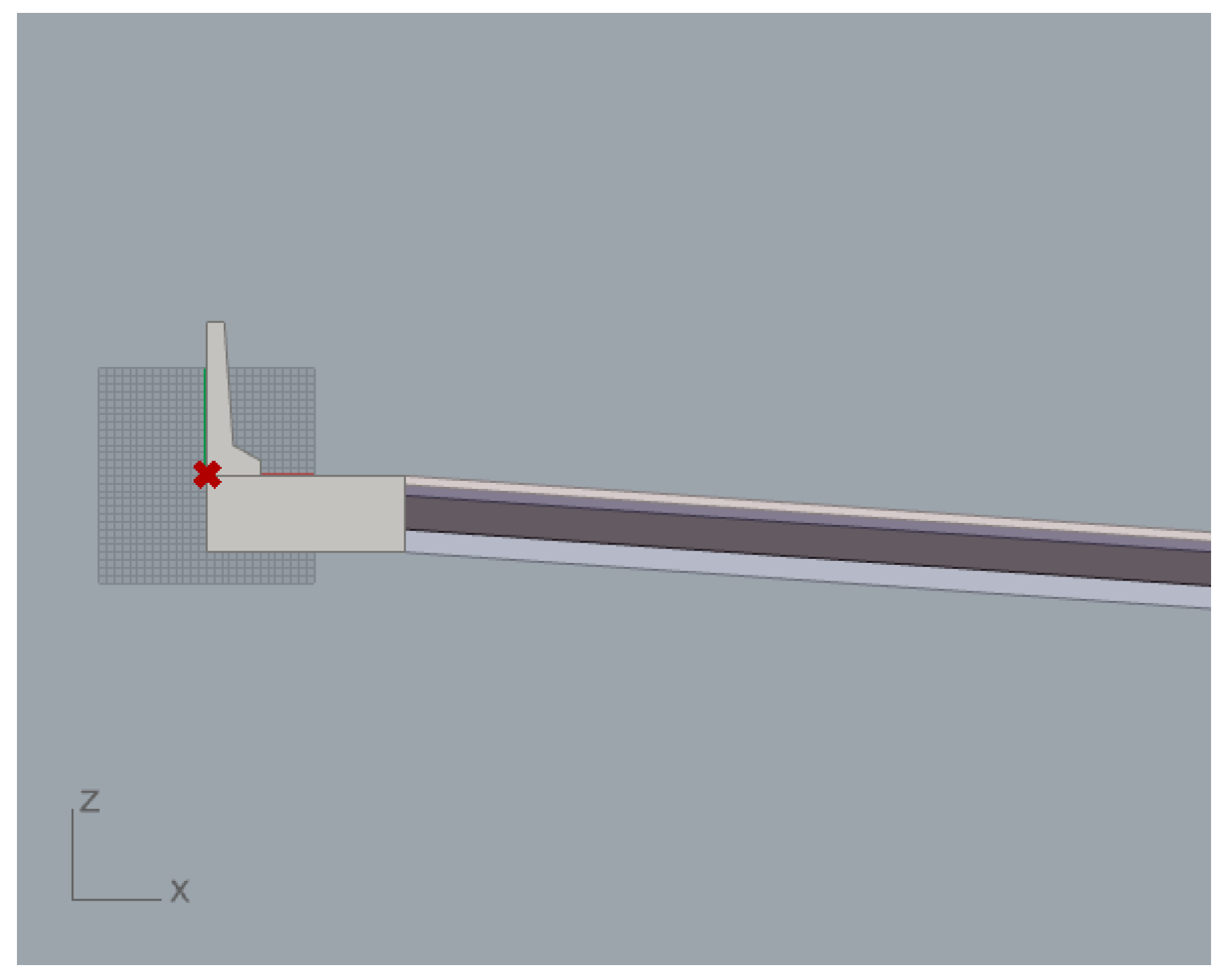
The construction of the Divider Foundation was done using a Rectangle component that consists of a Divider Width input function for the width and thickness of the Surface, Binder, Base and Subbase layers for the height. Finally, it is associated with the Boundary Surface component to create the planar surface.
The safety barrier is set up above the divider and a New Jersey-type barrier is chosen. As done for the road layers, the construction of the geometry of this object starts from the definition of the coordinates of the x and z points through various Formats that will have as input Barrier Width and Barrier Height. Then, through Construct Point, PolyLine and Boundary Surface components, the planar surface is constructed.
The divider foundation and barrier on the left side are shown in Figure 5.
All planar surfaces created with Boundary Surfaces must be extruded along the y-axis for a length equal to the Total Length input in order to view the 3D model. This is done for Surface, Binder, Base, Subbase layers, Left Barrier and Left Divider Foundation.
In addition, to complete the 3D model, the divider must also be on the right side of the road infrastructure, so the Move component is used, which has as input a vector that provides the distances of which the object must be moved.
The barrier must also be moved to the right, but in this case, it was preferred to adopt a different component, Mirror, which allows the figure to be mirrored with respect to a point on the yz plane; the midpoint long x with respect to the width of the pavement was chosen. Therefore, the Right Barrier was modelled.
These elements characterize the carriageway on the right.
The stripe of the outer edge of the road, Right Edge White, is built and positioned. First of all, the object is constructed as a rectangle whose sides are defined according to the Edge White Width and Total Length inputs. The obtained geometry is given a planar surface and via Move, the edge white stripe is placed in the outer edge of the road, on the right.
As for the construction and positioning of the Left Edge White (the inner edge stripe), two cases must be distinguished; the one in the presence of the safety barrier and the one in the absence of a safety barrier. The geometry used is always a Rectangle component, but the inputs and formulas vary due to the road type.
To decide which of the two solutions to adopt for Left Edge White, a GHPython Script was created to carry out an “if” and “other” statement.
Both Right Edge White stripe and Left Edge White stripe were extruded in the z direction to provide thickness and slope (rotation) of the road.
To construct and distribute the longitudinal discontinuous stripes, called Broken White, different algebraic components such as Addition, Integer Division and Modulus components are used to provide the length of the element to be repeated and to consider if there is a piece of stripe remaining and how long it is in relation to the total length of the road.
The construction of the rectangle that forms the single Broken White is implemented through the three Series components; the first two define the width and length of the stripe, the third defines how many times the element must be repeated in relation to the length of the road.
The constructed rectangle is then positioned through the Move component and assigned a planar surface through Boundary Surface component.
Length of the last stripe stretch may not fit entirely and may therefore be cut depending on the Total Length chosen. To calculate the stripe cut the components Equals, Filter, Modulus and Boolean are used.
If present, the last piece of the stripe is constructed as a rectangle and positioned using Move. Its shape is defined with Boundary Surface and finally extruded in the z direction to provide thickness.
The approach is useful to build and distribute a single longitudinal discontinuous stripe, which must be suitably positioned if the road type is two-lane or three-lane. This is the reason why the geometry of the Broken White stripe is analyzed by the Filter component to determine the presence or absence of the stripes as a function of Lane Width and Number of Lanes for the road type.
The obtained geometry is then correctly positioned along the x axis using Move and rotated using Rotate according to the Cross Inclination.
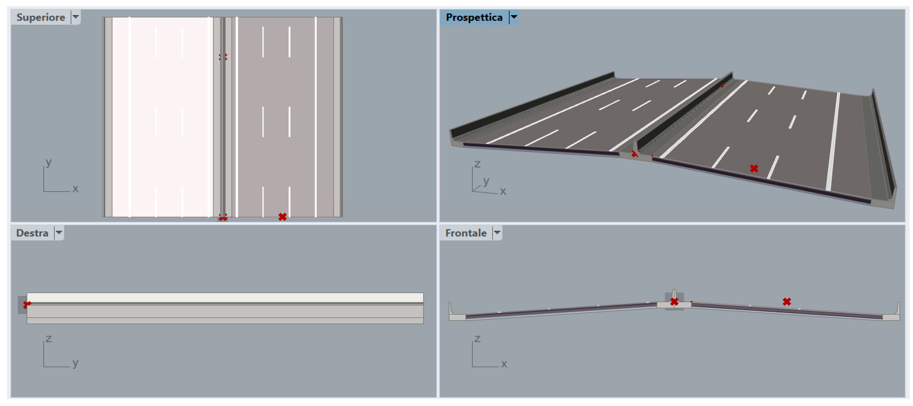
The built geometries are mirrored with a Mirror around the yz plane to obtain the lane on the left. This is implemented with Surface, Binder, Base, Subbase, Left and Right Barrier, Left and Right Divider, Left and Right Edge White stripes and Broken White stripes. The complete road infrastructure model implemented in Rhinoceros is shown in Figure 6.
Hence, the developed model can reproduce any road typology present in the Italian scenario and can support the design of new ones due to the possible parameterization of its elements.
Precisely for this reason, it would also be enough to replace the set of input parameters to the model with alternative parameter sets provided by any other road design regulations in order to quickly obtain a 3D model that meets the new requirements.
3. Results
To make the Grasshopper-based geometry model editable in Rhino, the Geometry component is necessary to “bake” all the latest obtained geometries. The baking action generates new geometry into the Rhino document based on the current state of the Grasshopper graph.
The downside of the bake rendering is the difficulty of performing any new changes on all the different parameters; still, the designer can proceed manipulating all infrastructure objects within Rhinoceros software.
VisualARQ is a plugin for Rhinoceros that implements an IFC import and export for exchange of the IFC 2×3 files between Rhinoceros and other AEC software packages.
The VisualARQ’s IFC label functionality allows assignment of IFC properties to objects before they are exported in the IFC format. These properties include an IFC type, a name, a description and a label.
For example, element IfcSlab is assigned to the divider, surface, binder, base and subbase layers; IfcWall is assigned to barrier, and finally, IfcDiscreteAccessory is assigned to edge and discontinuous stripes.
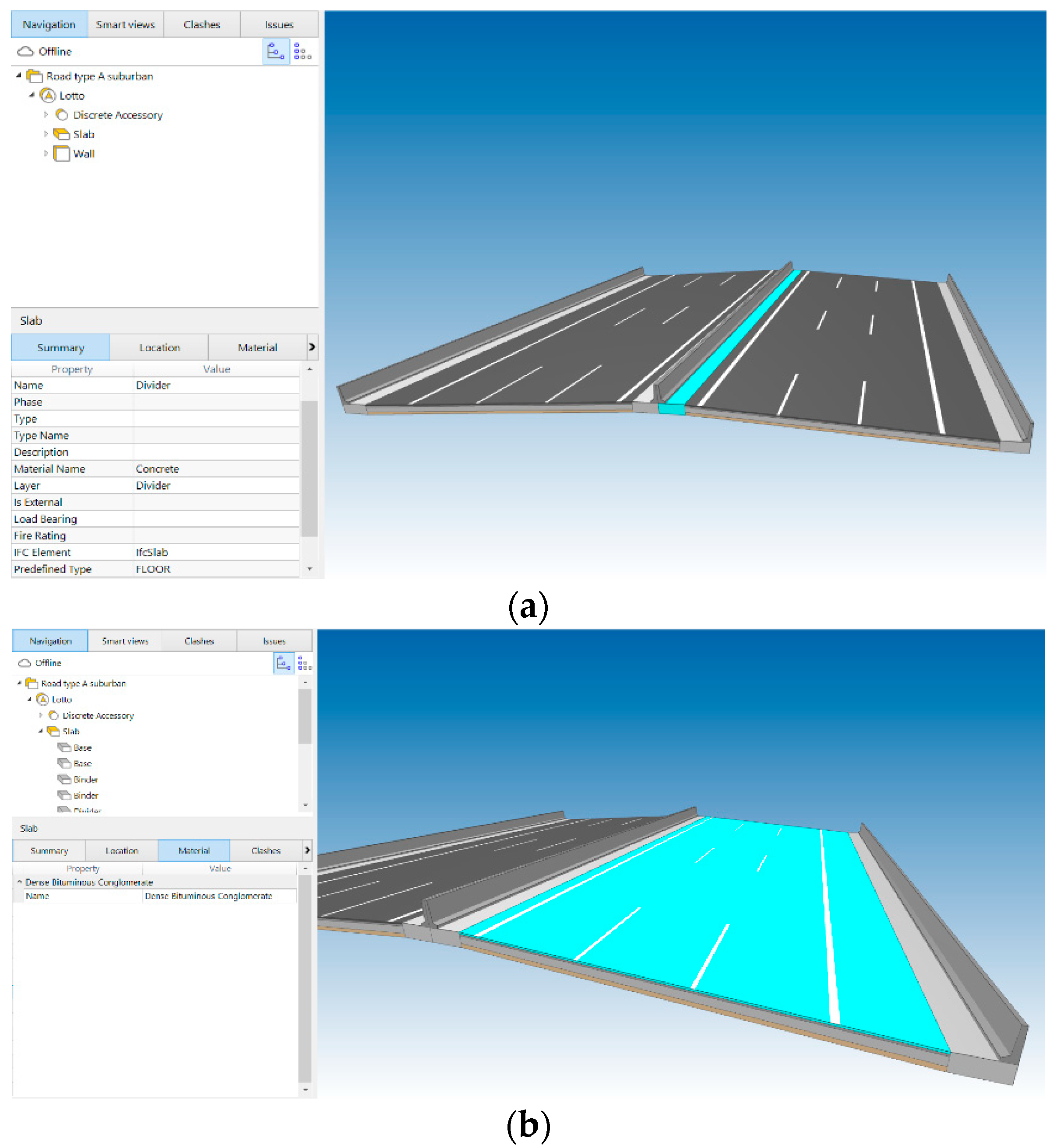
The last step in the creation of the road infrastructure is the verification of the IFC model using an IFC model viewer, in this case BIMcollab ZOOM, which is also a BIM validation tool fully integrated in issue management workflows.
Figure 7 shows the visualization of the IFC model, its structure and corresponding information related to the model, name, material name, layer and IFC element.
The parametric modeling of the road section developed through the combined use of Grasshopper, Rhinoceros, VisualARQ and BIMcollab ZOOM software, is examined and compared to the model developed with Civil 3D and Dynamo.
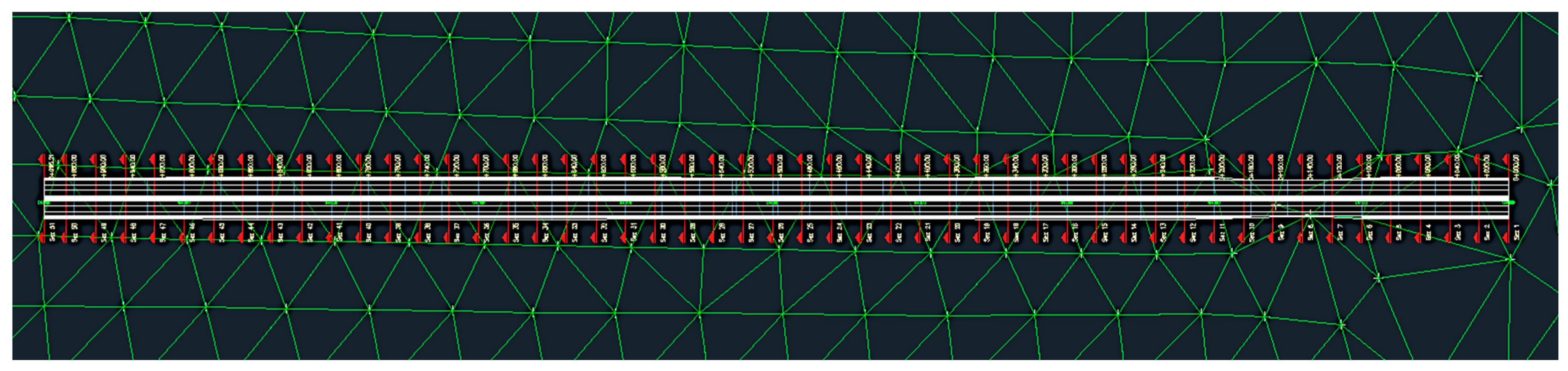
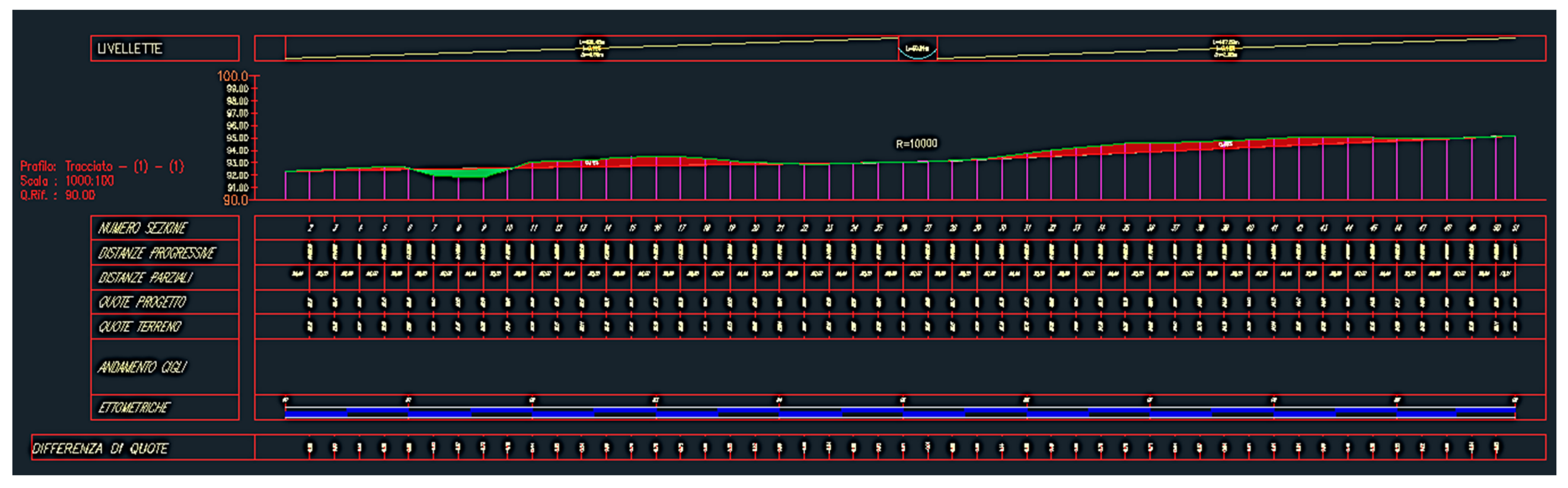
Civil 3D starts with the creation of the Digital Terrain Model (DTM) using triangulated irregular network (TIN) method, and then with the road alignment design (Figure 8).Then, the road vertical profile with the indication of the relative elevations and the corresponding slopes is carried out as shown in Figure 9. In addition, it is also possible to draw the diagram of the admissible speeds for the chosen road type, providing additional information about road regulations.
Moreover, based on the above road layout and the vertical profile, Civil 3D makes it possible to extract the sections of the road, detailing the trenches and embankments. As outputs, the quantities of excavation and fill and the volumes expected for each course of the road pavement and safety barriers are obtained. The quantification of the road earthworks provides useful information for construction works.
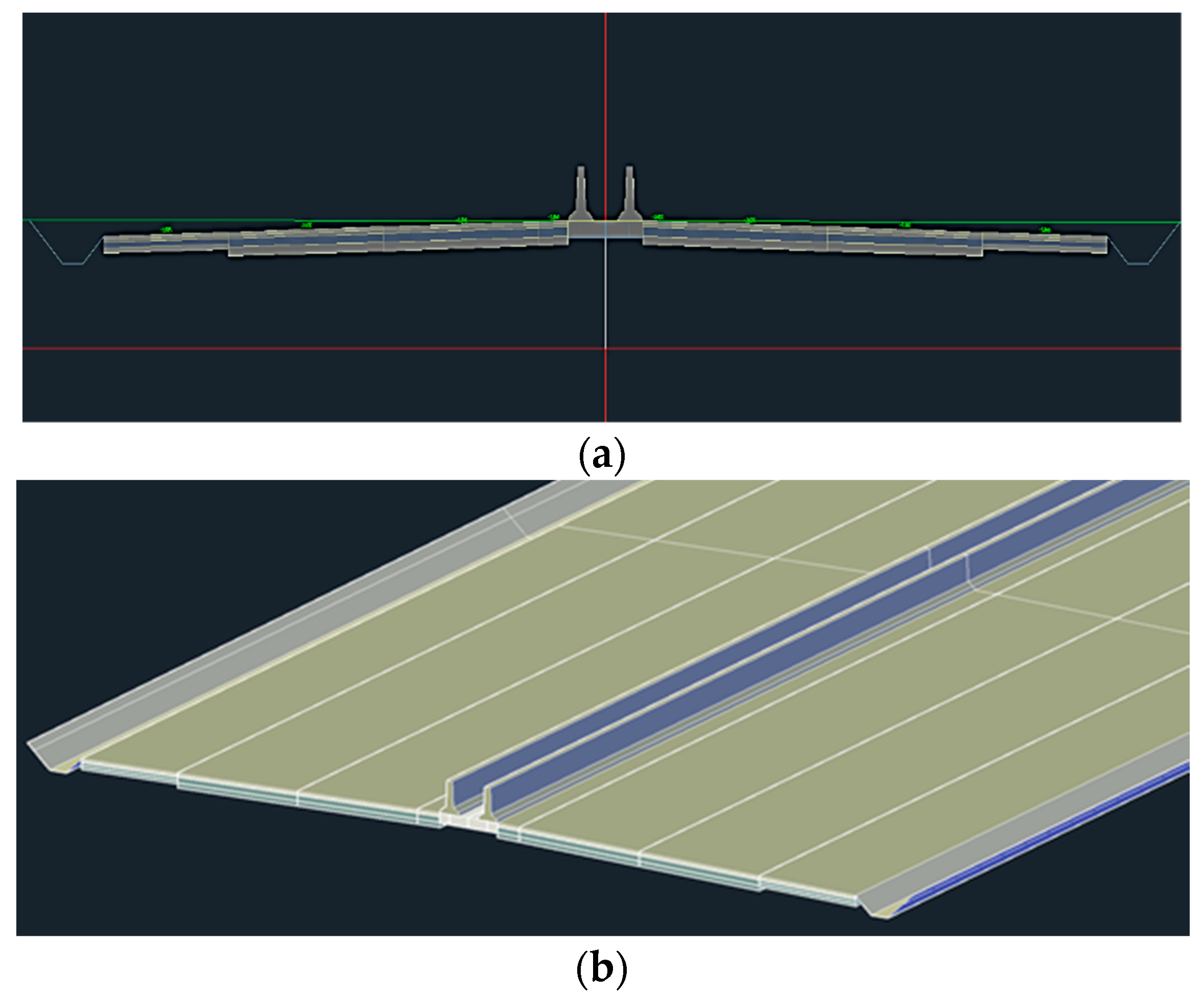
Figure 10 presents the designed road, type A, according to the Italian standards.
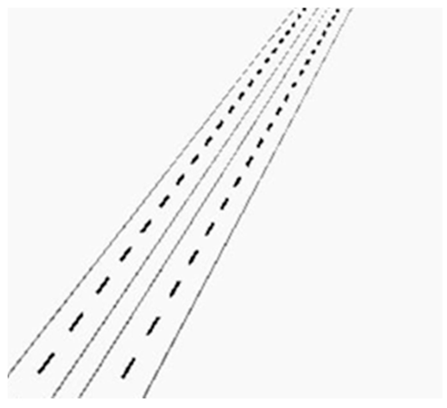
Once the characteristic geometrical elements are defined the “archi-node”, a flow diagram in Dynamo is used for the design of the horizontal markings (Figure 11) and the guardrail.
4. Discussion
The paper presents a new procedural model for the design of a road infrastructure, based on the implementation of visual programming languages with which the road geometry can be designed accordingly by adjusting the values of the input parameters and through the use of programming codes.
The three use cases of the conceptually similar procedure were presented. First, the OpenSCAD approach provides only geometric information but does not enable further semantic enrichment of the geometrical objects. Therefore, this software does not go beyond the creation of a 3D model and does not allow the creation of a BIM model. Therefore, in the next use case, road design is further investigated through the combined use of Rhinoceros and Grasshopper, which are combined with the Python code. With Python, it was possible to add more information about the dimensioning of the road in a more flexible way than in the OpenSCAD.
With Rhinoceros andGrasshopper a 3D model complete with semantic information has been developed. The VisualARQ plug-in enabled the assignment of the IFC properties to each element of the 3D model of the road infrastructure.
The current IFC scheme still does not contain specific entities for the adequate representation of roads. Each element of the infrastructure has been assigned to the most appropriate available IFC entity that best corresponds to its structural and functional characteristics.
Secondly, it should be noted that although several BIM software tools support the IFC 4×1 standard, Rhinoceros with the VisualARQ plugin supports only the use of the IFC 2×3 exchange format. Rhinoceros assigns each geometric element to a layer, and allows for the specification of material information, however, this information is lost at the time of conversion to the IFC file format. To surpass this problem, information about the infrastructure materials was manually inserted in the IFC file.
This procedure allows the required information to enrich the file and confirm the correct connection between element and material.
In contrast, for the model obtained with the Civil 3Droad design software, a more accurate comparison can be made with the Rhinoceros model.
Civil 3D features functionality for implementation of the reference standard through the Country Kit. In addition, Civil 3D automatically prepares the drainage system of the road pavement as provided for in the standard, while in Rhinoceros, this requires implementation by the user.
Both Civil 3D and Rhinoceros can export the model in IFC format, but they need additional software (Revit and VisualARQ, respectively) to complete the exported IFC model.
Civil 3D and Dynamo are presented as consolidated road design tools, having all the tools and elements to elaborate a complete road infrastructure; also providing summary tables of the volumes of excavation, landfill and of the pavement layers. This is not implemented automatically in Rhinoceros and Grasshopper, but it can be achieved because the software combination has the advantage of being very flexible by exploiting the different programming languages it supports.
Moreover, the model realized through Grasshopper can be promptly visualized and can reproduce a section of any road typology present in the Italian scenario. With the modification of the set parameter, any other road design regulations can be implemented.
Although Rhinoceros and Grasshopper are primarily not road design software, they support features that make them promising for future applications in the field of infrastructure BIM.
5. Conclusions
This study highlighted the integration of software in a BIM workflow using procedural modeling as the main approach for the design of road infrastructures. The approach gives designers parametric control requiring knowledge of scripting (OpenScad) and programming languages (i.e., Rhino–Grasshoper, Python) necessary to achieve a result in line with current infrastructure design regulations.
Currently, it is up to the designers to deal with the effective tool for their own purposes, based on the local legislation and personal knowledge which must be multidisciplinary and open to different programming code languages.
Supplementary Materials
The following are available online at http://0-doi-org.brum.beds.ac.uk/10.5281/zenodo.3757120, OpensSCAD and Python in Grasshopper full computer code.
Author Contributions
Conceptualization, A.T. and S.A.B.; data curation, A.C. and. S.G.d.O., methodology, A.T., A.C. and S.A.B.; visualization, A.C.; supervision, A.T. and S.A.B.; original draft preparation, A.C.; writing—review and editing, S.A.B., A.T. and S.G.d.O. All authors have read and agreed to the published version of the manuscript.
Funding
This work was supported by Federico II University of Naples as part of the Agreement of Cooperation with STAR Lab, University of Washington, Seattle, WA, USA.
Acknowledgments
The Authors would like to thank the University of Maribor and Federico II University of Naples for providing the BIM-tools licenses investigated in this study.
Conflicts of Interest
The authors declare no conflict of interest.
References
- Ng, S.T.; Xu, F.J.; Yang, Y.; Lu, M. A master data management solution to unlock the value of big infrastructure data for smart, sustainable and resilient city planning. Procedia Eng. 2017, 196, 939–947. [Google Scholar] [CrossRef]
- Mgbere, C.; Knyshenko, V.A.; Bakirova, A.B. Building information modeling. A management tool for Smart City. In Proceedings of the 2018 IEEE 13th International Scientific and Technical Conference on Computer Sciences and Information Technologies (CSIT), Lviv, Ukraine, 11–14 September 2018; Article number 8526634. pp. 177–182. [Google Scholar]
- Kupriyanovsky, V.; Alenkov, V.; Sokolov, I.; Zazhigalkin, A.; Klimov, A.; Stepanenko, A.; Sinyagov, S.; Namiot, D. Smart infrastructure, physical and information assets, Smart Cities, BIM, GIS, and IoT. Int. J. Open Inf. Technol. 2017, 5, 55–86. [Google Scholar]
- Geospatial World. Available online: https://www.geospatialworld.net/blogs/bim-smart-cities/ (accessed on 4 March 2020).
- Hassnain, R.; Waqas, T.; Seungsoo, L.; Jongwon, S. Flexible Earthwork BIM Module Framework for Road Project. In Proceedings of the 34th International Symposium on Automation and Robotics in Construction (ISARC 2017), Taipei, Taiwan, 28 June–1 July 2017; pp. 410–451. [Google Scholar]
- Bradley, A.; Li, H.; Lark, R.; Dunn, S. BIM for infrastructure: An overall review and constructor perspective. Automat. Constr. 2016, 71, 139–152. [Google Scholar] [CrossRef]
- Pasetto, M.; Giordano, A.; Borin, P.; Giacomello, G. Integrated railway design using Infrastructure-Building Information Modeling. The case study of the port of Venice. Transp. Res. Procedia 2020, 45, 850–857. [Google Scholar] [CrossRef]
- Singer, D.; Borrmann, A. A Novel Knowledge-Based Engineering Approach for Infrastructure Design. In Proceedings of the Fourth International Conference on Soft Computing Technology in Civil, Structural and Environmental Engineering, Prague, Czech Republic, 1–4 September 2015. [Google Scholar]
- Chong, H.Y.; Lopez, R.; Wang, J.; Wang, X.; Zhao, Z. Comparative Analysis on the Adoption and Use of BIM in Road Infrastructure Projects. J. Manag. Eng. 2016, 32, 05016021. [Google Scholar] [CrossRef]
- Dell’Acqua, G.; Guerra De Olivera, S.; Biancardo, S.A. Railway-BIM: Analytical review, data standard and overall perspective. Ingegneria Ferroviaria 2018, 11, 901–923. [Google Scholar]
- Abbondati, F.; Biancardo, S.A.; Palazzo, S.; Capaldo, F.S.; Viscione, N. I-BIM for Airport Infrastructures. Transp. Res. Proc. 2019, 45, 596–603. [Google Scholar] [CrossRef]
- AEC Excellence Awards 2017. Foster + Partners and FR-EE Take off with BIM AEC. Available online: https://www.autodesk.com/solutions/bim/hub/aec-excellence-2017/infrastructure/first-place (accessed on 31 March 2020).
- AEC Excellence Awards 2018. Improving Design & Approvals for a Monorail. Available online: https://www.autodesk.com/solutions/bim/hub/aec-excellence-2018/infrastructure/finalists/taejongdae-monorail (accessed on 31 March 2020).
- Recognizing AEC Brilliance. Available online: https://excellenceawards.autodesk.com/ (accessed on 31 March 2020).
- Tschuchnigg, F.; Lederhilger, C. BIM in Geotechnics—Application to Road and Railway Construction. In Proceedings of the International Conference on Information technology in Geo-Engineering, Guimarães, Portugal, 29 September–2 October 2019; pp. 471–482. [Google Scholar]
- Khan, N.; Ali, A.K.; Skibniewski, M.J.; Lee, D.J.; Park, C. Excavation Safety Modeling Approach Using BIM and VPL. Adv. Civ. Eng. 2019, 2019, 1515808. [Google Scholar] [CrossRef] [Green Version]
- Shaaban, K.; Nadeem, A. Professionals’ perception towards using building information modelling (BIM) in the highway and infrastructure projects. Int. J. Eng. Manag. Econ. 2015, 5, 273. [Google Scholar] [CrossRef]
- Georgoula, V. Development of an Autodesk Revit Add- in for the Parametric Modeling of Bridge Abutments for BIM in Infrastructure. Master’s Thesis, Technical University of Munich, Munich, Germany, 2019. Available online: https://publications.cms.bgu.tum.de/theses/2019_Georgoula_Vilgertshofer.pdf (accessed on 31 March 2020).
- Slobodchikov, R.; Bakke, K.L.; Svennevig, P.R.; O’Born, R. Implementing climate impacts in road infrastructure in the design phase by combining BIM with LCA. In Proceedings of the IOP Conference Series: Earth and Environmental Science, Graz, Austria, 11–14 September 2019; Volume 323. [Google Scholar]
- Tang, F.; Ma, T.; Zhang, J.; Guan, Y.; Chen, L. Integrating three-dimensional road design and pavement structure analysis based on BIM. Autom. Constr. 2020, 113, 103152. [Google Scholar] [CrossRef]
- Amer, A.H.; Hasan, O. Level of detail (LOD) specifications, standards and file-format challenges in infrastructure projects for BIM level three. WIT Trans. Built Environ. 2017, 169, 143–154. [Google Scholar]
- Liu, B.; Cai, T.; Xiao, S.; Fu, H.; Chu, W. Research on application of BIM technology in municipal road construction. In Proceedings of the IOP Conference Series: Earth and Environmental Science, Graz, Austria, 11–14 September 2019; Volume 330. [Google Scholar]
- Chen, L.; Shi, P.; Tang, Q.; Liu, W.; Wu, Q. Development and application of a specification-compliant highway tunnel facility management system based on BIM. Tunn. Undergr. Space Technol. 2020, 97, 103262. [Google Scholar] [CrossRef]
- Costin, A.; Adibfar, A.; Hu, H.; Chen, S.S. Building Information Modeling (BIM) for transportation infrastructure—Literature review, applications, challenges, and recommendations. Automat. Constr. 2018, 94, 257–281. [Google Scholar] [CrossRef]
- Floros, G.S.; Boyes, G.; Owens, D.; Ellul, C. Developing IFC for infrastructure: A case study of three highway entities. In Proceedings of the ISPRS Annals of the Photogrammetry, Remote Sensing and Spatial Information Sciences, Singapore, 24–27 September 2019. [Google Scholar]
- Ozturk, G.B. Interoperability in building information modeling for AECO/FM industry. Automat. Constr. 2020, 113, 103122. [Google Scholar] [CrossRef]
- Al Sayed, K.; Bew, M.; Penn, A.; Palmer, D.; Broyd, T. Modelling dependency networks to inform data structures in BIM and smart cities. In Proceedings of the 10th International Space Syntax Symposium, London, UK, 13–17 July 2015. [Google Scholar]
- Vilgertshofer, S.; Borrmann, A. Using graph rewriting methods for the semi-automatic generation of parametric infrastructure models. Adv. Eng. Inf. 2017, 33, 502–515. [Google Scholar] [CrossRef]
- Ministero delle Infrastrutture e dei Trasporti. Decreto Ministeriale 5 novembre 2001, n. 6792 (S.O. n.5 alla G.U. n.3. del 4.1.02). Norme Funzionali e Geometriche per la Costruzione delle Strade. Available online: http://www.mit.gov.it/mit/mop_all.php?p_id=1983 (accessed on 4 March 2020).
- Consiglio Nazionale delle Ricerche. Catalogo delle Pavimentazioni Stradali; Consiglio Nazionale delle Ricerche: Roma, Italy, 1995. [Google Scholar]
- Decreto del Presidente della Repubblica. Regolamento di Esecuzione e di Attuazione del Nuovo Codice della Strada, 16 Dicembre 1992, n. 495. Available online: https://www.gazzettaufficiale.it/eli/id/1992/12/28/092G0531/sg (accessed on 4 March 2020).
Figure 1.
Fragment of the script: Road length and road type.

Figure 2.
Road layers section with guardrail on the left roadside.

Figure 3.
Road Type: (a) Freeway: Type A; (b) Minor arterial: Type C.

Figure 4.
Algorithm overview for the construction of the road infrastructure.

Figure 5.
Road layers, divider and barrier planar surfaces.

Figure 6.
Road type freeway Type A as a result the procedural model.

Figure 7.
Visualization of the IFC Road model exported from Rhinoceros/VisualARQ in the BIMcollab ZOOM viewer. (a) Information about the road divider; (b) Material information for the road surface course.
Figure 7.
Visualization of the IFC Road model exported from Rhinoceros/VisualARQ in the BIMcollab ZOOM viewer. (a) Information about the road divider; (b) Material information for the road surface course.

Figure 8.
Top view of the road modelon the Digital Terrain ModelDTM.

Figure 9.
Terrain and road vertical profiles.

Figure 10.
Freeway Type A Section, (a) Cross sectional view of the road; (b) 3D view.

Figure 11.
Road markings as designed in Dynamo.

© 2020 by the authors. Licensee MDPI, Basel, Switzerland. This article is an open access article distributed under the terms and conditions of the Creative Commons Attribution (CC BY) license (http://creativecommons.org/licenses/by/4.0/).
Share and Cite
MDPI and ACS Style
Biancardo, S.A.; Capano, A.; de Oliveira, S.G.; Tibaut, A. Integration of BIM and Procedural Modeling Tools for Road Design. Infrastructures 2020, 5, 37. https://0-doi-org.brum.beds.ac.uk/10.3390/infrastructures5040037
AMA Style
Biancardo SA, Capano A, de Oliveira SG, Tibaut A. Integration of BIM and Procedural Modeling Tools for Road Design. Infrastructures. 2020; 5(4):37. https://0-doi-org.brum.beds.ac.uk/10.3390/infrastructures5040037
Chicago/Turabian StyleBiancardo, Salvatore Antonio, Alessandra Capano, Sara Guerra de Oliveira, and Andrej Tibaut. 2020. "Integration of BIM and Procedural Modeling Tools for Road Design" Infrastructures 5, no. 4: 37. https://0-doi-org.brum.beds.ac.uk/10.3390/infrastructures5040037