Article

Optimization of Reinforced Concrete Retaining Walls Designed According to European Provisions

by
Foteini Konstandakopoulou
1,
Maria Tsimirika
2,
Nikos Pnevmatikos
3 and
George D. Hatzigeorgiou
1,*
1
School of Science and Technology, Hellenic Open University, 26 335 Patras, Greece
2
Administrative Region of Eastern Macedonia and Thrace, 65110 Kavala, Greece
3
Department of Civil Engineering, School of Mechanics, University of West Attica, 122 41 Egaleo, Greece
*
Author to whom correspondence should be addressed.
Submission received: 6 April 2020 / Revised: 31 May 2020 / Accepted: 3 June 2020 / Published: 5 June 2020

Abstract

:
Reinforced concrete retaining walls are concrete structures that are built to retain natural soil or fill earth. This study examines the lower cost-optimized design of retaining walls. Recently, a large number of modern optimization techniques were published, but a small number of them were proposed for reinforced concrete retaining walls. The proposed method develops a heuristic optimization approach to achieve the optimal design of these structures. This method simultaneously satisfies all structural, geotechnical, and European Code design restraints while decreasing the total cost of these structures. In order to confirm the efficiency and accuracy of the proposed method, characteristic retaining wall examples are demonstrated. Furthermore, the parametric investigation is examined to study the result of pertinent parameters on the minimum-cost static and seismic design of retaining structures.

1. Introduction

Reinforced concrete retaining walls (RCRW) set up an essential part of infrastructures which are commonly erected for various applications, generally for road and transportation structures, bridge abutments, lifelines, etc. RCRW must safely and consistently support the backfill ground and have enough stability against sliding and overturning failures. Furthermore, crucial stresses in both the structure and the soil should be limited to avoid all failure modes, using appropriate values of safety factors, e.g., the foundation should have enough bearing capacity while tensile stresses are not allowed, since an ineffective area in the foundation–soil interface is developed. Moreover, various structural requirements for both foundation and wall should be fulfilled, e.g., these structural elements should have enough shear and moment capacity or the configuration of steel rebars should comply with structural code provisions.
Undeniably, the cost-effective objective is the leading apprehension of holders and engineers at the beginning of an engineering project. Nevertheless, it cannot state all the apprehensions for the entire estimated service period of an engineering project. With the intention of minimizing the total cost of RCRW while simultaneously satisfying design (geotechnical and structural) constraints, the engineer needs to examine a variety of dimensions and steel reinforcement, making the procedure of design quite tiresome and repetitive. Taking into account that it is particularly demanding to achieve a final design entirely sustaining the safety requirements, it is advantageous to set this procedure as an optimization problem. One can mention here the recent and pertinent works of Dembicki and Chi [1], Saribas and Erbatur [2], Rhomberg and Street [3], Sivakumar and Munwar [4], Yepes et al. [5], Kaveh and Behnam [6], Gandomi et al. [7], Moayyeri et al. [8], and Dagdeviren and Kaymak [9]. It should be mentioned that the reliable and minimum-cost design of a structure is one of the key objectives of engineering science. Minimization of cost in design in conjunction with the satisfaction of modern code provisions for structural safety can be reached using an optimization technique, which is a characteristic step of entirely engineering procedures. The objective of optimization can be achieved by means of heuristic or deterministic methods. The heuristic methods cannot at all times provide the finest overall results, but they are regularly found to attain a rather fast and almost global optimum result. On the other hand, a deterministic approach requires the objective function generally to be continuous, differentiable, and convex while a heuristic scheme is not constrained in the above-mentioned restrictions. Heuristic methods appear to have various procedures, for example, simulated annealing methods, genetic algorithm schemes, etc. These approaches are mostly beneficial for complicated optimization engineering problems where deterministic methods are frequently incapable of catching the optimal results within an affordable and rational time. Consequently, many research works were recently published to develop heuristic methods to elucidate difficult problems such as Lee et al. [10] for the optimization of trusses, Li et al. [11] to find optimal pin-jointed structures, Kaveh and Talatahari [12] for the optimum design of skeletal structures, and Minoglou et al. [13] where a heuristic algorithm was examined to find the optimum design of steel thin-wall tanks.
This study develops an optimization method for RCRW which is based on a heuristic algorithm. The optimization design constraints of the problem result from the provisions of European Codes and more specifically from Eurocode 2 [14] for the design of concrete sections (considering the bending moment–axial force–shear force triplet for all loading combinations), from Eurocode 7 [15] for the geotechnical design, and from Eurocode 8 [16] for the definition of earthquake loads. The proposed method is simple and effective, and the engineer can directly use the provided design charts and tables or the proposed empirical expression in order to (a) find the optimum dimensions of the retaining structure under his consideration taking into account both the regional seismic requirements and the local soil properties, and (b) compute the total cost of the retaining structure. Thus, in contrast to previous research studies, this work requires a small amount of time and effort to be applied, thereby avoiding difficult programming techniques. The paper is completed by presenting valuable conclusions about the effect of various parameters on the optimum design of RCRW.

2. Reinforced Concrete Retaining Walls

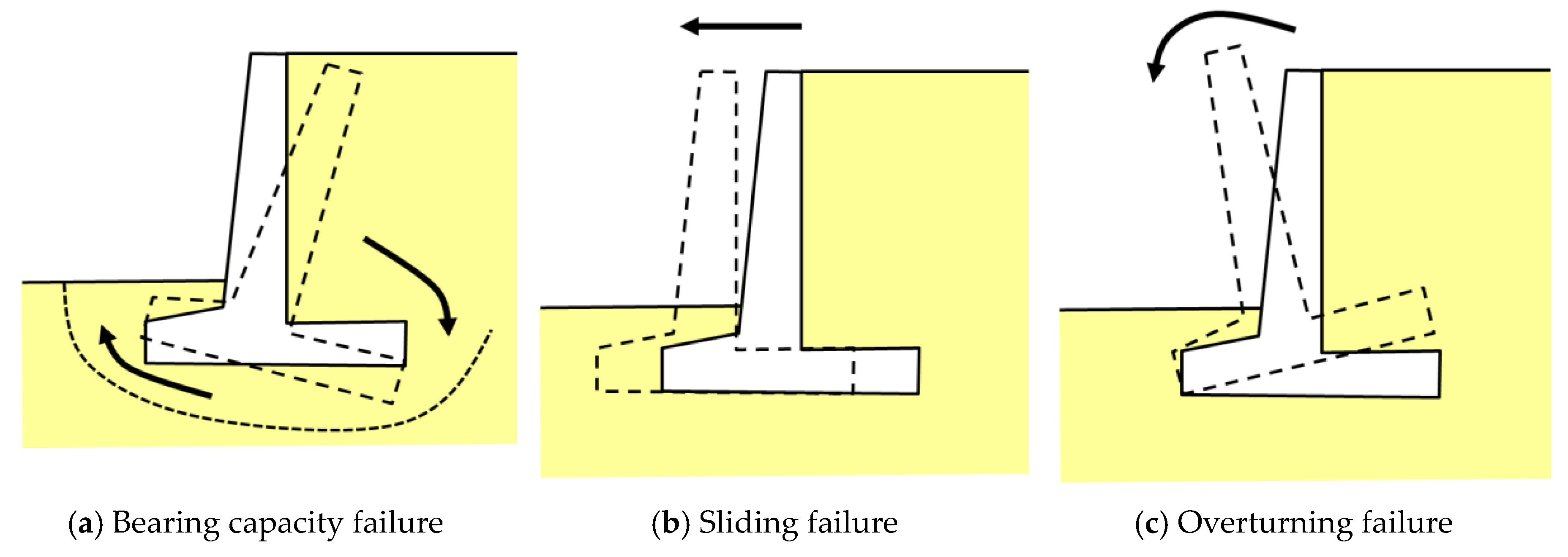
2.1. Design Procedures of Reinforced Concrete Retaining Walls

The design of reinforced concrete retaining walls involves two independent stages:
Stage 1. Stability checks (see Figure 1)
1a. Restraints related to bearing capacity
1b. Restraints related to sliding
1c. Restraints related to overturning
Stage 2. Section strength and steel reinforcement checks
RCRWs are constructed to resist horizontal soil pressures corresponding to both static and dynamic loads where their design takes into account the Eurocode 7 provisions for the calculation bearing resistance of shallow foundation with eccentric load, as well as Eurocode 8 provisions for bearing capacity in seismic condition [15,16]. The first scheme for computing the combined static and dynamic soil pressure on a RCRW was proposed by Okabe and Mononobe [17,18], which is also known as the Mononobe–Okabe technique. More specifically, this approach is based on the theory of plasticity and it appears to be an extension of the well-known theory of Coulomb [19], where the transient seismic loads are replaced by an appropriate static load. Consequently, the result of the seismic ground motion can be represented by equivalent inertial loads where they act at the gravity center of the soil–mass system [20]. The reader can also consult other improved pseudo-static or dynamic methods that extended or improved the Mononobe–Okabe method such as References [21,22,23].
The application of the Mononobe–Okabe approach for a typical RCRW is shown in Figure 2.
It should be mentioned that the Mononobe–Okabe method was initially developed for a dry cohesionless soil medium assuming that the soil and the wall behave as rigid bodies where the acceleration effectively becomes constant through the soil wedge mass. Furthermore, it is considered that the wall yields appropriately such that a triangular earth wedge behind the wall is formed at the point of initial failure with the maximum shear strength activated along the surface of sliding. According to the Mononobe–Okabe approach, the dynamic load, PAE, is given by
P A E = 1 2 γ H 2 ( 1 + K v ) cos 2 ( φ ο θ β ) cos θ cos 2 β cos ( δ + β + θ ) [ 1 + sin ( φ ο + δ ) sin ( φ ο θ i ) cos ( δ + β + θ ) cos ( i β ) ] 2 ,
where
θ = tan 1 ( K h 1 + K v ) .
In Equations (1) and (2), γ is the soil weight density, H is the height of the active pressure wedge, φο is the soil’s friction angle, i is the sloping of the ground surface, δ is the wall–soil friction angle, Kh and Kv are the design seismic factors in the horizontal and vertical direction, respectively, and θ is the seismic angle. It is worth noting that the abovementioned Mononobe–Okabe equations are valid for the case where i ≤ (φoθ), while, in the case where i > (φoθ), the sloping backfill behind the retaining wall will be unstable, especially if the soil medium has inadequate cohesive strength. Furthermore, there are more advanced approaches, such as the boundary element method [24], finite element method [25], and dynamic response analysis [26], which are more appropriate to simulate the dynamic behavior of the soil–wall system. However, these approaches are generally not used in everyday engineering routine for the analysis and design of RCRW under the action of seismic loads, while the Mononobe–Okabe approach seems to be simple, straightforward, and familiar in the engineering community. For this reason, the Mononobe–Okabe approach is examined here.

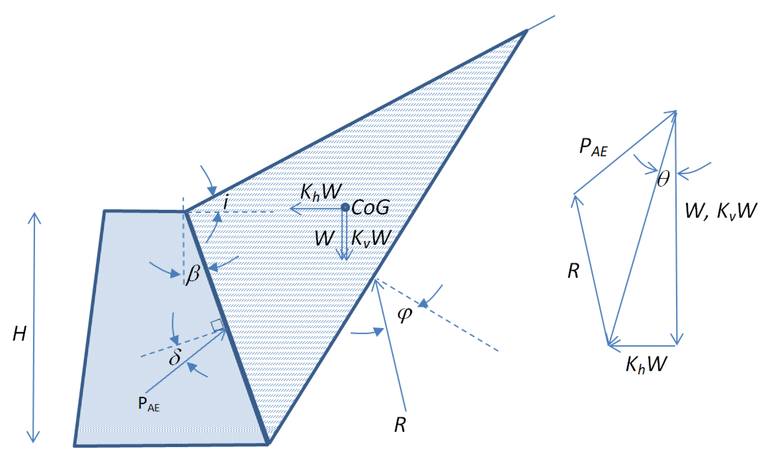
2.2. Design of Reinforced Concrete Retaining Walls According to European Codes

In this study, the analysis and design of reinforced concrete retaining walls are based on European Provisions, i.e., according to
  • Eurocode 2, for reinforced concrete structures [14],
  • Eurocode 7, for geotechnical design [15], and
  • Eurocode 8, for seismic design [16].
The aforementioned codes were implemented into BetonExpress software [27], a simple but effective analysis and design commercial program for reinforced concrete walls, as well as for simplified structures consisting of reinforced concrete.
Four basic typologies, named A1, A2, B1, and B2, of reinforced concrete retaining walls are examined here, as shown in Figure 3. It should be mentioned that the total height of soil on the left is equal to H, i.e., the height of the active pressure wedge (see also Figure 2).
It should be mentioned that the examined profiles of retaining walls are the most common ones applied in everyday engineering practice. Additionally, the symbol “1” is used to denote angle-shaped footing, while the symbol “2” corresponds to the constant section (or constant height) for the footing. Retaining walls type A have a relatively small back heel. In this case, the active earth pressure is computed using Coulomb’s theory [28] at the back face of the wall. On the other hand, retaining walls type B have an adequate back heel where the active earth pressure is computed using Rankine’s theory [28] at a vertical surface at the end of the heel. Thus, the appropriate adoption of different theories to quantify the active earth pressure has to do with the type and relative dimensions of the retaining wall under consideration, which was also noted by previous studies, e.g., Reference [29]. It is evident that the static earth pressure is evaluated using either Rankine’s or Coulomb’s approaches, but the Mononobe–Okabe solution is exclusively used for all types of retaining walls under seismic conditions. Indeed, seismic active earth pressures based on the Mononobe–Okabe solution or on the limit analysis theorems are in close agreement. This can be explained examining the log-spiral failure curves taken from limit analysis, which are practically planar [30]. Furthermore, planar failure surfaces were also found when executing dynamic model experimental tests using either centrifuge methods [31] or shaking tables [32].
It should be mentioned that angle-shaped footings are used to save material costs, but the labor and formwork costs are higher in comparison with constant-height footings. Furthermore, in order to develop a fairly broad databank for reinforced concrete retaining walls, the following cases are examined:
(1)
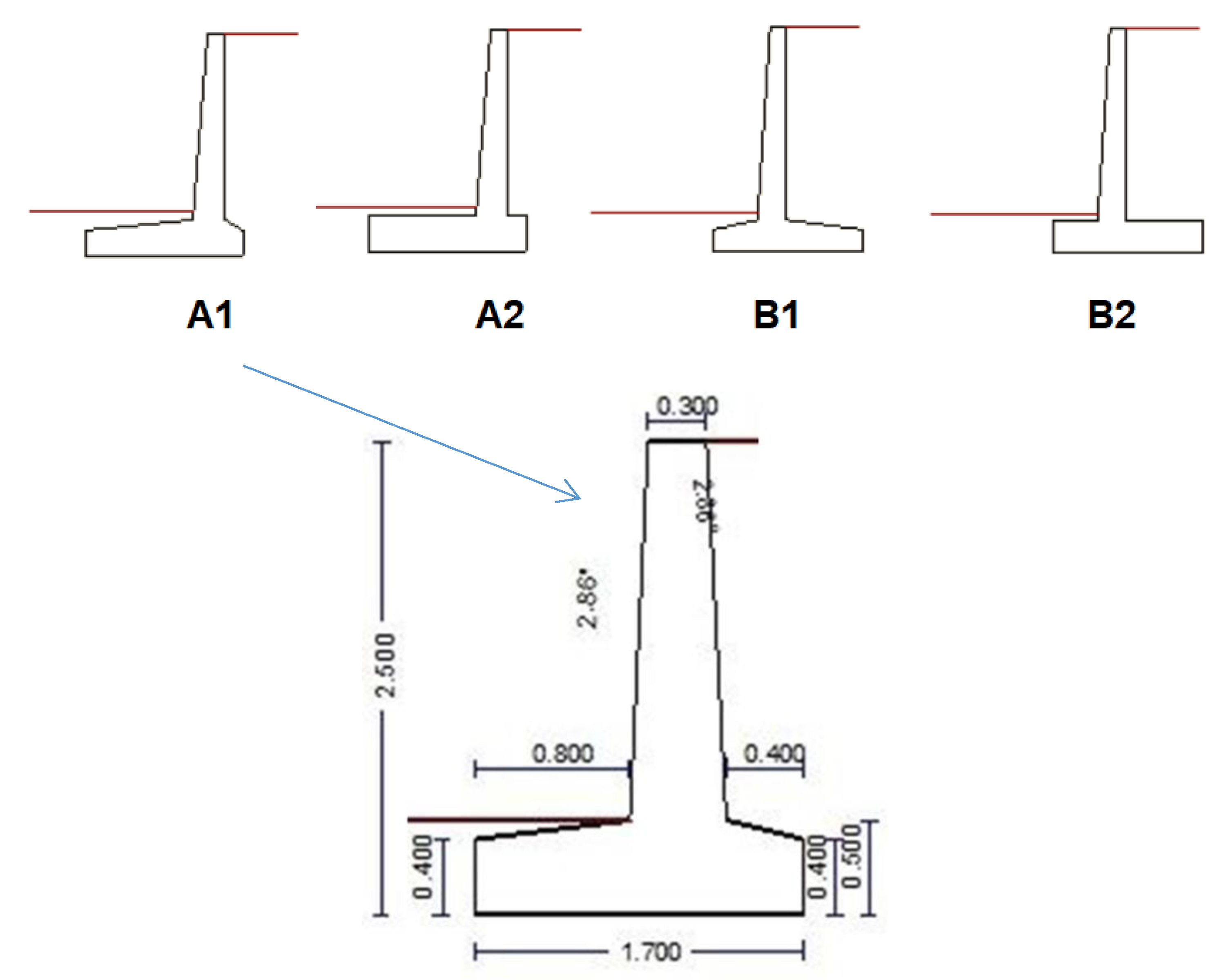
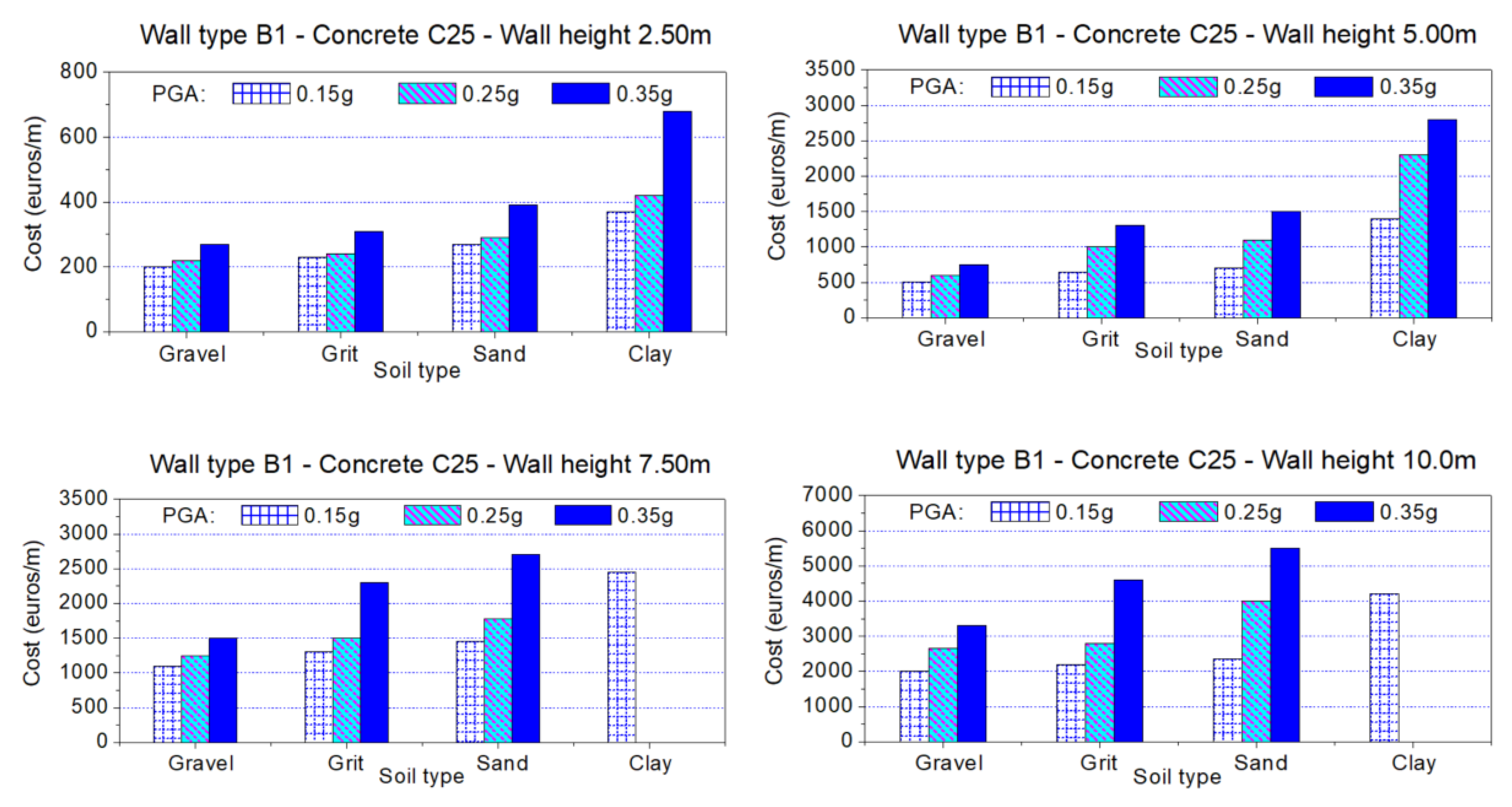
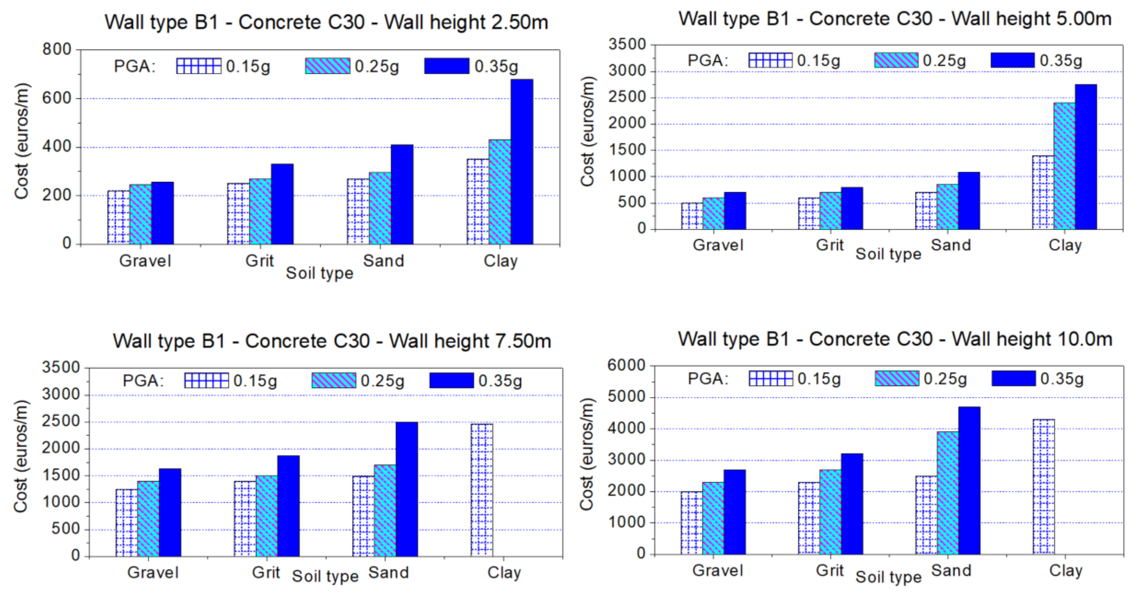
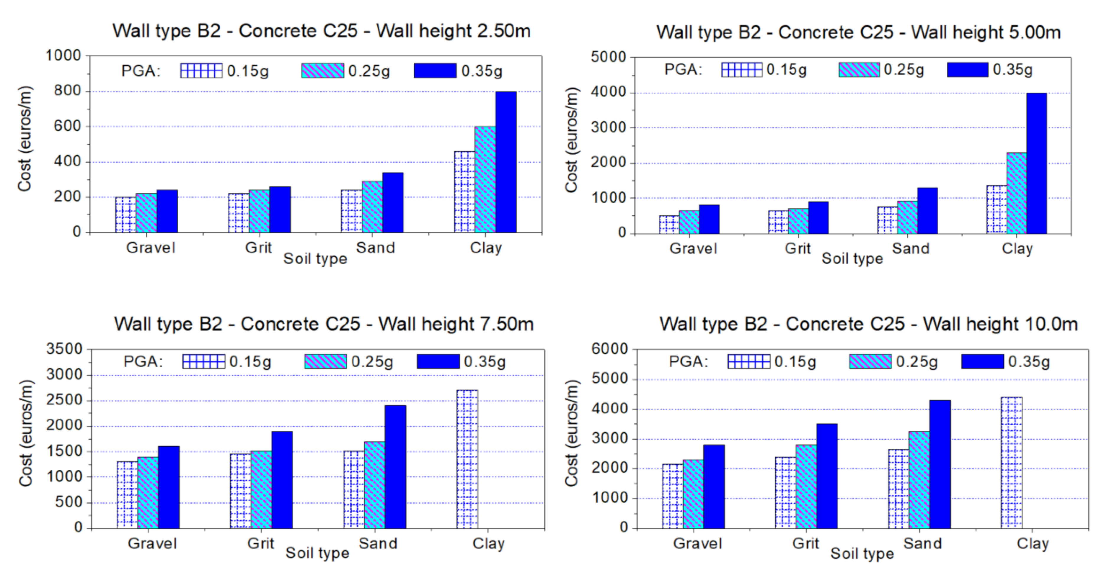
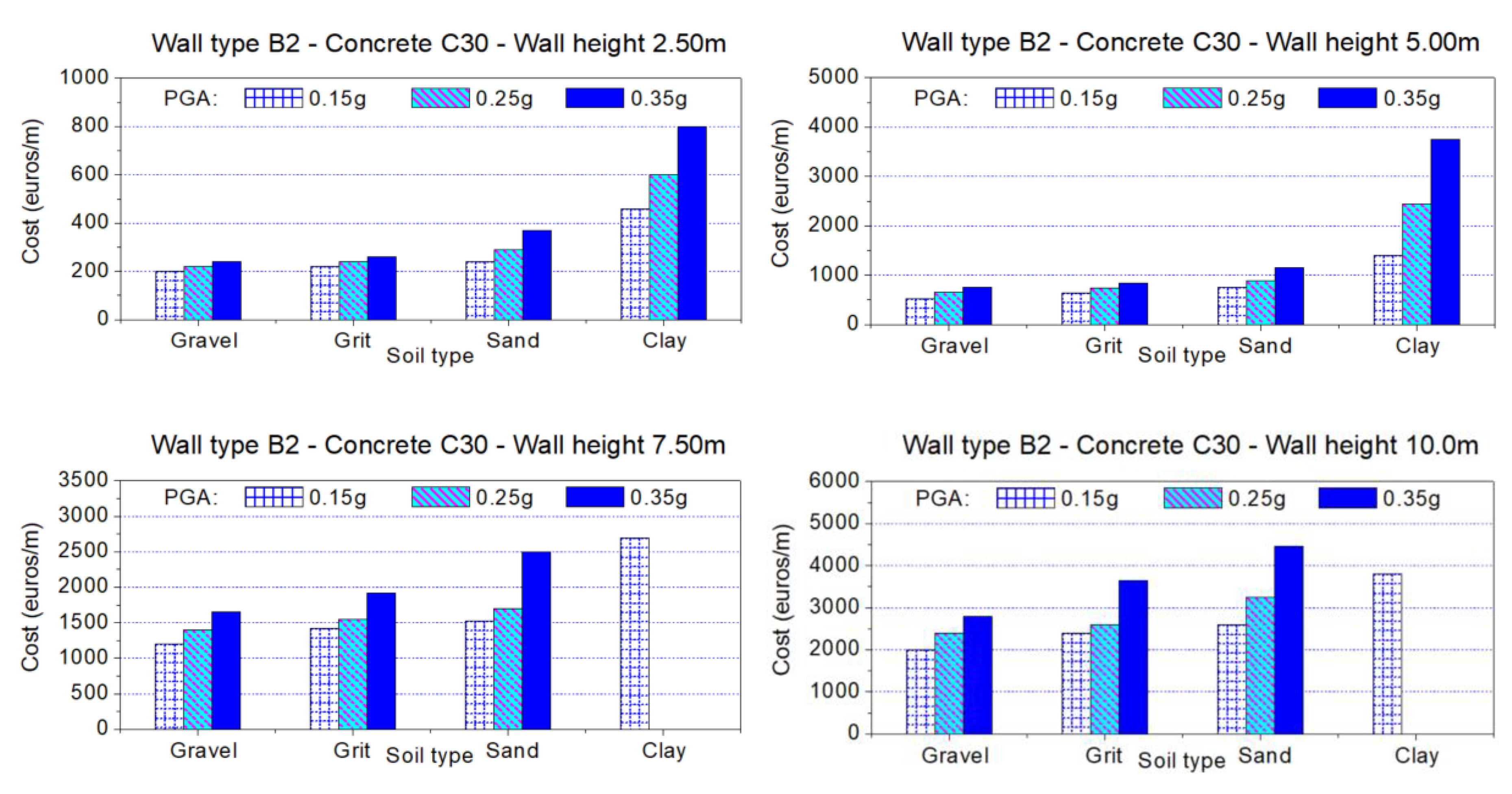
Four wall profiles: A1, A2, B1 and B2 (see Figure 3).
(2)
Two concrete grades C25 and C30, with compressive strength equal to 25 and 30 MPa, respectively.
(3)
Four different total heights: 2.5 m, 5.0 m, 7.5 m and 10.0 m.
(4)
Three values of peak ground acceleration, PGA, equal to 0.15 g, 0.25 g, and 0.35 g, which denote the seismic intensity.
(5)
Four different type of soil types, i.e., gravel, grit (sand–gravel), sand, and clay.
The steel rebars of reinforced concrete are not examined here as an additional parameter of the problem considering that, in southern Europe, steel rebars with yield stress 500 MPa (e.g., S500s, B500, etc.) are exclusively used today in everyday engineering practice.
The mechanical properties for the aforementioned soil types under consideration appear in Table 1.
Rankine’s theory assumes that the wall is frictionless (wall–soil friction angle, δ = 0) while, for Coulomb’s theory, it is assumed that δ = φo/2. Furthermore, BetonExpress software [27] requires the knowledge of compressive strength of soils, qu, under consideration, where this parameter is evaluated here using the American Society for Testing and Material (ASTM) standards for clay [33], for sand [34], and for grit and gravel soil types [35]. It should be mentioned that factorized geotechnical parameters in the Mononobe–Okabe formulation are used here in order to be compatible with European norms [16]. From the abovementioned five sets, all possible combinations are examined, i.e., 4 (wall profiles) × 2 (concrete grades) × 4 (wall heights) × 3 (PGAs) × 4 (soil types) = 4 × 2 × 4 × 3 × 4 = 384 different cases. All these design cases of retaining walls were designed using the force-based design approach of European provisions [16]. The basic objective of this study is to design all these (384) reinforced concrete retaining walls and, for any case with specific restraints, to determine the optimum dimensions for the parts of the structure, as well as the optimum reinforcement. The optimization has to do with the best possible way to provide the most economical solution, combined with the resistance of the wall against seismic loads. The results of this work could be an indicative guide for the designer to have a fairly realistic view of the optimal dimensions for the retaining wall and of the number of reinforcement bars, as well as a reliable evaluation for the cost of construction.
In order to achieve in any case the most economical solution, the material prices and labor cost (including taxes VAT) are taken into account according to current values of everyday engineering practice in Greece and other countries in southern Europe, such as Italy and Spain, where the engineering practice, the material and labor costs, and structural code provisions are common. The following costs are considered:
  • Excavation
  • Supply, transport on site, laying and compaction of concrete using a pump or tower crane
  • Supply, transport on site, setting of reinforced concrete bars
  • Molded wall formwork—placement and removal
  • Rebar spacers
  • Concrete maintenance
In order to quantify these, Table 2 depicts the analysis cost of the aforementioned works, which are applied in southern Europe (spring–summer 2020).

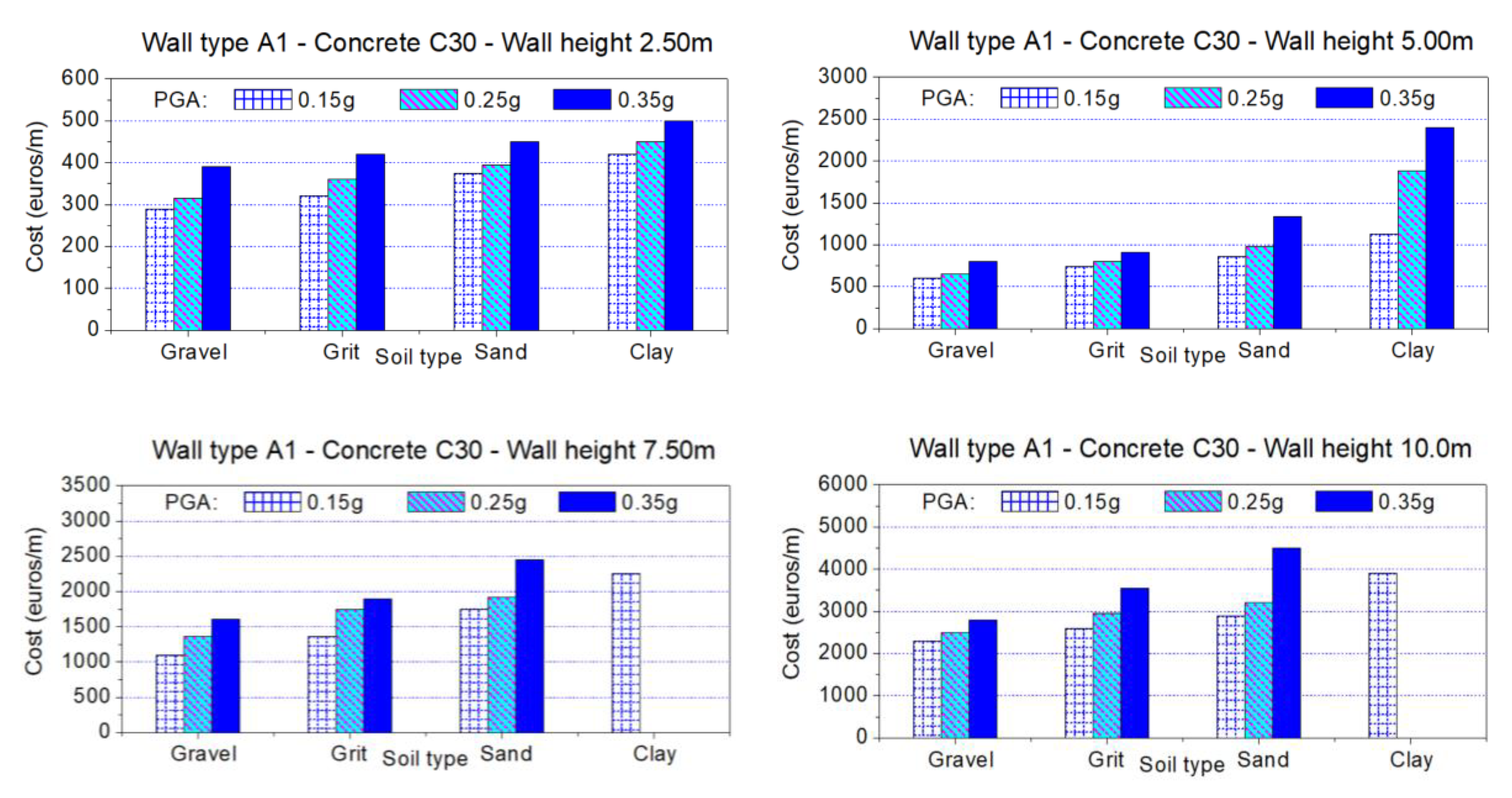
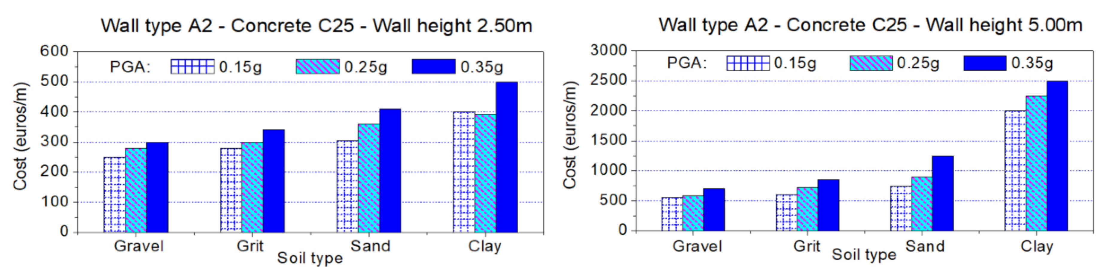
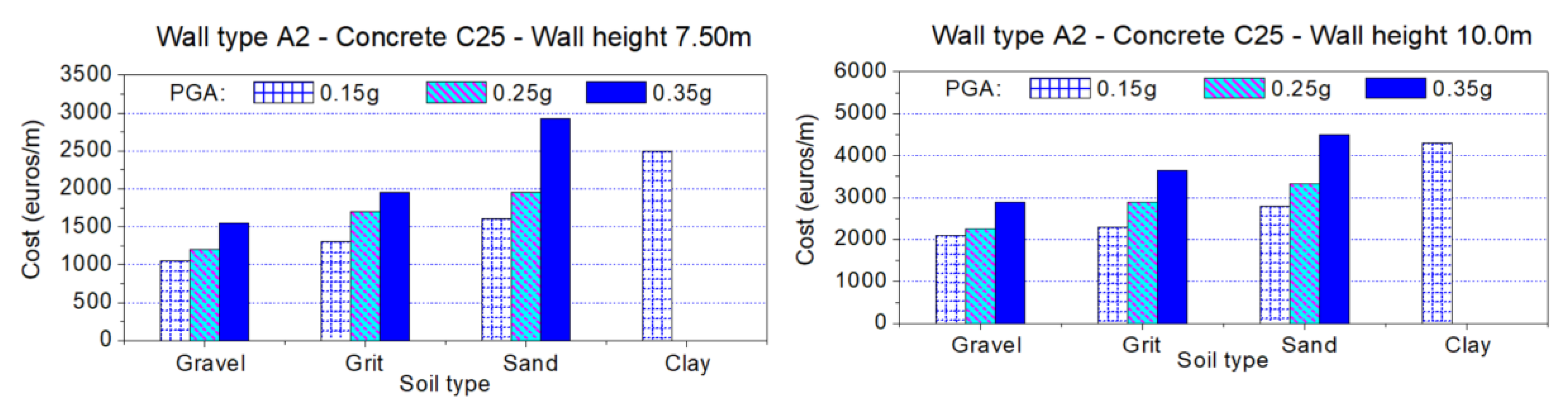
3. Analysis and Design Results

This section depicts the results from the aforementioned 384 cases of retaining walls. It should be noted that, in some cases, the results are not shown since the stability of the wall could not be achieved, i.e., for the combination of intense earthquakes (large PGA), very tall walls, and poor soil type. In these unfavorable cases, the adoption of reinforced concrete retaining walls like those shown in Figure 3 is not advisable, and other solutions should be considered, such as the usage of anchors.
The analysis results are shown in Figure 4, Figure 5, Figure 6, Figure 7, Figure 8, Figure 9, Figure 10 and Figure 11. These figures depict diagrams where each one shows the type of wall under consideration (A1, A2, B1, and B2), the concrete grade (C25 and C30), and the height of each wall (2.5 m, 5.0 m, 7.5 m, and 10 m). Thus, by selecting the above parameters and variables, it seems to be straightforward to draw significant conclusions, e.g., the effect of earthquake intensity on the total cost of the retaining wall and its dependence on wall geometry, soil type, etc. Each retaining wall was implemented, analyzed, and designed 30–40 times, using trial-and-error procedures to minimize the total cost and simultaneously to comply with the Eurocode provisions [14,15,16]. It should be mentioned that, in comparison to structures made by a single material (e.g., steel), member sections consisting of reinforced concrete have bigger dimensions. Furthermore, especially for the case of retaining walls, the minimization of dimensions should take into account both strength and stability criteria (e.g., sliding of the structure) while the “above-ground” constructions, such as building framed structures, were mainly designed using strength criteria only. Finally, the heuristic optimization applied here examined the optimum dimensions of the structural members using a “5 cm” rounding for the case of member length or thickness (5 cm, 10 cm, 15 cm, 20 cm, etc.). Despite the small incompatibility for the rigorous mathematical process of heuristic optimization, this consideration is used in everyday engineering practice and simplifies the whole procedure.

4. Discussion: Results and Implications

In this section, a brief discussion of results presented in Section 3 is provided. More specifically, the effects of various parameters on the total cost of retaining walls are critically discussed, and some useful conclusions about the optimal seismic design of these infrastructures are underlined. Furthermore, comparisons of these results with those of previous pertinent studies are also considered, while future research directions are highlighted.
Firstly, the influence of height of retaining wall on its total cost is examined. From Figure 4, Figure 5, Figure 6, Figure 7, Figure 8, Figure 9, Figure 10 and Figure 11, it is found that a higher total height leads to a higher total cost, independently of soil type and peak ground acceleration. Although this conclusion appears to be self-evident, Figure 4, Figure 5, Figure 6, Figure 7, Figure 8, Figure 9, Figure 10 and Figure 11 depict that, upon increasing the retaining wall height by a factor “x”, the increment of total cost is higher than “x”, e.g., upon doubling the height of the wall, the cost can be tripled or quadrupled.
Then, the influence of soil type on retaining walls total cost is investigated. From Figure 4, Figure 5, Figure 6, Figure 7, Figure 8, Figure 9, Figure 10 and Figure 11 , it is obvious that soil types with good enough mechanical properties lead to lower values of total cost, independently of peak ground acceleration and total height of walls. Specially, for the case of clay soils, the total cost of retaining wall appears to be very high, while it seems to be impractical to construct retaining walls with total height >7.5 m for the case of clay soils and medium or intense earthquakes, i.e., for PGA ≥0.25 g. For these reasons, all these cases are not shown in Figure 4, Figure 5, Figure 6, Figure 7, Figure 8, Figure 9, Figure 10 and Figure 11, where other construction techniques (e.g., anchored walls) are required. It should be mentioned that Jia et al. [36] found qualitatively similar results where soils with low level mechanical properties led to large dimensions for retaining wall elements, i.e., high total costs.
Furthermore, the influence of peak ground acceleration on the total cost of retaining walls is examined. From Figure 4, Figure 5, Figure 6, Figure 7, Figure 8, Figure 9, Figure 10 and Figure 11, it can be concluded that a higher seismic intensity leads to a higher total cost, independently of soil type and retaining wall total height. Although this finding appears to be self-evident, especially for the case of clay soils, the total cost of retaining walls appears to be huge, while it seems to be impractical to construct retaining walls with total height >7.5 m for the case of clay soils and medium or intense earthquakes, i.e., for PGA ≥0.25 g. As mentioned above, in these cases, other construction techniques (e.g., anchored walls) are required. It is worth noting that other previous studies, e.g., Bakr and Ahmad [37] or Nimbalkar et al. [38], found quite similar results where the increase of seismic intensity led to large dimensions for retaining wall elements, i.e., high total costs.
Finally, the influence of the compressive strength of concrete on the retaining walls total cost is critically discussed. From Figure 4, Figure 5, Figure 6, Figure 7, Figure 8, Figure 9, Figure 10 and Figure 11, it is observed that the compressive strength of concrete, i.e., the concrete grade, mildly affects the total cost of retaining walls, independently of soil type, peak ground acceleration, and total height of walls. This behavior has to do with the relatively small increase for the cost of the material from C25 to C30 and, simultaneously, the pertinent relatively small decrease for the dimensions of the structural members. Therefore, this study found that the influence of concrete grade on the total cost of retaining walls can be ignored.

5. Simplified Optimization of Reinforced Concrete Retaining Walls

In this section, a simplified optimization technique is investigated for the direct optimum design of reinforced concrete retaining walls. The direct evaluation of total cost can be achieved using Figure 4, Figure 5, Figure 6, Figure 7, Figure 8, Figure 9, Figure 10 and Figure 11. Examining these figures, it can be concluded that all the examined parameters, i.e., soil type, height of wall, type of wall, peak ground acceleration intensity, and concrete grade, affect more or less the optimum design and the minimization of cost. In this work, the following unique empirical expression is proposed for the evaluation of the optimal dimension of retaining wall members:
( a 1 + a 2 P G A + a 3 P G A 2 ) ( b 1 + b 2 q u + b 3 q u 2 ) ( c 1 + c 2 f c ) ( d 1 + d 2 H + d 3 H 2 ) ,
where a1, a2, and a3 are parameters related to the peak ground acceleration, PGA (in g; for example, 0.15 g), b1, b2, and b3 are parameters related to the soil type, through its compressive strength qu (in kPa, e.g., 300 kPa for sand, see also Table 1), c1 and c2 are parameters related to the uniaxial compressive strength of concrete, fc (in MPa, e.g., 25 ΜPa), and d1, d2, and d3 are parameters related to the total height of retaining wall, H (in m., e.g., 5.00 m).
The set of 11 parameters (a1, a2, a3, b1, b2, b3, c1, c2, d1, d2, and d3) can be determined using the least-square method of regression analysis from the databank of 384 retaining walls that were designed using the European codes [14,15,16]. Empirical Equation (3) can be adopted to evaluate the optimal dimension for the members of a retaining wall, i.e., footing length, footing section thickness, base thickness of the wall, top thickness of the wall, or the total cost. In the Appendix of this paper, Table A1 is provided to give the values for the set of 11 parameters examined above, for each member’s dimension. It should be mentioned that Equation (3) was one of the simplest equations which adequately described the numerical data following upward and downward concave curves, obtained using the Table Curve 3D program (Table Curve 3D v.5 © Systat Software, Inc., https://systatsoftware.com/) after examining about 8000 various mathematical equations. The criterion for the selection of Equation (3) has to do with its minimum absolute residual error using the Pearson VII limit, i.e., minimum sum of ln[√(1 + residual2)].

Application Example

Here, the optimum design of a reinforced concrete retaining wall with total height H = 6.0 m founded in a sand-type soil (compressive strength 280 kPa) made by concrete C20 is investigated. The expected peak ground acceleration in the construction area is 0.18 g. Applying Equation (1), the optimization results for this retaining wall are shown in Table 3. In parentheses, the results applying a trial-and-error procedure using BetonExpress analysis program [27] are shown to also find the optimum (minimum cost) design.
It is evident that the most economical case appears to be the retaining wall type A1. Furthermore, it is obvious that the results using the proposed empirical Equation (3) are very close to those from BetonExpress.
This can also be seen examining the whole set of 384 retaining walls. For example, Figure 12 depicts the optimal values of footing length and thickness (section height) for both procedures (Equation (1)) and BetonExpress design [27], where the agreement between them is obvious. Finally, the validity of Equation (1) can be demonstrated by the square of Pearson correlation coefficient, R2, between the optimal values from this empirical expression and BetonExpress [27], which is equal to 0.954 for footing length, 0.972 for footing thickness, 0.970 for wall thickness at its base, 0.969 for wall thickness at its top, and 0.952 for total cost.
All these values are very close to the unity, verifying the accuracy and applicability of Equation (3).

6. Conclusions

This work proposed new design aids for the optimum design of reinforced concrete retaining walls under the action of soil pressures and seismic loads. Four different profiles, named A1, A2, B1, and B2, were examined where the first dyad (type A) correspond to retaining walls with a relatively small back heel and active earth pressure was computed using Coulomb’s theory, while the second dyad (type B) has to do with retaining walls with an adequate back heel and active earth pressure computed using Rankine’s theory. Then, the analysis and design of 384 retaining walls was investigated, showing useful diagrams where various heights, soil types, and concrete grades were considered. Furthermore, empirical expressions for the direct evaluation of the optimum cost of walls was provided. A comprehensive analysis was conducted and the following conclusions can be drawn:
  • The stability of the tall reinforced concrete retaining walls (height 7.5 m or 10.0 m) founded on clay could not be achieved for the case of medium or intense earthquakes (PGA ≥0.25). In order to achieve stability, other solutions than those shown in Figure 3 should be considered, such as the usage of anchors.
  • Examining the case of soil with very good (gravel, grit) or good mechanical properties (sand), for low-height retaining walls (H ≤ 5.0 m) and for low or medium peak ground acceleration (PGA ≤ 0.25 g), retaining walls type B appear to be more economical in comparison with retaining walls type A. On the other hand, for intense peak ground acceleration (PGA = 0.35 g), type B is more expensive than type A for retaining walls.
  • Examining retaining walls founded in clay, the type B seems to be more expensive than type A, independently of the height and for any value of peak ground acceleration under consideration.
  • The type “2” of retaining walls with constant height footing is preferable as more economical for low-height retaining walls (≤5.00 m) and for soil with very good (gravel, grit) or good mechanical properties (sand) in comparison with retaining walls with angle-shaped footing. On the other hand, a retaining wall founded on clay should have, in any case, angle-shaped footing, independently of the wall’s height or seismic load intensity.
  • The concrete grade mildly affects the total cost of the retaining wall, where the small reduction of dimensions of wall and footing due to the usage of a higher grade of concrete is balanced by the slight increment of material cost.
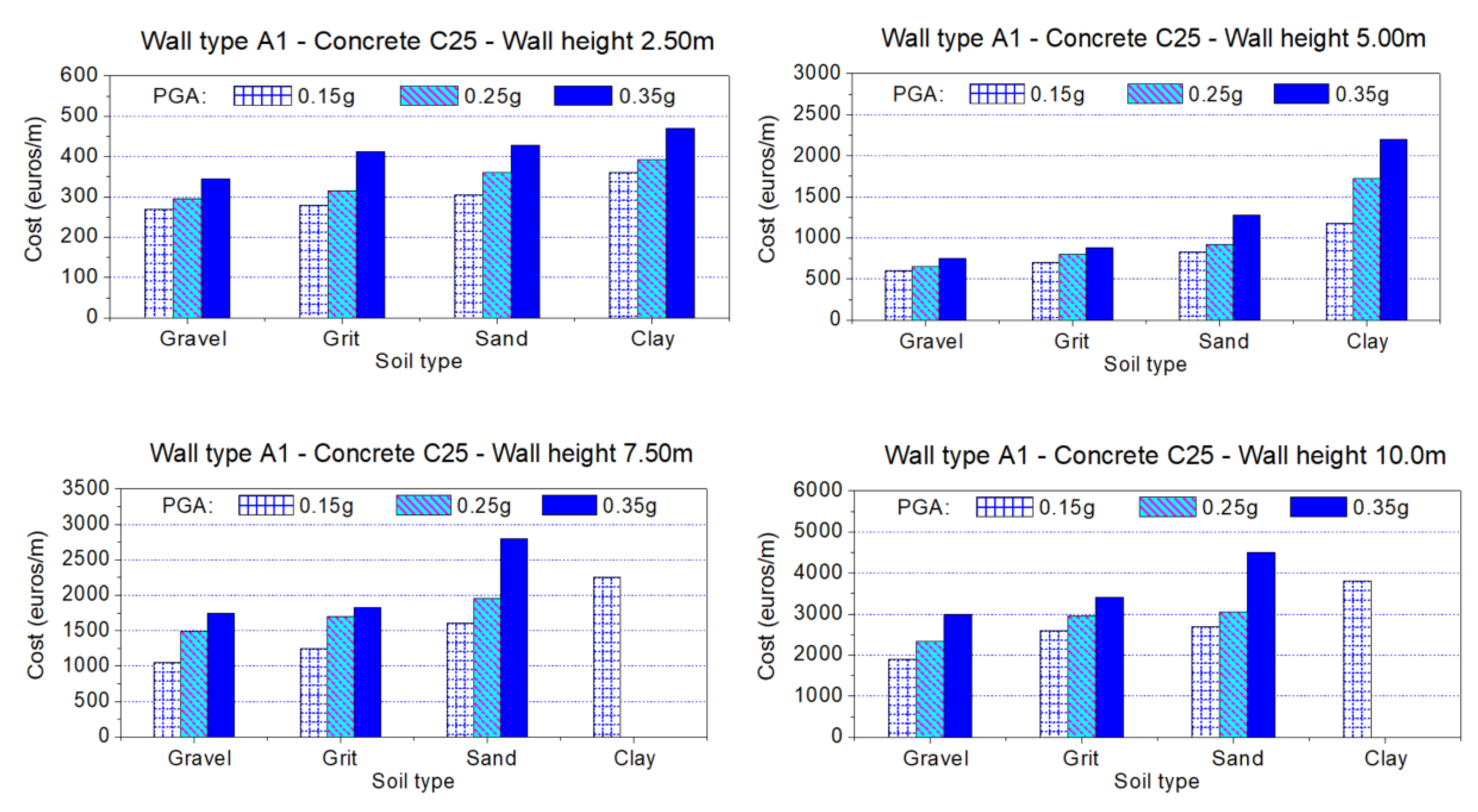
  • The peak ground acceleration strongly affects the total cost of the retaining wall especially in the case that the structure is founded on clay. In this case, the maximum height of the walls under consideration is 5.00 m.
  • The most critical parameters affecting the total cost of retaining structures are their height and the type of soil medium. In any case, the height of the wall nonlinearly increases the total cost, especially for the case where H ≥ 7.50 m. Furthermore, the total cost is increased as the mechanical properties of soil are degraded.
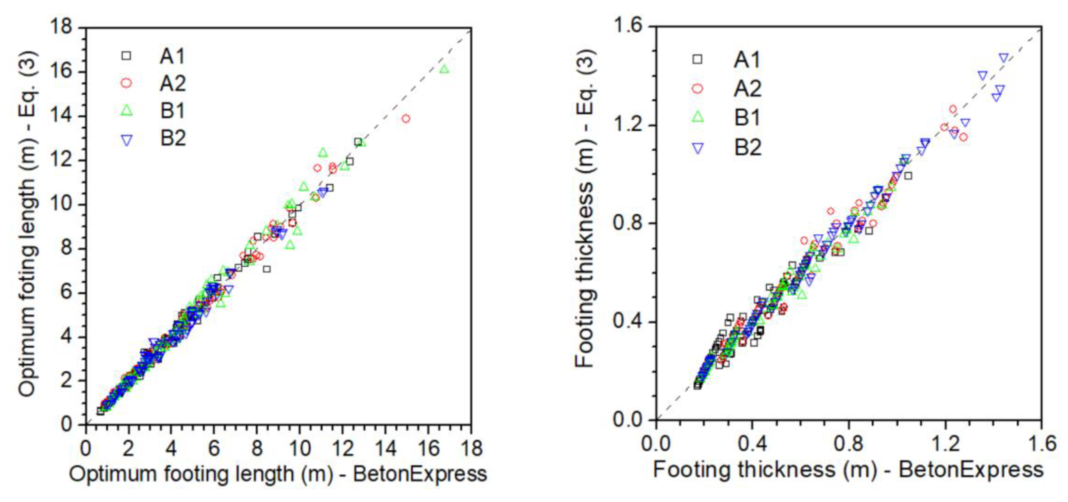
  • This study proposed a very simple yet effective empirical expression, Equation (3), to directly evaluate the optimum dimensions of reinforced concrete retaining walls subjected to soil pressure and seismic loads. This empirical expression is unique since it can be used for the optimal dimensioning of wall thickness at its base and top, footing length, and thickness, as well as the total cost. It was found that this empirical expression has sufficient accuracy and applicability.
  • The retaining walls examined here were designed using the force-based design method of European norms [16]. In an oncoming paper by the authors, the performance-based seismic design approach will be examined to directly fulfill the requirements for serviceability.

Author Contributions

Conceptualization, G.D.H.; methodology, F.K. and G.D.H.; formal analysis, F.K.; resources, F.K., M.T., and N.P.; data curation, F.K. and G.D.H.; writing—original draft preparation, all; writing—review and editing, F.K. and G.H.; visualization, F.K. All authors read and agreed to the published version of the manuscript.

Funding

This research received no external funding.

Conflicts of Interest

The authors declare no conflict of interest.

Appendix A

Table A1. Optimization parameters a1d3.
WallTypeParameter/DimensioningOptimization Parameters (a1d3)
a1a2a3b1b2b3c1c2d1d2d3
A1footing length8.6968 × 10−4−5.0644 × 10−31.8236 × 10−21.0333 × 10+3−2.73122.2996 × 10−31.7021 × 10−27.7216 × 10−4−5.9457 × 10+17.8489 × 10+1−8.8757 × 10⁻¹
footing thickness1.3681 × 10−42.4888 × 10−32.5779 × 10−33.0308 × 10+2−1.00671.1379 × 10−32.3711 × 10⁻²−2.9783 × 10−45.7139 × 10+13.7946 × 10+1−8.5380 × 10⁻¹
wall thickness—base8.0393 × 10−55.0548 × 10⁻³−1.1372 × 10−23.0246 × 10+2−4.5360 × 10−12.6752 × 10−42.4517 × 10⁻²−1.0836 × 10−41.0015 × 10+23.3953 × 10+13.3140 × 10⁻¹
wall thickness—top2.6460 × 10−47.8958 × 10⁻⁴−1.5416 × 10−34.6447 × 10+2−1.7126 × 10⁻¹−3.2764 × 10−43.0696 × 10−2−2.1535 × 10−47.0449 × 10+15.8047 × 10−18.9349 × 10−1
total cost8.5397 × 10−1−1.45838.1006−6.0027 × 10+21.5907−1.5143 × 10⁻³−7.1848 × 10⁻¹−6.0130 × 10⁻³−3.8649 × 10−15.9152 × 10−19.0146 × 10⁻²
A2footing length1.3333 × 10−1−2.1575 × 10−19.7996 × 10−1−1.5654 × 10+26.0029 × 10⁻¹−6.6377 × 10⁻⁴−3.3566 × 10⁻¹−2.2111 × 10⁻³−3.0301 × 10−15.2224 × 10−1−1.6849 × 10⁻³
footing thickness1.8082 × 10−2−2.0424 × 10−21.0175 × 10−1−1.5168 × 10+24.9570 × 10⁻¹−5.2943 × 10⁻⁴−1.5683 × 10−11.9658 × 10−31.50784.3992 × 10−13.3978 × 10⁻²
wall thickness—base1.2661 × 10−24.3167 × 10⁻²−1.8194 × 10⁻²−7.7596 × 10+15.4781 × 10−22.9755 × 10−5−1.1832 × 10−15.0544 × 10−42.3182−1.6513 × 10−14.1250 × 10−2
wall thickness—top5.7671 × 10−35.6805 × 10⁻²−4.5974 × 10⁻²−2.2966 × 10+1−7.3614 × 10−21.5163 × 10−4−1.5611 × 10−18.6747 × 10−43.4870−3.1496 × 10−16.1764 × 10−2
total cost3.8513 × 10−3−7.0226 × 10−33.5859 × 10−2−1.6133 × 10+56.1770 × 10+2−6.8278 × 10−17.5154 × 10−27.7879 × 10−46.9343−7.3161−1.7329
Β1footing length4.5986 × 10−4−5.6533 × 10−47.0530 × 10−37.9222 × 10+2−2.46722.3584 × 10−35.5091 × 10⁻²−9.1514 × 10−46.5469 × 10+17.1491 × 10+16.3607
footing thickness3.3044 × 10−4−1.1709 × 10−32.8988 × 10−35.8540 × 10+2−1.17029.7582 × 10−42.1325 × 10⁻²−3.4266 × 10−41.2895 × 10+22.8479 × 10+14.3132
wall thickness—base3.3341 × 10−41.3096 × 10⁻³−1.1874 × 10−31.4216 × 10+3−2.43171.8309 × 10−34.7186 × 10⁻³−6.5037 × 10−51.0204 × 10+29.28983.4690
wall thickness—top 9.1520 × 10−51.4467 × 10−3−2.2652 × 10−32.0180 × 10+3−8.6799 × 10⁻¹−1.1992 × 10−33.8174 × 10−3−4.8734 × 10−51.0645 × 10+21.7552 × 10+14.1711 × 10⁻¹
total cost2.9310 × 10−3−5.8828 × 10−34.2487 × 10−26.4767 × 10+4−1.9443 × 10+21.8416 × 10−17.0130 × 10−2−1.5442 × 10−36.5782 × 10+1−2.1732 × 10+11.3142 × 10+1
Β2footing length−1.5512 × 10⁻³−5.7629 × 10⁻³−2.5433 × 10⁻³−6.9217 × 10+32.7290 × 10+1−3.1357 × 10−21.9198 × 10−3−4.7276 × 10⁻⁶−2.9451 × 10+19.1583 × 10+1−7.9214 × 10⁻¹
footing thickness−9.8832 × 10−42.5018 × 10−3−9.3267 × 10⁻³−3.8783 × 10+31.3341 × 10+1−1.4841 × 10−23.1315 × 10−3−2.0978 × 10−51.9169 × 10+12.5268 × 10+19.5916 × 10⁻¹
wall thickness—base−1.0355 × 10⁻³−2.0164 × 10⁻³−4.5153 × 10⁻⁴−5.8504 × 10+31.6354 × 10+1−1.5664 × 10−21.2941 × 10−3−1.9225 × 10−61.5587 × 10+11.2931 × 10+12.8980 × 10⁻¹
wall thickness—top−6.0910 × 10⁻⁴−2.4521 × 10−31.6845 × 10−3−5.3867 × 10+31.1271 × 10+1−8.4126 × 10−31.2408 × 10−3−1.4738 × 10−63.1379 × 10+19.16662.2505 × 10−1
total cost3.3265 × 10−3−6.4403 × 10−33.5007 × 10−26.8619 × 10+4−2.6000 × 10+22.9120 × 10−12.3211 × 10−21.1070 × 10⁻⁴−1.1304 × 10+28.6826 × 10+11.2235 × 10+1

References

  1. Dembicki, E.; Chi, T. System analysis in calculation of cantilever retaining walls. Int. J. Numer. Anal. Methods Géomeéch. 1989, 13, 599–610. [Google Scholar] [CrossRef]
  2. Sarıbaş, A.; Erbatur, F. Optimization and Sensitivity of Retaining Structures. J. Geotech. Eng. 1996, 122, 649–656. [Google Scholar] [CrossRef]
  3. Rhomberg, E.J.; Street, W.M. Optimal design of retaining walls. J. Struct. Divis. ASCE 1981, 107, 992–1002. [Google Scholar]
  4. Sivakumar, B.; Munwar, B. Optimum design of cantilever retaining walls using target reliability approach. Int. J. Geomech. 2008, 8, 240–252. [Google Scholar] [CrossRef]
  5. Yepes, V.; Alcalá, J.; Perea, C.; González-Vidosa, F. A parametric study of optimum earth-retaining walls by simulated annealing. Eng. Struct. 2008, 30, 821–830. [Google Scholar] [CrossRef]
  6. Kaveh, A.; Behnam, A.F. Charged System Search Algorithm for the Optimum Cost Design of Reinforced Concrete Cantilever Retaining Walls. Arab. J. Sci. Eng. 2012, 38, 563–570. [Google Scholar] [CrossRef]
  7. Gandomi, A.H.; Kashani, A.R.; Roke, D.; Mousavi, M. Optimization of retaining wall design using recent swarm intelligence techniques. Eng. Struct. 2015, 103, 72–84. [Google Scholar] [CrossRef]
  8. Moayyeri, N.; Gharehbaghi, S.; Plevris, V. Cost-Based Optimum Design of Reinforced Concrete Retaining Walls Considering Different Methods of Bearing Capacity Computation. Mathematics 2019, 7, 1232. [Google Scholar] [CrossRef] [Green Version]
  9. Dagdeviren, U.; Kaymak, B. A regression-based approach for estimating preliminary dimensioning of reinforced concrete cantilever retaining walls. Struct. Multidiscip. Optim. 2020, 61, 1657–1675. [Google Scholar] [CrossRef]
  10. Lee, K.S.; Geem, Z.W.; Lee, S.-H.; Bae, K.-W. The harmony search heuristic algorithm for discrete structural optimization. Eng. Optim. 2005, 37, 663–684. [Google Scholar] [CrossRef]
  11. Li, L.; Huang, Z.; Liu, F.; Wu, Q. A heuristic particle swarm optimizer for optimization of pin connected structures. Comput. Struct. 2007, 85, 340–349. [Google Scholar] [CrossRef]
  12. Kaveh, A.; Talatahari, S. Optimum design of skeletal structures using imperialist competitive algorithm. Comput. Struct. 2010, 88, 1220–1229. [Google Scholar] [CrossRef]
  13. Minoglou, M.K.; Hatzigeorgiou, G.; Papagiannopoulos, G. Heuristic optimization of cylindrical thin-walled steel tanks under seismic loads. Thin-Walled Struct. 2013, 64, 50–59. [Google Scholar] [CrossRef]
  14. European Committee for Standardization. EN 1992-1-1 Eurocode 2: Design of Concrete Structures—Part 1-1: General Rules and Rules for Buildings; CEN: Brussels, Belgium, 2004. [Google Scholar]
  15. European Committee for Standardization. EN 1997-1. Eurocode 7: Geotechnical Design-Part 1: General Rules; CEN: Brussels, Belgium, 2004. [Google Scholar]
  16. European Committee for Standardization. EN 1998-5. Eurocode 8: Design of Structures for Earthquake Resistance—Part 5: Foundations, Retaining Structures and Geotechnical Aspects; CEN: Brussels, Belgium, 2004. [Google Scholar]
  17. Okabe, S. General theory on earth pressure and seismic stability of retaining wall and dam. Jpn. Soc. Civ. Eng. 1924, 12, 34–41. [Google Scholar]
  18. Mononobe, N. Earthquake proof construction of masonry dams. In Proceedings of the World Engineering Congress, Tokyo, Japan, 28 October–5 November 1929; pp. 275–293. [Google Scholar]
  19. Terzaghi, K.; Peck, R.B.; Mesri, G. Soil Mechanics in Engineering Practice; John Wiley & Sons: Hoboken, NJ, USA, 1996. [Google Scholar]
  20. Mylonakis, G.; Kloukinas, P.; Papantonopoulos, C. An alternative to the Mononobe—Okabe equations for seismic earth pressures. Soil Dyn. Earthq. Eng. 2007, 27, 957–969. [Google Scholar] [CrossRef]
  21. Javanmard, M.; Angha, A.R. Seismic Behavior of Gravity Retaining Walls. J. Geotech. Geoenviron. Eng. 2010, 105, 2263–2270. [Google Scholar]
  22. Callisto, L.; Soccodato, F.M. Seismic Design of Flexible Cantilevered Retaining Walls. J. Geotech. Geoenviron. Eng. 2010, 136, 344–354. [Google Scholar] [CrossRef]
  23. Callisto, L. On the seismic design of displacing earth retaining systems. In Earthquake Geotechnical Engineering for Protection and Development of Environment and Constructions, Proceedings of the 7th International Conference on Earthquake Geotechnical Engineering (ICEGE 2019), Rome, Italy, 17–20 June 2019; CRC Press: Boca Raton, FL, USA, 2019; p. 239. [Google Scholar]
  24. Azarafza, M.; Feizi-Derakhshi, M.-R.; Azarafza, M. Computer modeling of crack propagation in concrete retaining walls: A case study. Comput. Concr. 2017, 19, 509–514. [Google Scholar] [CrossRef]
  25. Ren, F.; Zhang, F.; Wang, G.; Zhao, Q.; Xu, C. Dynamic assessment of saturated reinforced-soil retaining wall. Comput. Geotech. 2018, 95, 211–230. [Google Scholar] [CrossRef]
  26. Beskou, N.D.; Papagiannopoulos, G.; Chassiakos, A.P. Seismic analysis of rigid walls retaining a cross-anisotropic poroelastic soil layer over bedrock. Soil Dyn. Earthq. Eng. 2018, 114, 615–624. [Google Scholar] [CrossRef]
  27. Runet. BETON-EXPRESS: Software for Designing Structural Elements of Reinforced Concrete. Available online: http://www.runet-software.com/BETONexpress.htm (accessed on 26 October 2015).
  28. Clough, G.W.; Duncan, J.M. Earth Pressures. In Foundation Engineering Handbook; Fang, H.Y., Ed.; Springer: Boston, MA, USA, 1991; pp. 223–235. [Google Scholar]
  29. Yap, S.P.; Salman, F.A.; Shirazi, S.M. Comparative study of different theories on active earth pressure. J. Central South Univ. 2012, 19, 2933–2939. [Google Scholar] [CrossRef]
  30. Chen, W.F.; Liu, X.L. Limit Analysis in Soil Mechanics; Elsevier: Amsterdam, The Netherlands, 1990. [Google Scholar]
  31. Bolton, M.D.; Steedman, R.S. Modelling the seismic resistance of retaining structures. In Proceedings of the 11th Int. Conference on Soil Mechanics and Foundation Engineering, San Francisco, CA, USA, 12–16 August 1985; Volume IV, pp. 1845–1848. [Google Scholar]
  32. Elms, D.G.; Richards, R., Jr. Seismic design of retaining walls. In Proceedings of the Conference on Design and Performance of Earth Retaining Structures, Ithaca, NY, USA, 18–21 June 1990; ASCE Geo-Special Publication No. 25. pp. 854–871. [Google Scholar]
  33. ASTM. Standard Test Method for Unconfined Compressive Strength of Cohesive Soils; ASTM: West Conshohoken, PA, USA, 2013. [Google Scholar]
  34. Santoni, R.L.; Tingle, J.S.; Webster, S.L. Engineering Properties of Sand-Fiber Mixtures for Road Construction. J. Geotech. Geoenviron. Eng. 2001, 127, 258–268. [Google Scholar] [CrossRef]
  35. Bowles, L.E. Foundation Analysis and Design, 5th ed.; McGraw-Hill: Singapore, 1997. [Google Scholar]
  36. Liang, J.; He, S.; Li, N.; Wang, W.; Yao, K. Stability of Reinforced Retaining Wall under Seismic Loads. Appl. Sci. 2019, 9, 2175. [Google Scholar] [CrossRef] [Green Version]
  37. Bakr, J.; Ahmad, S.M. A finite element performance-based approach to correlate movement of a rigid retaining wall with seismic earth pressure. Soil Dyn. Earthq. Eng. 2018, 114, 460–479. [Google Scholar] [CrossRef] [Green Version]
  38. Nimbalkar, S.; Pain, A.; Ahmad, S.M.; Chen, Q.S. Stability Assessment of Earth Retaining Structures under Static and Seismic Conditions. Infrastructures 2019, 4, 15. [Google Scholar] [CrossRef] [Green Version]
Figure 1. Stability checks for reinforced concrete retaining walls.
Infrastructures 05 00046 g001
Figure 2. Stability checks for reinforced concrete retaining walls.
Infrastructures 05 00046 g002
Figure 3. Reinforced concrete retaining walls examined in this study (types A1, A2, B1, and B2) and a typical example of a 2.5-m-height A1-type retaining wall (dimensions in meters).
Infrastructures 05 00046 g003
Figure 4. Cost of retaining walls type A1 made by reinforced concrete C25.
Infrastructures 05 00046 g004
Figure 5. Cost of retaining walls type A1 made by reinforced concrete C30.
Infrastructures 05 00046 g005
Figure 6. Cost of retaining walls type A2 made by reinforced concrete C25.
Infrastructures 05 00046 g006aInfrastructures 05 00046 g006b
Figure 7. Cost of retaining walls type A2 made by reinforced concrete C30.
Infrastructures 05 00046 g007
Figure 8. Cost of retaining walls type B1 made by reinforced concrete C25.
Infrastructures 05 00046 g008
Figure 9. Cost of retaining walls type B1 made by reinforced concrete C30.
Infrastructures 05 00046 g009
Figure 10. Cost of retaining walls type B2 made by reinforced concrete C25.
Infrastructures 05 00046 g010
Figure 11. Cost of retaining walls type B2 made by reinforced concrete C30.
Infrastructures 05 00046 g011
Figure 12. Optimum dimensions for retaining wall footing: Equation (3) vs. BetonExpress [27].
Infrastructures 05 00046 g012
Table 1. Mechanical properties of soil materials.
Soil TypeDry Density γd (kN/m3)Density γ (kN/m3)Friction Angle φoCohesion c (kPa)Compressive Strength (kPa)
Gravel16.020.045.00.0500.0
Grit16.020.035.00.0400.0
Sand15.019.025.00.0300.0
Clay20.021.020.020.0150.0
Table 2. Material/labor costs for reinforced concrete retaining walls.
Work/MaterialQuantityCosts
Excavation (including transport of excavated products)m3Gravel: 11.00
Grit: 10.60
Sand: 10.00
Clay: 9.80
Earth fill-in (including transport)m39.50
Supply, transport on site, laying and compaction of concrete using a pump or tower crane€/m3C25/30: 110.00
C30/37: 125.00
Supply, transport on site, setting of reinforced concrete bars€/kg2.40
Molded foundation formwork—placement and removal€/m232.50
Molded wall formwork—placement and removal€/m234.80
Rebar spacers€/m23.50
Concrete maintenance€/m24.00
Table 3. Optimization results.
ParameterWall A1Wall A2Wall B1Wall B2
Footing length3.04 m (3.00 m)5.38 m (5.40 m)4.47 m (4.50 m)4.17 m (4.15 m)
Footing thickness0.33 m (0.35 m)0.61 m (0.60 m)0.47 m (0.45 m)0.61 m (0.60 m)
Base thickness0.86 m (0.85 m)0.36 m (0.35 m)0.45 m (0.45 m)0.46 m (0.45 m)
Top thickness0.39 m (0.40 m)0.24 m (0.25 m)0.30 m (0.30 m)0.34 m (0.35 m)
Total cost1256 €/m (1265 €/m)1416 €/m (1425 €/m)1290 €/m (1290 €/m)1334 €/m (1330 €/m)

