Evaluation of Residual Stress Relaxation in a Rolled Joint by Neutron Diffraction


1
Comprehensive Research Organization for Science and Society, Tokai, Ibaraki 319-1106, Japan
2
Canadian Neutron Beam Centre, National Research Council, Chalk River, ON K0J 1J0, Canada
3
Canadian Neutron Beam Centre, Canadian Nuclear Laboratories, Chalk River, ON K0J 1J0, Canada
4
Materials Sciences Research Center, Japan Atomic Energy Agency, Tokai, Ibaraki 319-1195, Japan
*
Author to whom correspondence should be addressed.
Quantum Beam Sci. 2018, 2(4), 21; https://0-doi-org.brum.beds.ac.uk/10.3390/qubs2040021
Submission received: 27 March 2018
/
Revised: 1 October 2018
/
Accepted: 2 October 2018
/
Published: 12 October 2018
(This article belongs to the Special Issue Strain, Stress and Texture Analysis with Quantum Beams)
Abstract
:The rolled joint of a pressure tube, consisting of three axial symmetric parts, modified SUS403 stainless steel as an inner extension, Zr–2.5Nb as the pressure tube and an Inconel-718 outer sleeve has been examined by neutron diffraction for residual stresses. It was heat treated to 350 °C for 30, 130 and 635 h to simulate thermal aging over the lifetime of an advanced thermal reactor respectively for 1, 5 and 30 years at an operating temperature of 288 °C. The crystallographic texture has been investigated from cylindric disks cut from the heat treated Zr–2.5Nb pressure tube to determine the proper sample-orientation-dependent hkl reflections for reliable residual strain measurements. Corresponding in situ tensile deformation was carried out to obtain the necessary diffraction elastic constants for the residual stress evaluation. Three-dimensional crystal lattice strains at various locations in the rolled joint before and after the aging treatments for various times were non-destructively measured by neutron diffraction and the residual stress distribution in the rolled joint was evaluated by using the Kröner elastic model and the generalized Hooke’s law. In the crimp region of the rolled joint, it was found that the aging treatment had a much weaker effect on the residual stresses in the Inconel outer sleeve and the modified SUS403 stainless steel extension. In the non-aged Zr–2.5Nb pressure tube, the highest residual stresses were found near its interface with the modified SUS430 stainless steel extension. In the crimp region of the Zr–2.5Nb pressure tube near its interface with the modified SUS430 stainless steel, the average compressive axial stress was −440 MPa, having no evident change during the long-time aging. In the Zr–2.5Nb pressure tube outside closest to the crimp region, the tensile axial and hoop stresses were relieved during the 30 h of aging. The hoop stresses in the crimp region evolved from an average tensile stress of 80 MPa to an average compressive stress of 230 MPa after the 635 h of aging, suggesting that the rolled joint had a good long-term sealing ability against leakage of high temperature water. In the Zr–2.5Nb pressure tube close to the reactor core and far away from the modified SUS403 stainless steel extension, the residual stresses near the inside surface of the pressure tube were almost zero, helping to keep a good neutron irradiation resistance.
1. Introduction
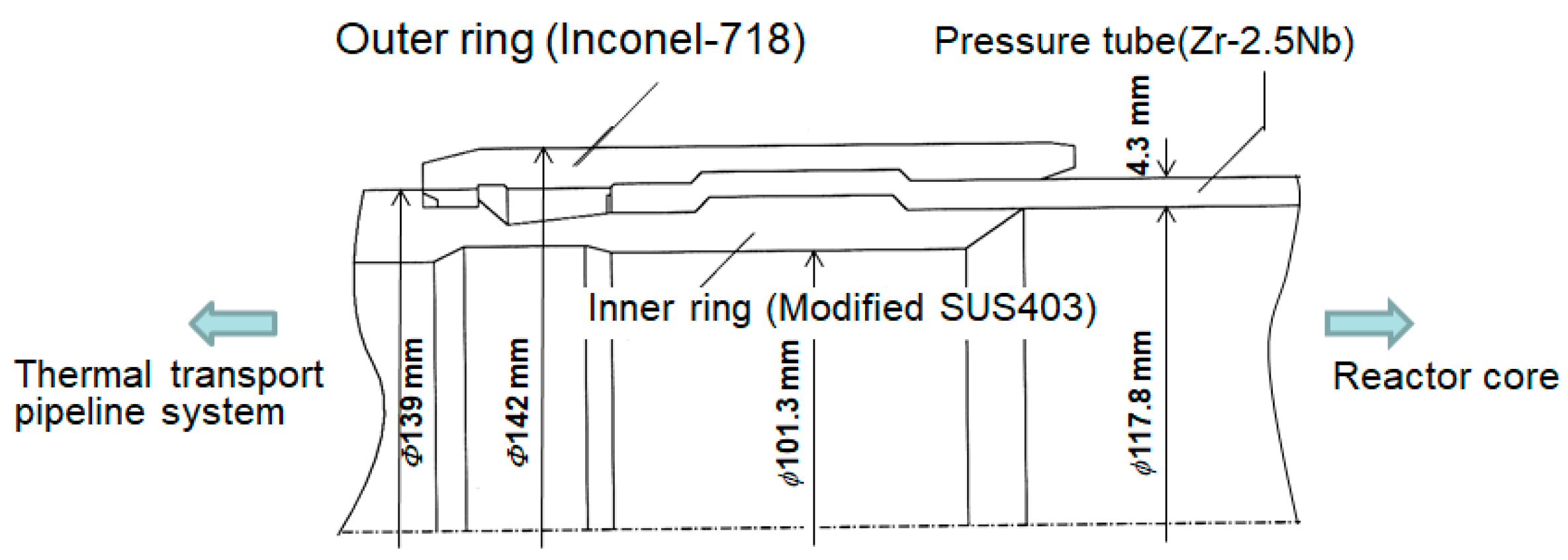
A little similar to the Canada Deuterium Uranium (CANDU) pressurized heavy-water reactor, the advanced thermal reactor (ATR) is a heavy-water moderated, boiling light-water cooled pressure-tube type thermal reactor, which has been developed to realize 600 MW of electric power output per reactor [1,2]. Since a pressure tube made from a zirconium alloy cannot be well welded with a stainless steel pipe, they are mechanically joined together by a rolled-joining process. The upper cross-sectional structure of the pressure tube rolled joint is shown in Figure 1. The Zr–2.5Nb pressure tube is sandwiched between the inner ring (pressure extension tube) made of modified SUS403 stainless steel and the outer ring made of Inconel-718. At the rolled joint portion, the internal surface of the outer ring and the external surface of the inner extension tube have an uneven profile configuration. After rolled-joining the three alloy components, the Zr–2.5Nb pressure tube is deformed to make its shape fit the surface profiles of the outer ring and the inner extension tube and the evidently large residual internal pressure takes place around the uneven structure and nearby. While the rolled joint maintains a water/steam tight seal between the Zr–2.5Nb pressure tube and the modified SUS403 stainless steel extension tube due to the as-rolled local plastic deformation at the uneven portion, consequently, a reasonable three-dimensional residual stress field distribution around the uneven structure obtained from the rolled-joining process is necessary to be well kept. This tight fitting of the rolled joints is required to connect the Zr–2.5Nb pressure tube to the balanced heat transport pipeline system that carries the hot (288 °C), high-pressure (7 MPa) water from the nuclear reactor core to the steam generators and back. It is therefore very important to evaluate the relaxation resistance of the residual stress in the pressure tube in order to guarantee the long-time structure integrity, especially for preventing a high-pressure water/stream leakage, over the target 30-year service lifetime of ATR pressure tube systems.
The neutron diffraction technique is well known as the available unique method with high reliability to non-destructively determine residual stresses inside thick components because of the deep penetrability of a neutron beam. This diffraction technique has been applied to stress distribution measurements at the weld metal and the fatigue crack tip in a compact tension (CT) specimen under loaded and unloaded conditions [3,4,5,6,7]. Elastic constants are essential to convert residual strains to residual stresses. Since the elastic constants depend on diffraction planes, Hayashi et al. [8] investigated this dependency for ferritic steel and found that the Kröner elastic model [9] can be employed to account for the diffraction plane dependency of the elastic constants and proposed a calculation method for elastic constants using Young’s modulus ratio between the investigated polycrystalline material and the single crystal [8]. Hayashi et al. also examined the spatial distribution of residual stresses in a socket welded joint and a 4-inch butt welded pipe joint and found a good agreement between the neutron diffraction method and the X-ray diffraction or the strain gauge method [10,11]. The inherent strain analysis and the finite element analysis showed that the residual stress distributions calculated agree well with those measured by the neutron diffraction method except at the stress concentration region [12].
Since the zirconium alloy tubes are produced using an extrusion process, an extrusion deformation texture is formed [13,14]. Accordingly, the effect of the texture of the pressure tube needs to be taken into account during the quantitative residual stress evaluation. While the texture and residual stresses of the zirconium alloy tube used in the CANDU reactor have been measured by neutron diffraction [14,15], the zirconium alloy pressure tube for the Japanese ATR [1,2] has not been measured yet. In this study, the crystallographic texture and the diffraction elastic constants of the heat-treated Zr–2.5Nb pressure tube together with the relaxation behavior of the residual stresses were evaluated by neutron diffraction.
2. Experimental Procedures
2.1. Texture Measurements
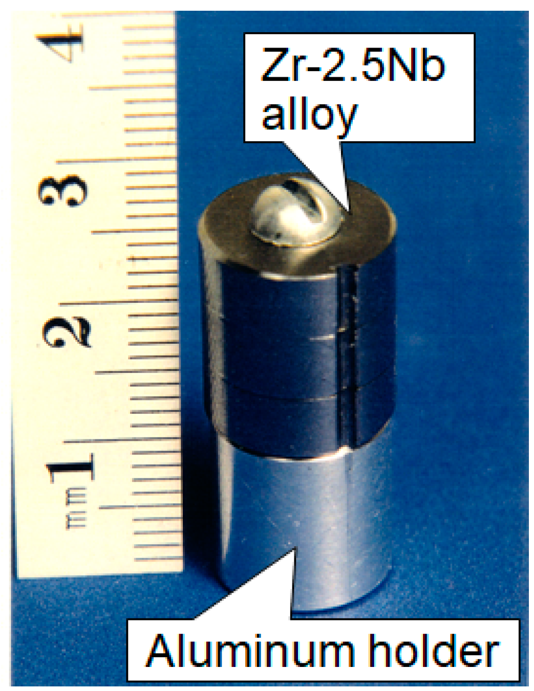
The texture specimen was prepared by spark-cutting to form disks 12 mm in diameter and heights equal to the thickness of the Zr–2.5Nb pressure tube. Three discs were stacked on an aluminum base to form a cylinder. The discs were held together with an aluminum screw, which passed through the cylinder axis and was threaded into the aluminum base. Neutron-transparent aluminum was chosen as a fastener of the zirconium alloy discs because the zirconium and the aluminum produce diffraction peaks that are easily distinguished. The relative alignments of the discs, and their orientations with respect to the symmetry axes of the pressure tube were marked and were reproducible to a precision of better than ±0.3 degree. A typical Zr–2.5Nb sample for texture measurement [16] is shown in Figure 2.
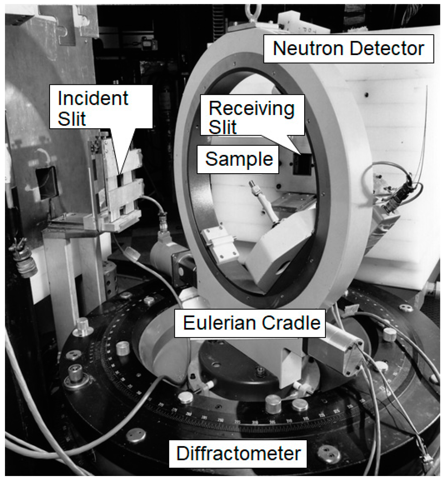
The texture was measured using the E3 neutron diffractometer located at the National Research Universal (NRU) nuclear reactor, at the Canadian Neutron Beam Centre, Chalk River, Ontario, Canada. The incident and scattered beams had square cross-sections 50 mm wide and 50 mm high. The angular divergence of these beams was restricted by Soller slit collimators to be 0.4° in the horizontal plane of diffraction. The wavelength of the neutron beam was 0.17 nm. The neutron detector was placed at scattering angles that corresponded to the observed maxima of neutron diffraction peaks from the (100), (002), (101), (102), and (110) planes of the hexagonal close-packed lattice of the zirconium alloy. For each (hkl) plane, the textured specimen was scanned through a complete hemisphere of orientations with a computer-controlled Eulerian cradle. The instrument setup for neutron diffraction texture measurements [16] is shown in Figure 3.
At each specimen orientation, the diffraction peak profile was measured. The incident and diffracted neutron beams intersected to form a volume much larger than the volume of the texture specimen. Thus, at every orientation, the texture specimen was completely bathed in the neutron beam. Therefore, the measured diffraction peak intensity at each orientation was directly proportional to the volume fraction of crystallites whose plane-normal directions were parallel to the scattering vector. Through-thickness gradients of texture that might exist in a pressure tube cannot be revealed by this bulk measurement, which yields an average of the texture in the specimen volume.
2.2. Elastic Constants
The tensile testing specimen was cut parallel to the longitudinal direction of the original Zr–2.5Nb pressure tube. The gauge length was 75 mm long and the cross-sectional area was 19.8 mm2. An extensometer was affixed to the specimen to determine the bulk averaged strain at the same time as the neutron diffraction measurements of (hkl)-dependent lattice strains were performed. The gauge length of the extensometer was 8 mm.
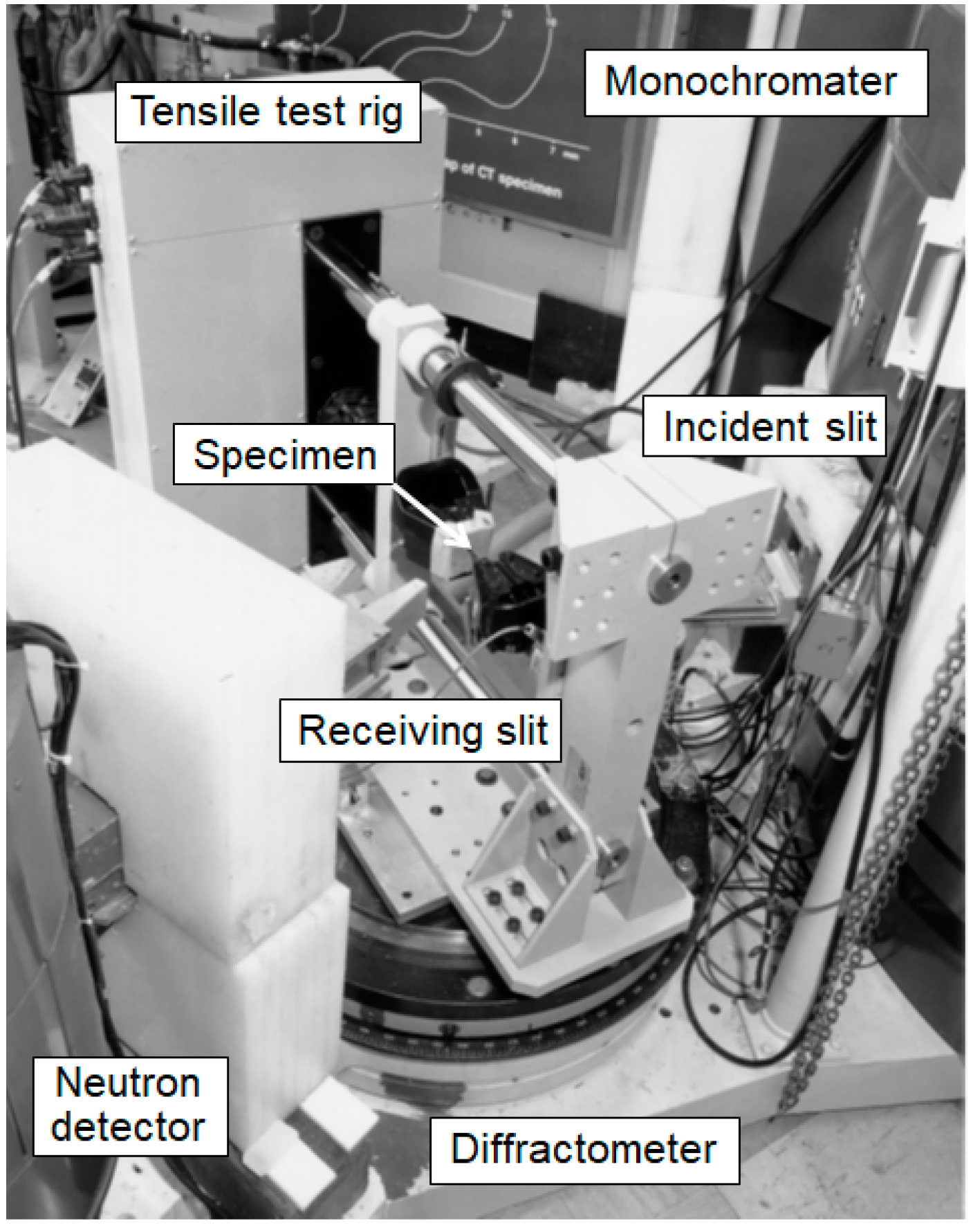
An automated load frame was installed on the L3 neutron diffractometer, located at the NRU nuclear reactor. The setup of the tensile test rig on the diffractometer [8] is shown in Figure 4.
The incident neutron beam was shaped by a slit mask, 30 mm high and 20 mm wide. The horizontal angular divergence was restricted to be about 0.4° by Soller slit collimators in the incident and diffracted beams. Diffraction peaks were obtained by scanning a single 3He detector to count neutrons as a function of scattering angle.
Uniaxial tensile loads were applied to the specimen with a precision of ±0.01 kN. The range of the applied load was approximately 0 to 200 MPa, well below the 0.2% offset yield stress in order to analyze the diffraction elastic constants. The load frame was oriented with its tensile axis parallel to the scattering vector for measurements of strain that were parallel to the applied stress, from which Young’s modulus was deduced. To determine the diffraction plane-dependent Young’s moduli, the diffraction peaks of 100, 002, and 101 reflections were acquired at each applied load. The load frame was aligned with its vertical tensile axis for measurements of strain perpendicular to the applied stress, from which Poisson’s ratio was deduced. For the measurements needed to determine the diffraction plane-dependent Poisson’s ratios, the diffraction peaks of 100, 002, 101, and 110 reflections were acquired at each applied load.
Each diffraction peak was fitted with a Gaussian function plus a linear background to determine the mean scattering angle, 2θ, with a typical uncertainty of ±0.004°. The stress-free lattice spacing for in situ strain analysis was assumed to be the values measured with the load set to zero. The typical uncertainty error in individual strain measurements was ±0.8 × 10⁻⁴. Young’s modulus and Poisson’s ratio were determined from the slopes of the lines that best fit the data of lattice strain versus applied stress.
2.3. Residual Stress Measurements
Neutron diffraction is a method for measuring the spacing, d, between the neighboring atomic planes of a crystal lattice. A neutron beam with a known wave length λ, is diffracted from its incident direction by a scattering angle 2θ according to Bragg’s law,
A profile of neutron counts versus 2θ is obtained and fit to a Gaussian function to obtain the mean scattering angle with a high precision of ±0.003° in 2θ. In most engineering materials, d ranges from 0.1 nm to 0.3 nm. They are determined by Equation (1) to a precision of about ±1 × 10⁻⁵ nm.
λ = 2d sinθ
Elastic strain, ε, is determined by comparing the measured value of d to the value measured in a suitable stress-free reference (d0), i.e., from the peak shift of the scattering angle, Δθ.
ε = (d/d0 − 1) = −cotθ0 Δθ
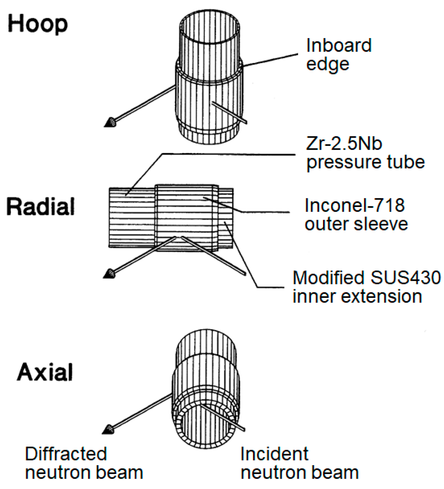
Strain components are measured in the scattering plane in a direction perpendicular to the bisection between the incident and the diffracted neutron beams. To obtain values of strain in the axial (A), radial (R) and hoop (H) directions of the cylindrical component of the upper rolled joint, as shown in Figure 5, the component must be reoriented to place this bisector in the required direction.
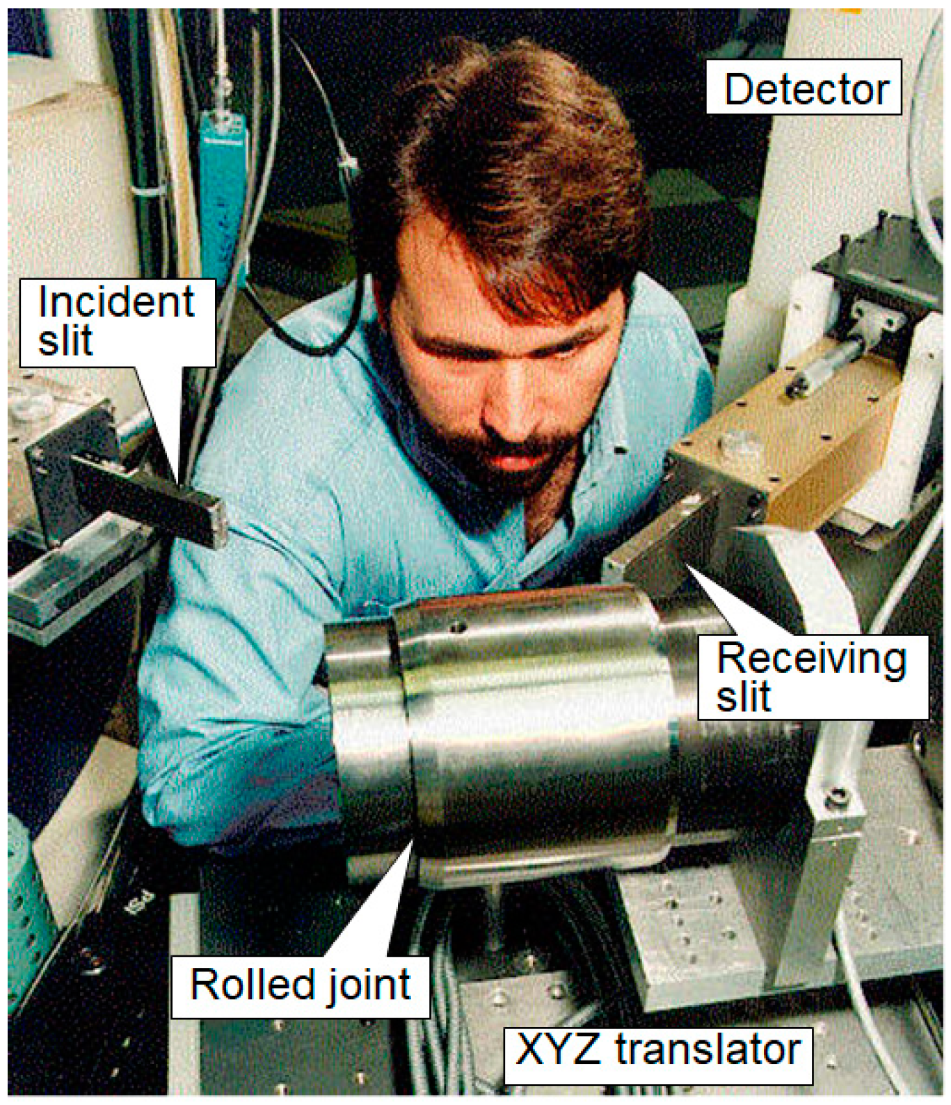
Diffraction from the (113) crystal plane of a germanium monochromator provided a neutron wavelength of 0.261364 nm incident to the sample. The incident and diffracted beams were shaped by slits with neutron-absorbing cadmium masks and the dimensions of nominal gauge volumes for strain measurements were defined by the intersection of these neutron beams as follows: For axial and radial strains, 1 × 1 × 10 mm3, with the 10 mm direction tangent to the curved surface; for the hoop strain, 1 × 1 × 5 mm3, with the 5 mm direction parallel to the tube axis. A computer-controlled XYZ translator was employed here to move the selected positions of the rolled joint to the sample center of the neutron diffractometer during the strain scanning. Such measurement positions were selected to ensure a completely filled gauge volume. Figure 6 shows the rolled joint on the L3 diffractometer used during the residual strain measurement.
All the three components of the three-dimensional lattice strains were evaluated from the shifts in the diffraction peaks of the 111 reflection for the Inconel-718 alloy and the diffraction peaks of the 110 reflection of the modified SUS403 stainless steel material, relative to the corresponding peaks of stress-free monolithic samples. Due to the significant texture of the Zr–2.5Nb pressure tube, the choice of diffracting planes depended on the tube orientation. Strains along the axial and hoop directions, and , were measured using the 002 reflection, while the 100 reflection was employed to measure the radial strain, . Considering the macro residual stresses belonged to the elastic stresses, the radial strain using the 002 reflection was estimated here from the radial strain using the 100 reflection by assuming the following linear elastic relationship dependent on various diffraction planes obtained from the in situ tensile deformation [16,17,18].
After three-dimensional strain measurements at each location, residual stresses were calculated through a generalized Hooke’s law,
where the hkl-dependent elastic constants are, Ehkl, Young’s modulus and, νhkl, Poisson’s ratio, and the H, R and A subscripts indicate the component directionality of the strains and stresses. The radial, axial and hoop components of stress, σR, σA and σH, were obtained by cyclic permutation of the indices in Equation (4).
It is well known that the diffraction elastic constants for cubic materials can be reliably obtained by a calculation based on single crystal elastic constants and the Kröner model of elasticity [7,8]. Therefore, the stresses in the modified SUS403 stainless steel and Inconel-718 components of the rolled joint will be determined from measured strains, with calculated values of the diffraction elastic constants in Table 1. For the heat-treated Zr–2.5Nb, in situ tensile deformation neutron measurements have been carried out to obtain the diffraction elastic constants [16]. These measured diffraction elastic constants will be applied in Equation (4) to determine the residual stresses from crystal lattice strains in the Zr–2.5Nb alloy of the rolled joint.
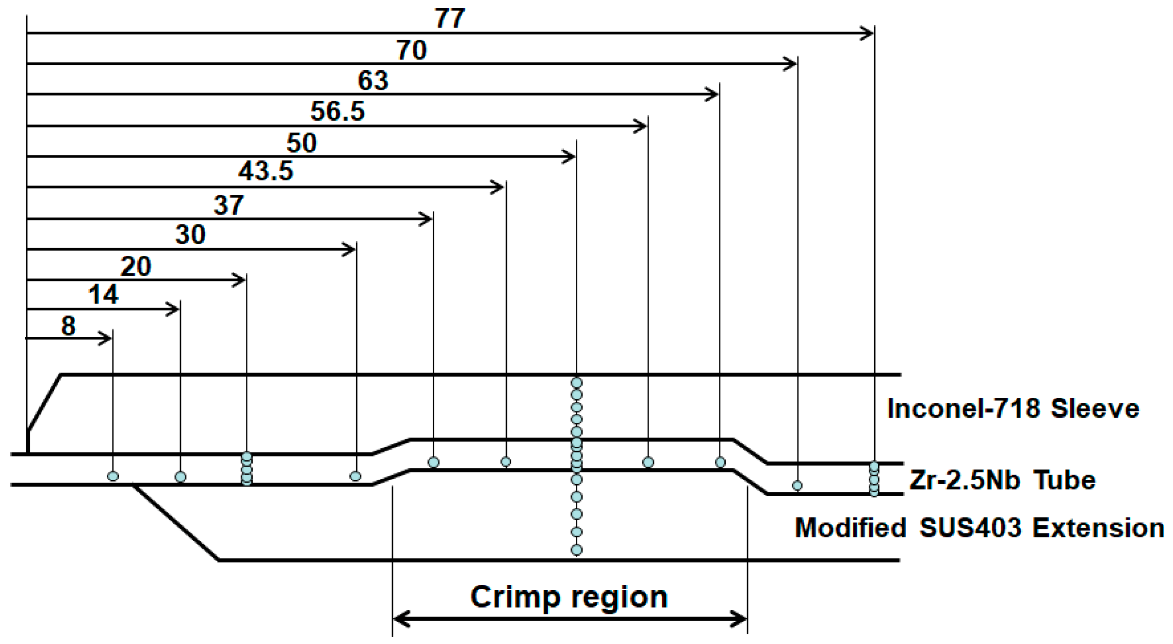
Figure 7 shows the selected positions, dimensions, materials and reference positions for the residual stress measurements. The inner extension tube of the modified SUS403 martensitic stainless steel was with a body-centered cubic crystal structure. The outer ring sleeve of the Inconel-718 nickel-based alloy was with a face-centered cubic crystal structure. Crimped alloy material between the extension and the outer sleeve was a heat-treated Zr–2.5Nb pressure tube, with a hexagonal close-packed crystal structure. The end of the Inconel-718 ring that was closest to the core of the reactor is denoted as the inboard or zero-position edge along the axial direction and the inner surface of the modified SUS403 stainless steel extension was the zero-position edge along the radial direction (Figure 7). Four specimens were provided for each of the monolithic materials: Zr–2.5Nb, Inconel-718 and modified SUS403 to serve as stress-free references for the determination of d0, which is required to calculate the strain by Equation (2). Each specimen was a rectangular prism with dimensions of 4 × 4 × 20 mm3. The specimens accompanied the rolled joint through the various aging treatments so that when all the measurements were completed, there was a reference for each material at each stage of the aging treatment.
2.4. Heat Treatments
Heat treatment of the rolled joint of the pressure tube to simulate the actual nuclear power plant operation was performed in a furnace. A fan circulated air to maintain an even temperature distribution within the large volume of the furnace. The aging treatment temperature was 350 °C and the exposure times were 30, 130 and 635 h to respectively simulate the thermal aging of the rolled joint over the lifetime of a nuclear reactor for 1, 5 and 30 years at the operating temperature of 288 °C.
3. Results and Discussion
3.1. Texture Measurements
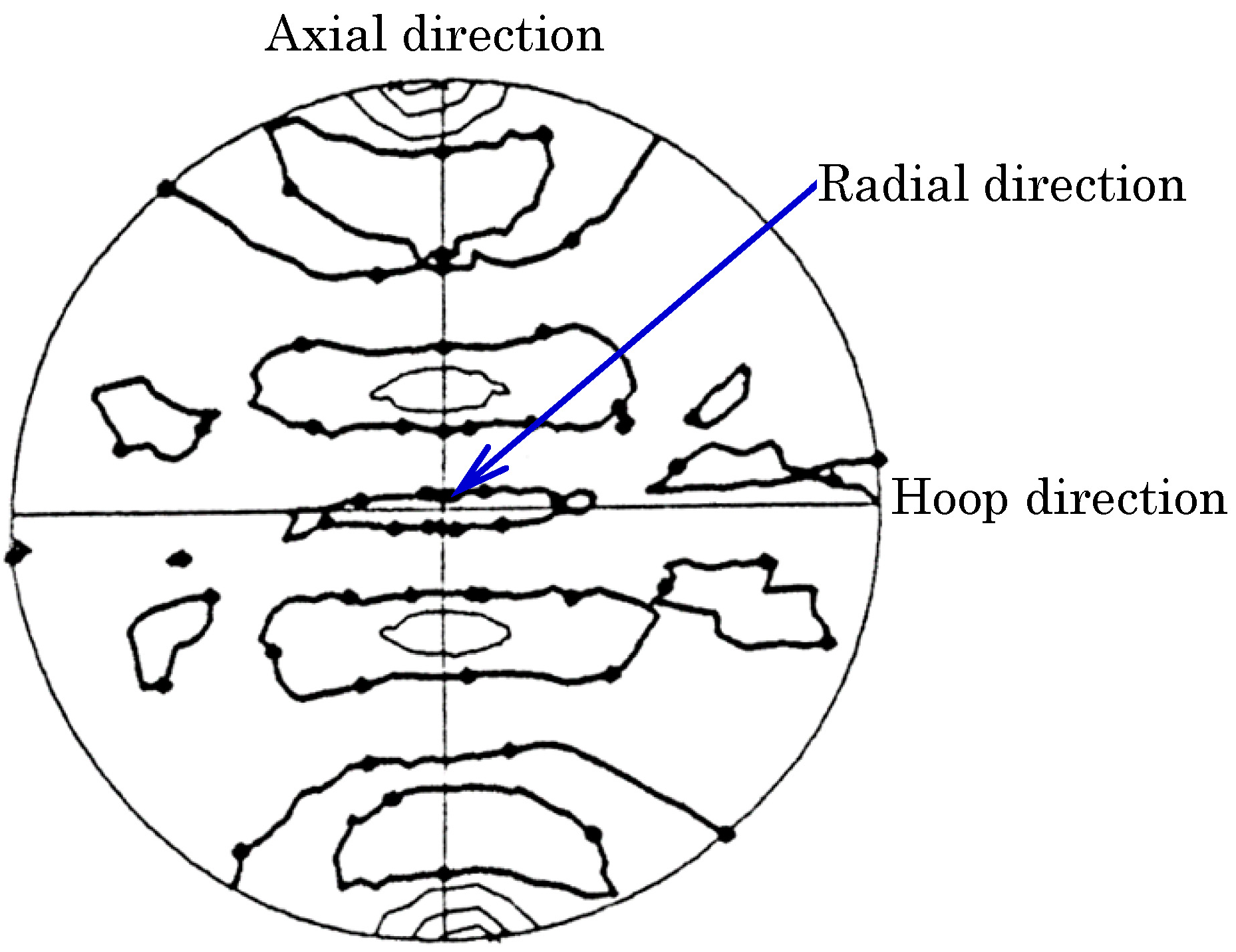
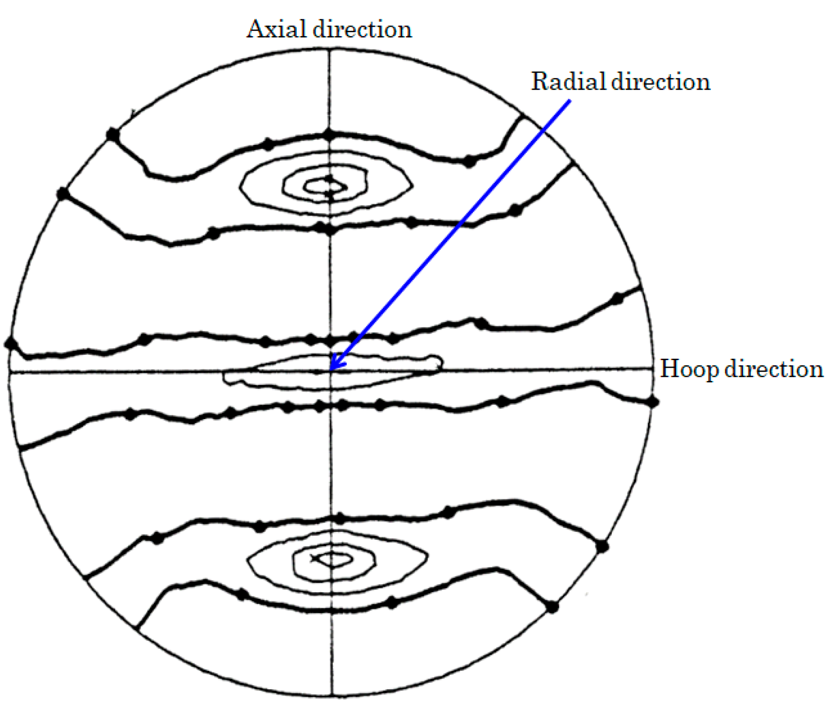
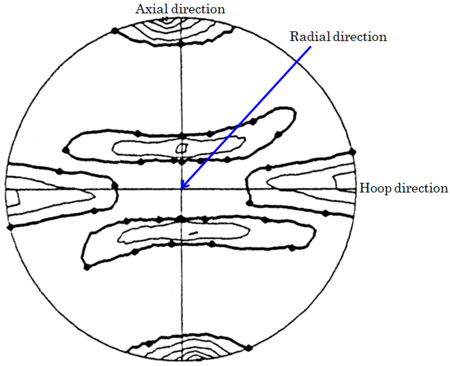
The diffraction peak intensities measured over a full hemisphere of specimen orientations are plotted on stereographic projection pole figures, which follow the conventions of Roe [19]. The principal axes of the original pressure tube are indicated on the pole figures as follows: The axial direction is parallel to the vertical line, the hoop direction is parallel to the horizontal line, and the radial direction is normal to the figure and plotted at the center of the pole figure. For each pole figure, the contour interval is 2.5 multiples of a random distribution (mrd), while the heavy line marked with dots indicates 1 mrd.
The (100), (110), and (002) pole figures of heat-treated Zr–2.5Nb are shown in Figure 8, Figure 9 and Figure 10, respectively. Compared with the non-heat-treated Zr–2.5Nb alloy [14], the texture of heat-treated Zr–2.5Nb was not as strong. Considering the pole figures were approximately mirror symmetric about a plane (3 deviating from the axial-radial plane) vertical to the axial-hoop plane, it is believed that this is due to the misalignment of sample setup. The three directions of principal stresses might deviate several degrees from the corresponding axial, hoop, or radial directions of the measured stresses within the Zr–2.5Nb pressure tube. In theory, the principal stresses and the principal strains should be measured in more than six dimensional measurements directly. According to Hayashi and Root’s previous publication [20], the deviation angle about 10 may lead to a relative error (about 1.5%) of the measured three-dimensional stress components compared with the real principal stress components, i.e., within the same level of the uncertainty of the three-dimensional stress measurements.
Moreover, the pole figures clearly revealed which hkl reflection should be chosen to optimize the measurements of crystal lattice strain in the various principal directions of the pressure tube. For example, the axial and radial 100 reflections, the hoop and radial 110 reflections, and the axial and hoop 002 reflections are relatively easy to obtain high statistical diffraction profiles for strain analysis in a short time.
3.2. Elastic Constants
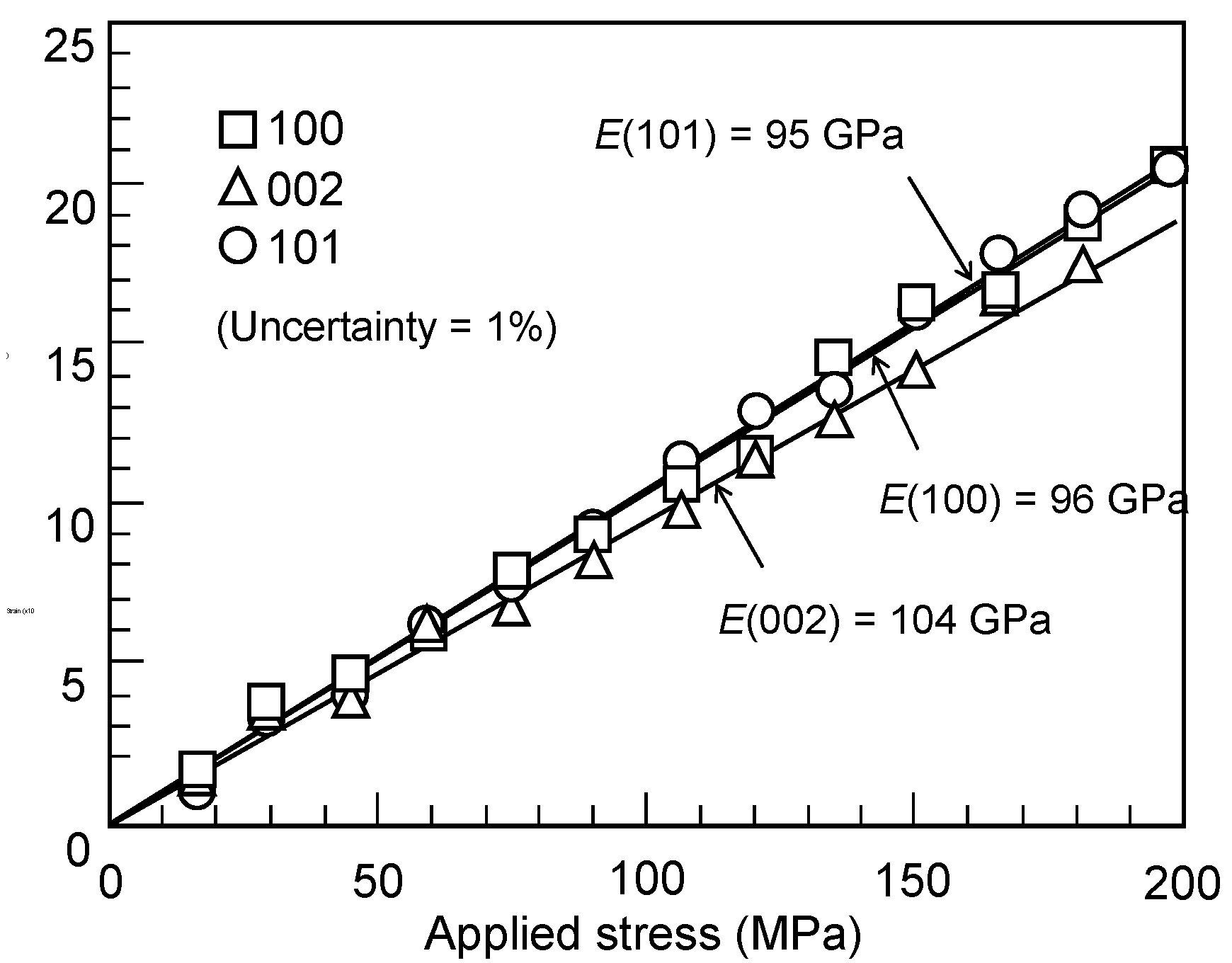
The crystal lattice strain vs the applied stress measured parallel to the direction of tensile loading is presented in Figure 11. The uncertainty of each measurement is comparable to the size of the symbols. Evidently, the tensile lattice strains linearly increase with the applied stress, similar to the bulk strain. The Young’s modulus of the bulk material was obtained as E = 97 GPa. However, the (002) crystal plane dependent strains exhibit a slope distinguishably lower than the general trend. Linear fits yield Young’s moduli of E = 95 GPa for (101) crystal planes, E = 96 GPa for (100) crystal planes and E = 104 GPa for (002) crystal planes.
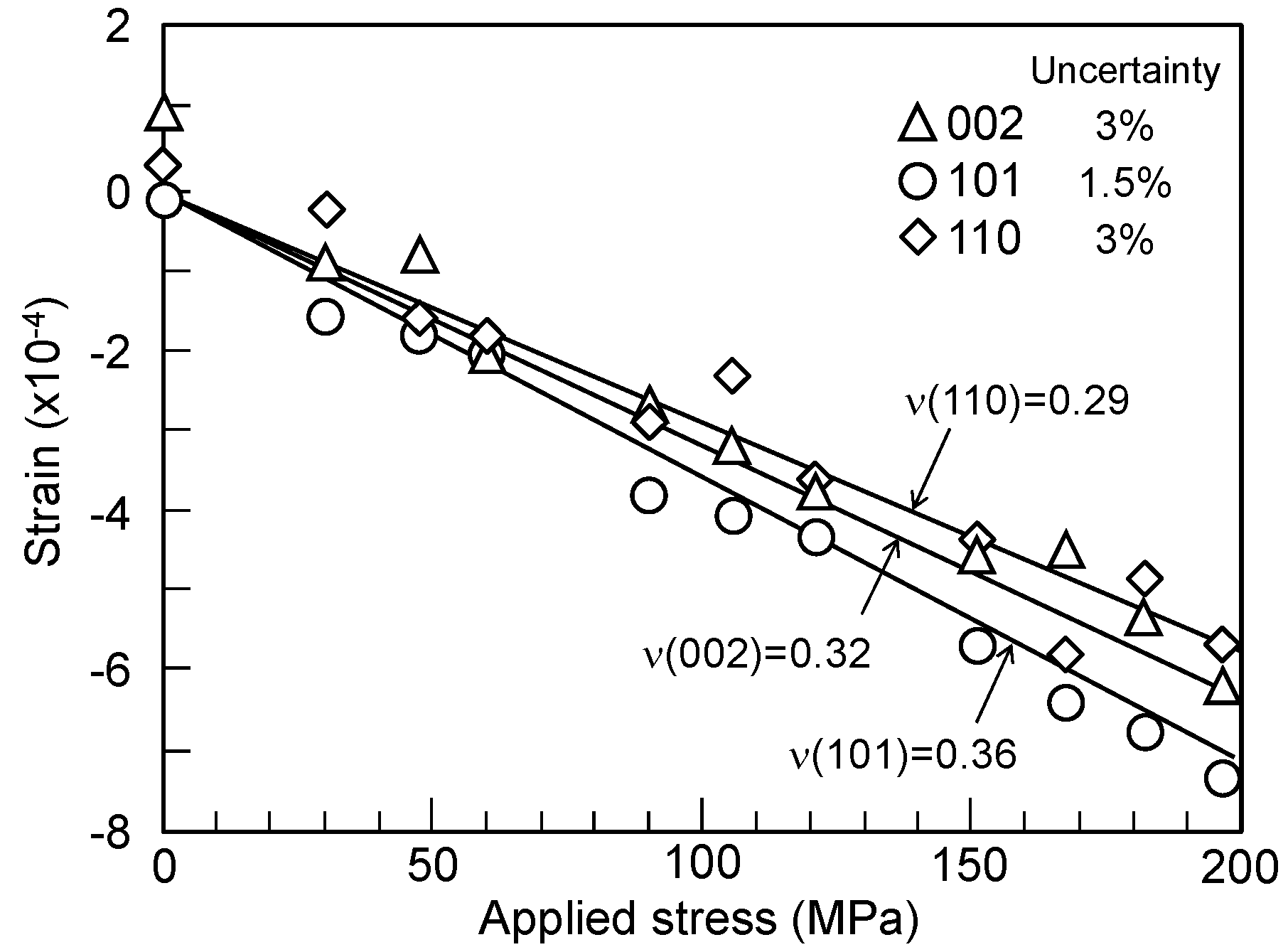
The crystal lattice strains vs the applied stress measured perpendicular to the direction of tensile loading are shown in Figure 12. The measured lattice strains are somewhat scattered. The least of squares calculation results in Poisson’s ratios of ν = 0.36 for (101) crystal planes, ν = 0.29 for (110) crystal planes and ν = 0.32 for (002) crystal plane.
The (hkl) dependence of the elastic constants has been calculated for ferritic steel [9] by a computer program [21] based on the Kröner model of elasticity [7,8]. In ferritic steel, assumptions were made that the material had equiaxed grains with no significant texture and so bulk elastic constants from the literature [6] were employed directly. In the Zr–2.5Nb alloy, neither of these assumptions are valid. However, the Kröner calculation of diffraction elastic constants may be still attempted. Single crystal elastic constants, Cij (unit: GPa), were obtained for pure zirconium from the literature [22]: C11 = 144, C33 = 166, C44 = 33.4, C12 = 74, and C13 = 67. The diffraction elastic constants were calculated with these elastic constants for a hexagonal close-packed crystal structure. The results are presented in Table 2.
Young’s modulus predicted from the random textured pure zirconium with Kröner elastic constants exhibits a small dependence on the crystal plane [16]. In the (002) crystal plane, the predicted E is the stiffest, 6% higher than the bulk average. In the (101) crystal plane, the predicted E is almost the same with the bulk average.
3.3. Residual Stresses
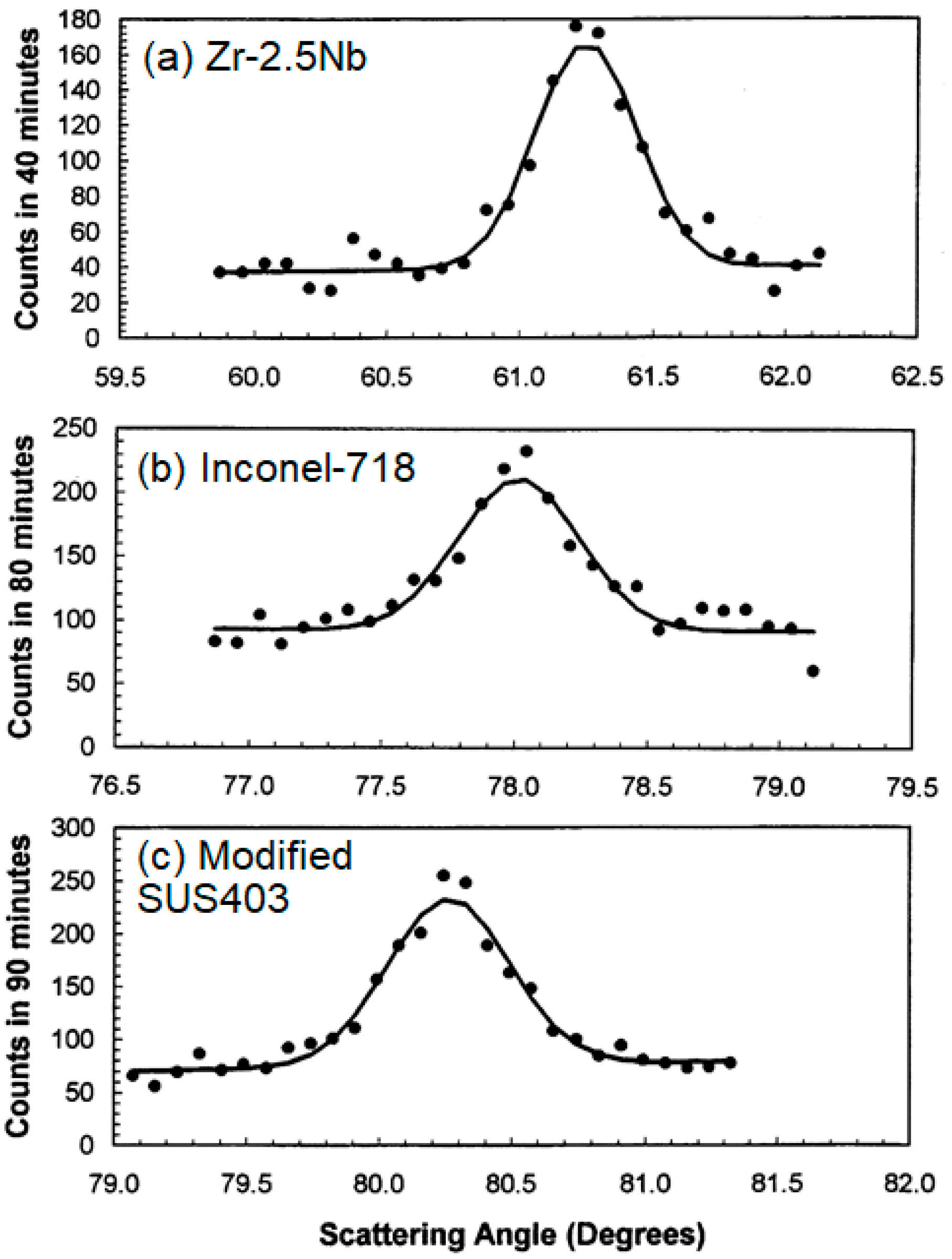
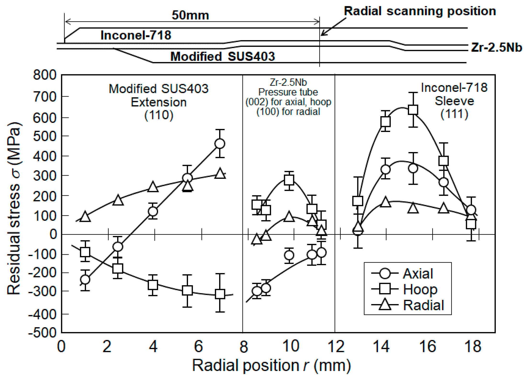
Typical diffraction peak profiles for (a) the 002 reflection of the Zr–2.5Nb alloy, (b) the 111 reflection of the Inconel-718 and (c) the 110 reflection of the modified SUS403 stainless steel obtained from the axial strain measurements are shown as scattered points in Figure 13. The continuous lines indicate the Gaussian fitted curves. The through-thickness variations of the residual stresses calculated from the measured strains with Equation (4) and appropriate diffraction elastic constants are shown in Figure 14.
The overall through-thickness trend of the hoop stresses was from compression in the inner modified SUS403 stainless steel extension through slight tension in the Zr–2.5Nb to a higher tension in the outer Inconel-718 ring. This overall trend was consistent with radial expansion against an outer ring with a very high yield stress. When the rolled-joining expansion tool was removed, the outer ring cannot relax completely to its original dimension because it was constrained by the inner tube under the elastic compressive condition. Superimposed on the overall trend was an additional through-thickness variation in each portion of the tubular joint, especially evident in the Inconel-718, where the hoop stress was less than 200 MPa near the inner and outer surfaces but reached a peak of 650 MPa at the mid-thickness. The origin of this finer-scale stress variation may be linked to the geometry of the crimp and the rolled-joining deformations. The opposing axial residual stresses were observed at the interface between the stainless steel extension and the Zr–2.5Nb pressure tube. The inner extension exhibited a tensile axial stress of 450 MPa near the interface, which was balanced by a compressive axial stress of −300 MPa in the Zr–2.5Nb near the interface.
3.4. Residual Stress Relaxation in a Zr–2.5Nb Pressure Tube
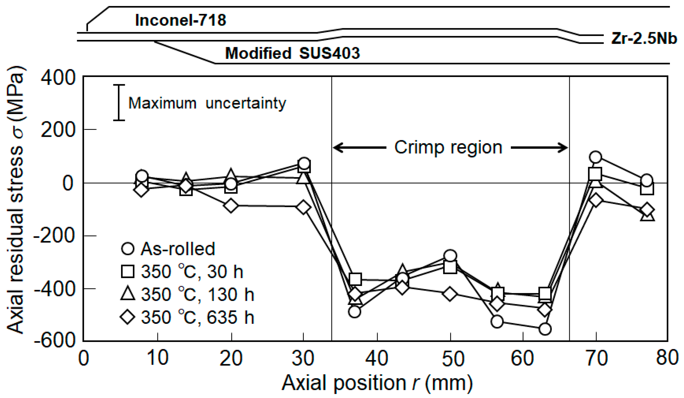
The upper rolled joint was heat treated at 350 °C for 30, 130 and 635 h and the relaxation behavior of the residual stresses was examined. The 350 °C aging for 635 h was equivalent to the 30-year operation in the actual nuclear power plant at the operating temperature of 288 °C. The measured positions were 1 mm from the inside surface of the Zr–2.5Nb pressure tube along the axial direction. Figure 15 shows the axial variation of the axial residual stress due to the 350 °C long-time aging.
Away from the crimp region, the axial residual stresses were lower than 100 MPa at any position under the as-rolled condition. On the other hand, the axial residual stresses at the crimp region were with highly compressive values, quite different from the residual stress distributions away from the crimp region. The mean value of axial residual stress was about −440 MPa. These high compressive residual stresses were caused by an inward motion of the edges of the groove in the Inconel-718 ring when the expansion tool was removed. The same motion exerted a local pull deformation on the Zr–2.5Nb pressure tube immediately adjacent to the crimp region and led to a low axial residual stress.
Fortunately, the residual stresses in the crimp region remained in a strong state of compression, keeping between −300 and −550 MPa during the long-time aging treatment. That is to say, the aging treatment had no evident relaxing effect on the axial residual stresses in the crimp region, suggesting that the rolled joint had a good long-term sealing ability against the leakage of high temperature water.
The radial residual stresses were near to zero within the uncertainty error, except at the edges of the crimp region. Just inside each edge there was a radial compressive stress, −180 ± 50 MPa, while just outside each edge there was a radial tensile stress, 170 ± 60 MPa. The 30 h aging was also sufficient to relieve the small compressive radial stresses both on the outside and inside edge of the crimp region. After 30 h of aging, the radial residual stress at any portion had no evident change.
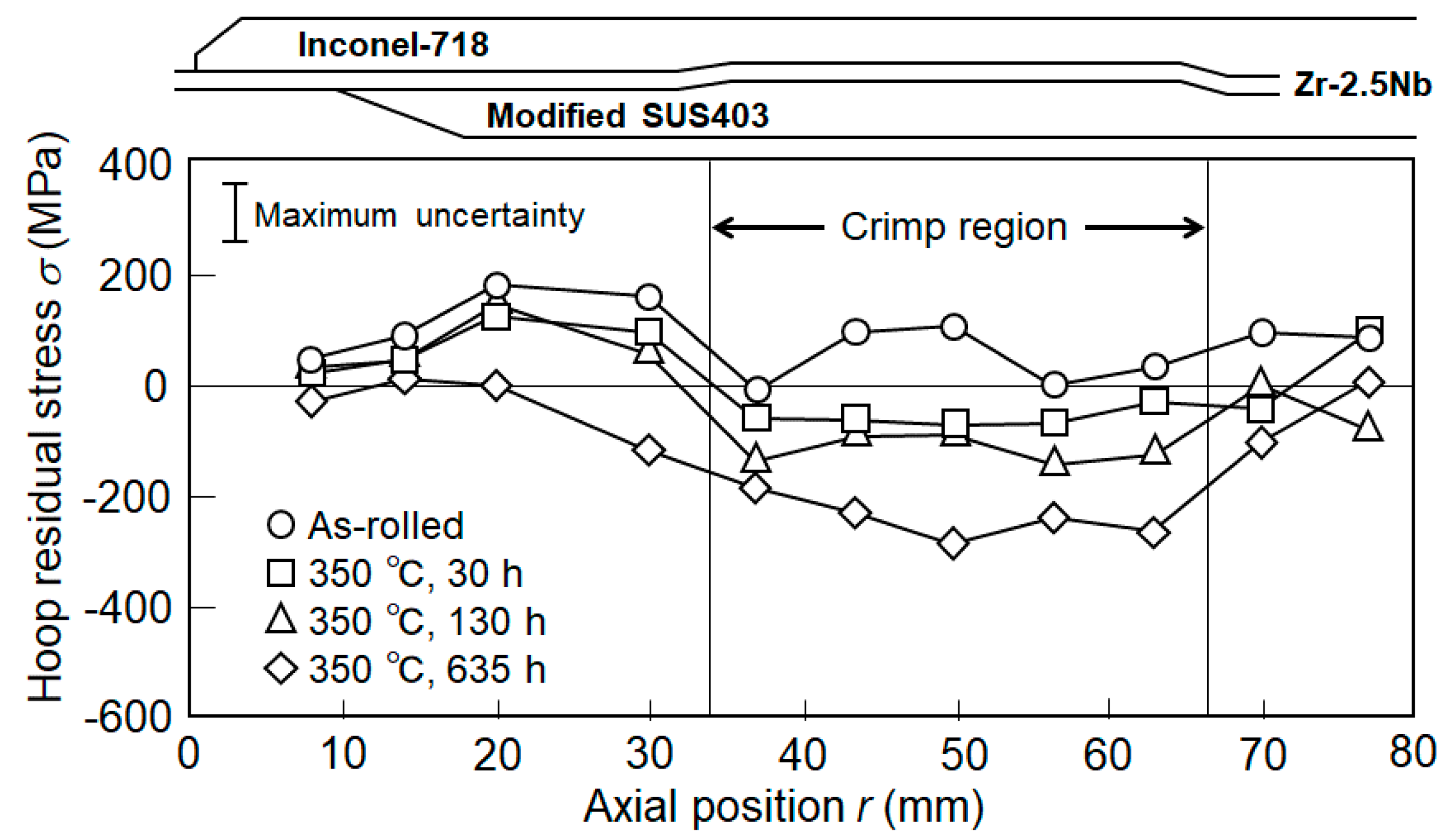
As shown in Figure 16, the tensile hoop stresses appeared outside but near the edges of the crimp region before 350 °C aging. A hoop tension of about 200 MPa appeared adjacent to the inboard or zero-position edge of the crimp region. The average of the residual stresses at the crimp region after rolled-joining was about 80 MPa. However, the hoop stresses exhibited continuous changes as the heat treatments proceeded. Throughout the length of the crimp region, the as-rolled tensile hoop stresses passed through a state of zero stress and into a state of compression on the 350 °C aging treatment for 30, 130 and 635 h, sequentially.
The good way to keep the sealing ability against the leakage of high temperature water in ATR is shrinkage between the modified SUS403 stainless steel extension and the Zr–2.5Nb tube or Incolel718 sleeve and the Zr–2.5Nb tube. As can be seen in Figure 14, while the hoop residual stress in the modified SUS403 stainless steel extension was compressive, the hoop residual stresses in the Zr–2.5Nb tube and Inconel-718 sleeve were tensile. Thus, the sealing ability before the heat treatment can be retained by the shrinkage between the stainless steel and the Zr–2.5Nb tube. After the aging treatment, the residual stresses in the Zr–2.5Nb tube changed to compressive, as shown in Figure 16. While the hoop residual stresses changed from tensile to compressive, the hoop residual stresses in the Inconel-718 sleeve still remained high tensile. Thus, the sealing ability can be retained between the Zr–2.5Nb tube and the Inconel-718 sleeve.
4. Summary and Prospects
Neutron diffraction provides a reliable nondestructive tool for the evaluation of residual stress profiles in an intact upper rolled joint. A little high residual stress was found in the Zr–2.5Nb, especially in the crimp region. Short-time aging treatment at 350 °C relaxed the hoop and axial residual tensile stresses to a certain extent. Repeated heating to a maximum total duration of 635 h led to compressive residual hoop stresses within the crimp region. However, the axial residual compression in the crimp region was not evidently affected by the aging treatment. Away from the crimp region, all three components of residual stress were almost negligible. The Inconel-718 outer sleeve and modified SUS403 stainless steel extension tube also exhibited residual stresses in the as-rolled condition. These components of the rolled joint were not strongly influenced by aging treatment at 350 °C, suggesting that the rolled joint had a good long-term sealing ability against the leakage of high temperature water in ATR.
It should be mentioned that the neutron diffraction experiments in this paper were carried out in the 1990s while the neutron diffraction beam time was limited due to the quite low instrumental accessibility. Considering that only the macro strains and the macro stresses were investigated in this paper by using the limited experimental neutron diffraction data, the effect of texture-related potential intergranular strain on the residual stress [15] was omitted here and the early classic stress model was simply employed. However, such similar pioneering researches involving in the strain, stress and texture evaluation with a little higher uncertainty have an important promotive role to develop and upgrade the neutron diffraction stress and/or texture measurement techniques in Japan using the constant wavelength neutron source at Japan Research Reactor No.3 (JRR-3, Tokai, Japan) [23,24,25,26,27] and the spallation neutron source at Japan Proton Accelerator Research Complex (J-PARC, Tokai, Japan) [28,29,30]. Actually, the rapid texture measurement technique [29] and the simultaneous measurement technique of the phase fractions, the strain, the stress and the texture [30] have been well established using the BL20 (iMATERIA) and BL19 (TAKUMI) neutron diffractometers at J-PARC, respectively, which provide us wider accessibility to neutron diffraction techniques for accelerating the research and development activities of advanced engineering materials and related products [30], together with other domestic and oversea neutron diffraction facilities, for example, the diffractometer for residual stress analysis (RESA-1) at JRR-3, Japan [31,32] and the Residual Stress Neutron Diffractometer (RSND) at the China Mianyang Research Reactor (CMRR), Beijing, China) [33].
Author Contributions
Conceptualization, M.H.; Methodology, M.H., R.B.R.; Validation, M.H., R.B.R.; Formal Analysis, M.H., R.B.R.; Investigation, M.H., J.H.R., R.B.R., P.X.; Data Curation, M.H., R.B.R.; Writing-Original Draft Preparation, M.H., R.B.R., P.X.; Writing-Review & Editing, M.H., P.X.; Supervision, M.H., J.H.R.; Project Administration, M.H.
Conflicts of Interest
The authors declare no conflict of interest.
References
- Mita, S.; Akebi, M.; Sawamura, O.; Kondo, T. Development of the Advanced Thermal Reactor in Japan. Nuclear Eng. Des. 1993, 144, 283–292. [Google Scholar] [CrossRef]
- Uematsu, S.; Mitsugi, T.; Kikuchi, K.; Kobayashi, T.; Yokoya, J. Irradiation Experiment of MOX Fuel Assembly for Advanced Thermal Reactor. J. Nucl. Sci. Technol. 1997, 39, 870–880. [Google Scholar]
- Allen, A.J.; Hutching, M.T.; Windsor, C.G.; Andreani, C. Neutron diffraction methods for the study of residual stress fields. Adv. Phys. 1985, 34, 445–473. [Google Scholar] [CrossRef]
- Bourke, M.A.M.; MacGillivray, H.J.; Webster, G.A.; Low, K.S.; Webster, P.J. Improving the resolution of neutron diffraction residual stress measurements in engineering components. In Proceedings of the IITT International Conference on Fatigue and Stress, Paris, France, 10 July 1987. [Google Scholar]
- Bourke, M.A.M.; Smith, D.J.; Webster, G.A.; Webster, P.J. Neutron diffraction measurements of residual stresses in plastically deformed cracked beams. In Proceedings of the 9th Conference on Experimental Mechanics, Copenhagen, Denmark, 20–24 August 1990; pp. 1198–1206. [Google Scholar]
- Webster, G.A. Role of neutron diffraction in engineering stress analysis. In Measurement of Residual and Applied Stress Using Neutron Diffraction; Hutching, M.T., Krawits, A.D., Eds.; Springer: Dordrecht, The Netherlands, 1992; pp. 21–35. [Google Scholar]
- Buttle, D.J.; Hutching, M.T. Residual stress measurement at NNDTC. Br. J. Nondestruc. Test. 1992, 34, 175–182. [Google Scholar]
- Hayashi, M.; Ishiwata, M.; Minakawa, N.; Funahashi, S.; Root, J.H. Diffraction Plane Dependence of Elastic Constants in Ferritic Steel in Neutron Diffraction Stress Measurement. ZAIRYO-J. Soc. Mater. Sci. Jpn. 1995, 44, 1115–1120. (In Japanese) [Google Scholar] [CrossRef]
- Kröner, E. Berechnung der elastischen Konstanten des Vielkristalls aus den Konstanten des Einkristalls. Z. Physik. 1958, 151, 504–518. [Google Scholar] [CrossRef]
- Hayashi, M.; Ishiwata, M.; Minakawa, N.; Funahashi, S. Residual Stress Measurement in Socket Welded Joints by Neutron Diffraction. ZAIRYO-J. Soc. Mater. Sci. Jpn. 1995, 44, 1464–1469. (In Japanese) [Google Scholar] [CrossRef]
- Hayashi, M.; Ishiwata, M.; Morii, S.; Minakawa, N. Residual Stress Distribution in Carbon Steel Pipe Welded Joints Measured by Neutron Diffraction. ZAIRYO-J. Soc. Mater. Sci. Jpn. 1996, 45, 772–778. (In Japanese) [Google Scholar] [CrossRef]
- Mochizuki, M.; Hayashi, M.; Hattori, T. Numerical Analysis of Welding Residual Stress and Its Verification Using Neutron Diffraction Measurement. Trans. ASME 2000, 122, 98–103. [Google Scholar] [CrossRef]
- Holden, T.M.; Hosbons, R.R.; Root, J.H.; Ibrahim, E.F. Neutron Diffraction Measurements of Strain and Texture in Welded Zr–2.5Nb Tube. MRS Proc. 1988, 142, 59–64. [Google Scholar] [CrossRef]
- Root, J.H.; Colemen, C.E.; Bowden, J.W.; Hayashi, M. Residual Stresses in Steel and Zirconium Weldments. J. Press. Vess. Technol. 1997, 119, 137–141. [Google Scholar] [CrossRef]
- MacEwen, S.R.; Christodoulou, N.; Salinas-Rodríguez, A. Residual grain-interaction stresses in zirconium alloys. Meter. Trans. A 1990, 21, 1083–1095. [Google Scholar] [CrossRef]
- Hayashi, M.; Kimoto, H.; Michishita, H.; Root, J.H. Measurement of Texture and Elastic Constants of Zr–2.5%Nb Alloy by Neutron Diffratcion. ZAIRYO-J. Soc. Mater. Sci. Jpn. 1997, 46, 743–749. (In Japanese) [Google Scholar] [CrossRef]
- Hayashi, M.; Ohkido, S.; Morii, Y.; Minakawa, N. Measurement of Residual Stress in Structural Components by Neutron Diffraction; Technical Report; The Society of Material Science: Kyoto, Japan, 2001; pp. 418–423. [Google Scholar]
- Hayashi, M.; Ohkico, S.; Morii, Y.; Minakawa, N.; Root, J.H. Measurement of Residual Stress in Structural Components by Neutron Diffraction and Proposal of Measurement Standard. Mater. Sci. Forum 2003, 426–432, 3969–3974. [Google Scholar] [CrossRef]
- Roe, R.J. Description of Crystallite Orientation in Polycrystalline Materials. 3. General Solution to Pole Figure Inversion. J. Appl. Phys. 1965, 36, 2024–2031. [Google Scholar] [CrossRef]
- Hayashi, M.; Root, J.H. Effect of miss-alignment on residual stress in carbon steel socket welded joint. Zairyo-J. Soc. Mater. Sci. Jpn. 2014, 63, 602–607. [Google Scholar] [CrossRef]
- Benken, H.; Hauk, V. Berechnung der röntgenographischen Elastizitätkonstanten (REK) des Vielkristalls aus Einkristalldaten für beliebige Kristalsymmetrie. Z. Metallkde. 1986, 77, 620–626. [Google Scholar]
- Smithells, C.J.; Brandes, E.A.; Fulmer Research Institute. Smithells Metals Reference Book, 6th ed.; Brandes, E.A., Ed.; Fulmer Research Institute Ltd., Butterworth Scientific: London, UK, 1983. [Google Scholar]
- Suzuki, H.; Holden, T.M. Neutron diffraction measurements of stress in an austenitic butt weld. J. Strain Anal. Eng. Des. 2006, 41, 575–582. [Google Scholar] [CrossRef]
- Xu, P.G.; Tomota, Y.; Suzuki, H.; Suzuki, T.; Machiya, S.; Yin, F.X. Bulk Texture Measurement of Interstitial-Free Annealed Steel Using Gaussian Integrated Intensities of Neutron Diffraction Spectra. Mater. Trans. 2008, 49, 2033–2039. [Google Scholar] [CrossRef] [Green Version]
- Suzuki, H.; Kanematsu, M.; Kusunoki, K. Neutron diffraction studies on strain evaluation of rebar in reinforced concrete. Powder Diffr. 2009, 24, S68–S72. [Google Scholar] [CrossRef]
- Tsuchiya, Y.; Suzuki, H.; Umeno, T.; Machiya, S.; Osamura, K. Development of a cryogenic load frame for a neutron diffractometer. Meas. Sci. Technol. 2010, 21, 025904. [Google Scholar] [CrossRef]
- Xu, P.G.; Akita, K.; Suzuki, H.; Metoki, N.; Moriai, A. Establishment and Optimization of Angle Dispersive Neutron Diffraction Bulk Texture Measurement Environments. Mater. Trans. 2012, 53, 1831–1836. [Google Scholar] [CrossRef] [Green Version]
- Suzuki, H.; Harjo, S.; Abe, J.; Xu, P.G.; Aizawa, K.; Akita, K. Effects of gauge volume on pseudo-strain induced in strain measurement using time-of-flight neutron diffraction. Nucl. Instrum. Methods Phys. Res. Sect. A 2013, 715, 28–38. [Google Scholar] [CrossRef]
- Onuki, Y.; Hoshikawa, A.; Sato, S.; Xu, P.G.; Ishigaki, T.; Saito, Y.; Todoroki, H.; Hayashi, M. Rapid measurement scheme for texture in cubic metallic materials using time-of-flight neutron diffraction at iMATERIA. J. Appl. Cryst. 2016, 49, 1579–1584. [Google Scholar] [CrossRef]
- Xu, P.G.; Harjo, S.; Ojima, M.; Suzuki, H.; Ito, T.; Gong, W.; Vogel, S.C.; Inoue, J.; Tomata, Y.; Aizawa, K.; et al. High stereographic resolution texture and residual stress evaluation using time-of-flight neutron diffraction. J. Appl. Cryst. 2018, 51, 746–760. [Google Scholar] [CrossRef] [PubMed]
- Ojima, M.; Inoue, J.; Nambu, S.; Xu, P.G.; Akita, K.; Suzuki, H.; Koseki, T. Stress Partitioning Behavior of Multilayered Steels during Tensile Deformation Measured by in situ Neutron Diffraction. Scr. Mater. 2012, 66, 139–142. [Google Scholar] [CrossRef]
- Suzuki, T.; Yamanaka, K.; Ishino, M.; Nagai, K.; Tsuru, E.; Shinohara, Y.; Xu, P.G. Neutron Diffraction Study on Anisotropy of Strain Age Hardening in Ferritic steel. Tetsu-to-Hagane 2012, 98, 262–266. (In Japanese) [Google Scholar] [CrossRef]
- Mo, F.; Sun, G.; Li, J.; Zhang, C.; Wang, H.; Chen, Y.; Liu, Z.; Yang, Z.; Li, H.; Yang, Z.; et al. Recent Progress of Residual Stress Distribution and Structural Evolution in Materials and Components by Neutron Diffraction Measurement at RSND. Quantum Beam Sci. 2018, 2, 15. [Google Scholar] [CrossRef]
Figure 1.
Upper cross-sectional structure of a pressure tube rolled joint.

Figure 2.
Construction of Zr–2.5Nb sample for texture measurements [16].
Figure 2.
Construction of Zr–2.5Nb sample for texture measurements [16].

Figure 3.
Setup of a sample and a Eulerian cradle for neutron diffraction texture measurements [16].
Figure 3.
Setup of a sample and a Eulerian cradle for neutron diffraction texture measurements [16].

Figure 4.
In situ tensile deformation loading frame mounted in the horizontal orientation on the neutron diffractometer for measuring the diffraction elastic constants [8].
Figure 4.
In situ tensile deformation loading frame mounted in the horizontal orientation on the neutron diffractometer for measuring the diffraction elastic constants [8].

Figure 5.
Illustration for the orientation setup of a rolled joint in the incident-diffraction plane for three-dimensional strain measurements.
Figure 5.
Illustration for the orientation setup of a rolled joint in the incident-diffraction plane for three-dimensional strain measurements.

Figure 6.
Setup of a rolled joint of a pressure tube for radial direction residual strain measurements.
Figure 6.
Setup of a rolled joint of a pressure tube for radial direction residual strain measurements.

Figure 7.
Longitudinal radial section showing dimensions and measurement position.

Figure 8.
(100) pole figure for a heat-treated Zr–2.5Nb pressure tube, stereographic projection, contour interval is 2.5 multiples of a random distribution (mrd).
Figure 8.
(100) pole figure for a heat-treated Zr–2.5Nb pressure tube, stereographic projection, contour interval is 2.5 multiples of a random distribution (mrd).

Figure 9.
(110) pole figure for a heat-treated Zr–2.5Nb pressure tube, stereographic projection, contour interval is 2.5 mrd.
Figure 9.
(110) pole figure for a heat-treated Zr–2.5Nb pressure tube, stereographic projection, contour interval is 2.5 mrd.

Figure 10.
(002) pole figure for a heat-treated Zr–2.5Nb pressure tube, stereographic projection, contour interval is 2.5 mrd.
Figure 10.
(002) pole figure for a heat-treated Zr–2.5Nb pressure tube, stereographic projection, contour interval is 2.5 mrd.

Figure 11.
Plots of axial strain versus applied stress.

Figure 12.
Plots of transverse strain versus applied stress.

Figure 13.
Typical diffraction peaks for (a) the 002 reflection of the Zr–2.5Nb alloy, (b) the 111 reflection of the Inconel-718 and (c) the 110 reflection of the modified SUS403 stainless steel. The uncertainty in each data point is the square root of the value.
Figure 13.
Typical diffraction peaks for (a) the 002 reflection of the Zr–2.5Nb alloy, (b) the 111 reflection of the Inconel-718 and (c) the 110 reflection of the modified SUS403 stainless steel. The uncertainty in each data point is the square root of the value.

Figure 14.
Through-thickness variation of three-dimensional residual stresses in the as-rolled rolled joint.
Figure 14.
Through-thickness variation of three-dimensional residual stresses in the as-rolled rolled joint.

Figure 15.
Axial variation of the axial residual stress in a Zr–2.5Nb pressure tube due to the 350 °C aging.
Figure 15.
Axial variation of the axial residual stress in a Zr–2.5Nb pressure tube due to the 350 °C aging.

Figure 16.
Axial variation of the hoop residual stress in a Zr–2.5Nb pressure tube due to the 350 °C aging.
Figure 16.
Axial variation of the hoop residual stress in a Zr–2.5Nb pressure tube due to the 350 °C aging.


Table 1.
Diffraction elastic constants of the Inconel-718 alloy and the modified SUS403 stainless steel.
Table 1.
Diffraction elastic constants of the Inconel-718 alloy and the modified SUS403 stainless steel.
| Material | hkl | E (GPa) | v |
|---|---|---|---|
| Inconel-718 | 111 | 259 | 0.27 |
| Modified SUS403 | 110 | 224 | 0.28 |
Table 2.
Comparison of bulk and (hkl)-dependent diffraction elastic constants (unit: GPa) [16].
Table 2.
Comparison of bulk and (hkl)-dependent diffraction elastic constants (unit: GPa) [16].
| Kröner Elastic Constants | ||||
| Bulk Average | (100) | (002) | (101) | |
| Young’s Module | 97 | 98 | 110 | 95 |
| Poisson’s ratio | 0.33 | 0.33 | 0.32 | 0.34 |
| Measured elastic constants | ||||
| Extensometer | (100) | (002) | (101) | |
| Young’s Module | 97 | 96 | 104 | 95 |
| Poisson’s ratio | 0.34 | 0.34 | 0.32 | 0.36 |
© 2018 by the authors. Licensee MDPI, Basel, Switzerland. This article is an open access article distributed under the terms and conditions of the Creative Commons Attribution (CC BY) license (http://creativecommons.org/licenses/by/4.0/).
Share and Cite
MDPI and ACS Style
Hayashi, M.; Root, J.H.; Rogge, R.B.; Xu, P. Evaluation of Residual Stress Relaxation in a Rolled Joint by Neutron Diffraction. Quantum Beam Sci. 2018, 2, 21. https://0-doi-org.brum.beds.ac.uk/10.3390/qubs2040021
AMA Style
Hayashi M, Root JH, Rogge RB, Xu P. Evaluation of Residual Stress Relaxation in a Rolled Joint by Neutron Diffraction. Quantum Beam Science. 2018; 2(4):21. https://0-doi-org.brum.beds.ac.uk/10.3390/qubs2040021
Chicago/Turabian StyleHayashi, Makoto, John H. Root, Ronald B. Rogge, and Pingguang Xu. 2018. "Evaluation of Residual Stress Relaxation in a Rolled Joint by Neutron Diffraction" Quantum Beam Science 2, no. 4: 21. https://0-doi-org.brum.beds.ac.uk/10.3390/qubs2040021