1. Introduction
Proton-exchange membrane fuel cells (PEMFCs) are the most common type of fuel cell for transport applications. Several subsystems are necessary to sustain the fuel cell’s electrochemical reaction of hydrogen and oxygen to water. Among those subsystems, the cathode system is the most expensive and has the highest power demand [
1]. Blunier and Miraoui state that the main task of the cathode system is to provide air at the right temperature, pressure, humidity and mass flow [
2]. Furthermore, the cathode system is responsible for removing the product water from the stack. The stack cell voltage increases with a higher working pressure. This advantage is countered by the power necessary for the compression. According to Pischinger et al., the optimal working pressure is about 2.0 bar [
3]. Several studies comparing different kinds of compressors have found turbochargers with a turbine to be best suited for PEMFCs [
1,
4,
5]. Lück et al. have analysed the system behaviour of such a turbocharger with a pseudo bond graph approach [
6]. Schödel et al. [
7] and Menze et al. [
8] have discussed performance map extensions for the compressor and turbine of the same fuel cell turbocharger as studied in this paper.
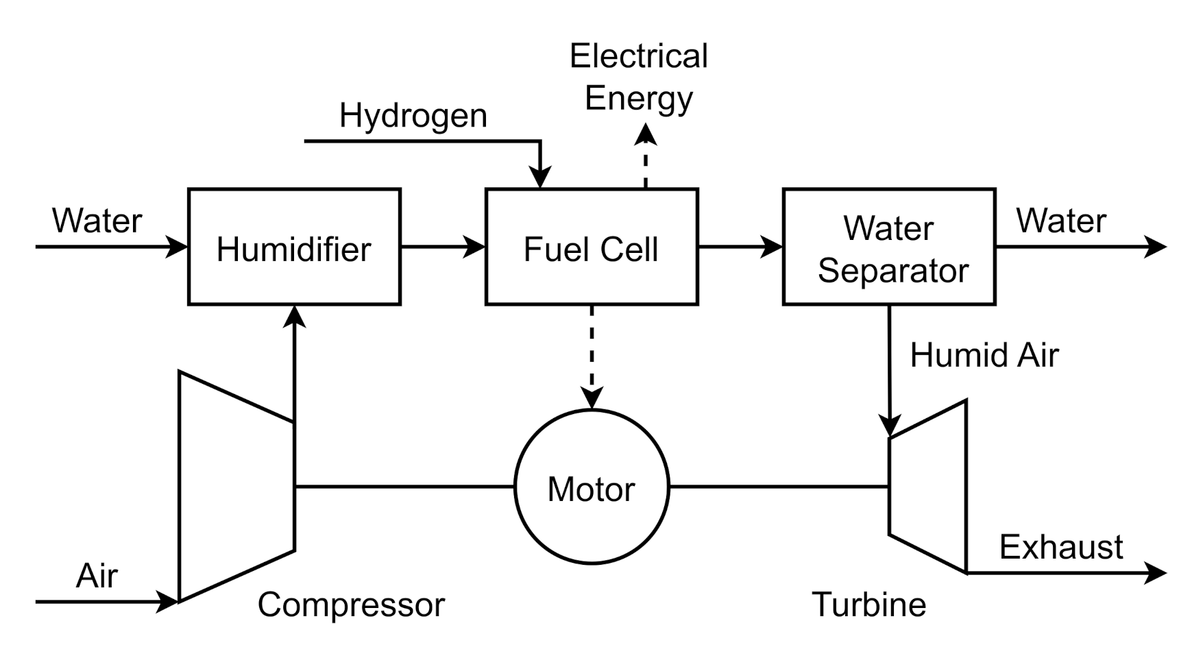
Figure 1 presents a schematic of the system in which the cathode gas flow passes through the compressor, a humidifier, the fuel cell, a water separator and the turbine. The liquid water in the exhaust gas of the fuel cell is separated before entering the turbine. However, the air has a high humidity level at the turbine inlet. The expansion of the flow in the turbine saturates the humid air and water droplets are formed. This condensation has a strong influence on the efficiency and power output of the turbine. The present study focuses on the detailed numerical modelling of this condensation process in the radial turbine of an automotive fuel cell turbocharger. So far, the authors are not aware of any study that deals with the condensation process in a fuel cell turbocharger. However, condensation phenomena in turbomachinery are well known from steam turbines of power plants [
9]. The latest wet-steam Special Issues offer a comprehensive review of the current state of research in this field [
10,
11,
12,
13]. The present study uses a Euler–Lagrange approach which has been applied to steam turbines previously, for example, by Young [
14], Gerber [
15] and Sasao et al. [
16]. Schuster et al. applied the approach to condensation phenomena and droplet deposition in radial turbines [
17]. A review of Eulerian–Lagrangian methods for multiphase flows was undertaken by Subramaniam [
18].
In the first section of this study, the basics of nucleation and condensation are presented. Subsequently, details on implementation and validation are given. Next, the turbine to be investigated is presented and its performance is discussed. Finally, the condensing flow is analysed in detail.
2. Theory of Nucleation and Condensation
The general behaviour of expanding vapour is well known and described, for example, by Starzmann et al. [
19]. The saturation temperature of water vapour decreases during expansion and the corresponding cooling of the flow. Pure gas flow provides no nuclei for a heterogeneous nucleation and thus the vapour subcools. With increasing subcooling, the critical radius for stable homogenous nuclei decreases. At a subcooling of about 30 K, the probability of stable nuclei formation and thus the nucleation rate increases sharply. This provides a large surface area for the onset of condensation and the release of latent heat. Droplets form, the temperature rises and the vapour flow approaches equilibrium. The assumption of negligible heterogeneous condensation is valid because the particle density in the fuel cell outflow is too small by several orders of magnitude to significantly affect the flow. The reason for this low particle density is the efficient filtering of the fuel cell inflow and the separation of liquid water originating from the fuel cell itself before the turbine. In addition, the water vapour entering the turbine is free of chemical impurities that could influence nucleation. The classical nucleation theory and its application to wet steam was reviewed by Bakhtar et al. [
20]. The classical homogenous nucleation rate
per unit volume of mixture is given by
where
is the supersaturation ratio and
is the radius of a critical droplet in an unstable equilibrium with the surrounding vapour. The classical isothermal nucleation theory assumes that vapour and droplet temperature are equal. This assumption is overcome by the non-isothermal correction (NISO) of Kantrowitz [
21].
It typically reduces the nucleation rate for water by a factor of 50–100 and takes the form
Reviews on condensation have been carried out by Young [
22] and more recently by Lamanna [
23]. In principle, the droplet growth process consists of the net flux of vapour molecules towards the droplet and the concurrent latent heat flux away from the droplet. This study uses the growth law by Young [
22] which is an advancement of the growth law by Gyarmathy [
24]. Young’s growth law takes the form
with the quantity
The modelling parameter refers to the relation of condensation and evaporation. A positive value for the modelling parameter adds the option to allow a free molecular regime surrounding the droplet. However, is often set to zero.
3. Numerical Implementation and Validation
The above explained theory of nucleation and condensation was implemented into the discrete phase model (DPM) of Ansys Fluent 19.2, as described by Wittmann et al. [
25]. The principle is as follows. First, each mesh cell was checked for a minimal nucleation rate. Whenever the minimal nucleation rate was exceeded, droplets were initialized. A higher minimal nucleation rate results in fewer DPM particles and thus accelerates the calculation; however, accuracy may be reduced. While a minimal nucleation rate of
10
15 (m
−3s
−1) was often used in previous studies, e.g., by Schuster et al. [
26] or Gerber [
15], the authors found that solution convergence requires a significantly smaller minimal nucleation rate of
10
12 (m
−3s
−1) for the nozzle validation cases and
10
14 (m
−3s
−1) for the turbine cases. All droplets that were initialized in the same mesh cell were grouped together in parcels which form the DPM particles. The droplets were initialized with the critical radius and a velocity equal to the vapour phase. The droplet parcels were transported through the fluid domain and the aforementioned growth law of Young [
22] was applied to model the condensation. The quasi-steady droplet temperature during condensation was calculated with the approximation of Gyarmathy [
24]:
According mass sinks and energy sources were added to the vapour phase. Droplet evaporation was not considered. Apart from the spherical drag law of Morsi and Alexander [
27], no other forces such as the thermophoretic force were applied to the droplets. All simulations use the SST-k-
turbulence model with viscous heating and were performed under steady-state conditions. Due to the strong thermodynamic coupling of the two phases, numerical stability requires a rather strong under relaxation of the discrete phase sources and also pseudo transient under relaxation. All water properties necessary for the calculation of nucleation and condensation are calculated with the equations of the International Association for the Properties of Water and Steam (IAPWS) [
28]. The Euler phase itself is modelled with ideal gas equations. Humid air is assumed to be an ideal gas mixture of nitrogen, oxygen and water vapour.
Homogeneous nucleation and condensation of droplets is a spontaneous physical process. Thus, small changes in the physical quantities lead to large differences. Therefore, an accurate numerical model requires a thorough validation. Supersonic nozzle flows of pure vapour are common validation cases for nucleation and condensation. Recently, the participants of the International Wet Steam Modeling Project (IWSMP) analysed well-known nozzle test cases, mostly with Euler–Euler approaches [
19]. The authors of the present study have discussed their Euler–Lagrange validation results for four test cases of the IWSMP earlier [
29]. This study uses the same parameter set with the classical nucleation theory, NISO correction, Young’s growth law with
= 13,
= 0 and the surface tension of a planar water surface scaled by a factor of 1.05.
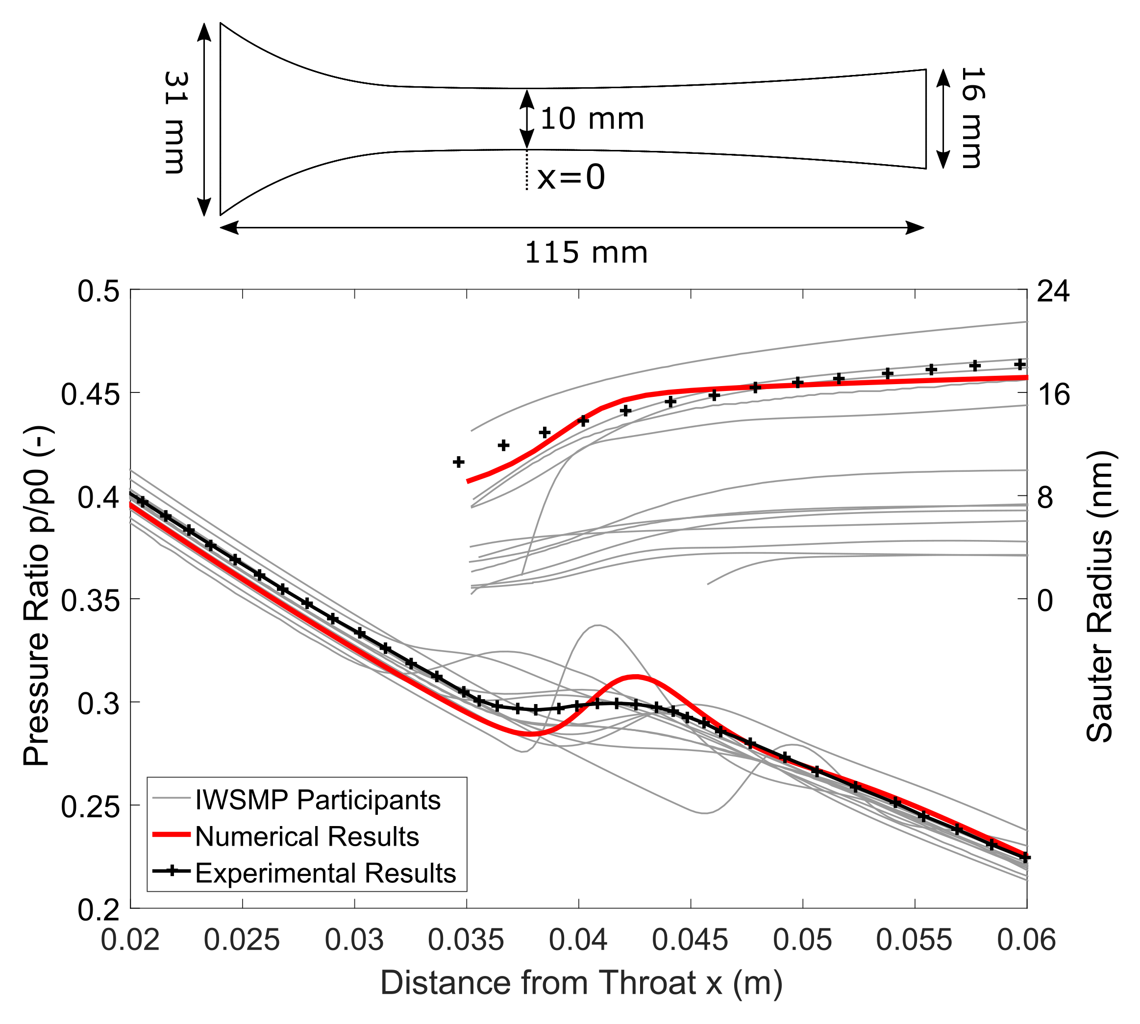
One test case of the IWSMP, the nozzle of Moses and Stein [
30], case 252, shall be presented here again. The nozzle has a throat height of 10 mm and inlet stagnation conditions of
= 40,050 Pa and
= 374.3 K. Boundary conditions, experimental data and the mesh used were provided by the IWSMP. This ensures an optimal comparability. Available experimental data are measurements of pressure and the Sauter mean droplet radius along the nozzle centreline.
Figure 2 shows the geometry of the nozzle as well as the experimental data in black, the numerical results of this study in red and the results of the participants of the IWSMP in grey. The numerical data show a very good agreement with the experimental results both for the pressure and for the mean Sauter droplet radius. The slight deviation upstream of the condensation zone between numerical and experimental pressure data is due to the assumption of a quasi-2D flow and is not present in a 3D simulation.
Thus, the chosen Euler–Lagrange approach is well able to simulate the non-equilibrium process of nucleation and condensation. The resolution of full droplet spectra and the calculation of individual droplet trajectories are the main advantages of this approach. Besides the typical restrictions of RANS simulations, the main drawbacks of the approach are the necessity to use frozen rotor interfaces and the high computational effort required for large numbers of droplet parcels.
4. Application to the Turbine of a Fuel Cell Turbocharger
After the successful validation, the described model was applied to the radial turbine of an automotive fuel cell turbocharger. The turbine has 10 stator vanes and 13 rotor blades.
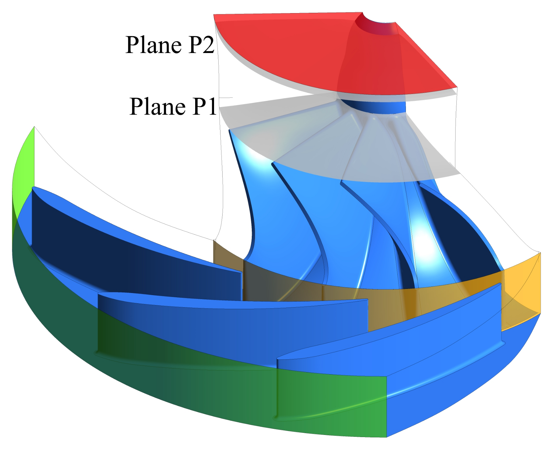
Figure 3 shows the computational domain. The plane P1 just behind the rotor and P2 just before the outlet are the main analysis planes for this study. Discrete droplet paths cannot be transferred over a mixing plane, hence a frozen rotor interface (shown in orange) was chosen. Hellstrom and Fuchs have shown that in the case of a vaned stator, the volute has only a limited influence on the rotor flow [
31]. As will be shown later, nucleation and condensation only take place in the rotor. Therefore, the influence of the volute was assumed to be insignificant for the purposes of this study. In addition, omitting the volute significantly reduces the required computational power. The stator channel was slightly widened for an exact stage matching of three stator vanes and four rotor blades. The inflow at the mass flow inlet (green) was assumed with zero incidence to the stator vanes. All analyses were conducted at the design mass flow and with 344.88 K total temperature at the inlet. The mass fraction of oxygen at the inlet was reduced to 11.3% due to the fuel cell reaction. The outlet (red) is defined by an average static pressure of 1013 hPa. The gap between the stator and rotor hub was modelled as a free slip wall. All other boundaries are either no slip walls or rotational periodicities. The heat transfer away from the turbine is rather limited, hence the assumption of adiabatic walls. The structured mesh consists of 756 k nodes for each rotor blade and 492 k nodes for each stator vane. A grid refinement study found a grid convergence index (GCI) of less than 3% for the mesh. The average
is less than 1.
The performance of the turbine depends on the relative humidity of the inflow. For the following analyses, the mass fraction of water vapour at the stator inlet was varied. All further mentions of relative humidity refer to the stagnation state of the turbine inflow. Values greater than 100% indicate that the flow is already subcooled at the turbine inlet.
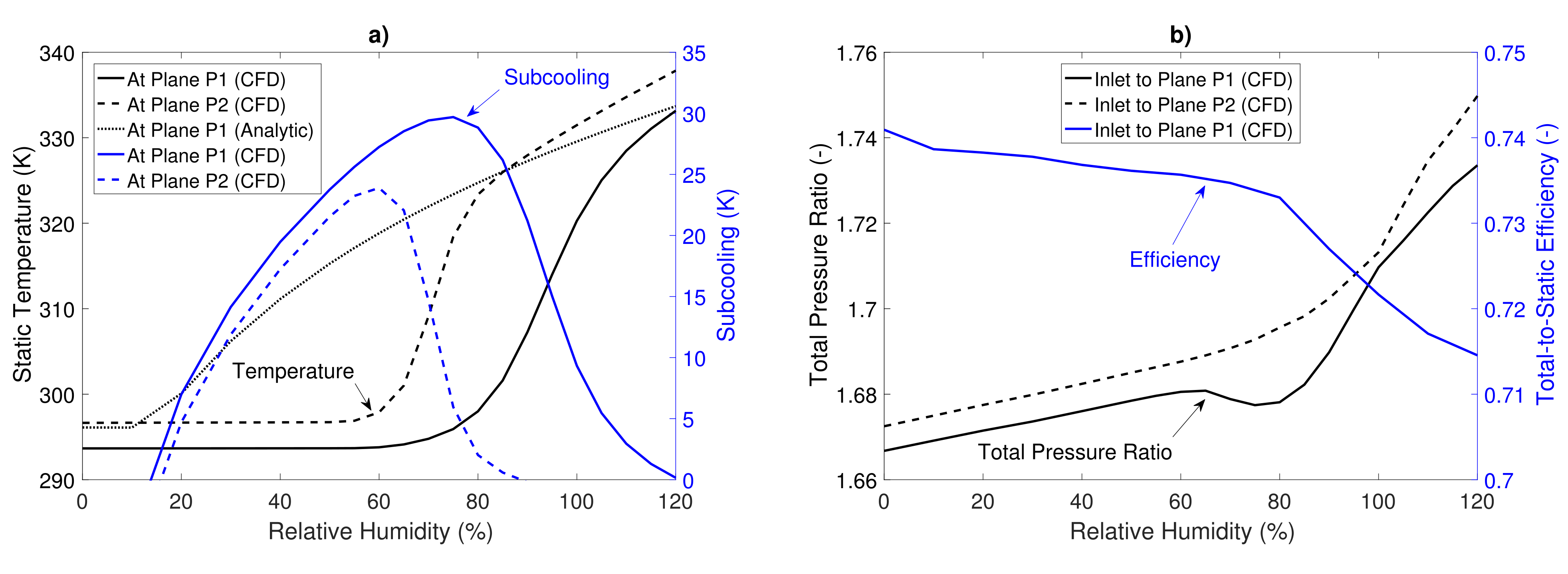
Figure 4a shows the area-averaged static temperature and subcooling at the above planes, P1 (solid lines) and P2 (dashed lines), plotted against the relative humidity at the stator inlet. The static temperatures (black) calculated with CFD appear to be constant between 0% and 60% relative humidity. Simultaneously, the flow subcools (blue) due to the absence of significant nucleation and condensation. Plane P1 is closer to the rotor than plane P2 and the velocity in plane P1 is higher. Thus, the static temperature in plane P1 is lower and the subcooling is larger. Above 60% relative humidity, an increasing number of nuclei are formed and the intensifying condensation reduces the subcooling. As the relative humidity reaches 80%, the static temperature in plane P2 rises by 25 K and the subcooling tends to zero. As will be shown later, a further increase in relative humidity shifts the nucleation zones upstream. This is the reason why the temperature rise and subcooling reduction in plane P1 take place at a higher relative humidity than in plane P2. The larger maximum subcooling in plane P1 than in plane P2 is due to the smaller distance between the plane P1 and the nucleation zones in the rotor. Above 85% relative humidity, the flow in plane P2 is in thermodynamic equilibrium. Therefore, no subcooling can be reversed and the temperature rise is less steep. The behaviour in plane P1 is similar but shifted to a higher relative humidity. At 120% relative humidity, the static temperature in plane P2 near the outlet almost reaches the static temperature at the stator inlet. The dotted line represents the analytically calculated temperature in plane P1 assuming thermodynamic equilibrium. The analytical calculation is based on the approach of Roumeliotis and Mathioudakis [
32]. Here, the expansion is modelled as a split process: First, the expansion was carried out with an isentropic efficiency while neglecting condensation. Second, isentropic condensation in a parallel duct led to equilibrium conditions. Discrepancies in the CFD results at 0% relative humidity result from the analytically assumed axial throughflow. The large differences between analytical and CFD results for relative humidities between 20% and 110% show the importance of considering the subcooling of the water vapour.
Figure 4b shows the total pressure ratios (black) between the stator inlet and planes P1 or P2, respectively. The total pressure ratio increases linearly in both planes from 0% to 60% relative humidity due to the changing gas mixture. Above 60% relative humidity, this effect is superimposed by thermal throttling due to the condensation. At 75% relative humidity, the main condensation zone with its local pressure increase is located right in plane P1. This causes the local minimum of the total pressure ratio at that humidity.
Figure 4b also shows the total-to-static efficiency (blue) calculated between the stator inlet and plane P1. The release of latent heat results in a distortion of all characteristic values dependent on temperature and enthalpy. Thus, the efficiency is calculated with the turbine power, which is based on the torque. The total-to-static efficiency is given by
with the output power
P, the massflow
and the isentropic total-to-static enthalpy difference
. The latter was evaluated by assuming an ideal gas and a constant ratio of specific heats
. This yields
with the index 0 indicating the stator inlet and the index 2 being the rotor outlet.
was evaluated at the stator inlet in order to avoid the influence of condensation and to ensure consistency. It can be seen that up to 80% relative humidity, efficiency decreases slightly by 0.8%. Between 80% and 120% relative humidity, the efficiency drops by almost 2% due to condensation. Several detrimental effects such as wall films and droplet impingement are not taken into account in these simulations. Therefore, the efficiency is expected to be worse in reality. The power output of the turbine increases almost linearly by 13% between 0% and 120% relative humidity due to the changed gas mixture. In multistage applications, power output can benefit significantly from condensation. The reason for this is the raised turbine inlet temperature of later stages compared to a dry flow.
5. Analysis of the Flow Phenomena
In this section, the influence of the condensation phenomena on the turbine flow is analysed. No condensation takes place in the stator. The stator flow is therefore only slightly influenced by the changing gas mixture and the above mentioned thermal throttling due to condensation downstream. However, the stator tip gap induces a vortex which affects the rotor flow. The frozen rotor approach leads to varying impacts of the stator on the rotor flow depending on the blade position. However, since 4/13 of the full annulus were calculated, representative results can be assumed. In the following, only the rotor flow is examined further. A general analysis of flow phenomena in radial turbines was carried out by Marsan and Moreau [
33].
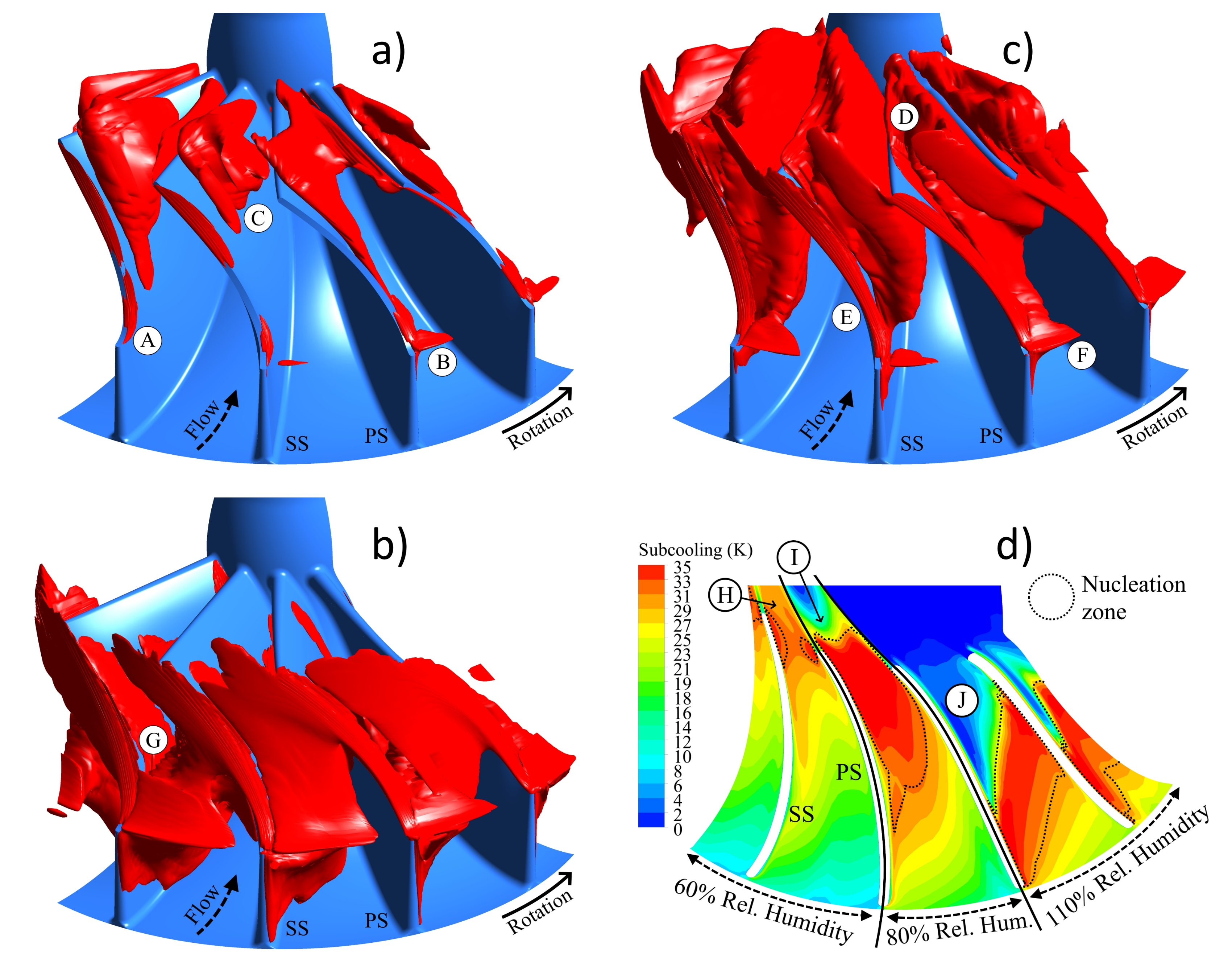
Figure 5a shows red isosurfaces wrapping the nucleation zones in the rotor at 60% relative humidity. Nucleation starts with sufficient subcooling which requires a low static pressure and/or a low static temperature. The accelerated flow in the blade tip gap (A) and near the shroud at the rotor entry (B) provides these conditions. The main flow shows nucleation at the end of the blade passage. However, only the faster sections towards the shroud are sufficiently subcooled for nucleation (C). The full cross section shows nucleation when the humidity is increased. The case of 80% relative humidity in
Figure 5b gives an example (D). The nucleation zones in the tip gap (E) and at the rotor entry (F) are intensified. The case of 110% relative humidity in
Figure 5c shows that the main channel nucleation (G) moves upstream with further increased relative humidity.
Figure 5d gives a contour plot of the subcooling at 50% normalized span. The plot is divided into three sections showing, from left to right, the results for the cases of 60%, 80% and 110% humidity.
The nucleation zones described above are marked with dotted lines. In all cases, subcooling starts further upstream on the suction side (SS) than on the pressure side (PS). This is obviously an effect of the lower pressure on the suction side. For 60% relative humidity, the subcooling downstream of the small nucleation zones (H) decreases slowly. This can be attributed to flow deceleration. The nucleation is yet not sufficient for significant condensation. For 80% relative humidity, the rapid subcooling decrease downstream of the nucleation zone (I) is caused by condensation. In the case of 110% humidity, the subcooling decrease (J) becomes even stronger. The higher humidity of this case also intensifies the nucleation/condensation phenomenon and thus shortens the streamwise extension of the nucleation zone.
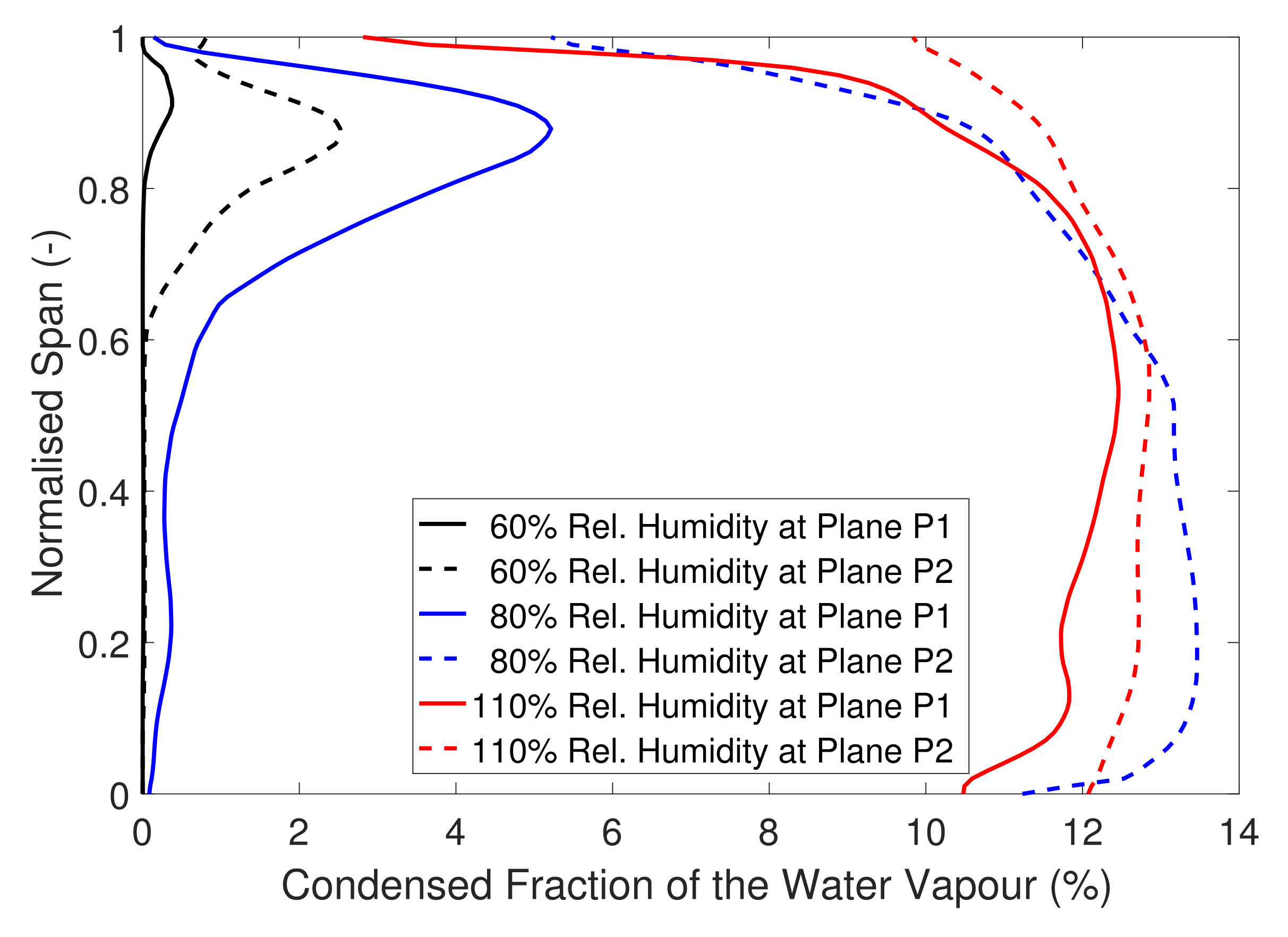
Figure 6 shows fractions of condensed water vapour plotted against the normalised span for three different levels of humidity. The results are circumferentially averaged in the planes P1 and P2 introduced above. At 60% relative humidity, condensation occurs only at 90% normalised span. This condensed water stems from the droplets formed in the tip gap and rotor entry (see
Figure 5a, annotations A and B) and their subsequent growth in the tip vortex system. Due to continued condensation, the fraction in plane P2 is larger than in plane P1. At 80% relative humidity, significant condensation can be found in plane P1 near the shroud due to the same condensation process in the tip vortex system. In the main flow, nucleation is still in progress. Thus, only a slight fraction of water vapour has yet condensed. In plane P2, the main flow has reached thermodynamic equilibrium and about 13% of the water is condensed. Near the shroud, condensation is delayed due to the warmer boundary layer. The case with 110% humidity shows a higher percentage of condensed water in plane P1. This is clearly an effect of the further upstream nucleation zones (see
Figure 5c). Interestingly, in this case, about 13% of the water vapour present at the domain inlet is also condensed. Clearly, the condensation enthalpy release required to reverse the subcooling rises proportionally with the increasing humidity. This leads to a similar fraction of condensed water.
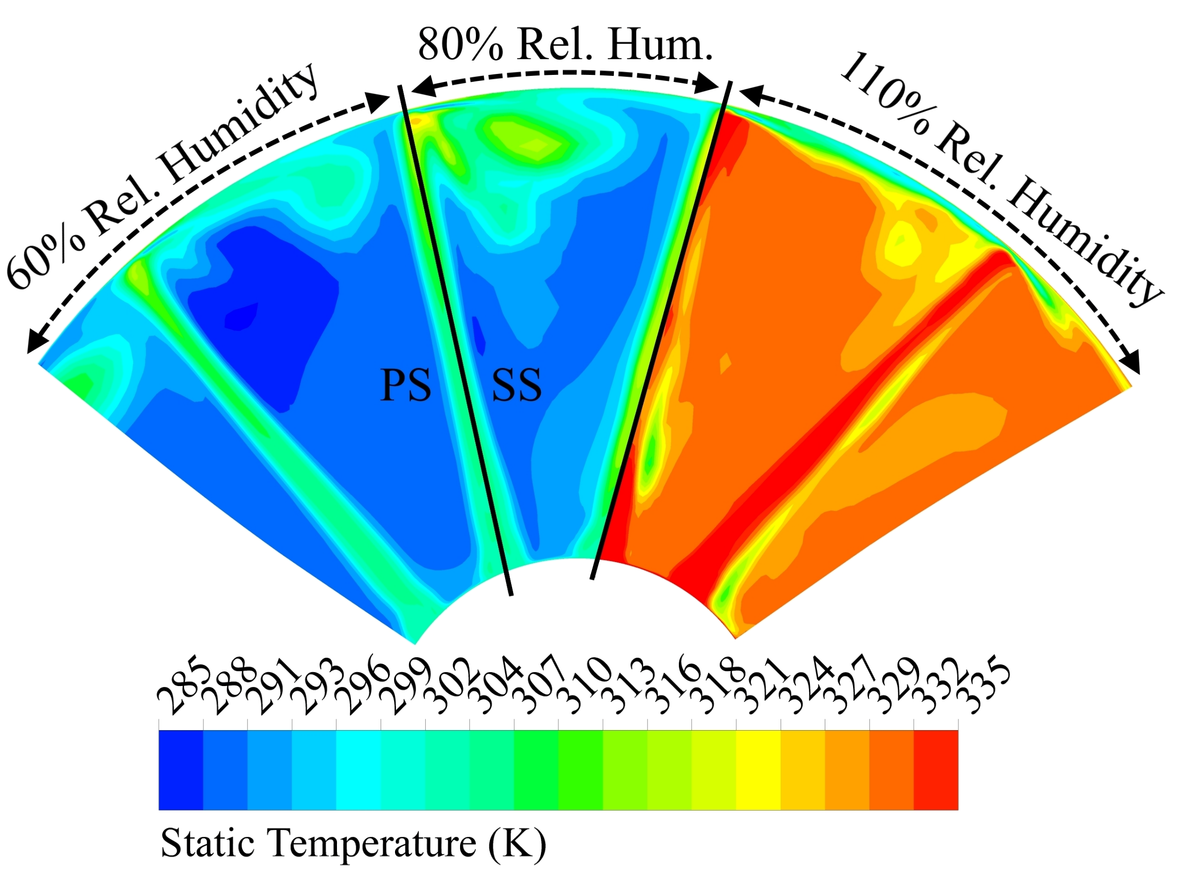
Figure 7 gives a contour plot of the static temperature in plane P1. The plot is divided into three sections showing, from left to right, the results for the cases with 60%, 80% and 110% humidity. A comparison of the cases of 60% and 80% relative humidity reveals a significantly warmer tip vortex system for the latter. This is due to the above mentioned increased condensation in the tip vortex system. The 110% relative humidity case shows a strongly increased temperature over the whole cross section due to condensation upstream.
Now the disperse droplet phase shall be analysed. Before discussing the results, it should be noted that a large number of nuclei formed in the tip gap are not able to grow after being transported out of the tip gap. This is due to the significantly higher subcooling in the tip gap. Schuster et al. [
34] reported this phenomenon earlier. In the following results, these droplets are omitted. In
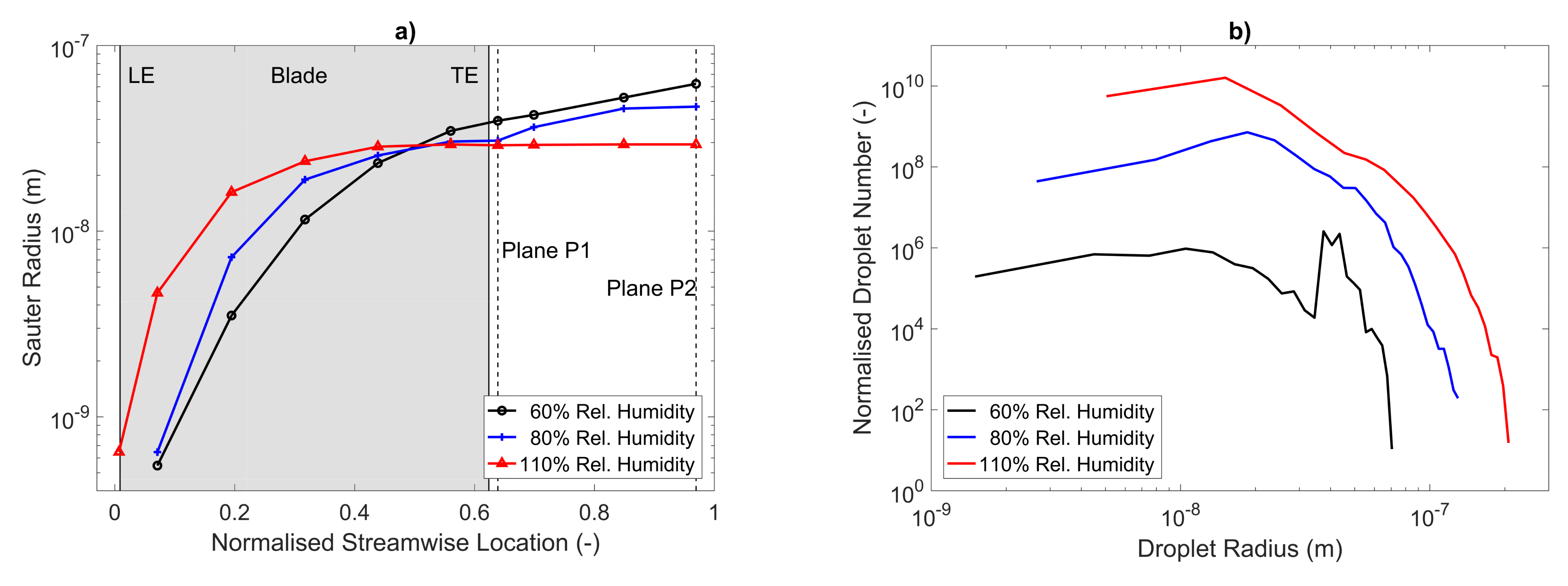
Figure 8a, the Sauter radius is plotted for three different humidities along the rotor flow. The leading edge (LE) and trailing edge (TE) of the blades are marked with solid vertical lines. The position of the planes P1 and P2 are marked with dashed vertical lines. In all three cases, the Sauter radius of the first nuclei is about 0.6 nm. The Sauter radii increase by about two orders of magnitude in the first half of the rotor domain. At higher humidity and thus higher subcooling at the rotor entry, the nuclei form slightly earlier and grow faster. Compared to cases with lower relative humidity, this leads to larger Sauter radii at the same normalised streamwise location. In the second half of the rotor domain, droplet growth is slowed down by the larger radius of the droplets and the reduced subcooling of the surrounding water vapour. Here, the case with a relative humidity of 60% has the largest Sauter radii. This is due to the fact that the droplets in this case stem mainly from the initial nucleation at the rotor entry and had a long time to grow. The absence of a large number of droplets that form later results in a large Sauter radius. In contrast, the other two cases have a large number of droplets formed in the main flow. A second factor limiting the further growth of the Sauter radius in these cases is the lower subcooling in the second half of the rotor domain.
Figure 8b shows the normalised droplet spectra for the same three cases. The spectra confirm the conclusions drawn from the Sauter radii. With increasing humidity, the number of smaller droplets grows over-proportionally, thus reducing the Sauter radius. The reason for this over-proportional growth is the large nucleation zones in the main flow, which produce a high number of droplets. Comparing the cases of 60% and 110% relative humidity, the total number of droplets is several orders of magnitude higher in the latter. The largest droplets always originate near the rotor entry. At 60% relative humidity, these large droplets stemming from the tip vortex system make up a substantial part of the spectrum and cause the significant peak at 40 nm. The largest droplets appear at 110% relative humidity and reach 200 nm.
Furthermore, it was found that the flow results are sensitive to the parameter
of Equation (
4), which defines the droplet growth rate and to a modification of the planar surface tension of water
. Larger values of
increase the droplet growth rate, which reduces the subcooling faster and thus shortens the nucleation zones. The onset of nucleation is not influenced by
. Smaller values of
reduce the work required to form a droplet and thus increase the nucleation rate and move the nucleation zones upstream. In addition to the presented validation with a supersonic nozzle flow, experimental measurements of the turbine under humid conditions would help to reduce uncertainties.
6. Conclusions
The aim of this study was to model and investigate the condensation phenomena in the radial turbine of a fuel cell turbocharger. First, the relevant theory of nucleation and condensation was briefly introduced. Subsequently, the numerical modelling with a Euler–Lagrange approach and a validation case of a supersonic nozzle were presented. The main results showed the condensation phenomena in the turbine rotor for varying humidity levels at the inlet. Condensation and a pronounced temperature increase of up to 30 K at the outlet were observed at 60% relative humidity and more at the inlet. At relative humidities above 80%, the turbine showed thermal throttling and reduced efficiency. It was found that nucleation starts first near the shroud at the rotor entry and in the tip gap, followed by nucleation in the main flow for higher humidity. In the blade passage, condensation is limited to the tip vortex system at inlet humidities below 80%. The Sauter radius of the droplets in the outflow is about 30 nm, with the largest droplets reaching 200 nm. The modelling parameters with the biggest impact are of Young’s growth law and a modification of the surface tension of water. In summary, humidity and condensation have a considerable influence on the thermodynamics of the turbine of a fuel cell turbocharger. Clearly, these effects must be taken into account in the future turbine design for fuel cell turbochargers. This applies in particular to multistage turbines. Here, the higher outlet temperature of the upstream stages significantly increases the power output of the downstream stages. It can also be concluded that condensation is always present in a typical automotive application. Even stronger condensation effects will occur in applications with higher pressure ratios, such as in aviation. Therefore, the fuel cell turbocharger and all downstream systems must be protected against erosion, corrosion and failure by liquid water. Regarding numerics, future studies should provide turbine performance maps for different degrees of humidity. The influence of the volute on the turbine flow should also be considered. Finally, detailed experimental measurements are needed to further validate this work.


