
Cantilevered Tandem Stator in Annular High Speed Test Rig


Institut für Luft- und Raumfahrt, Fachgebiet Luftfahrtantriebe, Technische Universität Berlin, 10247 Berlin, Germany
*
Authors to whom correspondence should be addressed.
Int. J. Turbomach. Propuls. Power 2022, 7(3), 24; https://0-doi-org.brum.beds.ac.uk/10.3390/ijtpp7030024
Submission received: 15 February 2022
/
Revised: 27 June 2022
/
Accepted: 14 July 2022
/
Published: 20 July 2022
Abstract
:The present paper investigates the aerodynamic performance of a cantilevered tandem stator based on experiments conducted within a high speed annular test rig at the Technische Universitaet Berlin. A tandem blade in this context describes a double rowed stator configuration where the turning of the incoming flow is split up between two blades arranged in succession. For evaluation purposes, a conventional single bladed stator is used as reference. To provide machine relevant boundary conditions of cantilevered stator assemblies, the moving hub wall is recreated by a rotating disk. Overall, the tandem stator is able to achieve higher flow turning while keeping the total pressure losses below those of a single stator. It is found that the tandem stator in general behaves similar to the conventional stator. When installed in cantilevered fashion, both stator types benefit considerably in terms of loss reduction. Without the hub clearance and therefore absence of the clearance flow, each of the configurations suffered from severe corner separation. The tandem stator responds more sensitively to change in clearance height.
Keywords:
axial compressor; stator; moving endwall; tandem blades; corner separation; clearance flow1. Introduction
Typically, there exist two installation types for axial compressor stators. A shrouded design, where both sides—hub and casing wall—of the stator are sealed off by platforms, respectively, walls. The second installation type is built in cantilevered fashion where the blade extends from the casing wall towards the hub featuring a radial gap between itself and the rotating rotor drum beneath. The choice for either of the designs is usually based on mechanical rather than aerodynamic considerations [1]. A shrouded blade is stiffer and less prone to failure triggered by aerodynamically induced vibration. Cantilevered stators on the other hand are distinctly cheaper to manufacture [2] and allow for smaller axial gaps between rotor and stator rows, shortening the overall compressor [3]. In-service compressors are often comprised of both types, where the first few compressor stages (with high aspect ratio blades) are equipped with shrouded and the remaining stages with cantilevered stators. In the following, a brief overview concerning the state of cantilevered stator research is given. The section will provide basic understanding of the fluid mechanical processes within a conventional stator passage. Those findings will later be addressed during the experiments in order to investigate as to what extent the same rules apply for a novel tandem stator.
The aerodynamic difference between the two installation types lies mainly in the kind of leakage flow. Leakage flow, which interferes with and disturbs the main flow within the stator row, is inevitable no matter the type of built as rotating and stationary components interchange. It is either in an axial direction through a seal beneath the shrouded stator or radially through the clearance at the hub for the cantilevered stator. In order to prevent blade failures by rub-in events, cantilevered stators usually feature larger clearances and therefore stronger and more pronounced leakage flow, which usually is accompanied by increased losses. However, based on aerodynamic quality of the stator alone, studies have shown that a cantilevered stator can be superior over its shrouded counterpart in terms of total pressure losses, as Lakshminarayana [4] and Dong [5] pointed out. An experimental study by Swoboda [6] on a multi stage low speed compressor with interchangeable stator rows confirms those observations. The aforementioned studies have in common that the respective stators under investigation show decreased total pressure losses when installed a cantilever compared to a shrouded installation. It is concluded that the reason for that behavior is the hub clearance flow, which opposes the near wall low momentum cross flow. The latter can thus not accumulate at the suction side corner and does not evoke a high loss corner separation. The loss-rich corner separation is suppressed. Other studies examined the interaction between the rotating hub wall and its adjacent stator clearance flow, as the rotating rotor drum plays a significant role in the behaviour of the stator clearance flow in general. From the stator’s point of view, the hub wall moves from the suction to the pressure side, pulling the hub leakage flow away from the suction side, deeper into the passage. Doukelis [7] investigated the influence of the rotational speed of the hub wall in a high speed annular cascade. It was found that the overall loss decreased and the turning increased continuously with raising of the wall speed. The energizing of the hub boundary layer and a more favorable inlet flow angle for the prismatic blades were identified as the underlying reasons. A rotating hub wall and its impact on the clearance vortex was numerically studied by Ventosa [8] for a linear cascade. Under the influence of the wall movement, the vortex separates from the suction side of the blade and is dragged towards the middle of the passage. Its mass flow through the clearance increases linearly with the rotational speed of the wall. It also has slight beneficial impact on the pressure loss distribution downstream from the passage as it stratifies it down to lower radial height. Similar observations were made by Koppe [9] in an experimental low speed axial compressor. The focus of the study lied on the skewing of the incoming boundary layer, which detaches the vortex from the suction side and lowers overall total pressure losses. Here, the positive impact of the clearance vortex on the overall pressure loss distribution over the shrouded blade is non-apparent. Worse still, the total pressure losses increased when cantilevered was installed. As mentioned, the benefit of the clearance flow is that it suppresses high loss corner separations, which can be advantageous. In the study mentioned, only very few signs of a corner separation are identifiable. There is little to no corner separation to suppress the total pressure losses’ increase due to the dissipating properties of the clearance vortex.
Summarizing the findings of the previously discussed studies, it can be said that the motion of the hub wall has two main effects on the adjacent flow. First, it does skew the boundary layer upstream from the inlet plane of the stator. Secondly, it amplifies the clearance flow through the stator hub gap. Both effects are consequences of the hub walls’ dragging effect on the viscous near wall flow. As a result, the flow upstream from the passage features a velocity component, which opposes the low energy cross flow from the pressure to the suction side and hence weakens the corner separation to some extent. It does, however, introduce a strong clearance vortex, which is of low momentum and total pressure. Losses can increase substantially in that region. Only if the suppressing effect of the near wall flow outweighs the disadvantage of the clearance vortex is a cantilevered stator design preferable.
It is unclear yet to what extent the observed behavior applies to double rowed stator vanes, which are so-called tandem blades. Little literature exists concerning cantilevered tandem stators. This gap of knowledge is what the present study aims to fill. The following section will give a brief overview of existing tandem literature in general.
The turning and therefore the aerodynamic loading within tandem blades is split up between two vanes, lined up in succession. Numerous studies in the past—based on two-dimensional or prismatic three-dimensional blades’ designs—were able to prove the tandem’s superiority over its reference single blade. Subsequent investigations reach machine relevant use cases. McGlumphy et al. [10] investigated the potential use of tandem blade rows for core compressor rotors. They developed a simple analytical design rule and supplied best practice guides to minimize the loss/loading ratio. He was able to show that tandem blade rows are superior to conventional designs under high aerodynamic loadings. The rules derived by McGlumphy et al. are widely used to design tandem blades, mostly stators. (The present study’s blade design is based upon those rules as well and will be explained later.) Tesch [11] studied the application of a tandem outlet guide vane in a low speed compressor where the turning and aerodynamic loading is beyond current in service compressors. Foret [12] investigated a tandem design variable stator vane in a transonic 1.5 stage compressor and compared it to a reference single blade. Again, the tandem design is distinguished by a higher pressure ratio and efficiency. The tandem features significantly fewer blades. Tandem stators in a low-speed 3.5 multistage environment have been studied by [13]. It was found that the front vane contributes to most of the wake losses under increased aerodynamic loads. There are few publications on cantilevered tandem stators, like the one of Konrath [14]. Here, prismatic tandem blades are investigated within a high speed linear cascade, both as shrouded and cantilevered types. (The present study can be viewed as a progression of the aforementioned, which will later be shown in further detail, see Section 2.2) The investigations investigated the behavior of a tandem and its conventional reference stator under changing aerodynamic loads. The tandem blade shows superior aerodynamic performance in terms of flow turning and total pressure losses. The secondary flow formation at the vicinity of the hub, namely the gap vortices, causes significant increase of the total pressure losses compared to the shrouded design. To the knowledge of the author, only one publication numerically investigates a cantilevered tandem stator as part of a transonic compressor stage [15]. It is found that the performance of the tandem and stage is considerably less sensitive to the rear vanes’ hub clearance size. Furthermore, a rightly sized hub clearance is able to increase stall margin significantly.
Based on the literature, it can be summarized that conventional single blade stators benefit from its associated hub clearance flow under the condition of an otherwise strong hub corner separation. A cantilevered built is then preferable from an aerodynamic point of view. In the second part of the Introduction, it is shown that tandem stators in general are superior to conventional stators. The present study aims to clarify whether the same beneficial influence of the hub clearance flow, witnessed within a conventional single stator passage, applies to a novel tandem stator. This gap in knowledge is addressed below by presenting experimental results, providing initial insights to close it.
2. Test Facility and Methods
The goal of the present study is to transfer the research objectives of the aforementioned investigation [14] to a test environment with increased machine relevance. The tandem stator and its reference single design are therefore being investigated in an annular test section to account for radial pressure gradients and centrifugal forces. In addition, the influence on a moving hub endwall on the formation of the clearance vortexes and the accompanying losses are subject of the present study. A pre-skewing of the inlet boundary layer is not part of this experimental investigation.
2.1. Experimental Facility
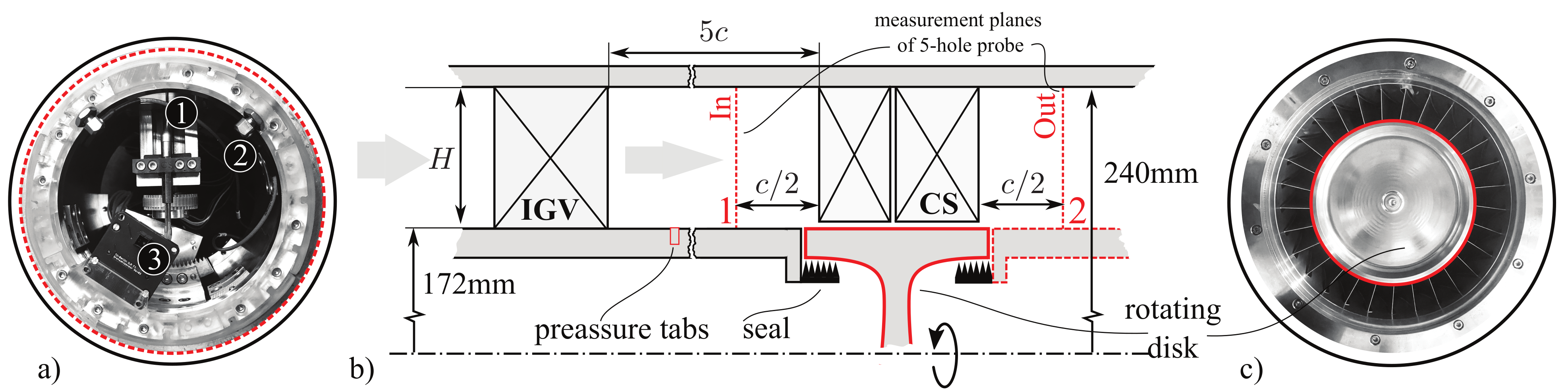
The experiments are conducted at the annular high speed test rig of the Chair of Aero Engines at the Technische Universität Berlin. Detailed explanation of the facility can be found in [16]. A schematic side view of the test section and its modifications is shown in Figure 1. One of the main new modules added as part of this project is the rotating disk, emulating a moving hub wall beneath the stator cascade. The disk has been analytically designed to be one of uniform strength. A subsequent verification by means of a finite element method computation confirmed the structural integrity of the disk at the highest intended rotational speeds. The hub surface of the disk extends of the compressor stator’s (CS) axial chord. The reason for the axial extent remains for future investigations, where the disk is equipped with pressure transducers. The housing of these requires the disk to extend beyond the trailing and leading edge of the blade above it.
A labyrinth seal is installed underneath the disk hub platform to suppress any leakage flow entering the test section. Even without the seal, leakage should, if any, be minimal since the hub section is closed in itself and sealed tight. Figure 1a shows the hub module downstream of the stator section. It contains the traverse system for the five hole probe (①). The latter is additively manufactured by Vectoflow. The head diameter measures 1.2 mm and, when fully extended, the probe’s area-wise blockage is equivalent to 3.2% of the CS passage, see Section 2.2. For reasons of bearing health monitoring, two eddy current sensors (②) are employed to measure the concentricity of the disk and its alteration over time. To measure the actual rotational speed of the disk, a photosensor is installed facing the disks’s front face. The measurement planes for in- and outflow conditions of the CS are positioned up- and downstream from the stator passage.
In its original design, the test section featured variable inlet guide vanes. In order to minimize endwall inhomogenity, due to penny gap vortices, they have been redesigned to become non-variable. The IGV’s are additively manufactured by in-house machines. The geometry, however, remains the same as described in [16]. The inflow conditions correspond to the operating points of the stator cascade, measured at the inlet plane (In, see Figure 1b), are shown in Figure 2. Those operating points will later be referred to by their corresponding mean line inlet flow angle , see Figure 2a. The Mach number distribution in Figure 2b shows fair uniformity in circumferential direction; no wake is identifiable. However, traces of the IGV’s secondary flow field are visible. Since both test cases of this study (see Section 2.2) are exposed to the same inflow conditions, the comparability of the two is still given. The sudden drop in inlet Mach number for all operating points in Figure 2c indicates a thick inlet boundary layer of about 12%. The distribution itself is in compliance with the one found by [16] and very similar to the distribution found in other annular cascades [17]. The Reynolds number of the test section is .
2.2. Blade Design
The goal of the present study is to transfer the research objectives of the aforementioned investigation [14] to the test environment described in the previous section. Based on that study, the intended flow turning the blades is within today’s loading limit of in service compressors and achievable by conventional blades. As tandem blades can easily handle higher loads, the intended turning is achievable with a significantly wider pitch. (This blade pitch to chord ratio is being taken over from the aforementioned investigation within the linear cascade.) Hence, aerodynamic blockage can be reduced drastically. In the following, the nomenclature, especially the one for tandem blades, refers to [18].
Since the inflow conditions vary with the channel height, the prismatic blade geometries used within the linear cascade of [14] cannot be utilized. Hence, a simple section-wise 2D redesign of the blades—reference and tandem—is carried out to account for the radially varying inflow angle . As the the inlet flow angle is assumed to change linearly with height (see Figure 2), three sections () at constant relative radial heights (, , ) are sufficient. Later, the blade geometry between those sections is spline interpolated. To ensure comparability to the linear case of the aforementioned project, the majority of the available cascade parameters are taken over. Since the emphasis of the present study lies upon the hub region, Section 1 inherits all those parameters. The sections above are adjusted to their corresponding inflow angle and the necessary widening of the passage due to the increasing diameter of the annulus. Some of the cascade parameters are shown in Figure 3a. Both stators are designed to feature a constant outflow angle of , hence the lesser turning near the casing. The reduction in inlet Mach number from previously 0.6 ([14]) to 0.4 is owed to the maximum feasible speed of the rotating disk, as will be discussed below. The inlet conditions at the chosen design point are shown as dashed red lines in Figure 2a. The blade geometries are generated using a self built Matlab code and are then numerically solved using the commercially available software Numeca FineTurbo. The design approach is quasi two-dimensional. A thin three-dimensional grid is used, which features slip walls at the top and the bottom such that the flow can be considered two-dimensional as only the blade surface is defined as no slip walls. The inlet turbulence is set to 5%. As turbulence closure, the SST model is being used with the additional transition model applied. Inlet mach number is set via the total pressure at the inlet and static pressure at the outlet.
Tandem specifics: Every section’s first iteration is based on McGlumphy’s simple design rule where the blade metal angles are calculated based on the D-factor using an equal load split of 0.5. Every section shall be designed in a way such that the DeHaller loading split is exactly 50/50 based on the numerical results, as are the tandem blades of [14]. In order to achieve this requirement, blade metal angles are adjusted accordingly based on the numerical result. The percent pitch is held constant at every height, which, in absolute terms, entails an opening of the gap with increasing radius.
Comparison of the reference and tandem stator: At the hub section S1, both the reference and the tandem blade show identical working range, identified by the breakdown of static pressure rise (Figure 3b). The working range of both stators increases with height as the aerodynamic loading decreases due to the lesser turning, which overcompensates for the wider pitch. The tandem stator shows slightly increased losses at S3 and vice versa at S1. This is in alignment with the general characteristics of tandem blades being superior to conventional blades at higher aerodynamic loads and inferior at lower [10]. To achieve those similar performance figures, the reference blade requires a 34% increase in blade count. Figure 3c shows the static pressure coefficient along the normalized axial chord. Both blades, with an early suction side peak, represent a state-of-the-art controlled diffusion airfoil. The acceleration of the flow through the tandem gap is visible by the second low pressure peak at the rear vane; see arrow.
To keep the absolute number of blades reasonably low and to simplify manufacturing, the blade’s aspect ratio is chosen to be 0.8. This increases the absolute thickness and in turn reduces cost. The short blade impairs the cascade’s overall performance as endwall losses will dominate. It does, however, still represent a sound research subject to investigate near hub wall flow phenomena.
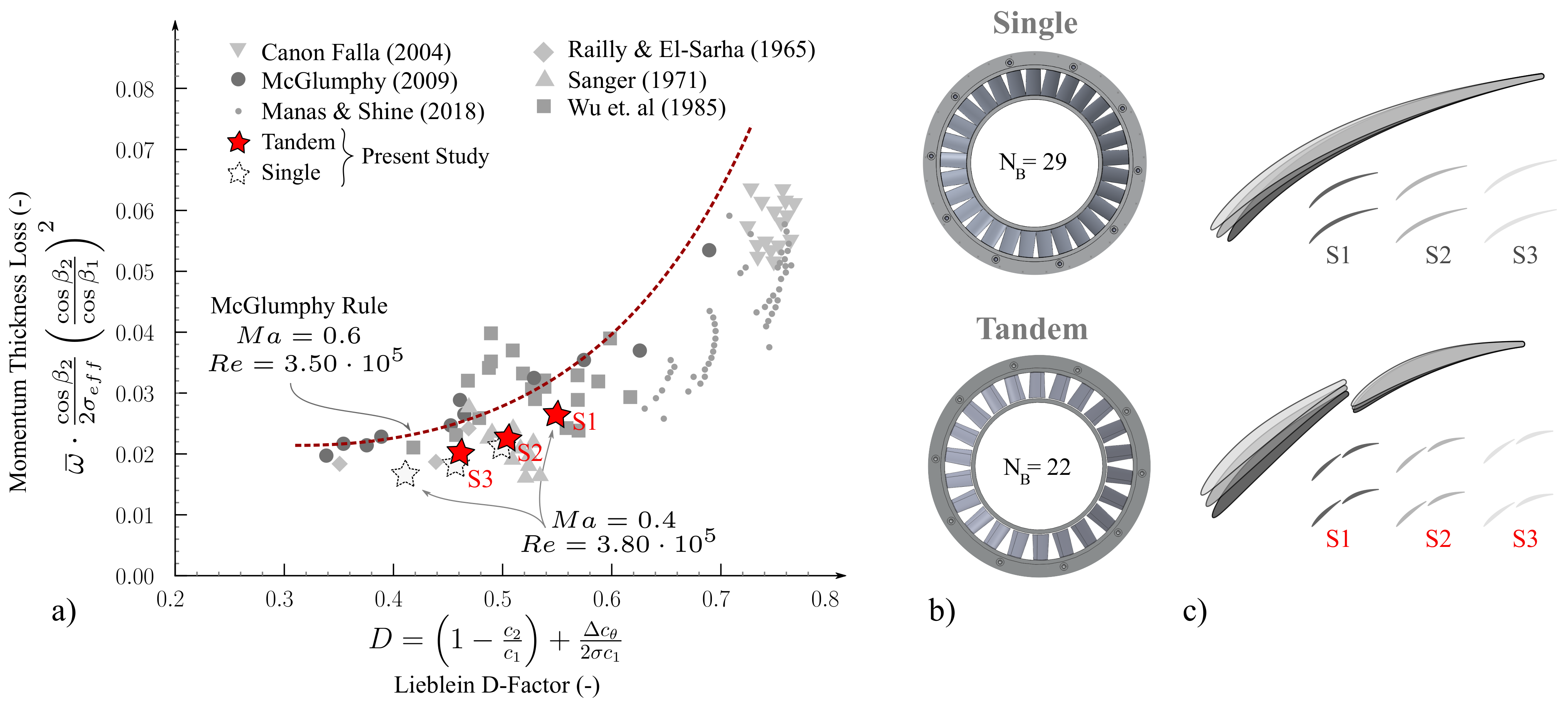
Figure 4a puts the final 2D blades into context. Compared to past investigations of two-dimensional tandem cascades, the blades of the present study show good agreement with the overall trend and lie within the boundaries of previous studies. They are overall moderately loaded with the hub sections exhibiting the highest Lieblein D-Factor. The tandem lift split based on the diffusion factor for sections S1, S2 and S3 is . The lift split based on the DeHaller number is for all sections. Figure 4b shows a rear view of the CAD model of the finalized stator cascades and the evident difference in blade count. The results of the 2D design process for both reference and tandem is shown in Figure 4c. The downstream similarities of each blade profile are due to the 15 outflow angle design choice. The absolute opening of the tandem gap, as described above, is clearly visible, as is the overall wider passage width compared to the reference.
Both of the blade variants are manufactured in four different versions. A gap-less stator represents an idealized shrouded stator without any leakage in axial direction through a seal beneath. Then, there are three cantilevered blades for each design featuring a 1%, 2% and 3% hub clearance based on the absolute chord length ().
2.3. Measurement Techniques and Data Reduction
The total pressure losses and flow angles are, if integrated, mass flow averaged. Losses known as denote the circumstantially averaged total pressure loss. denotes the fully integrated—in circumferential and spanwise direction—total pressure loss. The same applies for the flow angle .
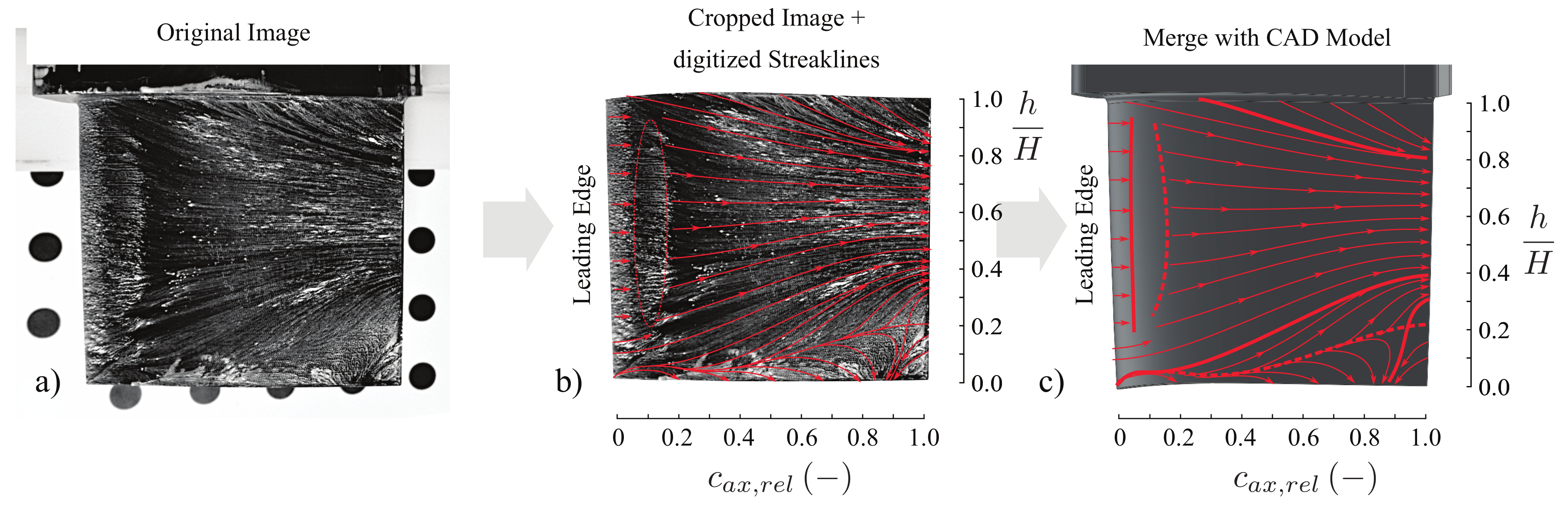
Figure 5 depicts how oil flow patterns on surfaces of blades and stationary walls are digitized. The sequence of steps followed are based on the ones described in [24]. The initial picture (a) is taken such that the camera faces the individual blade in its correct stagger angle, representing the meridional view of the stator row. Then, the streaklines are generated following the oil flow patterns (b) and subsequently critical lines—separation and attachment lines—are identified and displayed accordingly (c). For reasons of clarity and to highlight important areas of near wall flow features, only the fully digitized end results are presented.
In a real world axial compressor, the rotor drum rotates beneath the cantilevered stator, acting on the near-wall flow, altering the clearance vortex’ orientation. Here, the hub wall movement is recreated through the use of a disk rotating underneath the stator cascade. To reproduce engine relevant conditions, the drum’s rotating speed is calculated based on the nondimensional flow coefficient . Meanline levels for the throughflow coefficient of axial compressors usually range from . Based on this, the test section is treated as if a rotor precedes the stator section to calculate at which rotational speed this rotor would spin. As the meanline inflow, axial velocity is measured at 90 m/s and, with an intended at the design point, the disk needs to spin at 15,000 rpm. See Equation and for full derivation.
The measurement of the axial velocity has taken place, again, half a chord in front of the stator section at position 1, shown in Figure 1. Subsequently, the corresponding revolutions per minute can be derived through the following relationship:
In real life compressors, the relationship between the change of and the change of stator inlet angle follows a specific and individual correlation. Since this relationship cannot be modeled accurately without an actual rotor at hand, the rotational speed is held constant for different inlet angles. Still, the overall trend of in service machines is satisfied, as lower ’s lead to steeper stator inlet angles, as is the case for the datum investigation.
The abbreviations used below depict the blade type (S for single, T for tandem) and the gap size (0,1,2,3) in percent (P) of chord. Within the following, a notated hub clearance imperatively presupposes a rotating hub wall. A stationary hub wall is not part of the present paper.
The grid for downstream performance measurements of the tandem and single stator cascade spans 17 × 31 and 13 × 31 measurement points, respectively.
3. Results
In the following sections, both stator types are compared to each other based on oil flow visualization and flow quantities derived from five hole probe measurements downstream of the respective stator cascades.
3.1. Surface Flow
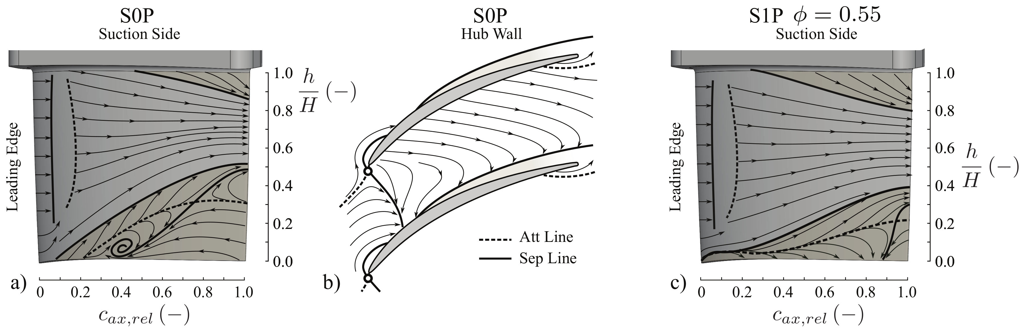
An initial impression of the secondary flow developing within in the single stator passage is shown in Figure 6. Here, subfigures (a) and (b) depict the gapless version at the design point.
Although the inlet flow angle (see Figure 2a) matches the design intend closely, the suction side features a substantial region of separation. It extends up to 50% span at the trailing edge and contracts the rest of the flow, forcing it towards the casing. The streakline patterns on the hub wall in part (b) reveal how a strong crossflow from pressure to suction side dominates the hub section. The corner separation itself extends only marginally into the circumferential direction and—at least near the wall—seems to be spatially bound to the suction side. All in all, the streakline patterns indicate a highly loaded hub region.
Under the influence of the rotating wall and with a 1% hub clearance, the pattern does change in part. Within the first 10% of the axial chord, traces of the formed clearance vortex are visible, which transition into the corner separation. The separation on the suction side starts noticeably more gradual and extends to now only 40% span at the trailing edge. Similar observations were made by [14] albeit the static hub wall. The lesser contraction of the mid span flow leads to a slightly grown corner separation at the casing. Still, there is now a region of about 40% span with undisturbed flow conditions. The aerodynamic quality of the single stator evidently benefits from the clearance flow’s influence.
The tandem blade in Figure 7a features a large corner separation at the front vane, absent in the study of [14]. The rear vane in comparison seems rather undisturbed. Again, and similar to the single stator, the tip region shows less signs of being aerodynamically overloaded, very little signs of backflow near the trailing edges are observable. On the contrary, the hub wall features a distinct focus point near the trailing edge of the front vane, which can be assigned to the separation at its corresponding suction side. This fluid region extends downstream throughout the whole passage, indicating strongly developed secondary flows within the passage. Comparing these results to the literature, it seems that the front vane’s loading exceeds the one of the rear vane significantly as Schluer [25] observes similar streakline pattern for a tandem configuration of asymmetric lift split, whereas the lift split of the lower section of the present tandem by design is close to equality (). Possible reasons for that will be discussed later. In part (c) of the same figure, similar results as found for the single blade case can be observed. Traces of two clearance vortexes are visible near their corresponding leading edges. The regions which indicated corner separations at the hub are shrunk distinctively. As with the single and judging by the streakline pattern, the tandem stator does benefit from a cantilevered installation at the design operating point. The laminar separation bubble is present for both stator types and has been observed in the linear cascade by Konrath [14] as well. It does not change location under the influence of the clearance flow.
3.2. Total Pressure Losses
The total pressure loss distributions for the design point are shown in Figure 8. The downstream plane of the single stator is characterized by a large area of low momentum fluid. It can be assigned to the severe corner separation seen in Figure 6a. The radial extension is in compliance with what is seen in the oil flow pictures. Towards the hub wall, the high loss region is being constricted and in closer vicinity to the suction side, confirming the oil flow patterns. Under the influence of the rotating hub wall in part (b), the area associated with the corner separation shrunk, both in radial and circumferential directions. However, near the hub wall, lower energy fluid now transitions into the neighboring passage uninterrupted, occupying the entire hub area. The total pressure loss distribution of the tandem (c) without any hub clearance in comparison is characterized by a larger area of low energy fluid, which extends to over 50% of the blade’s height. The secondary flow feature, which is responsible for this large area of disturbed flow, is most likely originating at the front vane since it shows more definite signs of corner separation; see Figure 7. It grew considerably on its way through the passage as it only started out at about 25% blade height, based on the oil flow visualization. Again, similar observations are made by [14]. There are on the other hand large portions of the wider tandem passage which show clean airflow when compared to the single stator case. Furthermore, there is no trace of two blade wakes evident in the measurements, which, for a percent pitch of 91%, confirms the observations made by Heinrich [14,18]. This could also be due to the resolution of the five-hole-probe grid. The Single wake is thinner but features more pronounced total pressure losses. Part (d) of the figure shows that the aerodynamic quality of the tandem benefits from the clearance flow. The high loss area clearly decreased in size and changed shape, comparable in its behavior to the conventional stator.
In general, the single and the tandem stator distinguish themselves clearly from linear cascade experiments of [14] by their downstream loss distributions. The flow field is asymmetric and dominated by secondary flows. The diffusion levels in the lower parts of the blades are high, which causes the flow to separate and create an area of low momentum fluid. Around that volume, the mass flow gets rearranged and accelerated towards the casing, deloading the upper half of the blade, which shows little to no signs of overloading.
Figure 9 shows the integrated results of the downstream five hole probe measurements. Note that, due to the constant rotational speed of the disk at 15 krpm, the flow coefficient changes accordingly as the axial velocity at the inlet varies with . Below the design point, increases and decreases above DP, respectively. Despite the larger area of high loss, the tandem outperforms the single blade in terms of global values when installed without hub clearance (b,c). This is due to its ability to achieve the turning with fewer blades. Albeit the region of high losses is more pronounced for the tandem, there are fewer passages around the circumference. Under the influence of the clearance flow, the loss loops as a whole get offset to lower levels. A hub clearance of 1% performs best for single and tandem blades. Increasing the clearance height results in raised total pressure losses, which, at the design point, are still below its idealized gap-less stator configuration. Similar behavior is observed by Xiayi [26]. In the same study, it was also shown that properly shrouded stators, accompanied by axial leakage through the seal beneath, show higher total pressure losses than an idealized one. The positive clearance effect observed here might therefore be even more pronounced when compared to real life geometries.
The tandem blade benefits more from the hub clearance flow compared to the single stator, as it drops to lower loss values, which again might be due to the fact that the suppressed region of separation was more severe to begin with. The gains of inhibiting it are greater.
The clearance flow and its associated dissipative vortex increase the losses near the hub wall as can be seen in Figure 9a,d. In addition, the tandem reacts more sensitively to clearance height changes compared to the single.
Based on two exemplary points (B,A) within the operating range, the different considerations when choosing cantilevered stators over shrouded ones become evident. At point A in subFigure (c), the cantilevered tandem with 3% clearance is on par with the idealized gapless tandem. Reasons for that can be seen in Figure 10c,d. The clearance vortex suppresses the blade’s separation but itself causes a pronounced area of low total pressures resulting in very similar performance Figures. At point B in subFigure (b), it can be seen that the cantilevered single actually suffers from higher total pressure losses when installed with hub clearance of 3%. Figure 10a,b demonstrates why. The clearance vortex is not able to weaken the profound separation; quite the opposite, it increases losses near the hub wall. The diffusion levels of the whole lower part of the blade at this incidence angle exceed the limits of what the single stator is able to withstand. The clearance vortex only superimposes its dissipating characteristics to the near wall region.
3.3. Flow Turning
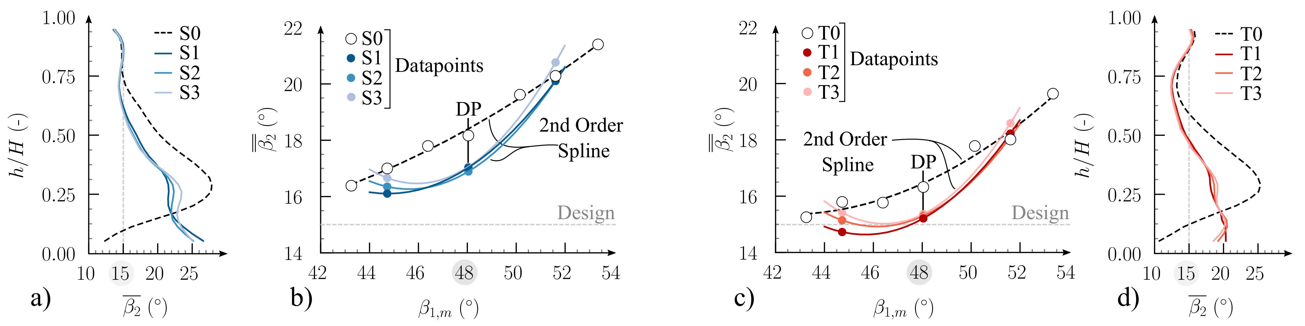
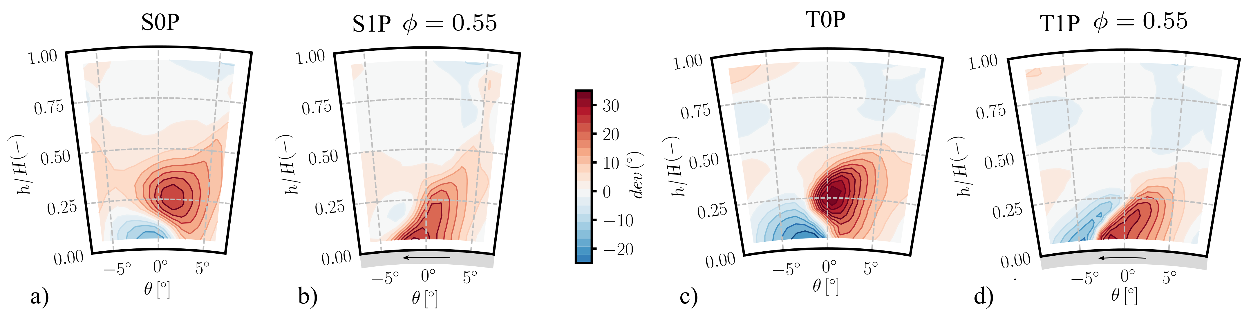
The behavior of the stator turning the incoming flow, see Figure 11, is comparable to the total pressure losses. Similar behavior as with the total pressure losses can be observed with the blades turning of the flow. Overall, the tandem stator achieves better turning. The increasing outflow angle with higher incidence levels starts more gradually for the tandem compared to the single stator. The increased turning originates not only in the lower half of the channel height, which again could be explained by undisturbed flow areas due to the much wider passage size (Figure 12a,c). The upper, cleaner part of the tandem also achieves higher turning compared to the single stator despite the CFD design’s results, Figure 11a,d. A similar discrepancy between numerical predictions and experimental result was observed by [14].
Reasons for the spreading out of the turning levels towards lower inflow angles can be explained by the stronger relative influence of the clearance vortex compared to the rest of the downstream flowfield. It increases in strength with increasing clearance height. With it, more massflow gets turned in a circumferential direction, away from the suction side, resulting in higher outflow angles and thus less turning. At the design point, its influence is much smaller compared to the gains achieved by inhibiting the regions of separation. In general, the hub clearance vortex worsens the turning characteristics of both stators significantly near the hub wall, which is expected (Figure 11a,b).
However, overall, the turning levels increase as the suppression of the large corner separation leads to a larger portion of the blade featuring clean flow, which in turn benefits the turning. At the design point, the tandem is near the design intent of a global 15 outflow angle. For all installation types, the tandem outperforms the conventional single stator in terms of integral turning levels. However, it does feature stronger outflow angle variation along the circumference within the region dominated by secondary flow, Figure 12—something which might impact the performance of a potentially following rotor.
3.4. Flow Blockage
A third parameter to evaluate and compare the two stator types to each other is flow blockage . It serves as a means to quantify the spatial extension of secondary flows and blade wakes and is an important quantity when it comes stage matching. Blockage describes the reduction in effective flow area and is defined as:
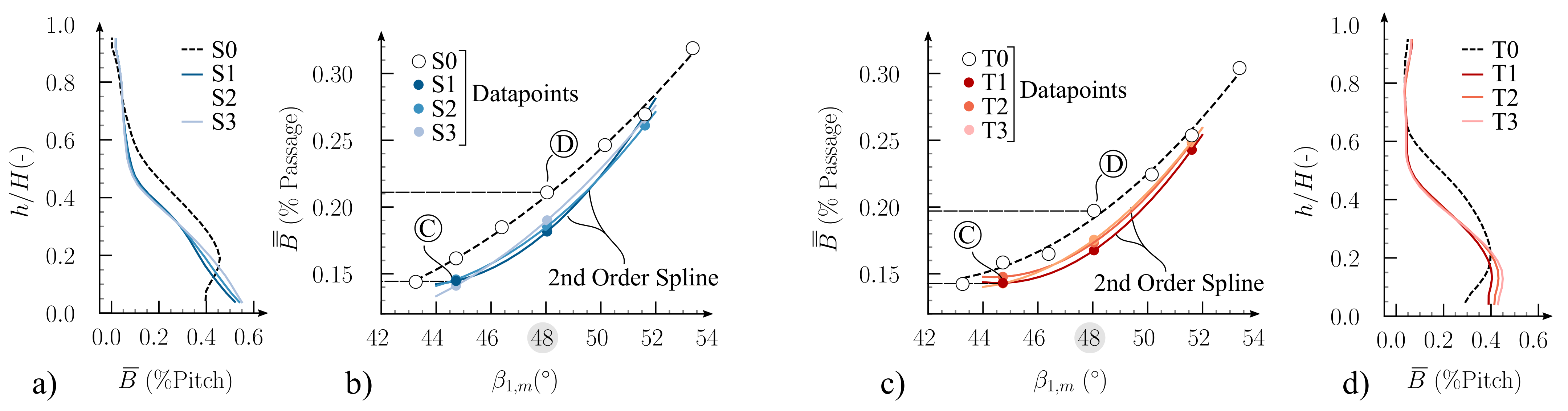
As stated by [27], this expression is analogous to the displacement thickness known from boundary layer theory. The difficulty, at least for experimental work, is to derive the in-viscid free stream velocity and density , . Within this work and as a robust approach, the ideal free stream velocity and density are presumed to increase linearly towards the hub. This assumption is based on the distribution shown in Figure 13a. Here, at operational point C with decreased aerodynamic loading, the flow blockage is low and most of the blade passage features clean air flow. It is assumed that the velocity distribution would continue this linear orientation if no areas of low momentum fluid in the vicinity of the hub would be present. SubFigure (a) also illustrates that, for both the single and the tandem stator, the axial velocity component and the density follow the same trend.
This simple model does not take the slight increase of axial velocity near the casing into account nor the presence of boundary layers at the casing or the hub. The absolute blockage values will therefore be shifted to slightly higher levels in that region. However, both stator types are subject to the same assumption and hence allow for comparison between each other. Sub Figure 13b,c show that the simple model is able to depict the main secondary flow structures.
It can be seen that the tandem stator, for this operational point C, features a more pronounced flow blockage at the hub. When integrating the B values in a circumferential direction, see Figure 13d, one can see that the single stator blocks 60% of the passage at the hub wall, whereas the tandem stator features values of just under 50% in the same region. In general, both stator types show similar blockage levels of the whole operational range, see Figure 14b,c. Both benefit greatly from the hub clearance flow as it suppresses the corner separation. The hub clearance size has less influence on the flow blockage as compared to the total pressure loss , see Figure 14a,d but overall reduces the blockage drastically apart from the near hub region. The effective flow area of the tandem stator increases more gradually compared to the single stator when installed without a hub clearance, see Figure 14b,c. Under lower aerodynamic loads (operational point C) and when installed with hub clearance, the tandem stator exhibits higher blockage levels than the single stator. Here, the clearance vortex of the tandem dominates the downstream flow field and is more strongly pronounced compared to the single stator.
4. Conclusions
Two annular stator cascades, a conventional single and a tandem blade, have been designed and tested in a high speed annular wind tunnel. The goal of the present study was to analyse the impact of two different mounting types, shrouded and cantilevered, for the two stator variants. Both blade types benefit greatly from the hub clearance flow and its suppressing impact on the otherwise dominating secondary flows near the hub wall. Overall, the tandem blade behaves in similar ways as its conventional reference blade, which is preferable as existing compressor designs can be more easily adapted to this new technology. In more detail, the tandem distinguishes itself through lower total pressure losses and higher overall turning levels. It benefits more from the clearance flow’s influence. Those performance gains however, are more sensitive to change in hub clearance size compared to the single. Both stators feature similar flow blockage levels over the operational range. Under decreased aerodynamic loads, the effective flow area of the tandem decreases more drastically when featuring hub clearance is installed. To obtain deeper understanding of which fluid mechanical phenomena are responsible for this behaviour, the results of further examinations within the passages by means of computational fluid dynamics and extended measurement techniques are currently evaluated.
Author Contributions
R.R. is the leading author of this paper; he performed the experiments on the test rig and evaluated both the experimentally and numerically acquired data. D.P. served as advisory throughout and contributed to the design process of the blades. Both authors contributed to the writing the paper. All authors have read and agreed to the published version of the manuscript.
Funding
This project (TI 992/1-1) is funded by the German Research Foundation (DFG).
Data Availability Statement
Not applicable.
Acknowledgments
The authors would like to thank the German Research Foundation (DFG) for funding of the investigations. Special thanks are due to Mario Eck and Jan Mihalyovics for their constant technical advice and guidance.
Conflicts of Interest
The authors declare no conflict of interest.
Abbreviations
| S | Single |
| T | Tandem |
| P | Clearance Height % Chord |
| AO | Axial Overlap |
| PP | Percent Pitch |
| IGV | Inlet Guide Vane |
| CS | Compressor Stator |
| Nomenclature | |
| Number of Blades | |
| B | Flow Blockage |
| c | Chord |
| M | Mach Number |
| h | Blade Height |
| H | Maximum Blade Height |
| M | Mach Number |
| Incidence Angle | |
| Static Pressure Coefficient | |
| Deviation Angle | |
| r | Radius |
| Circumferential Angle | |
| Total Pressure Loss | |
| Flow Angle | |
| Relative Pitch | |
| Relative Blade Thickness | |
| Flow Coefficient | |
| Subscripts | |
| rel | Referred to Maximum Value |
| eff | Effective Tandem Length |
| 1 | Inflow Value |
| 2 | Outflow Value |
References
- Wellborn, S.R.; Okiishi, T.H. The Influence of Shrouded Stator Cavity Flows on Multistage Compressor Performance. J. Turbomach. 1999, 121, 486–497. [Google Scholar] [CrossRef]
- Campobasso, M.S.; Mattheiss, A.; Wenger, U.; Amone, A.; Boncinelli, P. Complementary Use of CFD and Experimental Measurements to Assess the Impact of Shrouded and Cantilevered Stators in Axial Compressors. In Turbo Expo: Power for Land, Sea, and Air; American Society of Mechanical Engineers: New York, NY, USA, 1999; Volume 78583, p. V001T03A040. [Google Scholar] [CrossRef] [Green Version]
- Yoon, S.; Selmeier, R.; Cargill, P.; Wood, P. Effect of the Stator Hub Configuration and Stage Design Parameters on Aerodynamic Loss in Axial Compressors. J. Turbomach. 2015, 137, 091001. [Google Scholar] [CrossRef]
- Lakshminarayana, B.; Horlock, J. Leakage and Secondary Flows in Compressor Cascades; Reports and Memoranda/Aeronautical Research Council, Ministry of Technology, H.M. Stationery Office. 1967. Available online: https://reports.aerade.cranfield.ac.uk/handle/1826.2/4060 (accessed on 14 February 2022).
- Dong, Y.; Gallimore, S.J.; Hodson, H.P. Three-Dimensional Flows and Loss Reduction in Axial Compressors. J. Turbomach. 1987, 109, 354–361. [Google Scholar] [CrossRef]
- Swoboda, M.; Ivey, P.C.; Wenger, U.; Gümmer, V. An experimental examination of cantilevered and shrouded stators in a multistage axial compressor. In Turbo Expo: Power for Land, Sea, and Air; American Society of Mechanical Engineers: New York, NY, USA, 1998; Volume 78620, p. V001T01A075. [Google Scholar] [CrossRef] [Green Version]
- Doukelis, A.; Mathioudakis, K.; Papailiou, K. Hub Wall Rotation Influence on High-Speed Compressor Cascade Performance. J. Propuls. Power 2001, 17, 902–908. [Google Scholar] [CrossRef]
- Ventosa-Molina, J.; Lange, M.; Mailach, R.; Fröhlich, J. Study of Relative Endwall Motion Effects in a Compressor Cascade Through Direct Numerical Simulations. J. Turbomach. 2020, 143, 1–32. [Google Scholar] [CrossRef]
- Koppe, B.; Lange, M.; Mailach, R. Influence of Boundary Layer Skew on the Tip Leakage Vortex of an Axial Compressor Stator. In Turbo Expo: Power for Land, Sea, and Air; American Society of Mechanical Engineers: New York, NY, USA, 2020; Volume 84065, p. V02AT32A061. [Google Scholar] [CrossRef]
- McGlumphy, J.; Ng, W.; Wellborn, S.; Kempf, S. 3D Numerical Investigation of Tandem Airfoils for a Core Compressor Rotor. J. Turbomach. 2010, 132, 031009. [Google Scholar] [CrossRef]
- Tesch, A.; Lange, M.; Vogeler, K.; Ortmanns, J.; Johann, E.; Gümmer, V. An experimental investigation of a tandem stator flow characteristic in a low speed axial research compressor. In Turbo Expo: Power for Land, Sea, and Air; American Society of Mechanical Engineers: New York, NY, USA, 2014; Volume 45608, p. V02AT37A029. [Google Scholar] [CrossRef]
- Foret, J.; Franke, D.; Klausmann, F.; Schiffer, H.P.; Becker, B.; Müller, H. Experimental Investigation of a Transonic Compressor with Variable Stator Vanes in Tandem Arrangement. In Proceedings of the Global Power and Propulsion Society, Virtual, 7–9 September 2020; pp. 7–9. [Google Scholar] [CrossRef]
- Hopfinger, M.; Gümmer, V. Preliminary Design of a Three-Stage Low-Speed Research Compressor Using Tandem Vanes. In Proceedings of the AIAA Propulsion and Energy 2019 Forum, Indianapolis, IN, USA, 19–22 August 2019. [Google Scholar] [CrossRef]
- Konrath, L.; Peitsch, D.; Heinrich, A. An analysis of the secondary flow around a tandem blade under the presence of a tip gap in a high-speed linear compressor cascade. In Turbo Expo: Power for Land, Sea, and Air; American Society of Mechanical Engineers: New York, NY, USA, 2020; Volume 84065, p. V02AT32A001. [Google Scholar] [CrossRef]
- Mao, X.; Liu, B.; Zhang, B. Hub clearance effects of a cantilevered tandem stator on the performance and flow behaviors in a small-scale axial flow compressor. Aerosp. Sci. Technol. 2019, 91, 219–230. [Google Scholar] [CrossRef]
- Beselt, C.; Eck, M.; Peitsch, D. Three-dimensional flow field in highly loaded compressor cascade. J. Turbomach. 2014, 136. [Google Scholar] [CrossRef]
- Schulz, H.D.; Gallus, H.D. Experimental Investigation of the Three-Dimensional Flow in an Annular Compressor Cascade. J. Turbomach. 1988, 110, 467–478. [Google Scholar] [CrossRef]
- Heinrich, A.; Tiedemann, C.; Peitsch, D. Experimental Investigations of the Aerodynamics of Highly Loaded Tandem Vanes in a High-Speed Stator Cascade. In Turbo Expo: Power for Land, Sea, and Air; American Society of Mechanical Engineers: New York, NY, USA, 2017; Volume 2A, p. V02AT39A005. [Google Scholar] [CrossRef]
- Payyappalli, M.; Shine, S.R. Characterization of Tandem Airfoil Configurations of Axial Compressors. Int. J. Turbo Jet-Engines 2018, 39, 167–181. [Google Scholar] [CrossRef]
- Falla, G.C. Numerical Investigation of the Flow in Tandem Compressor Cascades. Master’s Thesis, Vienna University of Technology, Vienna, Austria, 2004. [Google Scholar]
- Railly, J.W.; El-Sarha, M.E. Paper 19: An Investigation of the Flow through Tandem Cascades. Proc. Inst. Mech. Eng. Conf. Proc. 1965, 180, 66–73. [Google Scholar] [CrossRef]
- Guochuan, W.; Biaonan, Z.; Bingheng, G. Experimental Investigation of Tandem Blade Cascades with Double-Circular ARC Profiles. Int. J. Turbo Jet Engines 1988, 5, 163–170. [Google Scholar] [CrossRef]
- Sanger, N.L. Analytical Study of the Effects of Geometric Changes on the Flow Characteristics of Tandem-Bladed Compressor Stators; NASA: Washington, DC, USA, 1971. [Google Scholar]
- Eck, M.; Rückert, R.; Tüzüner, E.; Mihalyovics, J. Surface Flow Visualization Techniques. In Proceedings of the Wandnahe Strömung in Beschaufelungen von Turbomaschinen, Dresden, Germany, 28–29 January 2021. [Google Scholar] [CrossRef]
- Schluer, C.; Böhle, M.; Cagna, M. Numerical Investigation of the Secondary Flows and Losses in a High-Turning Tandem Compressor Cascade. In Proceedings of the 8th European Conference on Turbomachinery: Fluid Dynamics and Thermodynamics, Graz, Austria, 23–27 March 2009. [Google Scholar]
- Si, X.; Teng, J.; Qiang, X.; Feng, J. Different Effects of Cantilevered and Shrouded Stators on Axial Compressor Performance. In Turbo Expo: Power for Land, Sea, and Air; American Society of Mechanical Engineers: New York, NY, USA, 2017; Volume 2, p. V02AT39A007. [Google Scholar] [CrossRef]
- Suder, K.L. Blockage Development in a Transonic, Axial Compressor Rotor. J. Turbomach. 1998, 120, 465–476. [Google Scholar] [CrossRef]
Figure 1.
Overview of test facility and measurement equipment including the inlet guide vane (IGV) and the compressor stator section (CS). (a) photography of the hub module downstream of compressor stator, indicated by a dashed red line (five-hole-probe ①, eddy-current sensors ② and photo sensor ③ to compute the revolution speed of the disk); (b) schematic sideview of the test section; (c) photography downstream from the compressor stator section, including the rotating disk.

Figure 2.
Inflow conditions of the stator cascade. (a) inlet flow angle ; (b) inflow Mach number distribution at the design point; (c) circumferentially averaged inflow Mach number at inlet plane.
Figure 2.
Inflow conditions of the stator cascade. (a) inlet flow angle ; (b) inflow Mach number distribution at the design point; (c) circumferentially averaged inflow Mach number at inlet plane.

Figure 3.
Design parameters and results of the tandem- and reference blades. (a) cascade data as basis for blade design in Section 1, are based on [14]; (b) loss loops and static pressure rise of the three radial sections; (c) distribution over blade surface of both tandem and reference blade at hub-section S1 at the design point ().

Figure 4.
Overview of finalized, two dimensional stator sections. (a) Contextualization of the designed blades based on available data on 2D tandem blades, based on [10,19,20,21,22,23]; (b) CAD models of final cascades; (c) blade sections at the three heights .

Figure 5.
Illustration of the post processing of the oilflow pictures. (a) monochromatic photography of oil flow pattern in side view, blade is staggered accordingly; (b) cropped image with digitized streaklines; (c) vectorized streaklines transferred to the CAD model of the corresponding blade.
Figure 5.
Illustration of the post processing of the oilflow pictures. (a) monochromatic photography of oil flow pattern in side view, blade is staggered accordingly; (b) cropped image with digitized streaklines; (c) vectorized streaklines transferred to the CAD model of the corresponding blade.

Figure 6.
Digitized oil flow patterns for the single blade at design point. (a) no gap, blade view; (b) no gap, hub wall view; (c) 1% gap, rotating hub wall, blade view.
Figure 6.
Digitized oil flow patterns for the single blade at design point. (a) no gap, blade view; (b) no gap, hub wall view; (c) 1% gap, rotating hub wall, blade view.

Figure 7.
Digitized oil flow patterns for the tandem blade at design point. (a) no gap, blade view; (b) no gap, hub wall view; (c) 1% gap, rotating hub wall, blade view.
Figure 7.
Digitized oil flow patterns for the tandem blade at design point. (a) no gap, blade view; (b) no gap, hub wall view; (c) 1% gap, rotating hub wall, blade view.

Figure 8.
Total pressure loss distribution for single and tandem blade at design point. (a) single blade, no gap; (b) single blade, 1% gap, rotating hub wall; (c) tandem blade, no gap; (d) tandem blade, 1% gap rotating hub wall.
Figure 8.
Total pressure loss distribution for single and tandem blade at design point. (a) single blade, no gap; (b) single blade, 1% gap, rotating hub wall; (c) tandem blade, no gap; (d) tandem blade, 1% gap rotating hub wall.

Figure 9.
Total pressure loss of the two cascades.(a) circumferentially averaged total pressure loss downstream from the single blade at design point; (b) tandem blade total pressure loss under different inflow angles ; (c) tandem blade total pressure loss under different inflow angles ; (d) circumferentially averaged total pressure loss tandem blade at design point.

Figure 10.
Exemplary total pressure loss distributions aside the design point; see Figure 9 for operating points. (a) single blade, no gap; (b) single blade, 3% gap, rotating hub wall; (c) tandem blade, no gap; (d) tandem blade, 3% gap rotating hub wall.
Figure 10.
Exemplary total pressure loss distributions aside the design point; see Figure 9 for operating points. (a) single blade, no gap; (b) single blade, 3% gap, rotating hub wall; (c) tandem blade, no gap; (d) tandem blade, 3% gap rotating hub wall.

Figure 11.
Outflow angles of the two cascades. Intended design angle (a) circumferentially averaged outflow angle single blade at design point; (b) tandem blade outflow angle under different inflow angles ; (c) tandem blade outflow angle under different inflow angles ; (d) circumferentially averaged outflow angle tandem blade at design point.

Figure 12.
Deviation () distribution for single and tandem blade at design point. (a) single blade, no gap; (b) single blade, 1% gap, rotating hub wall; (c) tandem blade, no gap; (d) tandem blade, 1% gap rotating hub wall.
Figure 12.
Deviation () distribution for single and tandem blade at design point. (a) single blade, no gap; (b) single blade, 1% gap, rotating hub wall; (c) tandem blade, no gap; (d) tandem blade, 1% gap rotating hub wall.

Figure 13.
Calculation of Blockage. (a) axial velocity distribution downstream of the cascade at various points of operation; (b,c) B values of single and tandem cascade at operation point C; (d) resulting distribution along the span.
Figure 13.
Calculation of Blockage. (a) axial velocity distribution downstream of the cascade at various points of operation; (b,c) B values of single and tandem cascade at operation point C; (d) resulting distribution along the span.

Figure 14.
Flow Blockage characteristics of single and tandem stator. (a) Blockage of single cascade at design point under different hub clearances; (b) integral blockage values of single cascade at various aerodynamic loads; (c) integral blockage values of tandem cascade at various aerodynamic loads; (d) blockage of tandem cascade at the design point under different hub clearances.

Publisher’s Note: MDPI stays neutral with regard to jurisdictional claims in published maps and institutional affiliations. |
© 2021 by the authors. Licensee MDPI, Basel, Switzerland. This article is an open access article distributed under the terms and conditions of the Creative Commons Attribution (CC BY-NC-ND) license (https://creativecommons.org/licenses/by-nc-nd/4.0/).
Share and Cite
MDPI and ACS Style
Rückert, R.; Peitsch, D. Cantilevered Tandem Stator in Annular High Speed Test Rig. Int. J. Turbomach. Propuls. Power 2022, 7, 24. https://0-doi-org.brum.beds.ac.uk/10.3390/ijtpp7030024
AMA Style
Rückert R, Peitsch D. Cantilevered Tandem Stator in Annular High Speed Test Rig. International Journal of Turbomachinery, Propulsion and Power. 2022; 7(3):24. https://0-doi-org.brum.beds.ac.uk/10.3390/ijtpp7030024
Chicago/Turabian StyleRückert, Roland, and Dieter Peitsch. 2022. "Cantilevered Tandem Stator in Annular High Speed Test Rig" International Journal of Turbomachinery, Propulsion and Power 7, no. 3: 24. https://0-doi-org.brum.beds.ac.uk/10.3390/ijtpp7030024