
Design and Experimental Results of an Adaptive Fractional-Order Controller for a Quadrotor


Department of Automation, Faculty of Automation and Computer Science, Technical University of Cluj-Napoca, Memorandumului Str. 28, 400014 Cluj-Napoca, Romania
*
Author to whom correspondence should be addressed.
Fractal Fract. 2022, 6(4), 204; https://0-doi-org.brum.beds.ac.uk/10.3390/fractalfract6040204
Submission received: 17 February 2022
/
Revised: 20 March 2022
/
Accepted: 4 April 2022
/
Published: 6 April 2022
(This article belongs to the Special Issue Fractional Order Controllers: Design and Applications)
Abstract
:The use of multi-copter systems started to grow over the last years in various applications. The designed solutions require high stability and maneuverability. To fulfill these specifications, a robust control strategy must be designed and integrated. Focusing on this challenge, this research proposes an adaptive control design applied to a physical model of a quadrotor prototype. The proposed adaptive structure guarantees robustness, control flexibility, and stability to the whole process. The prototype components, structure, and laboratory testing equipment that are used to run the experiments are presented in this paper. The study is focused on the performance comparison of a classical PID controller and a fractional-order controller, which are both integrated into the adaptive scheme. Fractional-order controllers are preferred due to their recognized ability to increase the robustness of the overall closed-loop system. Furthermore, this work covers the design and the tuning method of this control approach. The research concludes with the actual results obtained for this comparative study that highlights the advantages of the fractional-order controller.
1. Introduction
The interest to integrate multi-copter systems into different types of aeronautical applications has increased in recent years due to their easy-to-fly readiness and maneuverability. These systems are widely used for video and photography data gathering in various domains or for aerial surveillance and monetarization of power plants, wind and solar parks, power lines, industrial parks, wildfires, or natural disasters. Search and rescue, refugee localization and first aid assistance represent the most frequent applications of these systems because of their fast response time and easy accessibility. A secondary category of applications is represented by glacial inspection, agriculture crops inspection and spraying, bridges and dam inspection, border patrol, excavation, site documentation, and goods delivery [1,2]. Such aerial vehicles have become widespread in various military and civilian applications. This has led to significant attention in designing advanced control algorithms for such systems in the last few years. This is also the underlining motivation for this research: to evaluate the operation of a quadrotor system using different types of control strategies by performing a series of tests and experiments on a laboratory prototype.
A series of testing models exist today [3,4], each with its very own set of advantages and disadvantages. The existing solutions on the market, designed as laboratory test systems, are usually used to simulate a particular performance and are usually expensive. This results in the need to design and build a custom-made laboratory set-up that would allow the implementation of various control strategies, including advanced control algorithms, as well as the experimental testing of these strategies in a wider range of flight scenarios. This represents the motivation behind the design of a custom-made quadrotor within the research lab of the authors. Regardless of the prototype used, the most challenging part in the control of such equipment comes from their physical complexity, strong inter-axes dependency, nonparametric uncertainties and susceptibility to serious disturbances.
In order to solve this complex demand by finding the optimal result, researchers created different control approaches, such as PID (Proportional, Integral and Derivative) control, adapted with image processing, adaptive control, sliding mode control, predictive control, feedback linearization, fuzzy logic, etc. [5]. A recent survey of fractional-order control algorithms applied to unmanned aerial vehicles is available in [6]. An attitude control application of a quadcopter using a neural network and sliding mode fractional-order controller is proposed in [7]. Another study [8] proposed the control of the pitch axis for a UAV by implementing a fractional order filter with a two-degrees-of-freedom PID controller. The lateral direction or roll axis control for a fixed-wing unmanned aerial vehicle with a PI fractional-order controller is proposed in [9,10] and the same approach applied to pitch control is described in [11] for a vertical takeoff and landing process. A path tracking control solution for a quadcopter is presented in [12], with an adaptive correction of weight parameters and a fractional-order sliding mode controller. In [13,14], the proposed solution to cope with uncertainty such as unmodelled dynamics and unknown parameters is a robust Hinf controller.
Even though several fractional-order algorithms have been applied to the control of multi-rotor systems, the current literature presents no valid result of this fractional-order controller used together with adaptive control. The novelty of this manuscript is related to the design, implementation and experimental validation of an adaptive fractional-order attitude controller of a custom-made quadrotor model designed in our laboratory. The design of the fractional-order adaptive controller originates from a previous experiment and the results obtained, which are presented in [5,6,7,8,9,10,11,12,13,14,15,16,17,18]. Further investigations in advanced fractional-order mathematics and calculus as applied to neural networks are covered in [19,20].
This study aims to identify an efficient and robust control solution and apply it to the proposed system. Therefore, this paper presents the results of a well-known and frequently used classical PID controller compared with advanced fractional order PID (FO-PID) controller. Fractional-order controllers are preferred due to their recognized ability to increase the robustness of the overall closed-loop system. Integrating a fractional-order controller into an adaptive control scheme provides robustness and flying adaptability to major disturbances to the whole process. Based on these results, a new control approach is suggested. The structure of the quadrotor system and testing stand, together with the proposed control algorithm and some preliminary results, has been presented in [21]. The results presented in the previous research are obtained by simulation using the mathematical model of the multi-rotor system. On the other hand, the results in the current work have been achieved through the physical experiments performed on the real model.
The paper is composed of five parts. An introduction is already covered by Section 1. In Section 2.1, the quadrotor prototype is presented. Section 2.2 focuses on the proposed control algorithm, while the results obtained on the physical system are shown in Section 3. The last section covers the conclusion of our study.
2. Materials and Methods
2.1. The Quadrotor Prototype
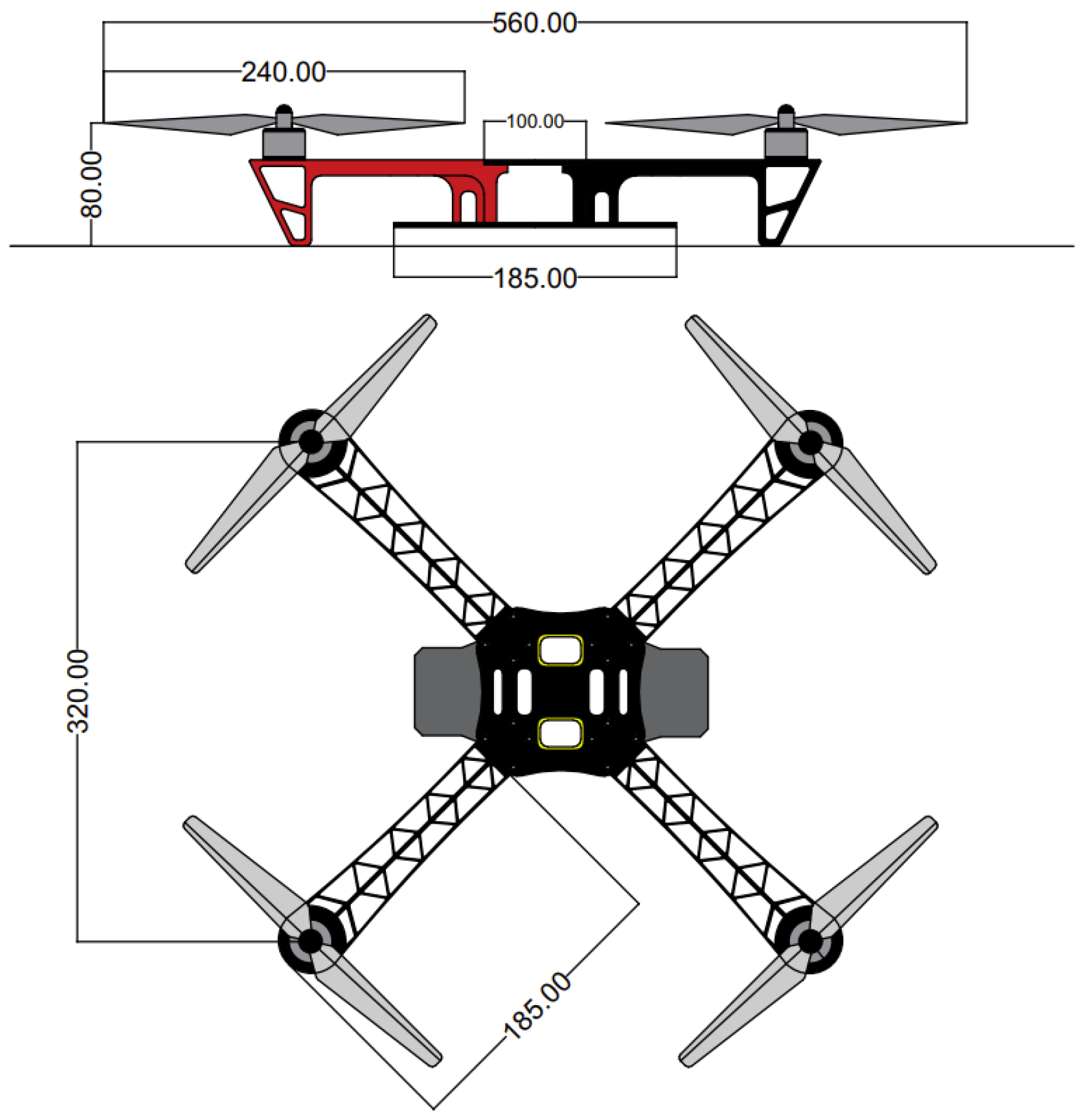
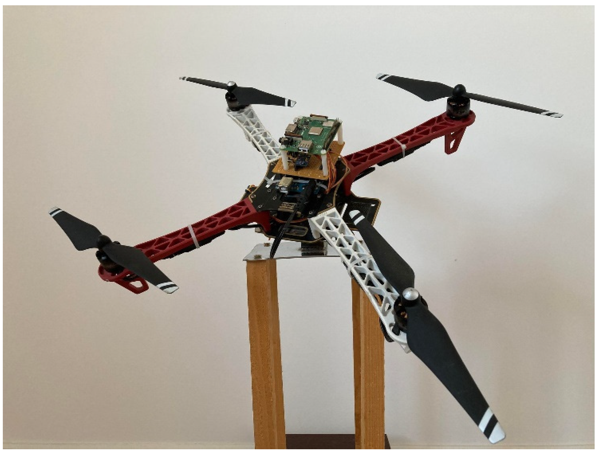
Figure 1 details the blueprint with the related dimensions (in mm) of the quadrotor, while the prototype on the testing stand is depicted in Figure 2. The experimental unit is used to design and physically validate the performances of the desired control strategy. Hence, the proper components and quadrotor parts have been chosen to fulfill the laboratory testing demands.
The body parts of the quadrotor system are available on the market and were acquired from a specialized manufacturer. The body frame of the DJI F450 [22] is made of plastic with a weight of 282 g. A set of four brushless DC motor DJI 2212’s [22] with 11.1–14.8 V input voltage, a diameter of 28 mm, and a weight of 56 g each are connected to the frame. To rotor, a DJI 9450 [22] propeller is connected with 28 mm in diameter, 127 mm propeller pitch, and 13 g weight. The angular velocity of each brushless motor is controlled by an electronic speed controller (ESC) DJI E300 [22] type, powered by an 11.1–14.8 V and 15 A power supply. The control of this driver is made using PPM (pulse-position modulation) with a frequency between 30 and 450 Hz. The weight of each ESC is 13 g. The power supply for this subsystem is a lithium-polymer (Li-Po) battery type DJI–PTM12 [22] with a 2200 mAh capacity and 11.1 V nominal voltage. This battery guarantees 15 min of flying time at 20 °C ambient temperature. A HobbyKind radio controller was used with six channels at 2.4 GHz frequency (type HK T6A V2) [22]. An Arduino UNO development board [22] was the microcontroller used to interact and control the components described above. In order to read the angular velocity and angular position, an MPU 9150 [17] inertia measurement sensor was connected to the microcontroller.
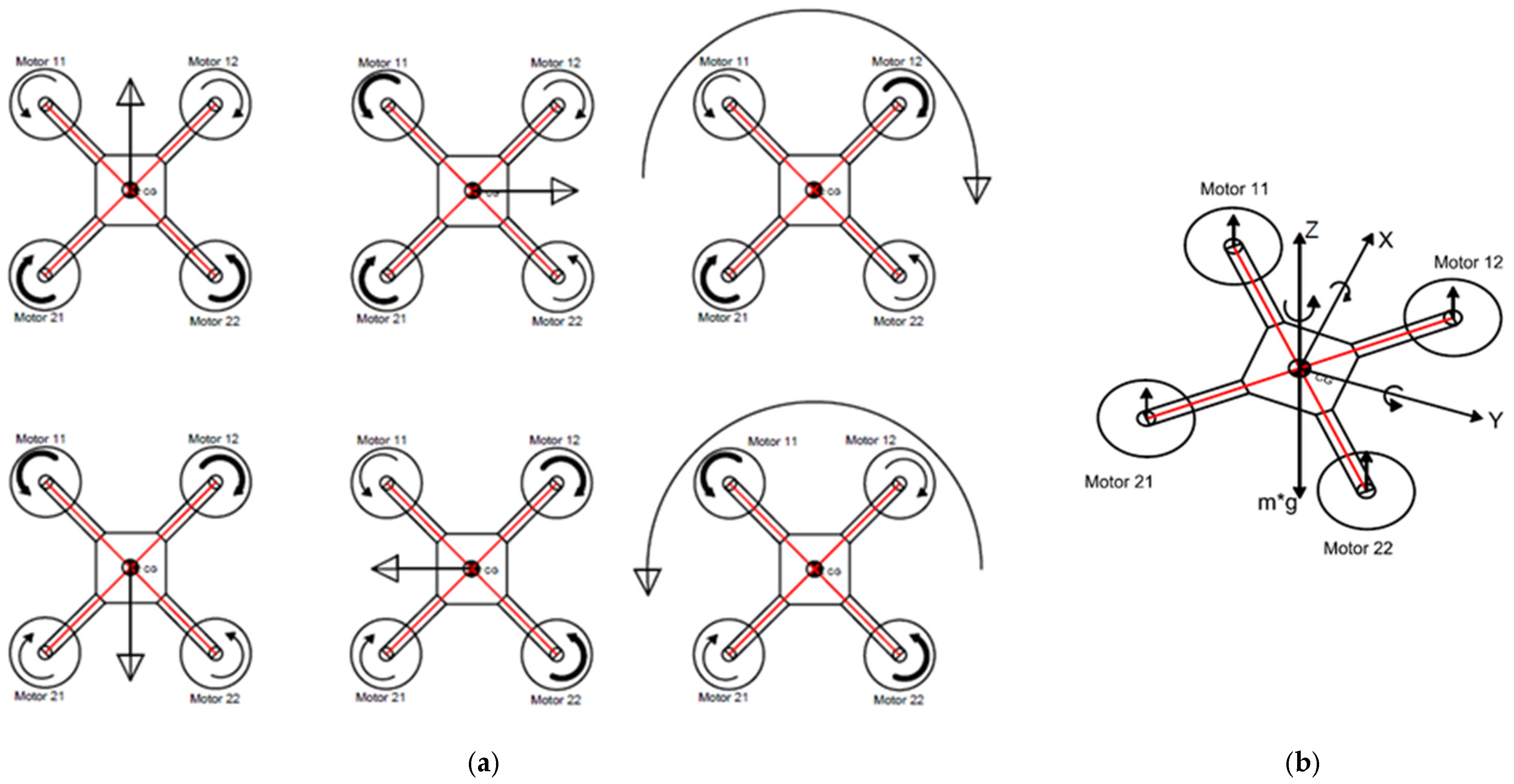
Figure 3a presents how the quadrotor system can move through space. By controlling the spinning velocity of each propeller, this movement can be performed. The quadrotor hovers when all four motors are generating equal vertical forces (which are generated by rotor angular velocity). In the case where movement through the air is required, the velocity should be increased or decreased to a corresponding pair of rotors. This difference will break the force balance, and the whole body will move in the desired direction in order to compensate for it. Figure 3b shows the angular positions and generated torques.
2.2. The Proposed Control Strategy
Based on general equations from [23], the following nonlinear mathematical system describes the dynamics of the quadrotor prototype:
where (ϕ), (θ) and (ψ) are the angular positions of axes x, y and z; (Ui), (i = 1, 2, 3, 4) are the torques around each axis. These torques are generated by changing the speed of the desired propeller; thus, the thrust force applied at the end of the quadrotor’s arm is modified. is the altitude input, which represents the sum of all lift forces created by each propeller motion. In order to control the orientation of the quadcopter’s body (U2, U3, U4), each motor velocity must be adjusted by the proposed control strategy. The moments of inertia around each axis are (Ixx), (Iyy) and (Izz). Because the mass is evenly distributed and the quadrotor is geometrically symmetric, then the assumption that Ixx = Iyy can be made. For this study, U1 was blocked, and the validation test stand allowed for only orientation movements.
Summarizing those above, the inputs (U) and outputs (Y) of the system will be:
where mij is the lift force generated by a specific DC motor, Rollrate () and Roll () are the angular velocity and position around X axis, Pitchrate () and Pitch () are the angular velocity and position around the Y-axis and Yawrate () is the angular velocity around Z-axis. As indicated in the mathematical model, the system is strongly coupled. A small change to any input of the system will directly impact the response of all outputs. These interactions can be reduced almost to 0 by designing a complex control structure. Additionally, external disturbances can easily destabilize the quadrotor or even render it unstable. Thus, each rotation axis should be controlled by a properly tuned and robust controller.
U = [U1 U2 U3 U4]
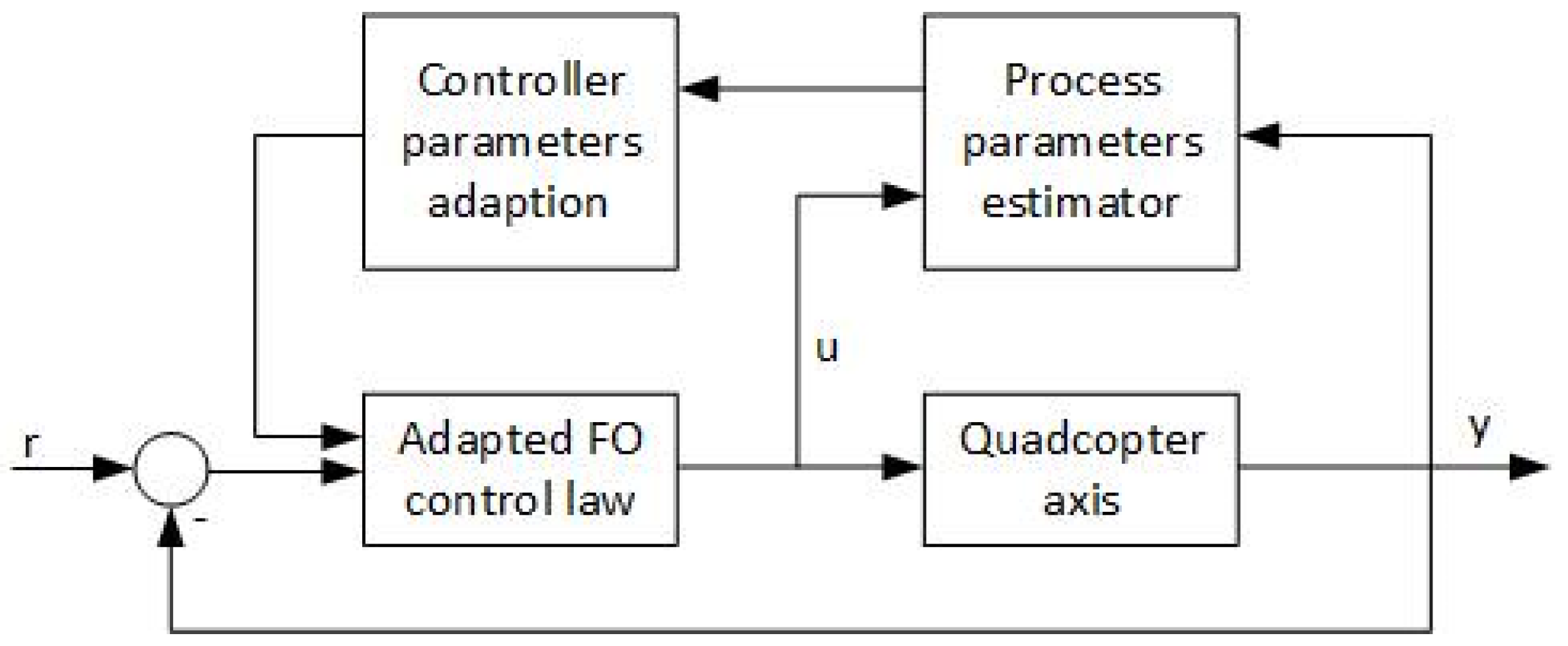
The suggested control algorithm is depicted in Figure 4. All process parameters can be estimated in real-time at each sampling time by the identification block, while the new controllers’ recursive equations are recalculated by the adaption block based on the newly identified process parameters. The identification block measures the input and the output of the system (on each rotational axis) and performs a parameter estimation using the recursive least squares parameter estimation algorithm with exponential data weighting [24]. Thus, model variations can be identified and the control parameter adjusted.
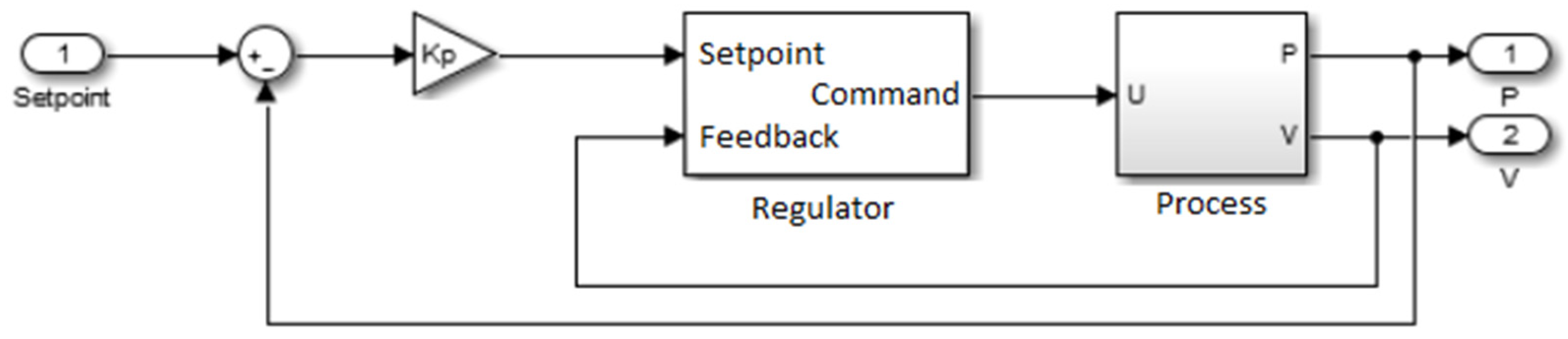
Moreover, the angular position is desired to be manipulated. Thus, using a cascaded-loop controller, this demand can be easily achieved. For each input–output loop in the quadrotor (as resulting from a decentralized approach), the proposed controller is applied to the velocity part of each process (in the inner loop), while a proportional gain is used as an angular position controller (external feedback loop). Figure 5 shows the cascade control loop used for this research.
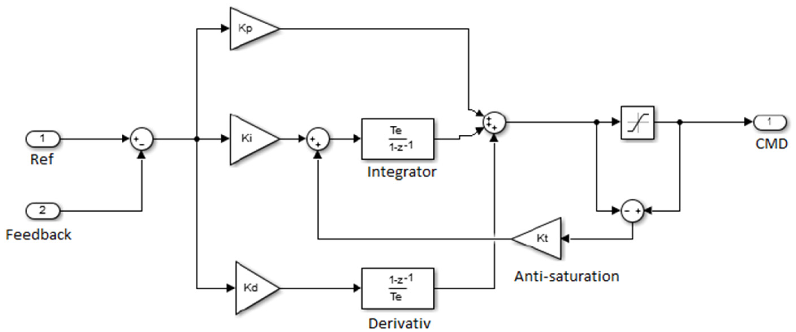
A classical PID controller is a good choice to control the angular velocity of each axis because it guarantees a fast response and a steady-state error. The only disadvantage is caused by the delay added from the integrator component to the control signal. When the control signal is saturated, it will remain so with the variation of the error signal for a short amount of time due to classical integral behavior. Thus, an anti-saturation action is proposed to correct this undesirable performance. The value of anti-saturation gain is computed using Equation (6).
The internal structure of the PID controller described above is presented in Figure 6.
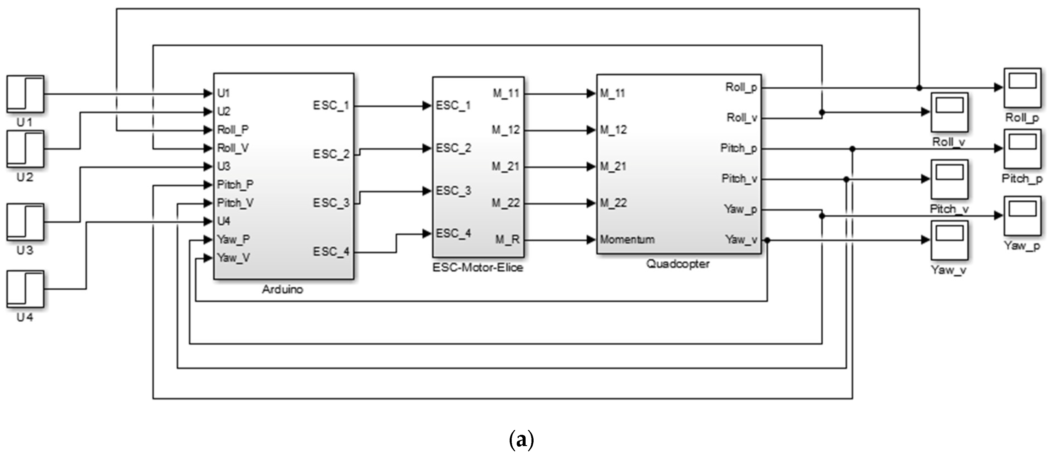
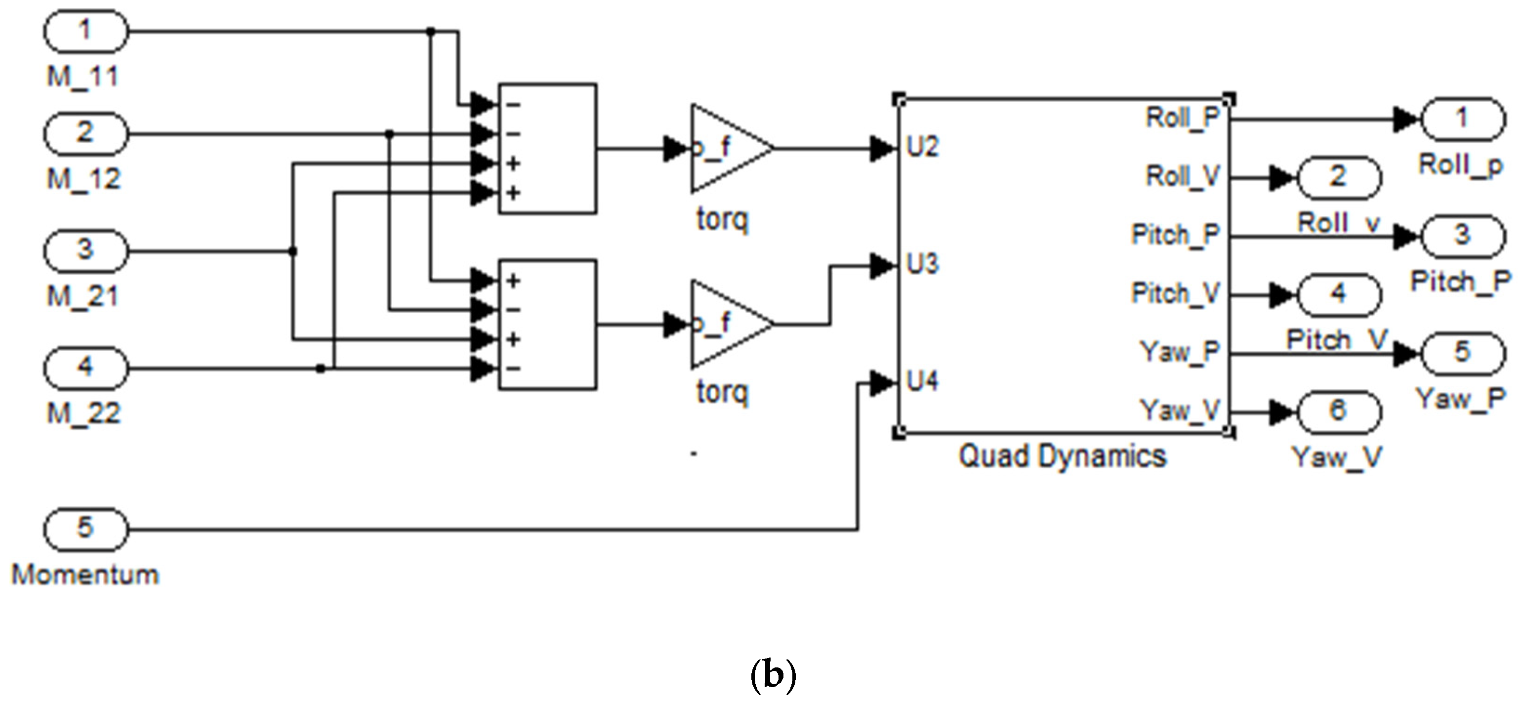
Before hardware implementation, simulation tests were performed using the Simulink model of the quadrotor with the control structure implemented on a microcontroller, as it is presented in Figure 7a,b. The Arduino block in Figure 7a is used to receive and send data from and to the dedicated microcontroller and also contains the control scheme and equations as detailed in Figure 4, Figure 5 and Figure 6.
The values of the angular velocities are measured by gyroscopes, and no additional data filtration or processing was needed. To estimate the angular positions, a classical Kalman filter was used, which receives the data from the gyroscopes and reads data from the accelerometer. The filter was used to obtain a smooth measurement of the angular position by minimizing the standard deviation error between the estimated model and real measurements (from accelerometer and gyroscope). The White Gaussian noise was rejected [25].
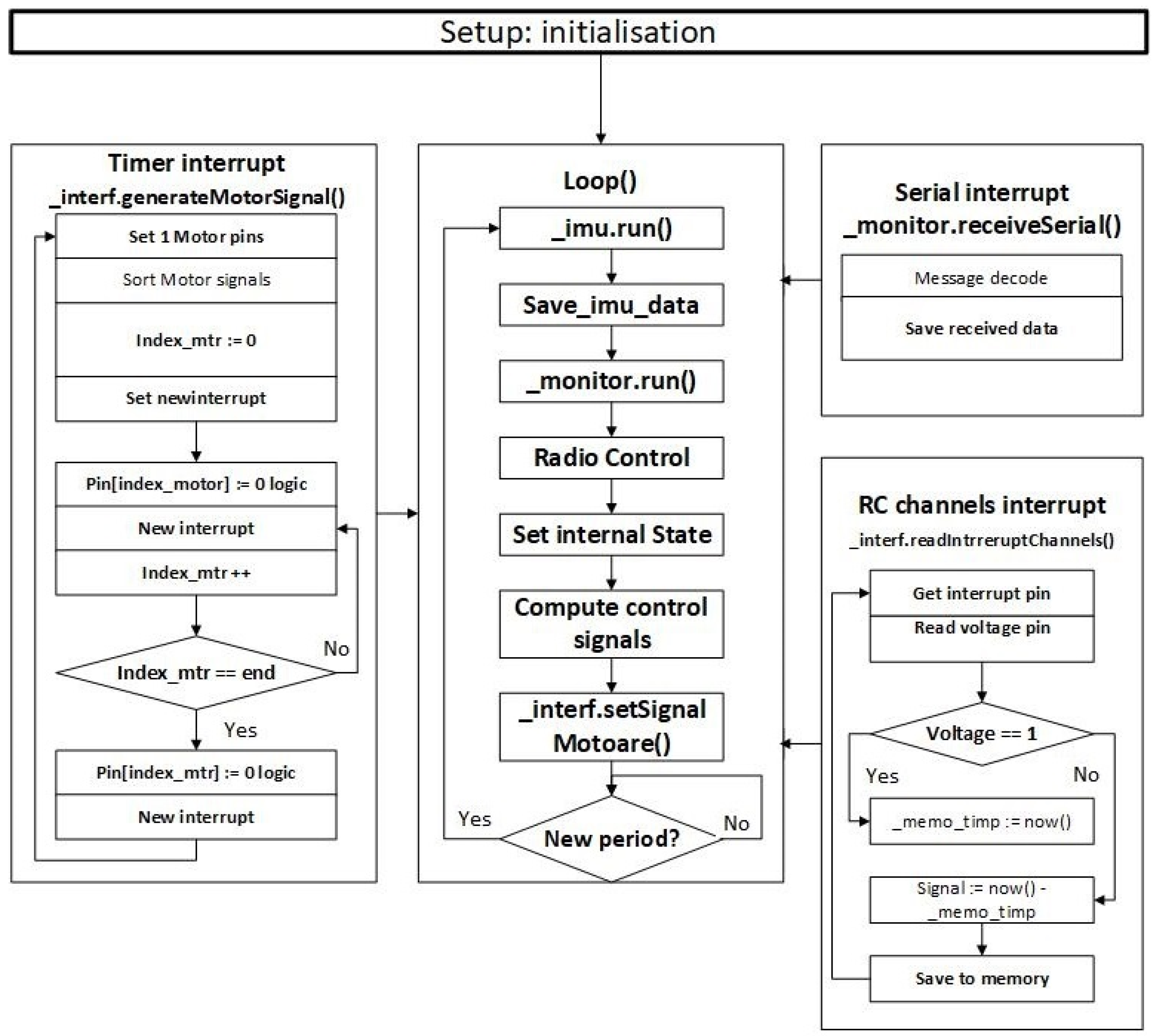
A new C++ library was designed in order to implement the functionality of this regulator on a micro-controller. The implemented execution structure is presented in Figure 8. The whole control algorithm was organized into three important parts: the algorithm, the interrupt system, and the communication unit. The main one, the loop, implemented the algorithm itself where the inertial sensors are red and when processed by the Kalman filter and saved, the operator setpoints are red. Based on these data, the output signals are calculated. This main program was executed at a fixed period, which in this case was 4 milliseconds. Furthermore, a monitor function evaluated the internal status of the program and takes action if an execution error appears, for example, by resetting the microcontroller if the executions thread has stuck.
The interrupt system was used to calculate the desired control values of each motor. The calculated control signals were generated using a variable timer interrupt. Based on the values calculated by the proposed control strategy, a timer interrupted the main thread in order to change the state of the output pin of the desired motor. The interrupt period of the timer was actualized continuously with the time value of the next desired output, which was then generated. Thus, the execution was parallelized, and the main loop did not wait until each output is generated.
The operator setpoints could be given through a serial port communication or by using a radio receiver. In both cases, the interrupt system is used to decode the received message. The values returned after the decoding process were saved and used by the main execution thread.
In the second stage, each controller was changed with a FO-PID controller. As mentioned in the introductory section, the fractional-order PID controller was preferred over the integer-order ones due to its now well-recognized superiority [26]. The transfer function of such a controller is:
where are the fractional orders and kp, kd and ki are standard PID gains. In the case of , a classical integer-order PID controller is resulting.
To tune the FO-PIDs, a set of performance criteria that refer to the open-loop gain crossover frequency (ωgc), phase margin (φm) and iso-damping property was imposed as follows [18]:
where HP(s) denotes the process model for an axis and Hd(s) is the open-loop transfer function. During the tuning process of the fractional-order controllers, a linearized model of (1)–(3) was derived for each input–output pairing according to Equations (4) and (5).
A cost function was later defined as follows:
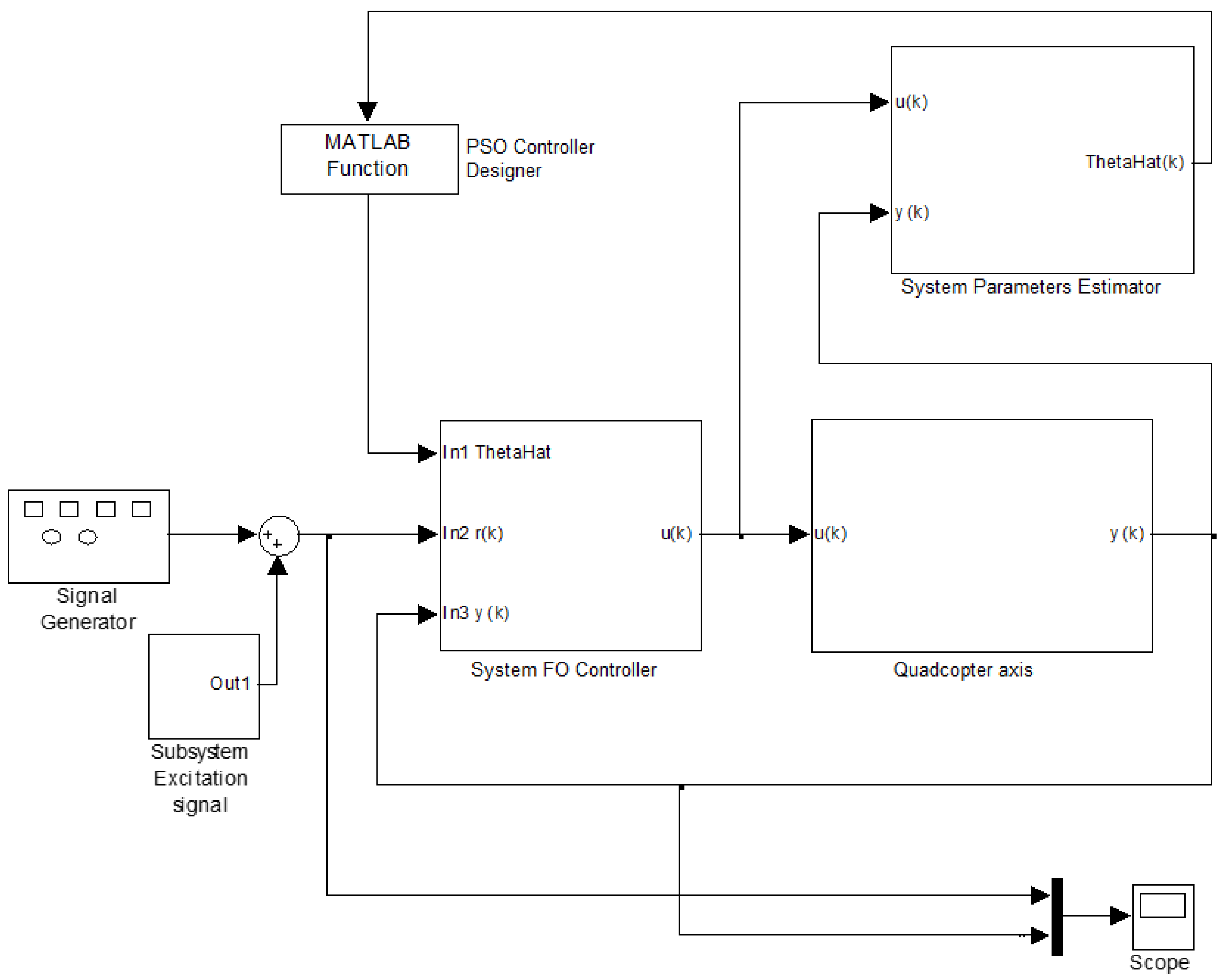
with the vector of FO-PID controller parameters and the system of nonlinear Equations (8)–(10). Additional functions could be added in (11) to include a set of constraints to the systems, such as control effort minimization. Using a modified Particle Swarm Optimization (PSO), FO-PID parameters were determined by minimizing the cost function (11). This algorithm is based on an approach created by Eberhart and Kennedy [27]. The following Simulink/MATLAB® diagram, presented in Figure 9, implemented the adaptive fractional order PID controller for a single axis. The “Quadcopter axis” block was used to simulate one axis behavior of the quadrotor; the “Subsystem Parameters Estimator” calculated the process parameters using a GPC algorithm [24]. The system parameters are used by the “PSO Controller Designer” block to determine the controller parameters using the PSO algorithm. The “Subsystem FO Controller” was the implemented FO-PID controller.
The PSO algorithm described above was implemented in MATLAB® to tune the FO-PID parameters. An initial population of 500 particles was randomly initialized. The algorithm changes each particle or vector value in order to minimize the fitness function (11). The tuning script was kept running until the fitness function was equal to 0 or until 1000 iterations are reached. Each particle in the swarm was evaluated and its value changed according to its personal best position and the entire group’s best position.
3. Results
Comparing the performances gained by applying an adaptive PID controller and an adaptive FO-PID controller on the same experimental quadrotor prototype, a series of advantages can be highlighted for the proposed control strategy. Since the classical PID controller has three tuning parameters (proportional, integral and derivative gains), three performance specifications were imposed: a gain crossover frequency = 20 rad/sec, a phase margin φm = 100° and robustness to gain variations (iso-damping). The PID controller parameters are determined based on the three tuning Equations in (8)–(10) and the minimization of the corresponding cost function (11). The design specifications were chosen to increase the overall system stability (greater phase margin) and to ensure a fast settling time (greater gain crossover frequency). For the fractional-order controller, having two more degrees of freedom also includes the robustness condition (10). The resulted PID controller has the parameters: kp = 4.65; ki = 2.2; kd = 0.15. An anti-saturation gain has also been designed as Kt = 3.83 and used for each loop in the process.
The fractional-order PID controller in (7) has five tuning parameters. Thus, two supplementary degrees of freedom. To tune this controller, the same performance specifications were imposed as in the design of the integer-order PID controller. Since the FOPID has extra degrees of freedom, a constraint regarding the minimization of the control effort was added as a design specification. The tuning of the FOPID was based on the minimization of the cost function (11) and the results are as follows: kp = 5.0501; ki = 0.2758; kd = 0.0097 and the derivative order is 0.5085, while the integrative order is 0.6747. To implement the controller, the Oustaloup Recursive Approximation method is used [28] within the frequency band [1, 10] rad/s and with an order of N = 10. Each controller was implemented as a recursive equation obtained from the discrete-time form of the controllers. The sampling period is 0.004 sec, this being the minimum time required to execute the control algorithm on the microcontroller.
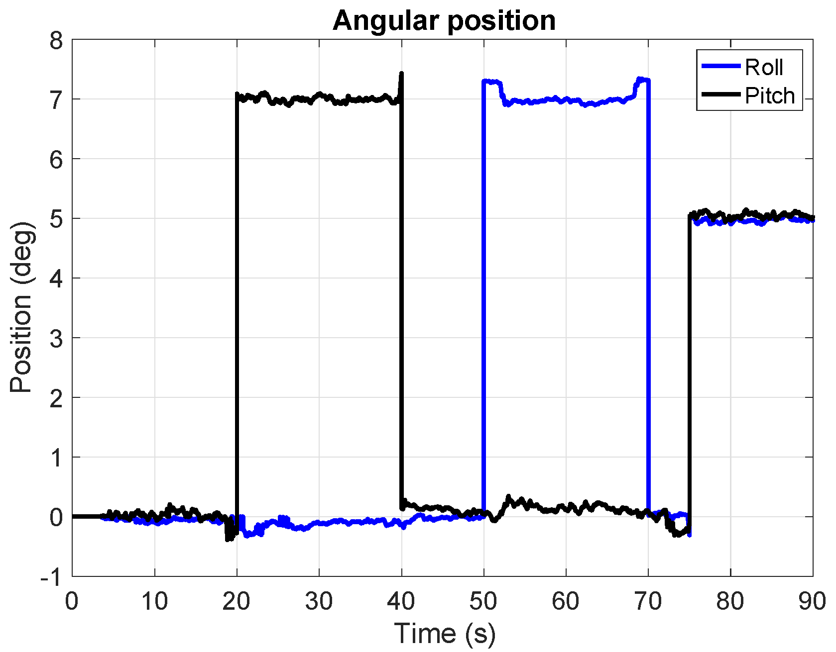
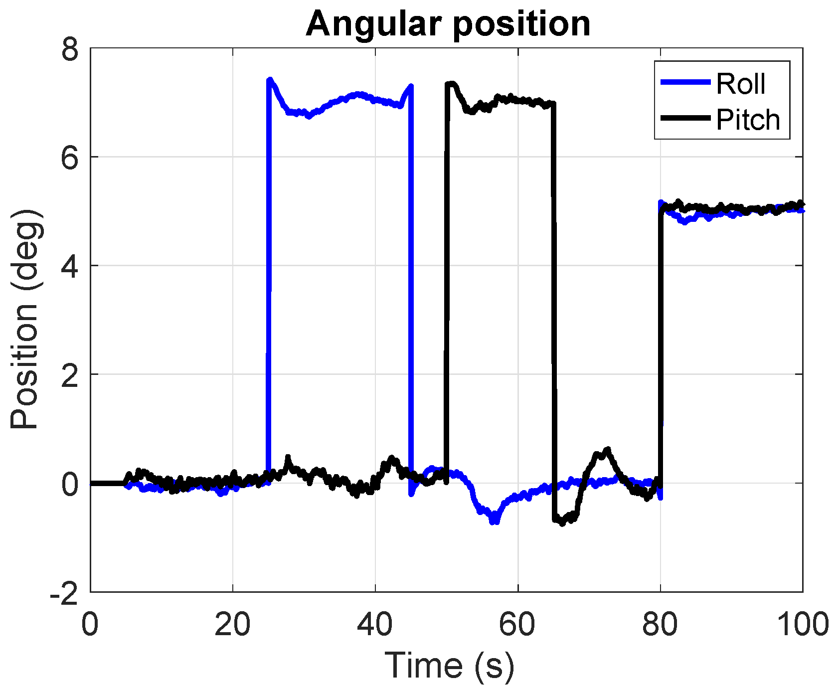
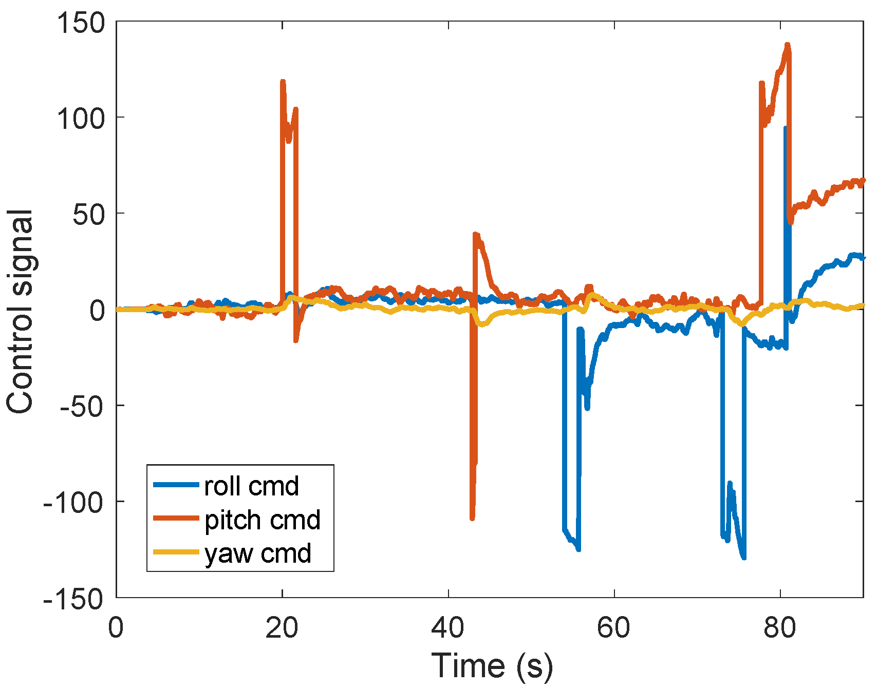
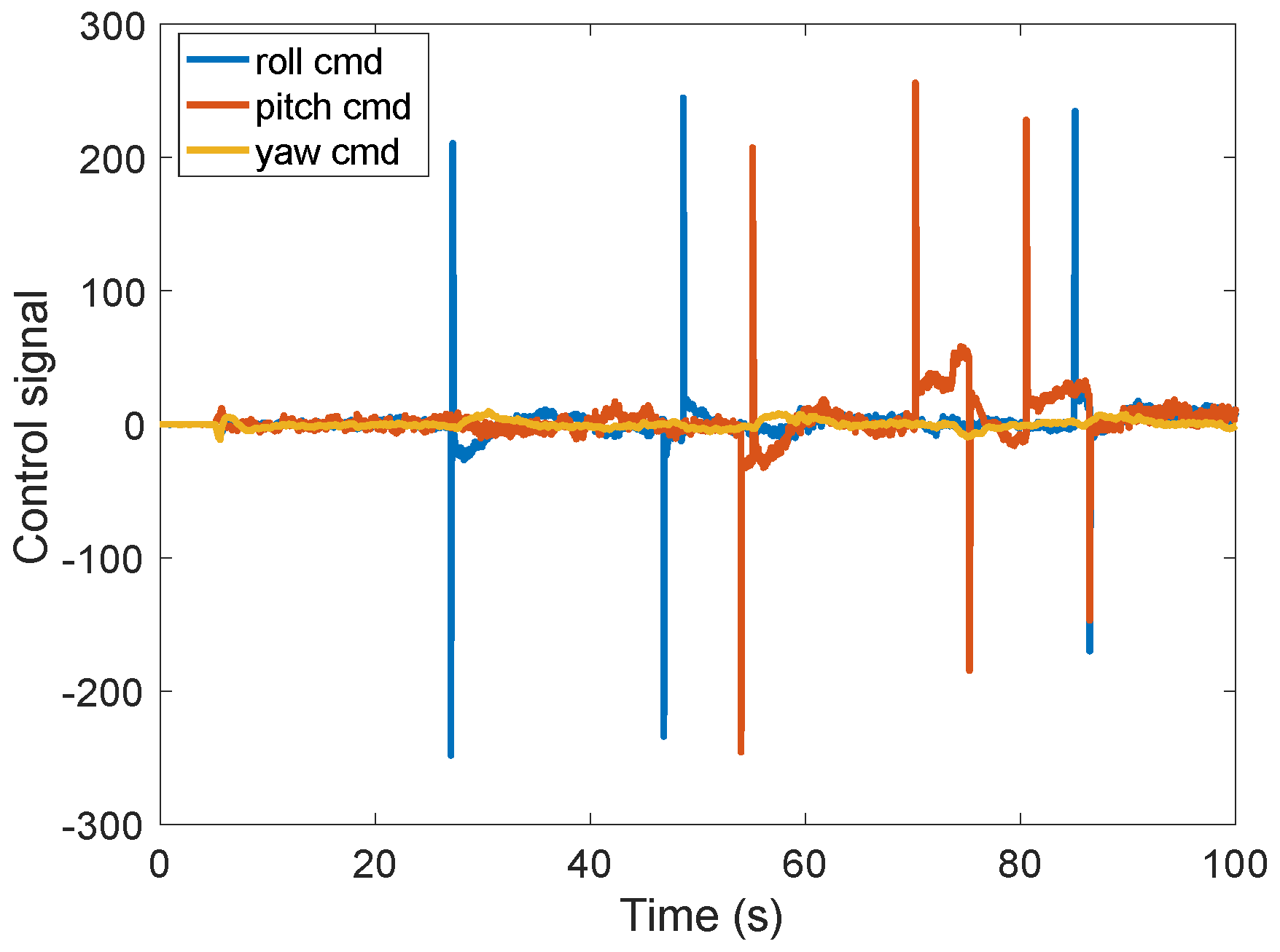
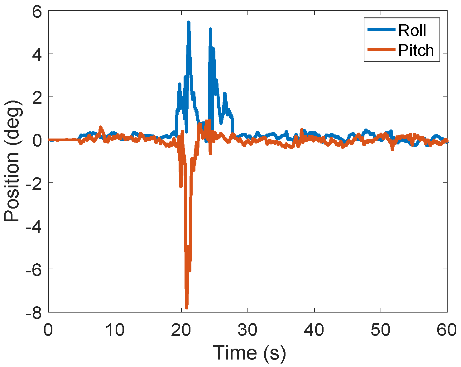
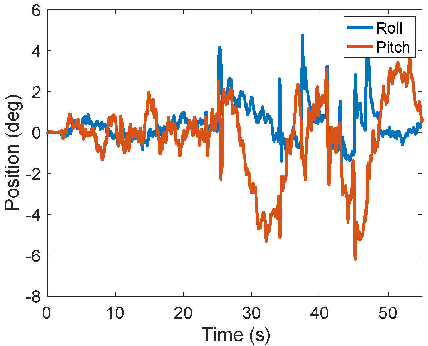
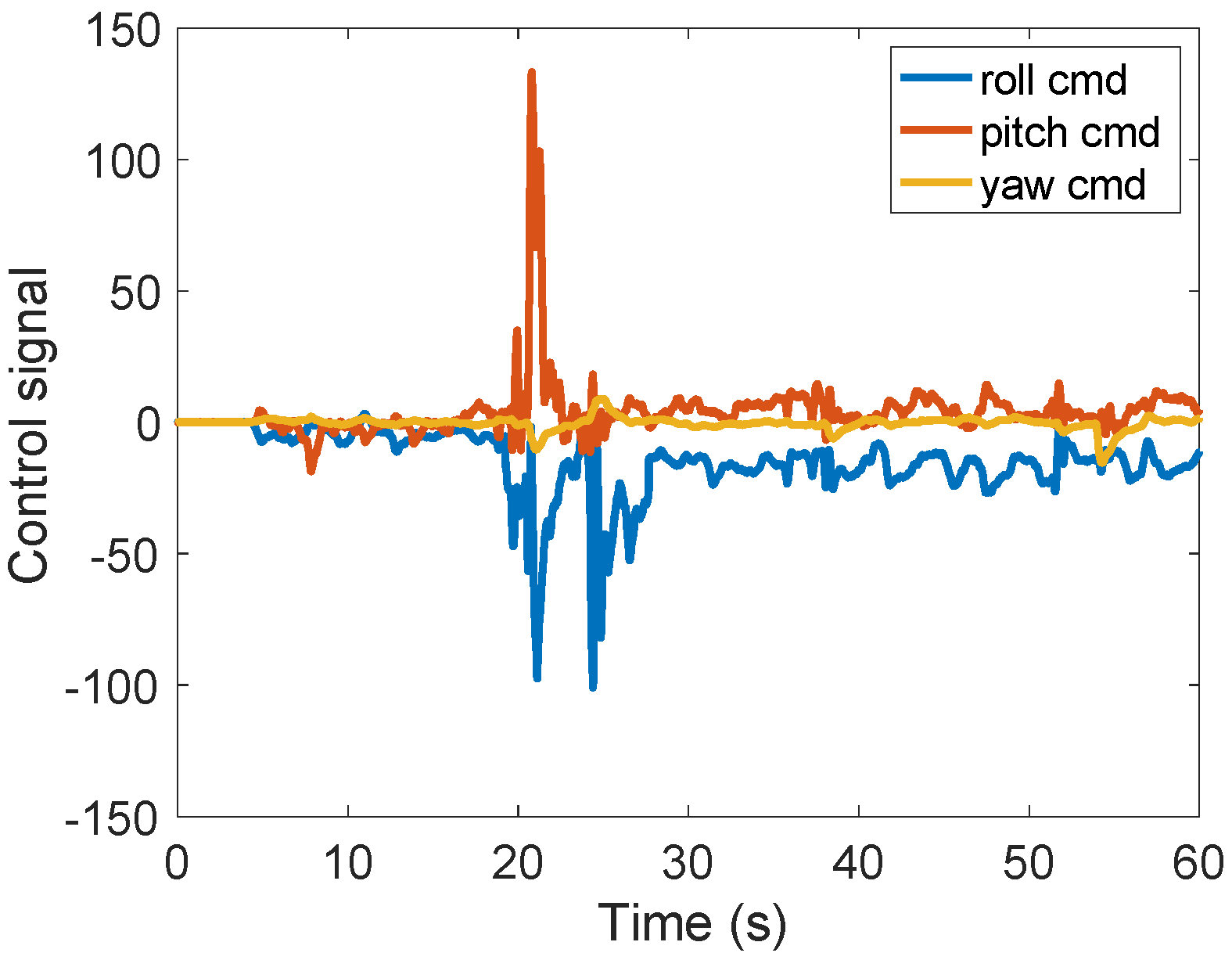
The experimental results obtained on the physical model, with the adaptive integer-order and fractional-order PID controllers, are indicated in Figure 10 and Figure 11. These results aim to demonstrate how the quadrotor system is responding to a certain setpoint applied on a pitch and roll axis and how they affect each other. The setpoints in both cases were 7 degrees. The results clearly showed that both control strategies are able to ensure reference tracking, although the integer-order controllers exhibit some large oscillations due to the loop interactions. The corresponding control signals are indicated in Figure 12 and Figure 13. The control signals represent a differential PWM factor for each pair of motors in order to generate the desired torque to the body frame. This factor determines how faster a pair of motors should spin, and that is determined by how many extra microseconds that specific motor should be set on a 5-volt command signal. For example, in Figure 12, at 20 s, the pair of motors m11 and m21 should be set on 5 volts by the microcontroller with approximately 100 extra milliseconds compared with motors m12 and m22. These are non-dimensional values. In Figure 12, the command effort is less than in Figure 13 and no fast control oscillation was detected, which can cause instability in the process.
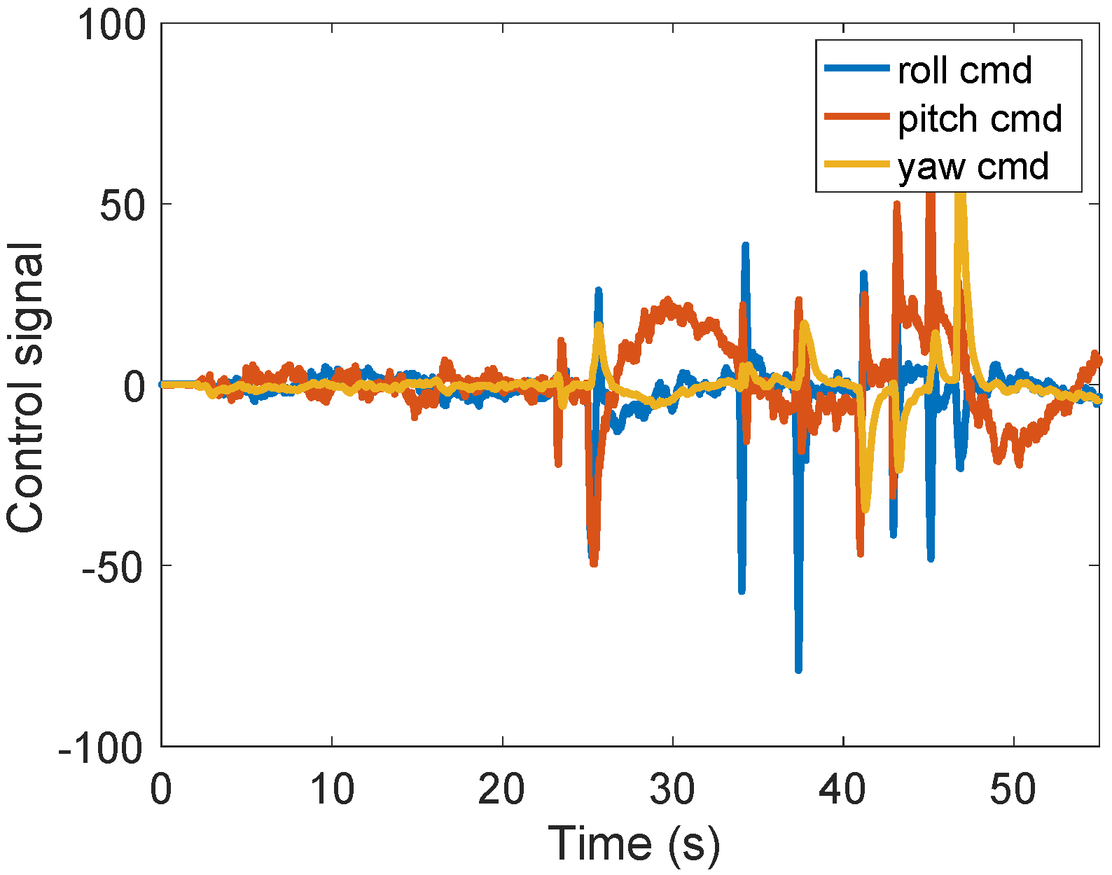
For the disturbance rejection case, Figure 14 and Figure 15 depict the closed-loop experimental results regarding the roll and pitch position, whereas Figure 16 and Figure 17 present the corresponding input signals. During flight, the system could be disturbed by unexpected wind or air pressure changes. These disturbance experiments aim to validate the control system’s fast response to these types of changes. It was obvious that the adaptive fractional-order controllers outperformed the adaptive integer-order PIDs and efficiently rejected disturbances by quickly returning to equilibrium. In the case of the adaptive PID controller, even small disturbances caused the quadcopter to oscillate, although the designed control strategy maintained the stability of the overall system.
4. Conclusions
This research presents a comparative study between a classical PID controller and a fractional-order PID controller applied on a physical prototype of a quadrotor system. These two control methods were integrated within an adaptive structure and implemented on a microcontroller. The favorable results of the proposed control structure obtained on the real process represent the novelty of this research. The tuning of the fractional-order controllers is based on ensuring stability, a fast response, its iso-damping property, as well as the minimization of the control effort. The effects of disturbances acting on the pitch, roll or yaw motions are eliminated by setting the adaptive control strategy. In addition, the strategic advantages are highlighted by using an adaptive fractional-order controller. The experimental results considering both reference tracking, as well as disturbance rejection, clearly demonstrate the efficiency of the adaptive fractional-order controllers compared to their integer-order counterparts. Interaxial dependency effects have a limited impact on the fractional structure compared with that of the classical. This behavior could affect the whole stability of the system over time. Furthermore, the command effort is smaller in the case of the fractional structure with no oscillation, which improves its overall performance. Further research includes testing different fractional-order control strategies and their applications to unmanned aerial vehicles. Flight planning and image processing features will be added in order to develop a surveillance application.
Author Contributions
Conceptualization, D.D.T., E.-H.D. and C.I.M.; methodology D.D.T. and E.-H.D.; software, D.D.T.; validation C.I.M.; writing—original draft preparation, E.-H.D. All authors have read and agreed to the published version of the manuscript.
Funding
This research was funded by a grant from the Romanian National Authority for Scientific Research and Innovation, CNCS/CCCDI-UEFISCDI, project number PN-III-P1-1.1-TE-2019-0745.
Institutional Review Board Statement
Not applicable.
Informed Consent Statement
Not applicable.
Data Availability Statement
The data presented in this study are available within the manuscript.
Conflicts of Interest
The authors declare no conflict of interest.
References
- Altan, A.; Hacioğlu, R. Model predictive control of three-axis gimbal system mounted on UAV for real-time target tracking under external disturbances. Mech. Syst. Signal Process. 2020, 138, 106548. [Google Scholar] [CrossRef]
- Wang, B.; Yu, X.; Mu, L.; Zhang, Y. Disturbance observer-based adaptive fault-tolerant control for a quadrotor helicopter subject to parametric uncertainties and external disturbances. Mech. Syst. Signal Process. 2018, 120, 727–743. [Google Scholar] [CrossRef]
- Becerra, V.M. Autonomous Control of Unmanned Aerial Vehicles. Electronics 2019, 8, 452. [Google Scholar] [CrossRef] [Green Version]
- Jatsun, S.; Emelyanova, O.; Leon, A.S.M. Design of an Experimental Test Bench for a UAV Type Convertiplane. IOP Conf. Ser. Mater. Sci. Eng. 2020, 714, 012009. [Google Scholar] [CrossRef]
- Dulf, E.H.; Saila, M.; Muresan, C.I.; Miclea, L.C. An Efficient Design and Implementation of a Quadrotor Unmanned Aerial Vehicle Using Quaternion-Based Estimator. Mathematics 2020, 8, 1829. [Google Scholar] [CrossRef]
- Cajo, R.; Mac, T.T.; Plaza, D.; Copot, C.; De Keyser, R.; Ionescu, C. A Survey on Fractional Order Control Techniques for Unmanned Aerial and Ground Vehicles. IEEE Access 2019, 7, 66864–66878. [Google Scholar] [CrossRef]
- Efe, M. Battery power loss compensated fractional order sliding mode control of a quadrotor UAV. Asian J. Control 2011, 14, 413–425. [Google Scholar] [CrossRef]
- Feng, G.; Xiao-Ping, Z. Research on fractional order two-degrees-of-freedom flight control technology of unmanned air vehicle. In Proceedings of the 2012 International Conference on Computer Science and Information Processing (CSIP), Xi’an, China, 24–26 August 2012; pp. 807–812. [Google Scholar]
- Chao, H.; Luo, Y.; Di, L.; Chen, Y.Q. Roll-channel fractional order controller design for a small fixed-wing unmanned aerial vehicle. Control Eng. Pract. 2010, 18, 761–772. [Google Scholar] [CrossRef]
- Luo, Y.; Chen, Y.; Di, L.; Chao, H. Lateral directional fractional order (PI)α control of a small fixed-wing unmanned aerial vehicles: Controller designs and flight tests. IET Control Theory Appl. 2011, 5, 2156–2167. [Google Scholar] [CrossRef]
- Han, J.; Di, L.; Coopmans, C.; Chen, Y. Pitch Loop Control of a VTOL UAV Using Fractional Order Controller. J. Intell. Robot. Syst. 2013, 73, 187–195. [Google Scholar] [CrossRef]
- Vahdanipour, M.; Khodabandeh, M. Adaptive fractional order sliding mode control for a quadrotor with a varying load. Aerosp. Sci. Technol. 2019, 86, 737–747. [Google Scholar] [CrossRef]
- Souza, A.G.; Souza, L. Design of a controller for a rigid-flexible satellite using the H-infinity method considering the parametric uncertainty. Mech. Syst. Signal Process. 2018, 116, 641–650. [Google Scholar] [CrossRef]
- Noormohammadi-Asl, A.; Esrafilian, O.; Arzati, M.A.; Taghirad, H.D. System identification and H∞-based control of quadrotor attitude. Mech. Syst. Signal Process. 2019, 135, 106358. [Google Scholar] [CrossRef]
- Muresan, C.I.; Birs, I.; Ionescu, C.; Dulf, E.H.; De Keyser, R. A Review of Recent Developments in Autotuning Methods for Fractional-Order Controllers. Fractal Fract. 2022, 6, 37. [Google Scholar] [CrossRef]
- Dulf, E.-H. Simplified Fractional Order Controller Design Algorithm. Mathematics 2019, 7, 1166. [Google Scholar] [CrossRef] [Green Version]
- Dulf, E.H.; Timis, D.D.; Muresan, C.I. Robust Fractional Order Controllers for Distributed Systems. Acta Polytehnica Hung. 2017, 14, 163–176. [Google Scholar]
- Muresan, C.I.; Birs, I.R.; Dulf, E.H. Event-Based Implementation of Fractional Order IMC Controllers for Simple FOPDT Processes. Mathematics 2020, 8, 1378. [Google Scholar] [CrossRef]
- Huang, C.; Li, H.; Cao, J. A novel strategy of bifurcation control for a delayed fractional predator–prey model. Appl. Math. Comput. 2018, 347, 808–838. [Google Scholar] [CrossRef]
- Huang, C.; Wang, J.; Chen, X.; Cao, J. Bifurcations in a fractional-order BAM neural network with four different delays. Neural Networks 2021, 141, 344–354. [Google Scholar] [CrossRef]
- Dulf, E.; Muresan, C.I.; Timis, D.D. Adaptive Fractional Order Control of a Quadrotor. In Proceedings of the 15th International Conference on Dyanmical Systems Theory and Applications (DSTA 2019), Lodz, Poland, 2–5 December 2019. [Google Scholar]
- Laporte-Fauret, Q.; Marieu, V.; Castelle, B.; Michalet, R.; Bujan, S.; Rosebery, D. Low-Cost UAV for high-resolution and large-scale coastal dune change monitoring using photogrammetry. J. Mar. Sci. Eng. 2019, 7, 63. [Google Scholar] [CrossRef] [Green Version]
- Balas, C. Modelling and Linear Control of a Quadrotor. Master’s Thesis, Cranfield University, Cranfield, UK, 2007. Available online: https://citeseerx.ist.psu.edu/viewdoc/download?doi=10.1.1.96.8228&rep=rep1&type=pdf (accessed on 19 March 2022).
- Ai, L.; Xu, Y.; Deng, L.; Teo, K. Least Squares Support Vector Machine-Based Multivariate Generalized Predictive Control for Parabolic Distributed Parameter Systems with Control Constraints. Symmetry 2021, 13, 453. [Google Scholar] [CrossRef]
- Kaba, A.; Ermeydan, A.; Kiyak, E. Model Derivation, Attitude Control and Kalman Filter Estimation of a Quadcopter. In Proceedings of the 2017 4th International Conference on Electrical and Electronic Engineering (ICEEE), Ankara, Turkey, 8–10 April 2017; pp. 210–214. [Google Scholar]
- Podlubny, I. Fractional-Order Systems and PIλDμ–Controllers. IEEE Trans. Autom. Control 1999, 44, 208–213. [Google Scholar] [CrossRef]
- Eberhart, R.; Kennedy, J. A New Optimizer Using Particle Swarm Theory. In Proceedings of the 6th International Symposium Micro Machine and Human Science (MHS), Nagoya, Japan, 4–6 October 1995; pp. 39–43. [Google Scholar]
- Oustaloup, A.; Levron, F.; Mathieu, B.; Nanot, F.M. Frequency-band complex noninteger differentiator: Characterization and synthesis. IEEE Trans. Circuits Syst. I 2000, 47, 25–39. [Google Scholar] [CrossRef]
Figure 1.
The quadrotor blueprints.

Figure 2.
The quadrotor on the testing bench.

Figure 3.
The movement of the quadrotor. (a) Quadcopter movements. (b) Quadcopter angular positions are generated by differential torque.
Figure 3.
The movement of the quadrotor. (a) Quadcopter movements. (b) Quadcopter angular positions are generated by differential torque.

Figure 4.
The adaptive control structure.

Figure 5.
The proposed cascade control loop for an axis.

Figure 6.
The proposed PID structure.

Figure 7.
(a) Simulink implementation of the closed-loop system. (b) Simulink implementation of the quadrotor dynamics.
Figure 7.
(a) Simulink implementation of the closed-loop system. (b) Simulink implementation of the quadrotor dynamics.


Figure 8.
The execution structure of the controller software.

Figure 9.
Simulink/MATLAB® diagram implementing the adaptive control structure with the fractional-order controller.
Figure 9.
Simulink/MATLAB® diagram implementing the adaptive control structure with the fractional-order controller.

Figure 10.
Closed-loop experimental results with the adaptive fractional-order PID controllers.

Figure 11.
Closed-loop experimental results with the adaptive integer-order PID controllers.

Figure 12.
Control signals in the adaptive fractional-order PID control strategy.

Figure 13.
Control signals in the adaptive integer-order PID control strategy.

Figure 14.
Disturbance rejection experimental results with the adaptive fractional-order PID controllers.
Figure 14.
Disturbance rejection experimental results with the adaptive fractional-order PID controllers.

Figure 15.
Disturbance rejection experimental results with the adaptive integer-order PID controllers.
Figure 15.
Disturbance rejection experimental results with the adaptive integer-order PID controllers.

Figure 16.
Control signals in the adaptive fractional-order PID control strategy for disturbance rejection.
Figure 16.
Control signals in the adaptive fractional-order PID control strategy for disturbance rejection.

Figure 17.
Control signals in the adaptive integer-order PID control strategy for disturbance rejection.
Figure 17.
Control signals in the adaptive integer-order PID control strategy for disturbance rejection.

Publisher’s Note: MDPI stays neutral with regard to jurisdictional claims in published maps and institutional affiliations. |
© 2022 by the authors. Licensee MDPI, Basel, Switzerland. This article is an open access article distributed under the terms and conditions of the Creative Commons Attribution (CC BY) license (https://creativecommons.org/licenses/by/4.0/).
Share and Cite
MDPI and ACS Style
Timis, D.D.; Muresan, C.I.; Dulf, E.-H. Design and Experimental Results of an Adaptive Fractional-Order Controller for a Quadrotor. Fractal Fract. 2022, 6, 204. https://0-doi-org.brum.beds.ac.uk/10.3390/fractalfract6040204
AMA Style
Timis DD, Muresan CI, Dulf E-H. Design and Experimental Results of an Adaptive Fractional-Order Controller for a Quadrotor. Fractal and Fractional. 2022; 6(4):204. https://0-doi-org.brum.beds.ac.uk/10.3390/fractalfract6040204
Chicago/Turabian StyleTimis, Daniel D., Cristina I. Muresan, and Eva-H. Dulf. 2022. "Design and Experimental Results of an Adaptive Fractional-Order Controller for a Quadrotor" Fractal and Fractional 6, no. 4: 204. https://0-doi-org.brum.beds.ac.uk/10.3390/fractalfract6040204