
Hybrid LoRa-IEEE 802.11s Opportunistic Mesh Networking for Flexible UAV Swarming


Internet of Things (IoT) Laboratory, Department of Engineering and Architecture, University of Parma, 43124 Parma, Italy
*
Author to whom correspondence should be addressed.
Drones 2021, 5(2), 26; https://0-doi-org.brum.beds.ac.uk/10.3390/drones5020026
Submission received: 11 March 2021
/
Revised: 8 April 2021
/
Accepted: 12 April 2021
/
Published: 15 April 2021
(This article belongs to the Special Issue Mobile Fog and Edge Computing in Drone Swarms)
Abstract
:Unmanned Aerial Vehicles (UAVs) and small drones are nowadays being widely used in heterogeneous use cases: aerial photography, precise agriculture, inspections, environmental data collection, search-and-rescue operations, surveillance applications, and more. When designing UAV swarm-based applications, a key “ingredient” to make them effective is the communication system (possible involving multiple protocols) shared by flying drones and terrestrial base stations. When compared to ground communication systems for swarms of terrestrial vehicles, one of the main advantages of UAV-based communications is the presence of direct Line-of-Sight (LOS) links between flying UAVs operating at an altitude of tens of meters, often ensuring direct visibility among themselves and even with some ground Base Transceiver Stations (BTSs). Therefore, the adoption of proper networking strategies for UAV swarms allows users to exchange data at distances (significantly) longer than in ground applications. In this paper, we propose a hybrid communication architecture for UAV swarms, leveraging heterogeneous radio mesh networking based on long-range communication protocols—such as LoRa and LoRaWAN—and IEEE 802.11s protocols. We then discuss its strengths, constraints, viable implementation, and relevant reference use cases.
1. Introduction
The diffusion and wide adoption of Unmanned Aerial Vehicles (UAVs) has grown in a significant way in the last years due to the availability of inexpensive and “smarter” Commercial-Off-The-Shelf (COTS) products by both world-leading UAV manufacturers (e.g., DJI [1]) and other small companies, which develop ad hoc solutions for specific scenarios. In the last five years, the price of a Ready-to-Fly (RTF) solution equipped with (i) a Global Navigation Satellite System (GNSS), (ii) a 4K resolution camera fixed on a gimbal (namely, a device for keeping an instrument stable and aligned with horizon, typically consisting of rings pivoted at right angles), (iii) on-board advanced sensing elements (e.g., obstacle detection and anti-collision systems), and (iv) a reliable communication system between the UAV and the terrestrial pilot (able to provide a real-time high-quality video stream) reduced from more than 1000 USD (e.g., in 2015, the DJI Phantom 3 Pro UAV [2] had an initial price of 1259 USD) to 400–500 USD (e.g., the new DJI Mini 2 [3] released in 2020 had a price of 449 USD). Moreover, this cost reduction boosted an impressive market growth of the commercial drones sector, further enhanced by the current COVID-19 pandemic situation, in which the adoption of UAVs for remote monitoring and enhanced services provisioning exponentially increased [4]. While the commercial use of UAVs for aerial photography and remote monitoring can rely on consolidated and reliable solutions (e.g., wireless communication systems among the drone and the pilot for Visual Line-of-Sight (VLOS) operations), there are still several technical difficulties to overcome when dealing with long-range UAV swarm applications, namely Beyond VLOS (BVLOS) operations, where a multitude of UAVs may simultaneously be flying over a wide area and must be connected to each other in order to coordinate and perform complex operations.
Focusing on these heterogeneous scenarios, in this paper, we propose a hybrid opportunistic mesh networking approach based on Long Range (LoRa) [5] and IEEE 802.11s [6] protocols for flying UAV swarms, involving both UAV-to-UAV and UAV-to-ground communications. This architecture allows multiple flying drones to exchange essential data—e.g., telemetry information—with each other or toward one or more ground control centers, thus opening new possibilities for UAV-based applications over wide operational areas. Long Range Wide Area Network (LoRaWAN [7] at a Medium Access Control (MAC) layer) as well as LoRa (at the physical (PHY) layer) are attractive as they allow users to reach long distances (on the order of several kilometers) in Line-of-Sight (LOS) applications [8,9], e.g., inside the swarm. On the other end, IEEE 802.11 (Wi-Fi) [10] is widely adopted in a multitude of applications and is often used for UAV-to-pilot real-time video broadcasting, given its direct visibility-operating distance ranging from a few hundreds of meters up to one or more kilometers. Nevertheless, in a complete LOS environment (such as that between flying UAVs), the selection of an appropriate Wi-Fi implementation can allow for high bandwidth data stream between multiple nearby UAVs, thus opening additional possibilities given its proper features. Therefore, the use of IEEE 802.11s, which builds upon IEEE 802.11, is very attractive.
In order to exploit the strengths of two communication protocols of interest and to limit the impact of their constraints in the adoption of UAV swarms, a “meshification” of LoRa- and IEEE 802.11s-based communication patterns (through opportunistic switching, handling, and management mechanisms) may allow us to cover several use cases based on the use of UAV swarms as well as to provide a good tradeoff between operational range and available bandwidth. Then, combining different heterogeneous wireless communication networks—namely, a LoRa-based communication layer for long distances and constrained payload communications, and an IEEE 802.11s-based communication layer for mid-range and unconstrained payload applications—will allow them to coexist. Hence, being on two separate layers, a smart switching mechanism must be defined to choose the most suitable network to be used in a certain time instant, also based on the task’s requirements and network quality conditions (e.g., based on Received Signal Strength Index (RSSI) and localization of flying neighbor UAVs or ground control stations). Therefore, the proposed switching mechanism takes into account the capabilities and constraints of each available communication protocol in terms of both operational range and admitted payload, optimizing the performances in the considered application scenarios.
In order to avoid confusion, we preliminarily comment on how the term UAV will be used in the remainder of this paper. In general terms, UAV is used to indicate various types of remotely or autonomously piloted aerial vehicles, ranging from small quad-copters—also denoted as drones and with a weight from hundreds of grams up to tens of kilograms—to large-size aerial vehicles involved in military operations—with a weight up to thousands of kilograms. In the following, the term UAV will refer to commonly and widely adopted commercial drones having a Maximum TakeOff Weight (MTOW) of 25 kg and flying at a maximum Above Ground Level (AGL) of 120 m, given the aerospace regulation rules applied in both Europe (by the European Union Aviation Safety Agency (EASA) [11]) and the US (by the Federal Aviation Administration (FAA) [12]).
The remainder of this paper is organized as follows. In Section 2, a literature overview on UAV-oriented communication solutions and relevant research projects is presented, analyzing their advantages and disadvantages. In Section 3, the communication protocols adopted in the proposed hybrid architecture are detailed and analyzed, discussing their strengths and limitations. Section 4 presents the proposed hybrid LoRa-IEEE 802.11s opportunistic mesh networking approach, while in Section 5, the opportunistic network interfaces switching mechanism is discussed. In Section 6, the theoretical and experimental performance results are shown, while Section 7 discusses a few relevant use cases and scenarios. Finally, in Section 8, we draw our conclusions and possible improvements for the proposed system architecture.
2. State-of-the-Art
Commercial UAVs actually use different wireless communication protocols to transmit or receive essential data—e.g., a real-time First Point of View (FPV) video stream from the drone—in order to provide an advanced flying experience to the pilot. Other data transmitted wirelessly include drone’s telemetry data and video streams (downlink) and, of course, the drone’s input commands sent from the Radio Controller (RC) handled by the pilot (uplink).
Nowadays, modern commercial solutions often adopt the Wi-Fi protocol (in the 2.4 GHz and 5.8 GHz frequency bands) as the communication protocol between the UAV and the RC, thus providing a bidirectional communication channel sufficiently reliable to allow the pilot to fly in an obstacle-free environment for hundreds of meters. To this end, it is possible that advanced UAVs use proprietary communication protocols or Wi-Fi broadcast-based enhanced protocols, such as OcuSync [13] and LightBridge [14] transmission protocols (both defined by DJI), able to guarantee a LOS operational range of several kilometers. Instead, some high-end products are already working on Long-Term Evolution (LTE) cellular networks for high-definition real-time FPV video feeds, while telemetry and RC data are exchanged using different protocols (depending on the transmitter and receiver manufacturer [15]) based on different signal modulations (e.g., Spektrum [16], FrSky ACCST [17], and Futaba [18]) but typically working on well-known carrier frequencies—i.e., 2.4 GHz or other free Industrial, Scientific and Medical (ISM) bands (e.g., 868 MHz in Europe). Unfortunately, most of these solutions are suitable only for UAV-to-pilot mono-directional communications (with bidirectionality applying only to a limited number of protocols), with different data sent depending the type of communication protocol and considered applications.
Considering flying communications between UAVs, nowadays, they could rely on (i) Wi-Fi-oriented protocols (at different carrier frequencies) for LOS short/mid-range communication links; (ii) long-range protocols (e.g., LoRa) for communications over a large area, still with LOS communication links; and (iii) cellular networks for Non-LOS (NLOS) link-based applications, where a third-party cellular network is needed to establish a communication between multiple flying UAVs.
Several studies have shown the possible adoption of LoRa-based protocols (e.g., LoRaWAN) for UAV communications, with different long-range applications, implementations, and use cases. A preliminary use of LoRaWAN is discussed in [19], where multiple UAVs are used as flying LoRaWAN gateways (GWs) to provide a network coverage to ground LoRaWAN-based end nodes and to exploit LoRaWAN only for ground-to-UAV applications in emergency-like situations while the backbone network relies on Wi-Fi (assuming LOS links). A similar approach is presented in [20], where multiple flying UAVs, each one equipped with a LoRaWAN GW, cooperate to form a complex LoRaWAN-oriented urban surveillance system to provide efficient and selective network coverage. However, in all the cited works, LoRa-based communications are almost always used for ground-to-UAV interactions among on-field end nodes and the LoRaWAN network (composed of both flying UAVs, acting as GWs, and ground GWs) in order to efficiently extend the coverage of the whole network for specific use cases in some operational regions. Another UAV-enabled flying LoRaWAN networking approach was discussed in [21], with a focus on disaster management applications, combining flying LoRaWAN GWs with Wi-Fi communications from a UAV-to-ground Access Point (AP) and LoRaWAN end nodes, with the goal to follow the emergency operators to collect data and positions. Even in this scenario, LoRa-based communications are used for data collection from ground end nodes, aiming at following the moving ground devices to guarantee a reliable network for emergency applications.
A different scenario with UAV-to-ground LoRaWAN communications, in particular as a secondary telemetry system, given the strength of LoRa modulation and LoRaWAN protocol implementation, is presented in [22]. In detail, the authors showed that LoRaWAN could be employed for communications among flying UAVs and the existing LoRaWAN ground network, in particular to transmit essential telemetry data (such as GNSS latitude/longitude/altitude, drone speed, and heading direction) needed to safely handle a UAV in the presence of a RC–UAV link failure. Moreover, the possible operational ranges of this implementation are shown, investigating and simulating the behavior of LoRa RF signals at different UAV speeds and distances among the UAV and the GW in an urban environment. Unfortunately, the authors of [22] do not consider the use of LoRa for multiple flying UAVs communications—to let the farthest drones using nearby flying UAVs as relays broadcast their telemetry data to the LoRaWAN ground network—thus limiting the possible use cases and effective operational ranges of the system. Another UAV-to-ground LoRaWAN-based communication application has been proposed in [23], in which the use of multiple UAVs with on-board sensors for air quality monitoring applications is discussed, further providing additional system operational results. Even in this case, LoRa-based communications are still used for UAV-to-ground communications without exploiting the potential use of flying long-range communications for some specific scenarios.
Considering the adoption of Wi-Fi in UAV swarms, in [24], an integrated solution for an autonomous flying Wireless Mesh Network (WMN), involving swarms of small UAVs, was presented. In detail, UAVs build an IEEE 802.11s-based network to let two end systems interact through intermediate airborne relays. These relays correspond to UAVs of the swarm, and all UAVs act as APs. However, this solution is not applicable to scenarios where the distance among the nodes will become larger than the maximum allowed to keep an IEEE 802.11s connection active.
The concept of Flying Ad hoc NETworks (FANETs) was discussed in [25], where additional link quality routing metrics were introduced and a network simulator-based performance analysis was discussed. Algorithmic and theoretical aspects for autonomous placement of relay nodes in a mesh network were investigated in [26]. In detail, the authors aimed to maximize the network throughput, but mainly using flying UAVs as coverage extenders for ground nodes and requiring knowledge of the three-dimensional morphological conditions of the environment. Because of this, UAVs only act as relays for data to be shared among ground stations instead of building a flying network for flying data routing. A similar approach was presented in [27], where a WMN-based mobile Cloud system for relay of intelligent information, based on Delay Tolerant Networking (DTN) and caching capabilities, was presented. However, even in this case, the mesh network was composed by ground nodes instead of flying drones.
A UAV-based emergency communication network for post-disaster management was discussed in [28], where smartphones on the ground were used as relays through an Android mobile App in turn handling UDP packets. Moreover, the authors equipped their UAVs with a Raspberry Pi (RPi) as an on-board Wi-Fi-enabled device, thus organizing the flying network not as a mesh one but as a chain of Wi-Fi nodes. In [29], the challenges of a decentralized UAV swarm deployment in resource-constrained farming environments were discussed. For similar works, the presented network does not cope with a real mesh one but requires the election of a “central” drone, in charge of performing some additional (and more complex) tasks with respect to the other UAVs composing the swarm.
In [30], a dynamic mesh network needed for data transfer among high mobility nodes (i.e., RP runs a Better Approach To Mobile Ad Hoc Network advanced, B.A.T.M.A.N. adv [31]) is presented. In detail, the authors discussed their experimental results in a range between 0 m and 60 m, with a maximum effective 1-hop range of approximately 130 m. Nevertheless, their architecture requires multiple GWs connected with a ground control center, thus remaining a ground mesh network with no aerial part. A simulated double-layer mesh network, designed and evaluated for disaster recovery scenarios, was proposed in [19], where UAVs act as GWs in a Wi-Fi ad hoc network for the traffic generated between mobile LoRaWAN nodes and a remote ground station. Similar to other works, even in this case, the only available network among the flying drones is based on the Wi-Fi protocol, thus limiting the maximum distance between flying drones. In [32], a solution for orchestrating and synchronizing a swarm of drones is proposed. In detail, their network focuses on a leader node (piloted by a human) that is followed by the remaining drones composing the swarm, on the basis of the leader’s Wi-Fi signal strength. The authors proposed operating a swarm of UAVs without relying on any existing infrastructure but only on ad hoc communications. This approach is attractive if the drones need to strictly follow their leader; at the opposite, it needs to be improved in the case when UAVs need to fly independently from each other. Moreover, in order to relay data from the point of interest to the ground control center, a certain number of intermediate UAVs (depending on the distance) will be required rather than adopting long-range communication protocols.
Finally, the application of TempoSpatial-Software Defined Networking (TS-SDN) to UAV networks, in order to extend their network coverage, was described in [33]. In order to reach this goal, a network of stratospheric balloons can be used to extend network access as well as involving ground stations and UAVs equipped with mechanically or electronically steered beams to establish highly directional links, even to nearby peers. Moreover, the authors simulate a scenario composed of more than 500 nodes to verify the behavior of different routing protocols.
3. Disjoint IEEE 802.11s and LoRa-Based Wireless Mesh Networking
As introduced in Section 1, our goal is to combine LoRa and IEEE 802.11s protocols to develop an innovative hybrid mesh architecture. For the sake of completeness, we provide an overview of IEEE 802.11s and LoRa/LoRaWAN in Section 3.1 and Section 3.2, respectively.
3.1. IEEE 802.11s Mesh Protocol
The growing interest in mesh networking in the last decade from both industrial and academic entities has led to the definition of the IEEE 802.11s protocol [6,34], an IEEE 802.11 standard amendment [10] specifically addressed to mesh networks. In particular: (i) the PHY layers of both IEEE 802.11 and IEEE 802.11s are the same; (ii) new routing procedures are introduced at the MAC layer rather than at the network layer; and (iii) in order to make routing efficient, wireless nodes must have accurate knowledge of the links connecting them to their 1-hop neighbors. In detail, an IEEE 802.11s mesh network, also denoted as Mesh Basic Service Set (MBSS), is composed of different logical components [35], as highlighted in Figure 1: (i) mesh stations (mesh STAs), participating in the creation of the MBSS (with no hierarchical structure), having the same computational capabilities, and being involved into path selection and packet forwarding (thus leading to a very simple self-organizing network); (ii) Mesh Access Points (MAPs), required to integrate a MBSS with other types of networks and to provide access to external networks; and (iii) mesh gates, corresponding to logical components enabling the integration between MBSS and infrastructure BSS (thus enabling the communication between mesh STAs and non-mesh STAs). Finally, in order to enable the communication with non-IEEE 802.11 Local Area Networks (LANs), other logical components, denoted as Mesh Portal Points (MPPs), should be used to enable interactions with external entities.
Comparing a traditional IEEE 802.11 network with an IEEE 802.11s-based mesh network, the latter has some advantages: (i) it enables low-cost and rapid deployment, providing coverage in scenarios where wired networking is difficult; (ii) it is scalable and self-organizing, since, thanks to the routing algorithm adopted inside the mesh, the network can quickly adapt to the presence of a new joining node; and (iii) it can provide greater coverage, exploiting multi-hop forwarding. However, there are also some drawbacks: (i) the wireless medium is, in general, less reliable than the wired medium, and (ii) the data rate is a decreasing function of the number of hops.
In an IEEE 802.11s-based network, the topology formation phase is based on the transmission of messages, denoted as beacons, carrying information about the network itself. Then, the first phase of the mesh network’s creation is the discovery phase, which could follow either a passive approach (scanning to receive on-the-air beacon frames) or an active approach (transmitting probe frames). In this phase, each mesh STA transmits beacon frames (used also for topology maintenance and synchronization) and responds with probe response frames when a probe request frame is received, thus advertising its presence to its neighbors. As a side note, we highlight how one of the most important values exchanged within beacons and probe response frames is the Mesh ID, used to identify a specific MBSS. Then, once a mesh STA identifies the correct wireless node, the link is established and maintained through the Mesh Peer (Link) Management (MPM) protocol [10], until mesh STAs share a common profile.
Finally, IEEE 802.11s-based mesh networks can cope with different routing algorithms. The default routing protocol for this kind of networks is the Hybrid Wireless Mesh Protocol (HWMP) [36], providing both proactive and reactive path selection and being based on the Ad hoc On-Demand Distance Vector (AODV) [37] routing protocol. To be precise, the AODV protocol is properly adapted to supporting MAC layer routing and giving a tree-oriented mechanism, where a mesh STA (generally working as an MPP) forwards control messages to other mesh STAs. Nevertheless, other solutions, based on AODV and the Optimized Link State Routing (OLSR) protocol [38], can be adopted. Among them, the most relevant are B.A.T.M.A.N. [31] and Babel [39,40].
One of the motivations for the use of IEEE 802.11s-based mesh networking inside UAV swarms is direct visibility among flying UAVs, especially if flying at high altitude (namely, at an altitude over 50 m). This allows Wi-Fi radio signals to propagate without any physical obstacle (e.g., trees, buildings, walls, etc.) and almost abiding by the Free Space Path Loss (FSPL) law (i.e., Friis formula) for radio signal propagation in LOS environments [41,42]. Note also that, when flying over urban areas, residential Wi-Fi APs may interfere. Hence, increasing the UAV’s flight altitude could further limit the detrimental effect of urban (terrestrial) Wi-Fi networks on the IEEE 802.11s mesh-based networking in the UAV swarm and could increase the operational range, given a limited noise floor on the Wi-Fi carrier frequency spectrum. In any case, the adoption of mesh networking in UAV-centric scenarios should either consider the inner features of these mobile environments—e.g., their volatility because of limited battery energy, frequent topological changes, etc.—and thus consider how mesh-oriented protocols perform in situations where, for limited time intervals, loops and non-optimal paths among the drones may appear. Even if this may be seen as a limitation, it still represents an interesting research field due to the current adoption of UAVs in heterogeneous scenarios and their increasing involvement in various production sectors.
Additionally, as UAV environments are volatile because of several issues such as battery limitations, topological changes are frequent. When using the protocols mentioned above (AODV or OLSR, for instance), loops and nonoptimal paths between UAVs may occur for a given time. I think this potential limitation (or others thought by the authors) can be included in the description.
In such an IEEE 802.11s mesh network, flying drones close to each other (within a certain distance, ranging from a few hundreds of meters up to one or more kilometers) can directly communicate with each other using the IEEE 802.11s protocol. With reference to Figure 2, an IEEE 802.11s-based mesh network may involve different types of communication nodes and may be structured by the following logical layers (note that nodes at may be either terrestrial or aerial but higher layers, such as , , etc., are associated with aerial nodes, i.e., UAVs):
- one (or more) root nodes at and connected to the Internet (e.g., through a terrestrial Wi-Fi AP, a LoRaWAN network interface, or a UAV with an on-board LTE cellular network connection);
- one (or more) intermediate nodes connected to an upper-layer node (e.g., at , an upper layer is one of the available root nodes located at ) and, in turn, providing connectivity to lower-layer intermediate nodes, also denoted as “leaf” nodes;
- one (or more) leaf nodes, exploiting the network connectivity offered by upper-layer intermediate nodes and not acting as relays for any other UAV.
With reference to the layered mesh network shown in Figure 2, a structured mesh network could be considered to have at least one root node that, in the case of a UAV swarm, resides at and may be connected to a ground IEEE 802.11s AP, thus providing an Internet connectivity to the other swarm flying UAVs. Hence, given the operational range of the IEEE 802.11s protocol, which can be increased and extended toward a certain area through the adoption of directional antennas, it is possible to use the IEEE 802.11s protocol also to connect flying UAVs with the ground station, thus establishing a high-speed bidirectional connection among these entities and providing an Internet connectivity to the whole UAV swarm.
3.2. LoRa and LoRaWAN Protocols
LoRaWAN is a long-range communication protocol [43] often used to create Low Power Wide Area Networks (LPWANs) with a transmission range from about 300 m up to about 15 km. In Figure 3, we map LoRa and LoRaWAN on the ISO/OSI layered model: LoRa is a proprietary modulation (patented by Semtech Corporation [5], the only LoRa transceiver chip manufacturer) based on Chirp Spread Spectrum (CSS) and associated with the PHY layer, while LoRaWAN is a MAC layer protocol, which relies on LoRa at the PHY layer and implements an open network architecture regulated by the LoRa Alliance. Moreover, LoRaWAN defines the network media access layer rules, authentication method, device profile, and data encryption.
3.2.1. LoRa Protocol
LoRa modems modulate symbols into increasing and decreasing frequency chirps, denoted as up-chirps and down-chirps, respectively. Then, each LoRa transmission has a Preamble and a Start-of-Frame-Delimiter (SFD), which precede the payload data in order to allow the LoRa receiver to correctly decode the incoming transmission. In turn, Preamble and SFD have different polarities [44,45], so they use up-chirps and down-chirps, respectively, depending on these polarity settings (further details are provided in Section 4.2).
Depending on the geographical region of the system [46] and the PHY protocol definition, it is possible to partially manually tune the following LoRa modulation parameters:
- Carrier Frequency (CF), used for both transmission and listening operations and depending on the operational region: in Europe, the LoRa operational CF is the EU 863–870 MHz ISM band, while in US, the 902–928 MHz ISM band is used.
- Bandwidth (BW), representing the width of the power spectrum density of LoRa RF signal. It is typically set to 125 kHz, but can be increased up to 250 kHz or even 500 kHz in some regions by setting specific modulations parameters.
- Coding Rate (CR), defining the Forward Error Correction (FEC) rate of the channel code used at the PHY layer in order to limit the detrimental impact of RF interference. In particular, it affects the symbol airtime: decreasing the CR increases the symbol overhead (the control redundancy increases) and extends the transmission airtime. The default value of the CR is equal to 4/5.
- Spreading Factor (SF), representing the chirp spreading parameter and defining how many chirps are sent per second. It ranges from SF7 and SF12. In detail, a large SF increases the symbol airtime and the energy consumption, thus improving the communication range but reducing the available data rate and the messages’ payload size [47].
- Transmission Power (TP), identifying the energy irradiated by the LoRa node’s antenna. It can range from −4 dBm to +20 dBm, but different regions could have different power limits (for example, in Europe, the upper bound is +14 dBm).
- Chirp Polarity (IQ), defining the polarity of the transmitted chirps. In detail, the polarity is often defined by the specific protocol implementation (e.g., LoRaWAN GWs transmit packets to end nodes using an inverted polarity modulation, so that these messages are discarded by neighbor GWs, while end devices transmit packets using non-inverted polarity in order to be received by multiple GWs).
- Sync Word, a 1-byte value parameter defined by the last two up-chirps of the LoRa’s Preamble and used to differentiate LoRa networks using the same frequency bands [48]. Therefore, any device configured with a given Sync Word will discard any incoming transmission if the Sync Word does not match its own. More precisely, default values assumed by the Sync Word byte value for private LoRa networks are 0x12 for Semtech SX127x devices and 0x1424 for SX126x devices; instead, public LoRa networks (such as LoRaWAN or The Things Network, TTN [7]) will be represented by values equal to 0x34 for Semtech SX127x devices and to 0x3444 for SX126x devices [49].
Therefore, the choice of LoRa modulation parameters heavily affects its operational ranges, power consumption, message payload sizes, and medium utilization, thus limiting the number of active devices in the operational area. Proper selection of the values of the LoRa modulation parameters is crucial.
3.2.2. LoRaWAN Protocol
In addition to the concepts discussed in Section 3.2, LoRaWAN defines different rules needed to create a multi-star network topology composed by several LoRaWAN end nodes and GWs, while its MAC layer is based on the ALOHA protocol [50]. The GWs, in turn, act as bridges between on-field LoRaWAN devices and upper-layer components, such as LoRaWAN Network Servers (NSs) and Application Servers (ASs), thus being connected with IP-based networks and delivering data from end nodes to high layer systems and vice-versa.
LoRaWAN end devices can be separated in three different classes—namely Classes A, B, and C—according to the behavior of the end node in terms of downlink/uplink transmission schedule from a GW to the end node itself. All LoRaWAN end nodes must possess Class A features, whereas Class B and Class C devices extend these features. We now provide a few details about each class.
- Class A devices should support bidirectional communication but with a specific limitation: uplink (transmit) messages can be sent at any time by the end device, while downlink (receive) messages can be received only during two specific reception windows at specific time instants (just after an uplink transmission) before going back to sleep, as shown at the top of Figure 4. More in detail, after a first time interval after the end of the uplink transmission interval , a Class A device will open a short receive window listening to the same frequency band used to transmit (uplink) the previous message. Then, if no downlink message is received during this interval, the end device opens a second receive window () after a second fixed time interval (calculated from the end of ) on a specific frequency band known by the end devices and gateways [51]. However, it is noteworthy to highlight that, despite and being generally set to 1 s and 2 s, respectively, they may assume region-specific values and can be configured by the LoRaWAN network operator [52]. Class A end devices guarantee the lowest energy consumption.
- Class B devices are suitable for more downlink-demanding activities, since additional regularly scheduled, fixed-time receive windows are defined in the LoRaWAN network in addition to those of Class A, as shown in the middle of Figure 4. More in detail, a time-synchronized beacon is broadcast periodically by the network via the LoRaWAN GWs, and Class B end devices must periodically receive one of these s in order to align their internal clock with the LoRaWAN NS—beacons are transmitted by LoRaWAN GWs every s, with this beaconing period representing a tradeoff between GW transmit duty cycle’s minimization and end device’s power consumption [53]. Therefore, on the basis of the beacon timing reference, Class B devices can periodically open additional receive windows defined as ping slots (s), any of which may be used by the LoRaWAN NS to initiate a downlink communication and with a ping slot periodicity s.
- Class C devices are appropriate for downlink-intensive scenarios, keeping their reception windows open unless they are transmitting—this strongly increases their power consumption but offers the lowest latency for communication between LoRaWAN NS and end devices. As a side effect, the use of portable batteries for Class C devices is typically unfeasible. We remark that a LoRaWAN end device cannot simultaneously belong to Class B and Class C [54]. More in detail, Class C end devices perform as Class A ones—implementing the same receive windows and —keeping, however, their window open until their next uplink window: this allows Class C devices to receive downlink messages during their window at almost any time. Finally, between the end of and the beginning of , an additional short receive window (at the frequency and data rate) is also opened.
In order to transmit and receive data over LoRAWAN networks, LoRaWAN end nodes must be registered and enabled on the AS of the LoRaWAN network provider, which manages the LoRaWAN GWs. A LoRaWAN-enabled device can join the network in two ways: with the Over-The-Air-Activation (OTAA) method or with the Activation-By-Personalization (ABP) method. While both approaches are effective, OTAA is more secure, since each time the end node sends a join-request packet; it receives a join-accept with (i) the network identifier (NetID), (ii) a 32-bit identifier of the end device within the network (DevAddr), and (ii) a security nonce value (AppNonce), which will be used by the device to generate a network’s session key (NwkSKey) and an application session key (AppSKey) in a secure way. Oppositely, an ABP-activated device is internally equipped with DevAddr, AppSkey, and NwkSkey, which will be sent over the LoRaWAN network at each transmission, in order to identify the transmitting node itself.
As discussed in Section 3.2.1, each LoRa transmission is associated with a specific SF defining the airtime duration of the symbols and other signal features. Focusing on the LoRa EU 868 MHz band, SF7 allows for higher data rates and the shortest symbol airtime while SF12 guarantees the highest sensitivity (the weakest signal that a receiver is able to identify and process) and longest transmission range at the cost of lowest data rate and highest energy consumption. One of the main aspects to be taken into account is the maximum packet payload allowed for each SF. The LoRaWAN Network layer (NET) typically uses a 13-byte packet header for the protocol operation: this is a nonnegligible value that, at high SFs, significantly affects the maximum available payload. More precisely, the maximum payload size is reached with SF7, which allows for a maximum of 222 bytes of data inside a single LoRa packet. The minimum, instead, is reached with SF12, with a maximum of 51 bytes for user data. In Table 1, we summarized the values of payload limit, data rate, bitrate, receiver sensitivity, and typical operational range associated with each SF. In all cases, a bandwidth of 125 kHz at a CF equal to 868 MHz is considered.
The LoRaWAN protocol in Europe uses 8 uplink channels (from end nodes to GWs) defined inside the EU 863–870 MHz free ISM band. These uplink channels can also be used as downlink channels on the first receiving window. There exists also a ninth uplink channel, defined at 868.8 MHz frequency and using a Frequency-Shift Keying (FSK) modulation, and a ninth downlink channel, defined at 869.525 MHz frequency and used only for the second receiving window. In order to better highlight the frequency availability in Europe, in Figure 5, we show a graphical representation of uplink and downlink channels defined in the EU 863–870 MHz free ISM band.
In terms of network utilization, LoRaWAN abides by the following policy rules to be strictly followed to guarantee fair utilization:
- any LoRaWAN-enabled device has a daily maximum cumulative airtime of 30 s for uplink messages;
- any LoRaWAN-enabled device has a maximum of 10 daily downlink messages (including also acknowledgment (ACK) messages).
Moreover, the transmission airtime strictly depends on both SF and messages payload [56]: as an example, a fixed 10-byte payload translates to up to 20 daily uplink messages with SF12 or around 500 daily uplink messages with SF7. Additionally, LoRaWAN devices must abide by the band duty cycle [57], which depends on the regional area of use and is defined as the maximum time percentage usage of a channel [58]. For the EU 868 MHz free band, the duty cycle goes from 0.1% to 10%, depending on the used channel. This means that, every time a device transmits over a LoRaWAN channel, it cannot transmit on the channel for a certain amount of time, which depends on the performed transmission airtime. Finally, another constraint that LoRaWAN devices must satisfy is related to the maximum transmit power, which, for the EU868 band, is set to +14 dBm, as defined by the European Telecommunications Standards Institute (ETSI).
Given the discussed features of LoRa and LoRaWAN protocols (especially the long -ange transmissions in direct LOS conditions), these protocols become attractive in scenarios involving UAV-to-UAV and UAV-to-ground communications, especially in all those scenarios where a Wi-Fi AP is not available or the operational area is too large (and cannot be covered) for a mesh network among flying UAVs based on IEEE 802.11s.
4. Proposed Hybrid Mesh Network
The hybrid network architecture proposed in this work is based on two overlaid mesh layers based on different communication protocols, namely IEEE 802.11s and a novel LoRa-based mesh protocol. The switching mechanism between the two layers and their hybrid use are detailed in Section 5, with a description of the various network configurations that can be implemented. In the current section, the proposed architectures of IEEE 802.11s and LoRa-based layers are discussed, highlighting suitable implementations.
4.1. IEEE 802.11s Mesh Network Layer Implementation
The deployment of an IEEE 802.11s mesh network based on the concepts discussed in Section 3.1 could be based on the adoption of the IEEE 802.11s protocol, where multiple network entities are combined together in order to create a structured IEEE 802.11s mesh network.
In order to associate IEEE 802.11s entities with flying UAVs, one can map the root node with the IEEE 802.11s MPP, in turn connected to the ground through an IEEE 802.11s GW AP. Then, intermediate and leaf nodes can be seen as MPs, able to connect and reconfigure their links towards close MPs in order to keep the mesh network active. Alternatively, in order to include in the IEEE 802.11s mesh network other inexpensive IEEE 802.11-enabled UAV nodes (as STAs), some MPs could act as MAPs, thus providing network connectivity to particular types, of leaf nodes. In order to better clarify this association, in Figure 6 a reference scenario is shown.
Therefore, adopting this approach, it is possible to let the swarm dynamically adapt to moving nodes (i.e., UAVs) joining the mesh network and looking for the “best” neighbor node with which to connect, in turn evaluated and elected through an opportunistic selection mechanism based on heterogeneous parameters and indicators and described in Section 5.1.
4.2. Proposed LoRa-Based Access and Mesh Networking
We assume that data exchange exploits: (i) LoRa communications, operating at SF7, 125 kHz bandwidth, and inverted polarity, in order to mitigate the interference between raw LoRa messages among UAVs and terrestrial LoRaWAN networks and (ii) LoRaWAN messages between end nodes and GWs. Based on the discussion for signal polarity in Section 3.2.1 and owing to the fact that most of the traffic in LoRaWAN networks is given by uplink packets, in the proposed raw LoRa implementation, polarity inversion is adopted in order to minimize packet collisions between raw LoRa packets and LoRaWAN messages.
As an additional discussion point, the decision to adopt SF7 may be motivated by the following several reasons.
- SF7 allows us to maximize the payload size: 222 bytes for LoRaWAN and 240 bytes for LoRa communications.
- SF7 guarantees the highest bitrate and the shortest symbol airtime, thus minimizing effective channel utilization rate and packet collisions and maximizing the number of operating devices and, therefore, exchanged messages.
- SF7 is particularly suited for mobile devices equipped with LoRa-enabled radio transceivers, such as flying UAVs (typically flying in a speed range between 20 km/h and 70 km/h, and is less affected by the Doppler shift effect [59]). Oppositely, higher SFs (e.g., SF12) are more affected by the Doppler shift effect, in particular at speeds higher than 40 km/h, where the higher packet loss makes the communication unreliable.
- SF7 represents the best choice even considering that the duty cycle policy defined for the EU 863–870 MHz band [57] requires that each transmission act is followed by an off-period without any new transmission. Given that this off-period heavily depends on the transmission airtime, then the chosen SF has an important role: SF7 has the lowest off-period between consecutive messages, given the lower symbol time.
Another key characteristic of LoRa—and, thus, of LoRaWAN—that could be exploited is related to the fact that no specific association is needed between an end node and a GW, or among two end nodes, since each LoRa-enabled device listens for incoming messages sent by neighbor devices (forwarding LoRa-modulated packets) using the same frequency and modulation parameters. This highlights how LoRa could be useful for and is applicable to long-range broadcasting applications, in which one or more nodes send their messages in-air and nearby devices can hear them. In other words, this corresponds to a point-to-multipoint communication. Moreover, if compared with typical cellular networks, it is clear how LoRa uplink and downlink operations have almost the same link budget. Hence, if a device can receive a LoRa message from a nearby device, it can also send a LoRa message that can be heard by the originator node. In the end, this feature paves the way for the use of LoRa for the definition of enhanced broadcasting mechanisms between flying UAVs over a very wide area.
Focusing on the broadcasting mechanism, we propose a Time Division Multiple Access (TDMA) scheduling of the LoRa PHY Access layer through consecutive “slots”. In turn, each slot is characterized by a transmission window structured as follows: (i) a Listen-Before-Talk (LBT) mechanism, associated with a random delay interval (if needed), and (ii) the LoRa message’s transmission time , depending on the adopted SF (e.g., SF7) and on the amount of symbols (thus, the amount of bytes) to be transmitted. Then, the transmission window is followed by a listening window , during which the node listens to the LoRa channel for incoming messages broadcast by other UAVs withinthe transmission range. For the sake of clarity, in Figure 7, a graphical representation of the proposed TMDA-oriented LoRa-based broadcasting mechanism is shown.
Actually, the time duration has been defined neither for the receiver window nor for the initial random delay . However, should be at least longer than the duty cycle transmission off-period, which depends on the transmitted message’s length, airtime, and ETSI band duty cycle policy [60]. Moreover, the receiver window duration should also depend on the amount of active UAVs in the swarm and on the number of messages: it should be optimized in order to minimize the possible packets collisions of the LoRa PHY layer. Again, these parameters have an impact on the system payload’s capabilities, since the interval between messages defines the available output messages and, therefore, the aggregated payload capacity of the system.
In general, the SF could be properly tuned in order to improve the overall performance. On the basis of a preliminary experimental performance evaluation on the LoRa communication range for UAV application, discussed in Section 6, it is possible to anticipate that SF7 represents a viable choice for many application scenarios—this is also why SF7 has been selected at the beginning of this subsection.
4.2.1. LoRa-Based UAV-to-UAV Mesh Communication
As highlighted before, while LoRa can be used for point-to-point communication and LoRaWAN for star topology networks with many end nodes and at least one central GW, there is not a well-defined LoRa-based mesh network standard. This is likely due to the constraints of LoRa, making it unsuitable for mesh networking with multi-hop communications. This has been confirmed both theoretically and experimentally. An example is given in [61], where a hybrid LoRaWAN-LoRa mesh network with LoRa relay nodes is proposed, aiming to extend the operating range of the LoRaWAN star topology. However, this study does not consider mobile nodes and interfering signals, such as in the UAV-to-UAV application scenario of interest to us, in which a large amount of LoRa nodes is involved. Another research activity is defined in [62], where a network testbed composed of a larger (with respect to the study shown in [61]) amount of nodes is considered and the current limitations of a possible LoRa-based mesh network are investigated. Moreover, in [62], the authors observed a strong performance degradation—in terms of latency with respect to a traditional LoRaWAN star topology network. A last reference work is [63], where a LoRaWAN alternative implementation supporting mesh networking was proposed, suggesting an alternative GW implementation, in order to support multi-channels LoRa RF signal communications, to limit packets collisions, and to increase the number of supported nodes. Despite this high-level description, no theoretical or experimental results of the proposed modified LoRaWAN-mesh protocol were discussed, thus limiting its applicability for a LoRa-based UAV mesh network.
In order to overcome some of the limitations highlighted in the above cited works and to provide additional functionalities to let LoRa and IEEE 802.11s protocols coexist on mobile nodes (i.e., UAVs), our proposed hybrid approach tries also to cope with the high latency and low data rate of LoRa (playing a critical role in the whole system definition), adopting a SF equal to SF7. Moreover, in order to minimize the air time of the transmitted messages through the LoRa network interface and to maximize the payload capacity of the network, our solution adopts the TDMA-oriented access mechanism presented in Figure 7, with alternating transmitting and listening windows with different lengths, taking also into account the number of active UAVs in the swarm. As discussed in Section 4.2, each node implements a LBT mechanism in which, first, if an activity is detected on the channel, a node randomly delays its transmission; then, at the end of the random delay, it transmits; and, finally, it establishes a receiving window, which has to be set on the basis of the number of flying UAVs.
More in detail, each packet transmitted on the LoRa-based broadcast mesh network has a two-fold goal.
- Broadcast the UAV’s position data (GNSS) and ground connection status (if any): these data are needed to create a robust mesh network (both with IEEE 802.11s and LoRa) and to evaluate the position of nearby moving UAVs and their ground connections (if available) in order to establish which will be the next node in the case of link failure or out-of-range position.
- Transmit content data and LoRa mesh configuration data: the first are data sent from a UAV toward another UAV in the swarm—thus an addressing mechanism is needed inside the swarm—or to the ground control center, while the second are essential data for mesh configuration (e.g., nearby nodes for each UAV, paths, etc.) that should be updated upon a change in the surrounding environment (given the mobile nature of the system).
Given LoRa constraints, in order to avoid packet collisions, the above data must be aggregated in the same packet, thus requiring the definition of a proper encoding mechanism to easily allow UAVs in the swarm to evaluate the data and to minimize channel use. As can be easily understood, this may require us to use the maximum payload inside each packet in order to avoid using the channel for multiple messages, thus reducing packet collisions and resource utilization.
A graphical representation of the proposed packet structure is shown in Figure 8, while the single fields composing the packet are detailed in the following:
- : a 1-byte unique identifier of the UAV, able to identify up to 256 entities. In our proposed solution, only 254 identifiers can be used, since values 0 and 255 are reserved for specific uses.
- : a 1-byte identifier indicating the ground connection of the node, if available. In detail, it can assume the following values:
- -
- 0 (default value), if the node is not connected to the ground;
- -
- 1, if the node is connected to the ground through an IEEE 802.11s AP;
- -
- 2, if the node is connected to the ground through a LoRaWAN link; and
- -
- 3, if the node is connected to the ground through an intermediate IEEE 802.11s AP on-board a nearby UAV.
- : a 10-byte field, in detail containing the latitude (, 4 bytes), the longitude (, 4 bytes), and the auxiliary altitude (, 2 bytes), encoded as float and short int.
- : similarly to the field, it is a 1-byte unique identifier representing a preliminary field needed for data transmissions between flying UAVs (both unicast and broadcast) and to the ground center and able to assume only 254 values (0 refers to the ground control center, while 255 refers to a broadcast communication between all flying UAVs).
- : a variable-size field ( bytes) containing different information, such as (i) the number of hops crossed by the messages, (ii) the last hop identifier, and (iii) other parameters needed to update the created LoRa mesh network.
- : a variable-size field ( bytes, given the LoRaWAN constraints at SF7) representing the actual data payload that a UAV needs to transmit to other UAVs.
The packet structure shown in Figure 8 is used both (i) for the mesh initial setup, where the field can be used to broadcast the initial configuration data together with and fields, and (ii) for the LoRa mesh network’s update and data communication between UAVs.
4.2.2. UAV-to-Ground Communications through LoRaWAN
While raw LoRa protocol can be used for UAV-to-UAV communications, as discussed in Section 4.2.1, LoRaWAN could instead be used for UAV-to-ground communications in order to exploit already existing LoRaWAN networks, such as The Things Network (TTN) [7]. The wide coverage of such networks, together with the achievable operational range, guarantees a UAV-to-ground communication alternative to an IEEE 802.11s link for essential data exchange, useful in all those cases where IEEE 802.11s is not effective or out of range. However, this LoRaWAN-oriented solution has drawbacks, especially because its constraints discussed in Section 3.2.2, namely (i) the strict downlink policy, (ii) the limited data rate, and (iii) the duty cycle, almost neglect any real-time communication among LoRaWAN devices, thus limiting this use case only to essential data transmission.
4.2.3. LoRa and LoRaWAN Communications Deployment
In order to support the data transmission patterns detailed in Section 4.2.1 and Section 4.2.2, two approaches can be followed:
- (i) use of a single COTS board, equipped with two distinct LoRa modems, or (ii) the adoption of two distinct boards, each one equipped with a single LoRa modem, in order to reserve one modem for UAV-to-UAV raw LoRa-based broadcasting and the other modem for UAV-to-ground communications via LoRaWAN;
- use of a single COTS board with a single LoRa modem, used, according to a time division strategy, by switching between LoRa-based broadcasting (UAV-to-UAV) and LoRaWAN (UAV-to-Ground).
More in detail, the first approach is more expensive, in terms of price, since a complex board with two LoRa modems or two single modem boards are needed, and in terms of hardware’s weight and physical space, which are limited on a typical-sized UAV. However, this approach can guarantee the best performance, since there is no off-period due to the network switch (as with a single modem) and thus any software re-initialization phases among the interfaces. Additionally, since each modem is dedicated to one network, they can be used in parallel at the same time. Oppositely, in the second approach, only one of the two networks is active at a time and switching time must be taken into account, thus reducing the effective operational time and the total system capacity. A graphical comparison between these approaches is shown in Figure 9.
We remark that root nodes—acting as coordinators in the LoRa mesh network and being the only UAVs connected to the ground control center though LoRaWAN—are the only ones that need to switch between LoRa and LoRaWAN connectivity. Therefore, only these root nodes would face the performance limits with a single-modem implementation. To this end, a possible solution to reduce performance degradation can be the predefinition of the LoRa mesh network’s root nodes, thus deploying a dual modem-based solution on them to both communicate to the ground (through LoRaWAN) and between UAVs (through the LoRa mesh network layer), as shown in Figure 10.
5. Combined Opportunistic Mesh Networking
As highlighted in Section 4, the use of two different network layers allows for the creation of a hybrid network involving multiple possible configurations, with heterogeneous use of IEEE 802.11s links and LoRa-based communications. To this end, the key element enabling the definition of such a hybrid multi-protocol mesh network is the selection mechanism between them, which should properly select the appropriate network by evaluating several parameters representative of the requirements of a UAV swarm. In the following, the proposed selection mechanism is described in Section 5.1, while Section 5.2 and Section 5.3 focus on possible UAV-to-UAV and UAV-to-ground network configurations, respectively.
5.1. Network Selection Mechanism
One of the main advantages of flying communications, as discussed in Section 1, is the almost direct LOS between UAVs, which allows for a wide operating range even with protocols typically used for short-range communications. Behind the IEEE 802.11s mesh built-in link creation mechanism [64], often based on link quality and path-based cost functions, when dealing with a mobile mesh network (as a UAV swarm), there are several parameters to take care of in order to establish reliable communications and ensure seamless connectivity. In the following, the parameters considered in our proposed opportunistic hybrid architecture are detailed.
5.1.1. Network Communication Interface Type
As detailed in Section 4, each flying UAV broadcasts the data packets described in Section 4.2.1 through the LoRa network interface, advertising its established connection type (if any). On the basis of the best performance, in terms of data rate and reliability, each UAV always puts a first priority to the IEEE 802.11s connectivity for both UAV-to-UAV and UAV-to-ground communications. Then, if the current node cannot join the IEEE 802.11s mesh network (e.g., it is too far from either ground or UAV-transported APs), it considers the use of its LoRaWAN interface to communicate with the ground. If even LoRaWAN communications are not possible, then a raw LoRa communication with other close UAVs is considered, using the mesh networking approach presented in Section 4.2 for both UAV-to-UAV and UAV-to-ground communications.
5.1.2. GNSS Position of the APs
Since a UAV can freely move inside the swarm (if not otherwise for some reason) and one of the parameters broadcast in the packet shown in Figure 8 is its GNSS position, a useful selection parameter to be considered in evaluating which node to connect to is the GNSS position of nearby mesh points, either being ground or UAV-based MPPs. Therefore, a flying UAV can choose which ground AP to connect to on the basis of (i) its knowledge of AP positions and (ii) its flight direction in order to preliminarily prepare to switch to a different AP, thus limiting the network off-period due to AP outage. Moreover, GNSS positions are also useful for flying communication, since a UAV always chooses as first priority its nearest AP-equipped UAV, thus prioritizing an IEEE 802.11s connection with respect to a LoRa one. Again, given the continuous broadcasting of UAV positions, in an advanced implementation of the proposed opportunistic mechanism, the flying directions of nearby UAVs could also be evaluated in order to optimize and prepare the handover. Finally, in the GNSS information, even nearby UAV altitudes could be used as a decision parameter, since UAVs flying higher have a higher probability to have direct LOS with both ground APs and nearby UAV-transported APs, thus minimizing the number of hops to reach an AP.
5.1.3. RSSI of Nearby Nodes
An alternative to GNSS data for all those scenarios where GNSS is unreliable or not available—e.g., in indoor environments as well as with UAVs flying between high buildings—could be the RSSI retrieved by each network interface actively listening for transmissions from nearby nodes. Therefore, the RSSI might be expected to choose the best node among the neighbors, thus representing a good link quality’s selection mechanism.
5.1.4. Network’s Hierarchical Value of Nearby Nodes
Another parameter that is broadcasted together with the other mesh parameters is the network layer of the UAV. More precisely, it represents the depth of the UAV inside the mesh network, as shown in Figure 2, and it may thus be considered a “must” indicator. As an example, among different IEEE 802.11s mesh point UAVs with almost the same RSSI and located at almost the same distance, the current UAV, looking for nearby nodes, chooses the one with the best hierarchical indicator (i.e., smallest depth) inside the hybrid mesh network, thus minimizing the overall path cost depending on the number of hops that the data transmission will traverse.
5.1.5. Amount and Type of Data to Be Transmitted
The last parameter that can be considered is related to the type and amount of data to be forwarded from the source UAV to the destination node (UAV or terrestrial). Since LoRa and LoRaWAN can be used only for low data rates and very high latency communications, it is natural to assume that particular applications not complying with these constraints (e.g., real-time video transmission) cannot rely on these long-range protocols. In these cases, the creation of mesh networks with nearby nodes can be made only via the IEEE 802.11s network layer.
5.1.6. Summary
As a general summary on the selection parameters outlined above, a reference scenario involving the best neighboring AP selection mechanism is shown in Figure 11, where a flying drone is “sensing” multiple possible mesh points and is estimating which is the best one to establish a connection with. Besides link quality/availability, the decision needs to take into account the flight plan of the UAV and the parameters described in Section 5.1.1, Section 5.1.2, Section 5.1.3, Section 5.1.4 and Section 5.1.5.
5.2. UAV-to-UAV Communications
In the proposed hybrid mesh architecture, UAV-to-UAV communications occur through two layers: (i) an IEEE 802.11s mesh network layer and (ii) a LoRa-based mesh layer. However, multi-hop communications between UAVs can occur in a third way, based on both IEEE 802.11s and LoRa links between UAVs. In the following, IEEE 802.11s- and LoRa-based UAV-to-UAV communications are discussed in Section 5.2.1 and Section 5.2.2, respectively, while a hybrid approach is detailed in Section 5.2.3.
5.2.1. IEEE 802.11s-Enabled UAV-to-UAV Communications
Communications between multiple flying UAVs achieve the highest performance through the use of the IEEE 802.11s mesh networking that, depending on the adopted equipment, can support data rates on the order of several Megabit per second (Mbps). In detail, the IEEE 802.11s mesh network’s setup and configuration are carried out following the protocol definition; then activating the path selection mechanism described in Section 5.1; and finally considering routing between multiples UAVs acting as MPs or, in case of the root node, as a MPP, as discussed in Section 4.1. Therefore, routing is based on the network interface’s MAC address of each device—as defined in the IEEE 802.11s specification—jointly used together with the assigned drone ID, which can be used as internal parameter for routing data between both LoRa and IEEE 802.11s layers. An example of a flying IEEE 802.11s mesh network among UAVs is shown in Figure 12. In this figure, the IDs of the UAVs are explicitly indicated, together with the cost of each link, defined on the basis of (i) the number of hops needed to reach the root node, (ii) the link’s data rate, and (iii) the link’s signal RSSI.
5.2.2. LoRa-Enabled UAV-to-UAV Communications
In order to complement the IEEE 802.11s mesh network, proposed in Section 5.2.1, used for UAV-to-UAV short-range high data rate communications, our proposed LoRa-based broadcast mesh network can be used for long-range communications (up to several tens of kilometers in direct LOS) as well as for essential data communications (e.g., UAVs telemetry) in urban environments, where IEEE 802.11s signals, despite LOS visibility between UAVs, could be affected by interference and signal shadowing, thus limiting their operational ranges. Therefore, essential data could still be retrieved using the LoRa-based meshed network, where nearby UAVs act as LoRa relays inside the network, allowing long-range communications between swarm nodes, as defined in Section 4.2. An illustrative representation of such a LoRa-based mesh network configuration is shown in Figure 13.
5.2.3. Hybrid Configuration-enabled UAV-to-UAV Communications
With reference to Section 5.2.1 and Section 5.2.2, it is clear how IEEE 802.11s and LoRa have their own advantages and disadvantages: IEEE 802.11s suits low latency, high data rate, and short-to-mid range communications, while LoRa supports very long transmission ranges but with a very limited data rate and high latency. Therefore, an effective combination of these technologies should guarantee an optimized tradeoff between operational ranges and data rates.
Given the two layers discussed and detailed in Section 4, a hybrid adoption of these network layers by the UAVs in a swarm could involve multiple IEEE 802.11s “local” mesh networks between close UAVs, in turn connecting together with disjoint (far) IEEE 802.11s meshed networks through the LoRa layer. This leads to the implementation of a wide area hybrid mesh network where all the UAVs can forward at least a minimum amount of data to each other without the need for a ground infrastructure. An illustrative representation of the overall architecture is shown in Figure 14.
5.3. UAV-to-Ground Communications
Considering UAV-to-ground communications, in our proposed infrastructure two different solutions can be identified: (i) an IEEE 802.11s-based UAV-to-ground connection, discussed in Section 5.3.1, and (ii) a LoRaWAN-based one, detailed in Section 5.3.2. Both of these solutions involve flying UAV mesh root nodes, in charge of collecting data from the remaining flying UAVs of the swarm and transmitting it to the ground control center.
5.3.1. IEEE 802.11s-Enabled Ground-Connected UAV Swarms
Given a reference scenario in which at least one UAV flies within the communication range of a ground control station’s Wi-Fi AP, such an UAV could establish a bidirectional connection with the AP itself using (i) a traditional STA-AP IEEE 802.11 Wi-Fi connection or (ii) an advanced IEEE 802.11s connection (in case multiple APs are available). Therefore, the UAV connected to the ground via Wi-Fi first broadcasts to all nearby swarm nodes its connection status and then assumes the root node role inside the flying mesh configuration, thus providing a bidirectional connectivity among the ground center and the other UAVs. To this end, such a network configuration could be represented as in Figure 15, where two root nodes act as flying GWs for the intermediate UAVs (with reference to Figure 2).
5.3.2. LoRaWAN-Enabled Ground-Connected UAV Swarm
A second approach to provide ground connectivity to the swarm’s UAVs is through the LoRaWAN protocol. If compared with the IEEE 802.11s-based approach described in Section 5.3.1, a LoRaWAN-based approach will be characterized by an increased communication range of at least one order of magnitude, thus supporting new operational scenarios, which will be discussed in more detail in Section 7. On a practical side, a UAV swarm could use LoRaWAN both to interact with the ground control center and to simply send essential data (e.g., UAVs telemetry) to a LoRaWAN AS, joining an existing open LoRaWAN network (e.g., TTN). This is possible even in the presence of more than one UAV acting as a root node inside the swarm, thus providing a bidirectional connectivity between the ground center and the flying UAVs composing the hybrid mesh network. To better clarify this long-range approach, in Figure 16, an illustrative scenario is shown, with two root nodes acting as flying GWs for all the other UAVs that cannot directly communicate with the ground.
6. Theoretical and Experimental Performance Evaluation
In order to further motivate our proposed hybrid approach, in Section 6.1, we evaluate the theoretical performance (in terms of operational range) of the network protocols discussed in Section 3 in a comparative way with respect to literature works: more precisely, in Section 6.1.1 and Section 6.1.2, we focus on LoRa and IEEE 802.11s, respectively. Then, in Section 6.2, we detailed our experimental campaign on LoRa-based communications, using a commercial UAV and an on-board LoRaWAN transceiver to identify the UAV-to-ground communication range—we do not report any experimental result on IEEE 802.11-based communications as these have been extensively investigated in the literature; for this reason, we focused on LoRa-based communications.
6.1. Theoretical Performance Analysis
6.1.1. LoRa Communication Operating Range Estimation
Given the mobile nature of the proposed hybrid architecture and the interest in the use of the LoRa protocol for inter-UAV communications in a networking range between 5 km and 15 km, a preliminary performance estimation initially focused on the reliability and the communication range of LoRa-based communications with at least one node moving in the considered environment. In detail, in [59], various scenarios (i.e., urban, suburban, and an almost obstacle-free environment) were considered, highlighting how SF12 allows a user to achieve a packet delivery ratio equal to 85% in both urban and suburban scenarios (within a range of 5 km) and then decreasing to about 70% when increasing the range from 5 km up to 15 km (and depending on the environment). In [65], the authors focused on LOS LoRa communication range evaluation, achieving a point-to-point (between a hill and a nearby flat-land) range of more than 12 km with a small packet loss ratio. Moreover, another range estimation was given by TTN Mapper [66], that allows users to monitor, evaluate, and analyze all the data provided by the community, thus highlighting which are the real capabilities of a LoRa-based communication in various real-world scenarios. To this end, among the plethora of data, the most interesting ones are those related to extreme LOS conditions, with the transmitting node mounted over a helium-filled balloon and reaching a propagation range up to hundreds of kilometers, achieving an astonishing LoRa communication range of about 832 km [67].
6.1.2. IEEE 802.11s-Based Communication Operating Range
With regard to in-air data transmission among drones through the IEEE 802.11s protocol, in the literature, some investigations were conducted in order to estimate how it could fit different coverage needs. The adoption of IEEE 802.11s networking in a UAV swarm is investigated in [68], where an open area with no obstacle and no interference is assumed. In this context, the use of 2.4 GHz and 5.8 GHz Wi-Fi was able to provide a high data rate link between the AP and the UAV within a radius of several hundreds of meters (up to 200 m at 300 Mbps PHY data rate on a 2.4 GHz Wi-Fi link), also depending on the adopted radio equipment and link direction (uplink or downlink). Additionally, in [68], the authors show that, using a lower PHY data rate, a longer communication distance could be reached (up to 500 m at 54 Mbps PHY data rate), further expanding the IEEE 802.11s operational ranges of both UAV-to-UAV and UAV-to-ground communications proposed in our hybrid mesh network model. Another IEEE 802.11s-based UAV network, where a UAV acts as AP for ground STA nodes, is presented in [28], showing a throughput of about 40 Mbps over a 200 m2 area and considering multiple hops inside the network.
6.2. Experimental Performance Analysis: LoRaWAN UAV-to-Ground Operating Range Evaluation
We first investigated a LoRaWAN communication link between a flying UAV and the ground control center, as discussed in Section 4.2.2. To this end, a processing board with a LoRaWAN interface was placed over a drone, with the main task of collecting GNSS latitude, longitude, and altitude. Then, these messages were periodically sent through the LoRaWAN interface in order to observe and estimate which terrestrial LoRaWAN GWs could successfully receive these messages. Hence, these data transfers allow us to further determine the in-air distance between each terrestrial GW and the originator UAV. In detail, a DJI Phantom 4 Professional [69] was adopted as a UAV platform, as shown in Figure 17a, while a TTGO T-Beam [70], shown in Figure 17b, was used as a LoRa-compliant communication board. This board was chosen thanks to the presence of a Semtech SX1276 LoRa modem (suitable for EU 868 MHz LoRa channels frequency) [71], a u-blox NEO-6M GNSS module [72], an ESP32 Wi-Fi and Bluetooth Low Energy (BLE) System-on-Chip (SoC) [73], and the full support to TTN [7]. Finally, the communication board was attached under the drone’s frame and powered using a standard 3.7 V 3500 mAh MR18650 Li-Ion battery.
The experimental tests were performed in a semi-urban environment in Sabbioneta, Italy, with multiple low buildings, in the absence of mountains or hills. Then, the flight was carried out on 4 December 2020, during a cloudy day with almost no wind, an air humidity of about 80%, and a temperature around 3 °C. More in detail, the UAV’s GNSS position was fixed during the ascending, hovering, and descending phases; during the flight, the drone was maintained in a hovering status at a fixed altitude of 100 m for 12 min, slowly rotating itself on the yaw axis. On the communication side, the LoRa-enabled board was set to automatically send a LoRaWAN message with SF7 and message interval equal to 10 s, containing the current GNSS data (longitude, latitude, altitude, and Horizontal Dilution Of Precision (HDOP)). Finally, the endpoint applications attached to the TTN’s AS were integrated with the TTN Mapper component in order to decode the receive message payloads and to plot the data over a map showing the LoRaWAN GWs that correctly received at least one message—allowing us to easily estimate the distances among the UAV and the different GWs.
The used testbed allows us to achieve interesting results, since the exchanged packets are received from GWs far away from the flying UAV. In total, 72 messages were sent from the UAV-mounted LoRa-enabled board during the ascending, flight, and descending phases. The messages were received by 14 LoRaWAN GWs registered (with known positions) on TTN, consequently allowing us to estimate the distances between these GWs and the UAV, together with the number of packets successfully received by each GWs and the percentage of correctly received packets. The results of this range evaluation are shown in Figure 18, where the messages received by the TTN GWs are shown on top of a TTN Mapper’s map. Moreover, the messages are listed in Table 2, where the GWs are classified by the number of packets successfully received.
Analyzing the experimental results, the majority of the GWs that received messages sent from the originator UAV are located, on the average, within a circular range with radius between 30 km and 60 km, with a few GWs placed even more than 75 km away from the transmitter. Unfortunately, the only known nearby GW (identified as 6), located at about 4 km from the UAV, is an indoor GW located at the fifth floor of a building: this could explain the relatively low packet reception rate of the GW 6 achieved during the performance evaluation. Despite the absence of statistical meaning of the obtained results—due to the very small number of messages sent from the UAV—this preliminary evaluation highlights the applicability of LoRaWAN to UAV swarms, since the resulting communication range turned out to be much longer than the expected 10–15 km range. Moreover, given that LoRaWAN-based communications do not entail a specific association between the end node (the UAV) and a GW, the transmitted messages can be received by any nearby GWs and, thus, can be successfully processed, making the final correct packet delivery ratio in our experimental evaluation equal to 95.83%, which is an acceptable value. Hence, with respect to the UAV-to-ground LoRaWAN-based communication discussed in Section 4.2.2, the combined use of a LoRa-IEEE 802.11s-based mesh network for multiple flying UAV communications, together with multiple root nodes communicating though LoRaWAN to the ground, is feasible. This allows us to limit multi-hop communications between flying UAVs, which is a very limiting factor for LoRa-based mesh networking.
We remark that our experimental evaluation was performed with the UAV placed at a quite high altitude but still inside the legal height allowed by the EASA, which is limited to a maximum value equal to 120 m. Moreover, looking at the packets transmitted during the ascending and descending phases, all the packets transmitted at an altitude higher than 35 m were received by at least one nearby GW, suggesting that the same packet reception rate should be easily achieved for almost any flying altitude above 35 m, with a more realistic flying elevation set between 50 m and 60 m, in order to obtain LOS communications in almost all directions.
During the experimental evaluation, two aspects were not analyzed: (i) the impact of the mobility, in particular with a UAV linear speed between 20 km/h and 50 km/h, and (ii) the impact of messages with maximum size payload. The mobility of the UAV should partially limit the reception rate given the studies discussed in [59]. However, given the typical speeds of a UAV, their effects on LoRa communications should be negligible for payload sizes smaller than the maximum value (which corresponds to the longest message airtime). Moreover, taking into account other researches in [59], given that SF is set to SF7, the possible effects on communication should be negligible.
As a final note, only UAV-to-ground evaluations have been performed, integrating a public LoRaWAN network (i.e., TTN) to investigate LoRa RF signal transmission and the corresponding reception distance. However, the proposed hybrid mesh network infrastructure should achieve a similar performance for UAV-to-UAV communications, with the only limitation due to the small LoRa antennas mounted on top of UAVs. Nevertheless, the considered setting should allow us to cover an operational region with a radius between 5 km and 15 km, thus enabling a long-range communication useful for several scenarios and use cases.
7. Use Cases
In order to motivate the design and implementation of the opportunistic mesh networking approach discussed in Section 5, the following relevant use cases for the proposed hybrid mesh architecture are discussed.
7.1. Border Surveillance
Consider a border surveillance scenario with an extensive perimeter (e.g., tens of kilometers) to be monitored. Multiple drones would then be required, each one assigned to a specific zone to be monitored and in charge of executing different tasks [74]. Among these tasks, recording (as a video stream) inside the drone’s on-board memory is a relevant one. When a critical situation appears (e.g., in a smart city context or for citizens safety [75]) and cannot be managed by a single drone, then a subset of the swarm needs to reach the critical situation area [76]. This “rescue operation” can be performed thanks to the fact that the localization of each UAV is precisely identified through GNSS information, which is in turn broadcast by each drone through the LoRa-based mesh network at certain time instants (given the duty cycle of the LoRa protocol) [77]. On the basis of this knowledge, the swarm’s subset can reach the on-site drone while recording the flight operations. Once on the critical area, the UAVs can coordinate with each other by relying on the high-speed IEEE 802.11s mesh network. For example, they could transfer all their (recorded) video streams to a “sherpa” UAV—elected statically or dynamically—which, in turn, will be in charge of reaching a terrestrial Wi-Fi AP to download all the video streams to the ground control center [78,79]. Hence, in scenarios such as this one, long-range low-data-rate protocols can be suitable only for position information broadcasting while resource-demanding services (e.g., video streams) should be left to faster communication interfaces possibly equipping the swarm’s UAVs—e.g., IEEE 802.11s, as well as 4G/5G cellular networks.
7.2. Smart Agriculture
An alternative use case corresponds to a smart agricultural scenario, with spread lots (far from each other) to be periodically monitored in an unobtrusive way [80,81]. This can occur through flying drones that collect data from on-field sensors (through wireless data transmission from sensors to UAVs) and through on-board sensors (e.g., hyper-spectral cameras). Then, in order to avoid drones flying for long distances (between their assigned agricultural lot and the the farmer’s house), the swarm can self-organize (in an opportunistic way and based on the data format to be collected and reported to the farmer’s house) intermediate mesh networks [82,83]. Therefore, small data can be transmitted through a LoRa-based mesh network while large data to be transferred in a short time can rely on the IEEE 802.11s-based network. This opens to innovative trajectory and task planning, aiming at maximizing the data collection rate and at minimizing the “redundant” time wasted while in static flight waiting for information transfer. For example, this can rely on the adoption of Mission Management Tools (MMTs) [84] and Decision Support Systems (DSSs) [85], thus opening up to the possibility of processing data both locally or in the cloud [86].
7.3. BVLOS Instrumental Flight Backup Telemetry
Nowadays, BVLOS flights often rely on direct communication between the UAV and the pilot (on the ground), using the protocol described in Section 2. However, this communication scheme is often disturbed when flying in the presence of obstacles (e.g., buildings, trees, hills, etc.) [87]. To overcome these limitations, manufacturers equip their UAVs with LTE modems to enable cellular connectivity and to provide FPV real-time video feeds and telemetry data to the pilots [88,89]. Nevertheless, some BVLOS flights do not require a real-time video stream but simply the UAV’s telemetry data (e.g., GNSS coordinates, altitude, speed, orientation, batteries status, etc.) in order to (i) monitor the UAV on different map layers (e.g., satellite or topographic maps, to know where buildings or structures are located) and (ii) to perform complex operations without a UAV’s LOS visibility. Therefore, the use of M () intermediate UAVs connecting indirectly (through IEEE 802.11s or LoRa intermediate links) the BVLOS UAV and its pilot can represent a valid alternative in those cases in which, for example, cellular connectivity is not fully available or reliable, thus providing a robust backup tool to keep track of flying UAVs performing partially automated BVLOS operations in difficult environments [90]. Therefore, despite LTE-based downlink (between the pilot and the UAV) and uplink (from the UAV to the pilot) communications should abide by certain requirements on data rate, reliability, and latency [91,92] for different types of data (i.e., command and control data, and application data), in a use case such as the current one, the constraints affecting the uplink telemetry data transmission would be more “relaxed.” In particular, this information forwarding can be performed occasionally or if the default communication mechanism fails, thus acting as a backup solution for the adopted low rate and long-range communication protocols.
7.4. Long-Range UAV Swarms Coordination and Communications
The proposed hybrid mesh network opens new possibilities for long-range UAV swarm coordination and communications, letting many UAVs communicate together and with one or more ground control centers placed over a wide operating region [93]. Ground-connected UAVs could act as swarm coordinators, communicating with the other swarm UAV new-mission instructions (e.g., new positions to reach or be maintained). Moreover, the proposed mesh networking scheme could simply be used to keep track of the UAV’s positions in order to provide the control center with an updated overview of the swarm topology [94]. The control center, in turn, could send to the coordinators—and, then, to specific UAVs—the information needed to restore the desired swarm formation. However, given the constraint of LoRa-based communications, the amount of data that can be transmitted between in-flight UAVs located over a large area is limited to essential information, such as positions to be reached, mission tasks, and other limited swarm-related information.
8. Conclusions
In this paper, we proposed a hybrid LoRa/IEEE 802.11s-based mesh networking architecture to be adopted in UAV swarms to enable data transmission among the drones and ground control centers. The proposed architecture aims to exploit the strengths of the component protocols, namely IEEE 802.11s, LoRa, and LoRaWAN. An effective network protocol selection mechanism is then needed to select the right interface. In detail, protocol selection is based on multiple parameters, both available internally in the flying node as well as periodically exchanged by the swarm nodes, including signal indicators and the nature of the type to be transferred. Our considerations indicate a combined operational range between 5 km and 15 km, using LoRa (for long-range communications) and IEEE 802.11s (for short-range LOS communications). As a consequence, the proposed hybrid architecture allows us to reach different data rates based on the environmental conditions and the scenario to be targeted. Among the system constraints, the effective transmission capabilities of the architecture are limited by the adopted protocols constraints, which, in the case of LoRa/LoRaWAN communications, significantly limit the possible use cases to low-data-rate applications. Moreover, given the mobile nature of UAVs, which also have a limited battery energy, such a hybrid network could often incur topology changes and, thus, network reconfigurations, which could cause temporary network outage. Finally, we considered performance evaluation and we discussed a few representative use cases, highlighting how the combined use of heterogeneous communication protocols is effective in various scenarios. The proposed architecture can be further enhanced, especially in the context of the interface selection mechanism, which could be improved with an Artificial Intelligence (AI)-based approach. This is the subject of current ongoing research activities.
Author Contributions
Conceptualization, L.D., E.P., and G.F.; methodology, L.D., E.P., and G.F.; software, L.D., E.P., and G.F.; validation, L.D., E.P., and G.F.; formal analysis, L.D., E.P., and G.F.; investigation, L.D., E.P., and G.F.; resources, L.D., E.P., and G.F.; data curation, L.D., E.P., and G.F.; writing—original draft preparation, L.D., E.P., and G.F.; writing—review and editing, L.D., E.P., and G.F.; visualization, L.D., E.P., and G.F.; supervision, L.D., E.P., and G.F.; project administration, L.D., E.P., and G.F.; funding acquisition, G.F. All authors have read and agreed to the published version of the manuscript.
Funding
This work received funding from the European Union’s Horizon 2020 research and innovation program ECSEL Joint Undertaking (JU) under grant agreement No. 876019, ADACORSA project—“Airborne Data Collection on Resilient System Architectures.” The work of L.D. was partially funded by the University of Parma under the “Iniziative di Sostegno alla Ricerca di Ateneo” program, “Multi-interface IoT sYstems for Multi-layer Information Processing” (MIoTYMIP) project. The JU received support from the European Union’s Horizon 2020 research and innovation programme and the nations involved in the mentioned projects. The work reflects only the authors’ views; the European Commission is not responsible for any use that may be made of the information it contains.
Institutional Review Board Statement
Not applicable.
Informed Consent Statement
Not applicable.
Data Availability Statement
Not applicable.
Conflicts of Interest
The authors declare no conflict of interest. The funders had no role in the design of the study; in the collection, analyses, or interpretation of data; in the writing of the manuscript; or in the decision to publish the results.
Abbreviations
The following abbreviations are used in this manuscript:
| ABP | Activation-By-Personalization |
| AGL | Above Ground Level |
| AODV | Ad hoc On-Demand Distance Vector Routing Protocol |
| AI | Artificial Intelligence |
| AP | Access Point |
| AS | Application Server |
| BLE | Bluetooth Low Energy |
| BTS | Base Transceiver Station |
| BVLOS | Beyond Visual Line-of-Sight |
| BW | Bandwidth |
| B.A.T.M.A.N. | Better Approach To Mobile Ad Hoc Network |
| CF | Carrier Frequency |
| COTS | Commercial-Off-The-Shelf |
| CR | Coding Rate |
| CSS | Chirp Spread Spectrum |
| DSS | Decision Support System |
| DTN | Delay Tolerant Networking |
| EASA | European Union Aviation Safety Agency |
| ETSI | European Telecommunications Standards Institute |
| FAA | Federal Aviation Administration |
| FANET | Flying Ad Hoc Network |
| FEC | Forward Error Correction |
| FPV | First Point of View |
| FSK | Frequency-Shift Keying |
| FSPL | Free-Space Path Loss |
| GNSS | Global Navigation Satellite System |
| GPS | Global Position System |
| GW | Gateway |
| HDOP | Horizontal Dilution Of Precision |
| HQ | High Quality |
| HWMP | Hybrid Wireless Mesh Protocol |
| IQ | Chirp Polarity |
| ISM | Industrial, Scientific, and Medical |
| LAN | Local Area Network |
| LBT | Listen-Before-Talk |
| LoRa | Long Range |
| LoRaWAN | Long-Range Wide Area Network |
| LOS | Line-of-Sight |
| LPWAN | Low Power Wide Area Network |
| LTE | Long-Term Evolution |
| MAC | Medium Access Control |
| MAP | Mesh Access Point |
| MBSS | Mesh Basic Service Set |
| MMT | Mission Management Tool |
| MPM | Mesh Peer (Link) Management |
| MPP | Mesh Portal Point |
| MTOW | Maximum TakeOff Weight |
| NLOS | Non-LOS |
| NS | Network Server |
| OLSR | Optimized Link State Routing Protocol |
| OTAA | Over-The-Air-Activation |
| PHY | Physical layer |
| RC | Radio Controller |
| RF | Radio Frequency |
| RPi | Raspberry Pi |
| RSSI | Received Signal Strength Index |
| RTF | Ready-to-Fly |
| RX | Reception |
| SF | Spreading Factor |
| SFD | Start-Frame-Delimiter |
| SoC | System-on-Chip |
| STA | Station |
| TDMA | Time Division Multiple Access |
| TP | Transmission Power |
| TS-SDN | TempoSpatial-Software Defined Networking |
| TTN | The Things Network |
| TX | Transmission |
| UAV | Unmanned Aerial Vehicle |
| VLOS | Visual Line of Sight |
| WMN | Wireless Mesh Network |
References
- DJI Official Website. 2020. Available online: https://www.dji.com/ (accessed on 15 December 2020).
- DJI Phantom 3 Professional. 2015. Available online: https://www.dji.com/phantom-3-pro (accessed on 29 December 2020).
- DJI Mini 2. 2020. Available online: https://www.dji.com/mini-2 (accessed on 29 December 2020).
- Pressman, A. Drone Industry Flies Higher as COVID-19 Fuels Demand for Remote Services. 2020. Available online: https://fortune.com/2020/07/13/coronavirus-drones-dji-wing-flytrex-covid-19-pandemic/ (accessed on 29 December 2020).
- Seller, O.B.A.; Sornin, N. Low Power Long Range Transmitter. European Patent EP2763321A1, 5 February 2013. [Google Scholar]
- Institute of Electrical and Electronics Engineers (IEEE). IEEE Standard for Information Technology–Telecommunications and information exchange between systems—Local and metropolitan area networks–Specific requirements Part 11: Wireless LAN Medium Access Control (MAC) and Physical Layer (PHY) specifications Amendment 10: Mesh Networking. In IEEE Standard 802.11s-2011; IEEE: Piscataway, NJ, USA, 2011; pp. 1–372. [Google Scholar] [CrossRef]
- The Things Network (TTN). 2020. Available online: https://www.thethingsnetwork.org/ (accessed on 29 December 2020).
- Callebaut, G.; Leenders, G.; Buyle, C.; Crul, S.; Van der Perre, L. LoRa Physical Layer Evaluation for Point-to-Point Links and Coverage Measurements in Diverse Environments. In Proceedings of the IEEE European Conference on Networks and Communications (EuCNC), Valencia, Spain, 18–21 June 2019. [Google Scholar]
- Petäjäjärvi, J.; Mikhaylov, K.; Roivainen, A.; Hänninen, T.; Pettissalo, M. On the Coverage of LPWANs: Range Evaluation and Channel Attenuation Model for LoRa Technology. In Proceedings of the 14th International Conference on ITS Telecommunications (ITST), Copenhagen, Denmark, 2–4 December 2015. [Google Scholar] [CrossRef]
- Institute of Electrical and Electronics Engineers (IEEE). IEEE). IEEE Standard for Information technology–Telecommunications and information exchange between systems Local and metropolitan area networks–Specific requirements—Part 11: Wireless LAN Medium Access Control (MAC) and Physical Layer (PHY) Specifications. In IEEE Standard 802.11-2016 (Revision of IEEE Std 802.11-2012); IEEE: Piscataway, NJ, USA, 2016; pp. 1–3534. [Google Scholar] [CrossRef]
- European Union Aviation Safety Agency (EASA). Available online: https://www.easa.europa.eu/ (accessed on 1 April 2021).
- Federal Aviation Administration (FAA). Available online: https://www.faa.gov/ (accessed on 1 April 2021).
- What Is DJI OcuSync and How Does It Work? 2019. Available online: https://store.dji.bg/en/blog/what-is-dji-ocusync-and-how-does-it-work (accessed on 29 December 2020).
- DJI LightBridge 2. 2018. Available online: https://www.dji.com/it/lightbridge-2/info (accessed on 29 December 2020).
- The Beginners Guide to RC Protocols. 2014. Available online: https://www.rcgroups.com/forums/showthread.php?2301242-The-Beginners-Guide-to-RC-Protocols (accessed on 29 December 2020).
- Specification for Spektrum Remote Receiver Interfacing. 2020. Available online: https://www.spektrumrc.com/ProdInfo/Files/Remote%20Receiver%20Interfacing%20Rev%20A.pdf (accessed on 28 December 2020).
- FRSky Advanced Communication Control Elevated Spread Spectrum (ACCSS). 2020. Available online: https://www.frsky-rc.com/frsky-advanced-communication-control-elevated-spread-spectrum-access-protocol-release/ (accessed on 28 December 2020).
- Futaba FASSTest. 2020. Available online: https://futabausa.com/protocols/ (accessed on 28 December 2020).
- Stellin, M.; Sabino, S.; Grilo, A. LoRaWAN Networking in Mobile Scenarios Using a WiFi Mesh of UAV Gateways. Electronics 2020, 9, 573. [Google Scholar] [CrossRef] [Green Version]
- Sharma, V.; You, I.; Pau, G.; Colotta, M.; Lim, J.D.; Kim, J.N. LoRaWAN-Based Energy-Efficient Surveillance by Drones for Intelligent Transportation Systems. Energies 2018, 11, 630. [Google Scholar] [CrossRef] [Green Version]
- Saraereh, O.A.; Alsaraira, A.; Khan, I.; Uthansakul, P. Performance Evaluation of UAV-Enabled LoRa Networks for Disaster Management Applications. Sensors 2020, 20, 2396. [Google Scholar] [CrossRef] [PubMed]
- Radhmadhani, A.; Richard, I.R.; Giovani, A.; Syah, R.A. LoRaWAN as Secondary Telemetry Communication System for Drone Delivery. In Proceedings of the 2018 IEEE International Conference on Internet of Things and Intelligence System (IOTAIS), Bali, Indonesia, 1–3 November 2018. [Google Scholar] [CrossRef]
- Martinez-Caro, J.-M.; Cano, M.-D. IoT System Integrating Unmanned Aerial Vehicles and LoRa Technology: A Performance Evaluation Study. Wirel. Commun. Mob. Comput. 2019, 2019. [Google Scholar] [CrossRef]
- Morgenthaler, S.; Braun, T.; Zhao, Z.; Staub, T.; Anwander, M. UAVNet: A Mobile Wireless Mesh Network Using Unmanned Aerial Vehicles. In Proceedings of the 2012 IEEE Globecom Workshops, Anaheim, CA, USA, 3–7 December 2012; pp. 1603–1608. [Google Scholar] [CrossRef]
- Bautista, O.; Akkaya, K.; Selcuk Uluagac, A. Customized Novel Routing Metrics for Wireless Mesh-based Swarm-of-Drones Applications. Internet Things 2020, 11, 100265. [Google Scholar] [CrossRef]
- Esrafilian, O.; Gangula, R.; Gesbert, D. Autonomous UAV-aided Mesh Wireless Networks. In Proceedings of the IEEE INFOCOM 2020—IEEE Conference on Computer Communications Workshops (INFOCOM WKSHPS), Toronto, ON, Canada, 6–9 July 2020; pp. 634–640. [Google Scholar] [CrossRef]
- Dela Cruz, J.A.; Libatique, N.J.; Tangonan, G. Design of a Disaster Information System using Mobile Cloud Wireless Mesh with Delay Tolerant Network. In Proceedings of the 2019 IEEE Global Humanitarian Technology Conference (GHTC), Seattle, WA, USA, 17–20 October 2019; pp. 1–8. [Google Scholar] [CrossRef]
- Panda, K.G.; Das, S.; Sen, D.; Arif, W. Design and Deployment of UAV-Aided Post-Disaster Emergency Network. IEEE Access 2019, 7, 102985–102999. [Google Scholar] [CrossRef]
- Mukherjee, A.; Misra, S.; Sukrutha, A.; Raghuwanshi, N.S. Distributed Aerial Processing for IoT-based Edge UAV Swarms in Smart Farming. Comput. Netw. 2020, 167, 107038. [Google Scholar] [CrossRef]
- Cai, E.A.; Furukawa, D.K.; Leighton, D.C.; Velazquez, G.A.; Zhang, H.; Callegaro, D.; Levorato, M. Dynamic Mesh Network for Telemetry Propagation and Communications in Coordinated Drone Swarms. 2019. Available online: http://projects.eng.uci.edu/projects/2019-2020/dynamic-mesh-network-telemetry-propagation-and-communications-coordinated-drone (accessed on 18 December 2020).
- Neumann, A.; Aichele, C.; Lindner, M.; Wunderlich, S. Better Approach To Mobile Ad-hoc Networking (B.A.T.M.A.N.). Internet-Draft Draft-Wunderlich-Openmesh-Manet-Routing, Internet Engineering Task Force (IETF). 2008. Available online: https://tools.ietf.org/html/draft-wunderlich-openmesh-manet-routing (accessed on 16 January 2021).
- Shrit, O.; Martin, S.; Alagha, K.; Pujolle, G. A New Approach to Realize Drone Swarm Using Ad-Hoc Network. In Proceedings of the 2017 16th Annual Mediterranean Ad Hoc Networking Workshop (Med-Hoc-Net), Budva, Montenegro, 28–30 June 2017; pp. 1–5. [Google Scholar] [CrossRef]
- Barritt, B.; Kichkaylo, T.; Mandke, K.; Zalcman, A.; Lin, V. Operating a UAV Mesh & Internet Backhaul Network using Temporospatial SDN. In Proceedings of the 2017 IEEE Aerospace Conference, Big Sky, MT, USA, 4–11 March 2017; pp. 1–7. [Google Scholar] [CrossRef]
- Hiertz, G.R.; Denteneer, D.; Max, S.; Taori, R.; Cardona, J.; Berlemann, L.; Walke, B. IEEE 802.11s: The WLAN Mesh Standard. IEEE Wirel. Commun. 2010, 17, 104–111. [Google Scholar] [CrossRef]
- Cilfone, A.; Davoli, L.; Belli, L.; Ferrari, G. Wireless Mesh Networking: An IoT-Oriented Perspective Survey on Relevant Technologies. Future Internet 2019, 11, 99. [Google Scholar] [CrossRef] [Green Version]
- Bari, S.M.S.; Anwar, F.; Masud, M.H. Performance study of hybrid Wireless Mesh Protocol (HWMP) for IEEE 802.11s WLAN mesh networks. In Proceedings of the 2012 International Conference on Computer and Communication Engineering (ICCCE), Kuala Lumpur, Malaysia, 3–5 July 2012; pp. 712–716. [Google Scholar] [CrossRef] [Green Version]
- Perkins, C.; Belding-Royer, E.; Das, S. Ad hoc On-Demand Distance Vector (AODV) Routing. RFC 3561, Internet Engineering Task Force (IETF). 2003. Available online: https://tools.ietf.org/html/rfc3561 (accessed on 19 January 2021).
- Clausen, T.; Jacquet, P. Optimized Link State Routing Protocol (OLSR). RFC 3626, Internet Engineering Task Force (IETF). 2003. Available online: https://tools.ietf.org/html/rfc3626 (accessed on 19 January 2021).
- Chroboczek, J. The Babel Routing Protocol. RFC 6126, Internet Engineering Task Force (IETF). 2011. Available online: https://tools.ietf.org/html/rfc6126 (accessed on 19 January 2021).
- Chroboczek, J. Extension Mechanism for the Babel Routing Protocol. RFC 7557, Internet Engineering Task Force (IETF). 2015. Available online: https://tools.ietf.org/html/rfc7557 (accessed on 19 January 2021).
- Friis, H.T. A Note on a Simple Transmission Formula. Proc. IRE 1946, 34, 254–256. [Google Scholar] [CrossRef]
- Islam, S.K.; Haider, M.R. Sensors and Low Power Signal Processing; Springer: New York, NY, USA, 2010. [Google Scholar] [CrossRef]
- A Technical Overview of LoRa and LoRaWAN. Available online: https://www.loraalliance.org/sites/default/files/2018-04/what-is-lorawan.pdf (accessed on 29 December 2020).
- Decoding Lora. 2020. Available online: https://revspace.nl/DecodingLora (accessed on 19 December 2020).
- Understanding I/Q Signals and Quadrature Modulation. 2020. Available online: https://www.allaboutcircuits.com/textbook/radio-frequency-analysis-design/radio-frequency-demodulation/understanding-i-q-signals-and-quadrature-modulation/ (accessed on 19 December 2020).
- LoRa Alliance. RP002-1.0.0 LoRaWAN Regional Parameters. Available online: https://lora-alliance.org/sites/default/files/2019-11/rp_2-1.0.0_final_release.pdf (accessed on 28 December 2020).
- The Things Conference. How Spreading Factor Affects LoRaWAN Device Battery Life. 2019. Available online: https://www.thethingsnetwork.org/article/how-spreading-factor-affects-lorawan-device-battery-life (accessed on 27 December 2020).
- Aloys, A.; Yi, J.; Clausen, T.; Townsley, W.M. A Study of LoRa: Long Range & Low Power Networks for the Internet of Things. Sensors 2016, 16, 1466. [Google Scholar] [CrossRef]
- LoRaWAN 1.0.2 Regional Parameters. 2017. Available online: https://lora-alliance.org/wp-content/uploads/2020/11/lorawan_regional_parameters_v1.0.2_final_1944_1.pdf (accessed on 30 December 2020).
- Polonelli, T.; Brunelli, D.; Marzocchi, A.; Benini, L. Slotted ALOHA on LoRaWAN-Design, Analysis, and Deployment. Sensors 2019, 19, 838. [Google Scholar] [CrossRef] [Green Version]
- An In-Depth Look at LoRaWAN Class A Devices. Available online: https://lora-developers.semtech.com/library/tech-papers-and-guides/lorawan-class-a-devices (accessed on 14 December 2020).
- LoRaWAN 1.1 Regional Parameters. 2017. Available online: https://lora-alliance.org/wp-content/uploads/2020/11/lorawan-regional-parameters-v1.1ra.pdf (accessed on 9 January 2021).
- An In-depth Look at LoRaWAN Class B Devices. Available online: https://lora-developers.semtech.com/library/tech-papers-and-guides/lorawan-class-b-devices (accessed on 14 December 2020).
- An In-Depth Look at LoRaWAN Class C Devices. Available online: https://lora-developers.semtech.com/library/tech-papers-and-guides/lorawan-class-c-devices (accessed on 14 December 2020).
- LoRaWAN Specification. 2015. Available online: https://lora-alliance.org/wp-content/uploads/2020/11/2015_-_lorawan_specification_1r0_611_1.pdf (accessed on 29 December 2020).
- Semtech. LoRaWAN Airtime Calculator. Available online: https://tinyurl.com/loracalc (accessed on 29 December 2020).
- Network, T.T. Limitations: Data Rate, Packet Size, 30 s Uplink and 10 Messages Downlink Per Day Fair Access Policy. 2016. Available online: https://bit.ly/36AVwbd (accessed on 29 December 2020).
- Adelantado, F.; Vilajosana, X.; Tuset-Peiro, P.; Martinez, B.; Melia-Segui, J.; Watteyne, T. Understanding the Limits of LoRaWAN. IEEE Commun. Mag. 2017, 55, 34–40. [Google Scholar] [CrossRef] [Green Version]
- Petajajarvi, J.; Mikhaylov Konstantin, J.J.; Iinatti, J.; Pettissalo, M. Performance of a low-power wide-area network based on lora technology: Doppler robustness, scalability, and coverage. Int. J. Distrib. Sens. Netw. 2017. [Google Scholar] [CrossRef] [Green Version]
- European Telecommunications Standards Institute (ETSI). Short Range Devices (SRD) Operating in the Frequency Range 25 MHz to 1000 MHz; Part 2: Harmonised Standard for Access to Radio Spectrum for Non Specific Radio Equipment. 2018. Available online: https://www.etsi.org/deliver/etsi_en/300200_300299/30022002/03.02.01_60/en_30022002v030201p.pdf (accessed on 11 January 2021).
- Almeida, N.C.; Rolle, R.P.; Godoy, E.P.; Ferrari, P.; Sisinni, E. Proposal of a Hybrid LoRa Mesh / LoRaWAN Network. In Proceedings of the IEEE International Workshop on Metrology for Industry 4.0 & IoT, Roma, Italy, 3–5 June 2020. [Google Scholar] [CrossRef]
- Lee, H.C.; Ke, K.H. Monitoring of Large-Area IoT Sensors Using a LoRa Wireless Mesh Network System: Design and Evaluation. IEEE Trans. Instrum. Meas. 2018, 67, 2177–2187. [Google Scholar] [CrossRef]
- Huh, H.; Kim, J.Y. LoRa-based Mesh Network for IoT Applications. In Proceedings of the IEEE 5th World Forum on Internet of Things (WF-IoT), Limerick, Ireland, 15–18 April 2019. [Google Scholar] [CrossRef]
- Conner, W.S.; Kruys, J.; Kim, K.J.; Zuniga, J.C. IEEE 802.11s Tutorial Overview of the Amendment for Wireless Local Area Mesh Networking. 2006. Available online: https://www.ieee802.org/802_tutorials/06-November/802.11s_Tutorial_r5.pdf (accessed on 27 December 2020).
- LoRa Line Of Sight Range Test. 2018. Available online: https://www.mesh-net.co.uk/lora-line-sight-range-test/. (accessed on 5 January 2021).
- TTN Mapper: A LoRaWAN Coverage Mapping Tool. 2020. Available online: https://ttnmapper.org/ (accessed on 5 January 2021).
- LoRa World Record Broken: 832 km/517 mi Using 25 mW. 2018. Available online: https://www.thethingsnetwork.org/article/lorawan-world-record-broken-twice-in-single-experiment-1 (accessed on 28 December 2020).
- Guillen-Perez, A.; Sanchez-Iborra, R.; Cano, M.; Sanchez-Aarnoutse, J.C.; Garcia-Haro, J. WiFi Networks on Drones. In Proceedings of the 2016 ITU Kaleidoscope: ICTs for a Sustainable World (ITU WT), Bangkok, Thailand, 14–16 November 2016; pp. 1–8. [Google Scholar] [CrossRef]
- DJI Phantom 4 Professional. 2017. Available online: https://www.dji.com/phantom-4-pro/info (accessed on 7 January 2021).
- TTGO T-Beam Specifications. 2018. Available online: http://www.lilygo.cn/prod_view.aspx?TypeId=50033&Id=1163 (accessed on 8 January 2021).
- Semtech SX1276 LoRa Modem Specifications. 2016. Available online: https://www.semtech.com/products/wireless-rf/lora-transceivers/sx1276. (accessed on 5 January 2021).
- U-blox. NEO-6 u-blox 6 GPS Modules. 2017. Available online: https://www.u-blox.com/sites/default/files/products/documents/NEO-6_DataSheet_(GPS.G6-HW-09005).pdf (accessed on 8 January 2021).
- Espressif. ESP32: A Feature-Rich MCU with Integrated Wi-Fi and Bluetooth Connectivity for a Wide-Range of Applications. 2017. Available online: https://www.espressif.com/en/products/socs/esp32/resources (accessed on 7 January 2021).
- Stolfi, D.H.; Brust, M.R.; Danoy, G.; Bouvry, P. UAV-UGV-UMV Multi-Swarms for Cooperative Surveillance. Front. Robot. AI 2021, 8, 5. [Google Scholar] [CrossRef]
- Belli, L.; Cilfone, A.; Davoli, L.; Ferrari, G.; Adorni, P.; Di Nocera, F.; Dall’Olio, A.; Pellegrini, C.; Mordacci, M.; Bertolotti, E. IoT-Enabled Smart Sustainable Cities: Challenges and Approaches. Smart Cities 2020, 3, 52. [Google Scholar] [CrossRef]
- Granelli, F.; Sacchi, C.; Bassoli, R.; Cohen, R.; Ashkenazi, I. A Dynamic and Flexible Architecture Based on UAVS for Border Security and Safety. In Advanced Technologies for Security Applications; Palestini, C., Ed.; Springer: Dordrecht, The Netherlands, 2020; pp. 295–306. [Google Scholar] [CrossRef]
- Hong, L.; Guo, H.; Liu, J.; Zhang, Y. Toward Swarm Coordination: Topology-Aware Inter-UAV Routing Optimization. IEEE Trans. Veh. Technol. 2020, 69, 10177–10187. [Google Scholar] [CrossRef]
- Laouira, M.L.; Abdelli, A.; Othman, J.B.; Kim, H. An Efficient WSN Based Solution for Border Surveillance. IEEE Trans. Sustain. Comput. 2021, 6, 54–65. [Google Scholar] [CrossRef] [Green Version]
- Motlagh, N.H.; Bagaa, M.; Taleb, T. UAV-Based IoT Platform: A Crowd Surveillance Use Case. IEEE Commun. Mag. 2017, 55, 128–134. [Google Scholar] [CrossRef] [Green Version]
- Codeluppi, G.; Cilfone, A.; Davoli, L.; Ferrari, G. LoRaFarM: A LoRaWAN-Based Smart Farming Modular IoT Architecture. Sensors 2020, 20, 2028. [Google Scholar] [CrossRef] [Green Version]
- Maddikunta, P.K.R.; Hakak, S.; Alazab, M.; Bhattacharya, S.; Gadekallu, T.R.; Khan, W.Z.; Pham, Q.V. Unmanned Aerial Vehicles in Smart Agriculture: Applications, Requirements, and Challenges. IEEE Sens. J. 2021. [Google Scholar] [CrossRef]
- Manickam, S. A Drone-based IoT Approach to Agriculture Automation and Increase Farm Yield. SSRN Electron. J. 2020. [Google Scholar] [CrossRef]
- Codeluppi, G.; Cilfone, A.; Davoli, L.; Ferrari, G. VegIoT Garden: A modular IoT Management Platform for Urban Vegetable Gardens. In Proceedings of the 2019 IEEE International Workshop on Metrology for Agriculture and Forestry (MetroAgriFor), Portici, Italy, 24–26 October 2019; pp. 121–126. [Google Scholar] [CrossRef]
- Ameri E., A.; Cürüklü, B.; Miloradović, B.; Ektröm, M. Planning and Supervising Autonomous Underwater Vehicles through the Mission Management Tool. In Proceedings of the 2020 Global OCEANS: Singapore–U.S. Gulf Coast, Online, 5–30 October 2020; IEEE: Piscataway, NJ, USA, 2020; p. 1. [Google Scholar]
- Zhai, Z.; Martínez, J.F.; Beltran, V.; Martínez, N.L. Decision Support Systems for Agriculture 4.0: Survey and Challenges. Comput. Electron. Agric. 2020, 170, 105256. [Google Scholar] [CrossRef]
- Belli, L.; Cirani, S.; Davoli, L.; Melegari, L.; Mónton, M.; Picone, M. An Open-Source Cloud Architecture for Big Stream IoT Applications. In Interoperability and Open-Source Solutions for the Internet of Things: International Workshop, FP7 OpenIoT Project, Held in Conjunction with SoftCOM 2014, Split, Croatia, September 18, 2014, Invited Papers; Podnar Žarko, I., Pripužić, K., Serrano, M., Eds.; Springer International Publishing: Berlin/Heidelberg, Germany, 2015; pp. 73–88. [Google Scholar] [CrossRef]
- Fang, S.X.; O’Young, S.; Rolland, L. Development of Small UAS Beyond-Visual-Line-of-Sight (BVLOS) Flight Operations: System Requirements and Procedures. Drones 2018, 2, 13. [Google Scholar] [CrossRef] [Green Version]
- Ivancic, W.D.; Kerczewski, R.J.; Murawski, R.W.; Matheou, K.; Downey, A.N. Flying Drones Beyond Visual Line of Sight Using 4G LTE: Issues and Concerns. In Proceedings of the 2019 Integrated Communications, Navigation and Surveillance Conference (ICNS), Herndon, VA, USA, 9–11 April 2019. [Google Scholar] [CrossRef] [Green Version]
- Nguyen, H.C.; Amorim, R.; Wigard, J.; Kovacs, I.Z.; Mogensen, P. Using LTE Networks for UAV Command and Control Link: A Rural-Area Coverage Analysis. In Proceedings of the 2017 IEEE 86th Vehicular Technology Conference (VTC-Fall), Toronto, ON, Canada, 24–27 September 2017. [Google Scholar] [CrossRef]
- Zhong, C.; Zhao, Z.; Luo, C.; Cenk Gursoy, M.; Qiu, Q.; Caicedo, C.; Basti, F.; Solomon, A. A Cost-Benefit Analysis to Achieve Command and Control (C2) Link Connectivity for Beyond Visual Line of Sight (BVLOS) Operations. In Proceedings of the 2020 Integrated Communications Navigation and Surveillance Conference (ICNS), Herndon, VA, USA, 8–10 September 2020. [Google Scholar] [CrossRef]
- IEEE Communications Society—Aerial Communications Emerging Technology Initiative. 3GPP UAV Communication Requirement. 2020. Available online: https://aceti.committees.comsoc.org/2020/05/20/3gpp-uav-communication-requirement/ (accessed on 1 April 2021).
- Third Generation Partnership Project (3GPP). Enhanced LTE Support for Aerial Vehicles. TR 36.777, Third Generation Partnership Project (3GPP). 2018. Available online: https://www.3gpp.org/ftp//Specs/archive/36_series/36.777/ (accessed on 1 April 2021).
- Tortonesi, M.; Stefanelli, C.; Benvegnu, E.; Ford, K.; Suri, N.; Linderman, M. Multiple-UAV coordination and communications in tactical edge networks. IEEE Commun. Mag. 2012, 50, 48–55. [Google Scholar] [CrossRef]
- Olivieri de Souza, B.J.; Endler, M. Evaluating Flight Coordination Approaches of UAV Squads for WSN Data Collection Enhancing the Internet Range on WSN Data Collection. J. Internet Serv. Appl. 2020, 11. [Google Scholar] [CrossRef]
Figure 1.
Architecture of MBSS containing mesh STAs, IEEE 802.11 STAs, mesh gates, and MPPs, as designed in the IEEE 802.11s standard [10].
Figure 1.
Architecture of MBSS containing mesh STAs, IEEE 802.11 STAs, mesh gates, and MPPs, as designed in the IEEE 802.11s standard [10].

Figure 2.
IEEE 802.11s mesh network-enabled UAV swarm with a single “root node” connected to the Internet, involving nodes located at different layers and with different roles.
Figure 2.
IEEE 802.11s mesh network-enabled UAV swarm with a single “root node” connected to the Internet, involving nodes located at different layers and with different roles.

Figure 3.
LoRaWAN and LoRa ISO/OSI model layers.

Figure 4.
LoRaWAN class behaviors.

Figure 5.
Available LoRaWAN uplink and downlink channels defined in the EU 863-870 MHz frequency spectrum.
Figure 5.
Available LoRaWAN uplink and downlink channels defined in the EU 863-870 MHz frequency spectrum.

Figure 6.
UAV IEEE 802.11s-enabled mesh nodes roles.

Figure 7.
Proposed TDMA-scheduled LoRa-based broadcasting mechanism to be applied in UAV-to-UAV communications. In detail, is the initial random delay introduced in order to minimize the possible packet collision on the LoRa PHY layer, is the packet’s transmission time, and is the listening window on the medium.

Figure 8.
LoRa mesh packet structure, data, and field sizes.

Figure 9.
Single modem-based (top) and dual modem-based (bottom) approaches for joint LoRa (UAV-to-UAV) and LoRaWAN (UAV-to-ground) connections.
Figure 9.
Single modem-based (top) and dual modem-based (bottom) approaches for joint LoRa (UAV-to-UAV) and LoRaWAN (UAV-to-ground) connections.

Figure 10.
Dual LoRa modem-based implementation for root nodes.

Figure 11.
Dynamic best AP selection operated by a flying UAV, aiming at establishing connection.

Figure 12.
IEEE 802.11s-enabled communications between UAVs.

Figure 13.
LoRa-enabled communications between UAVs.

Figure 14.
Hybrid-meshed network for communications between UAVs.

Figure 15.
Wi-Fi-enabled ground connected UAV swarm.

Figure 16.
LoRaWAN-enabled ground connected UAV swarm.

Figure 17.
Chosen UAV and LoRa board adopted for the experimental performance evaluation campaigns. (a) DJI Phantom 4 Professional. (b) TTGO T-Beam LoRa board. (c) TTGO T-Beam LoRa development platform attached to the DJI drone as its custom payload.
Figure 17.
Chosen UAV and LoRa board adopted for the experimental performance evaluation campaigns. (a) DJI Phantom 4 Professional. (b) TTGO T-Beam LoRa board. (c) TTGO T-Beam LoRa development platform attached to the DJI drone as its custom payload.

Figure 18.
TTN Mapper output.


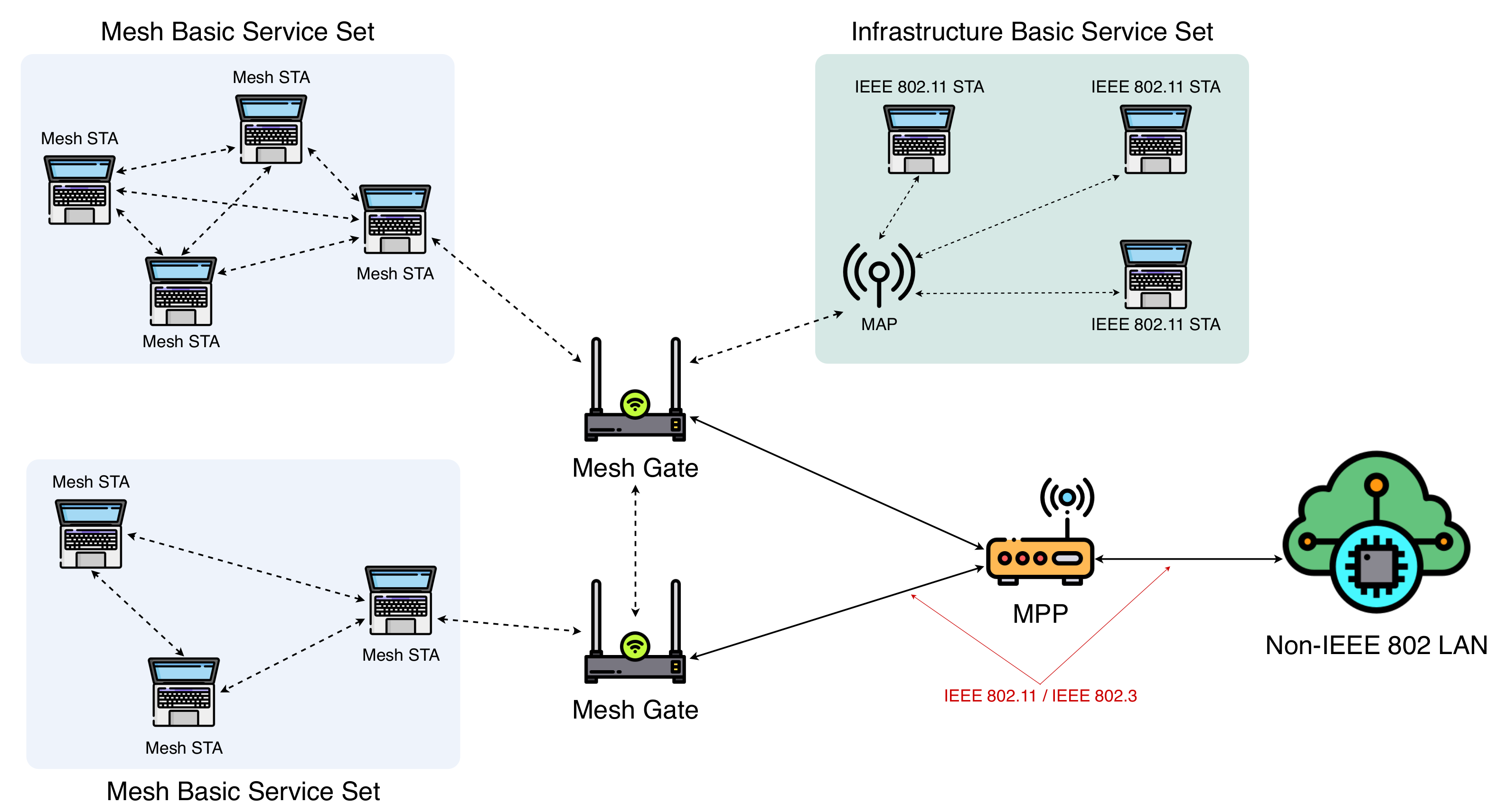
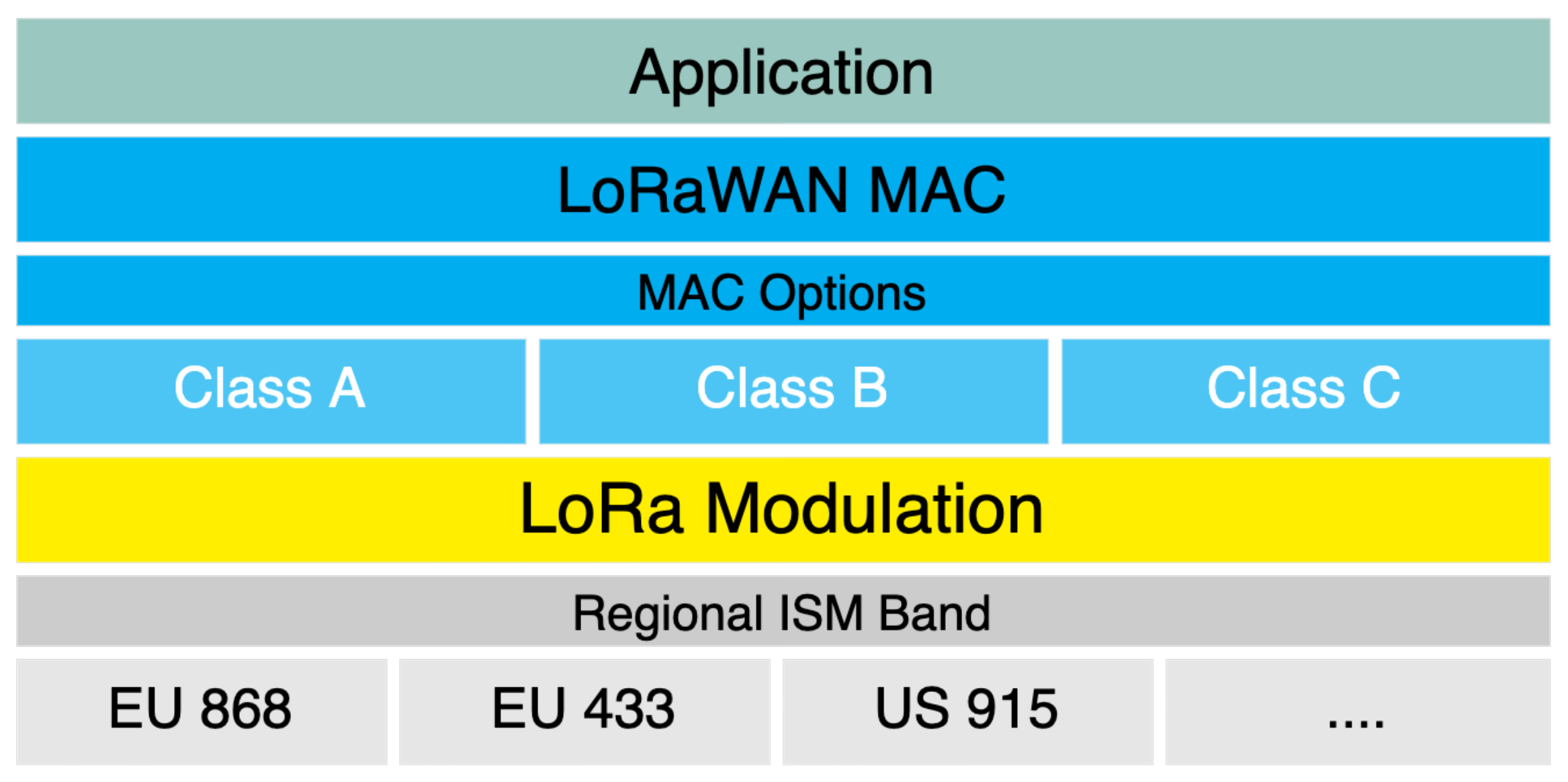
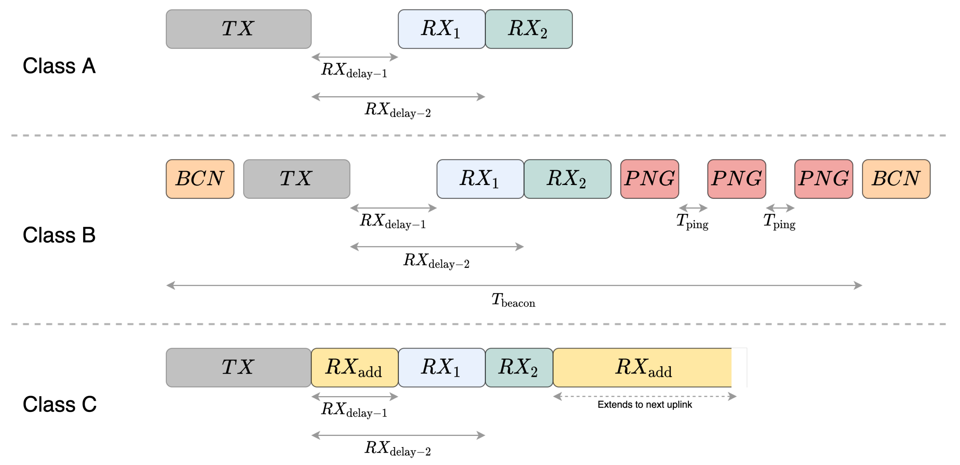
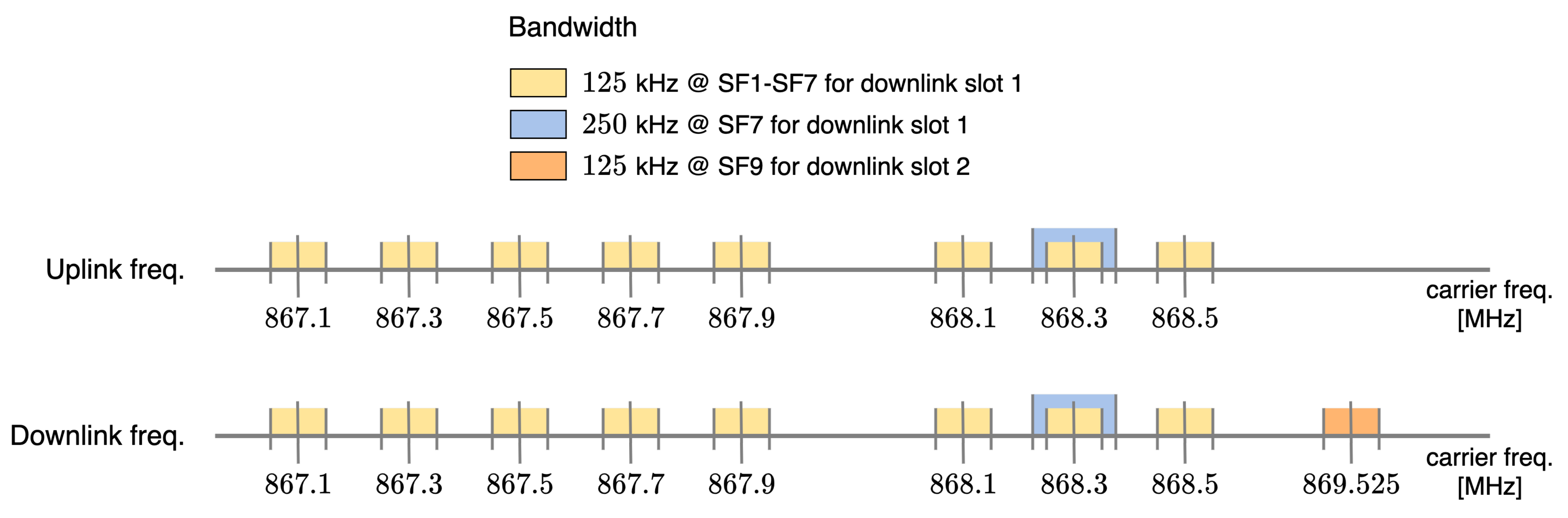
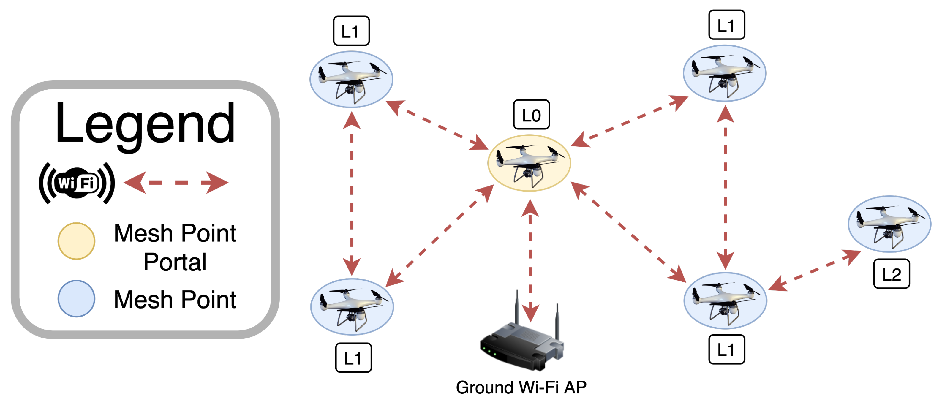
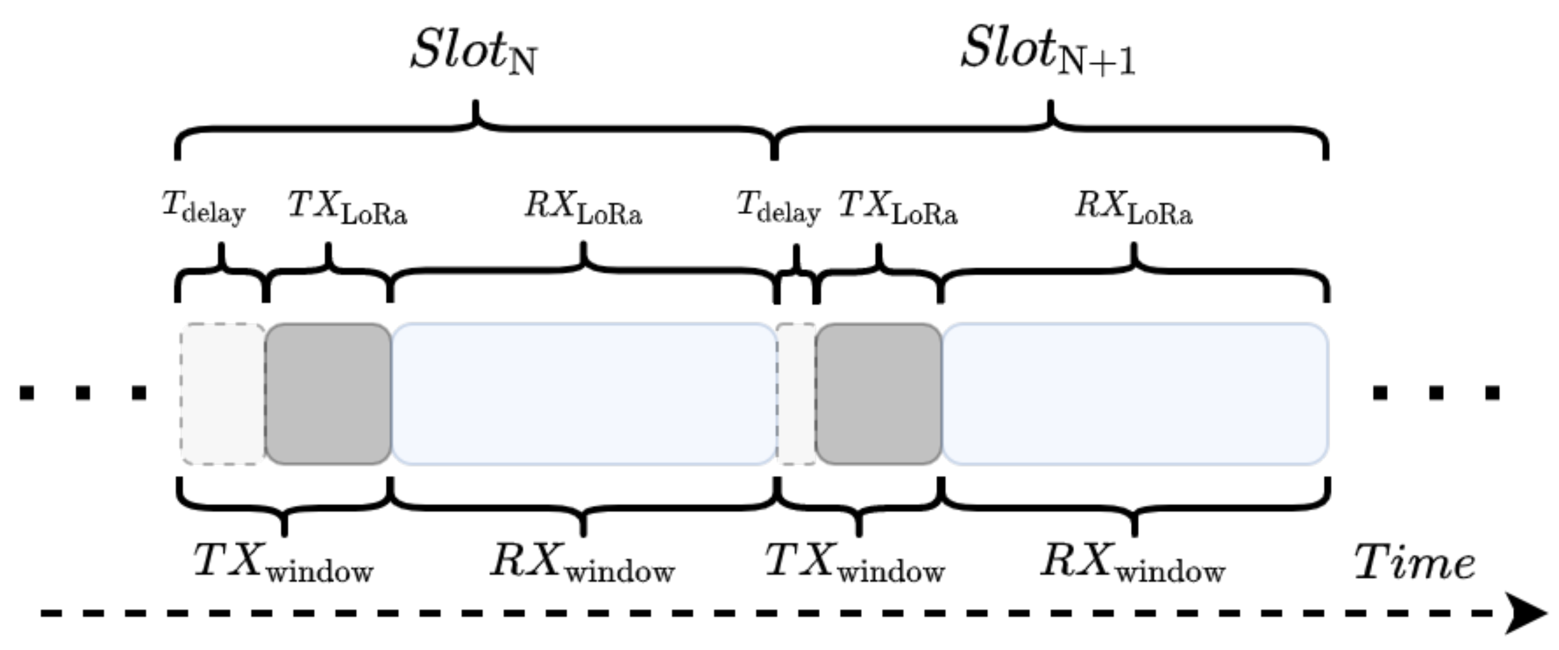
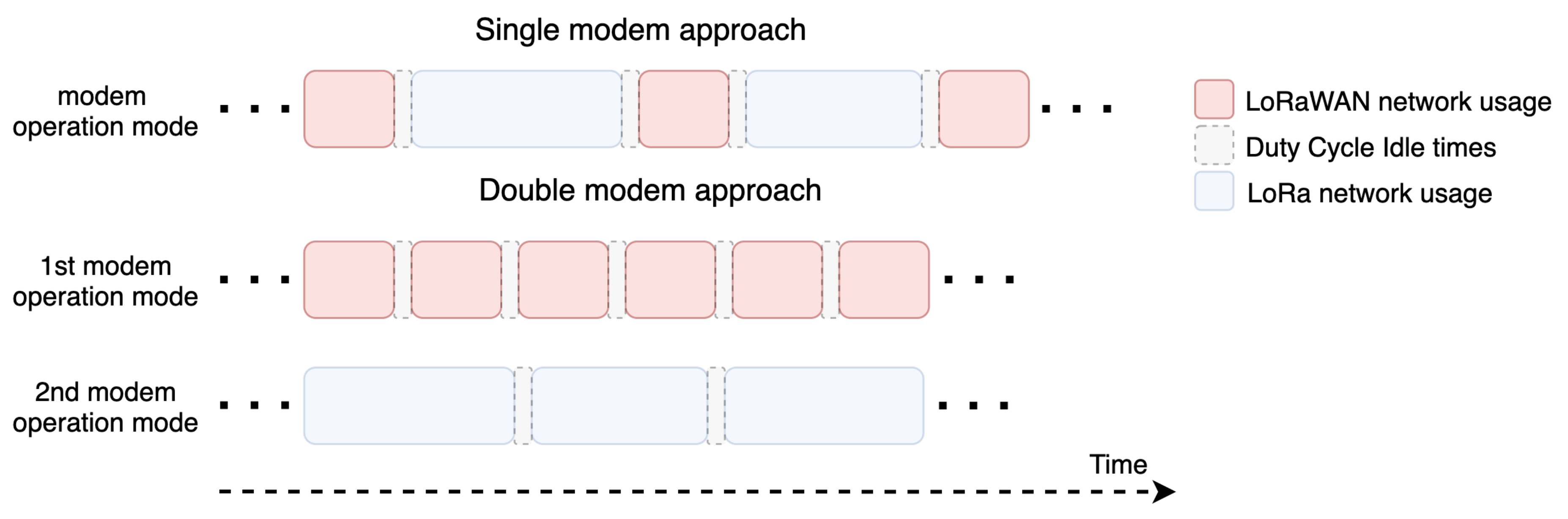
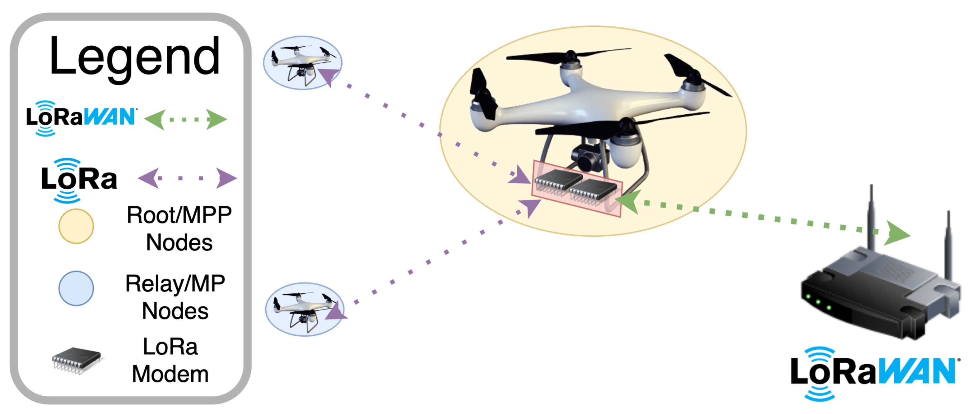
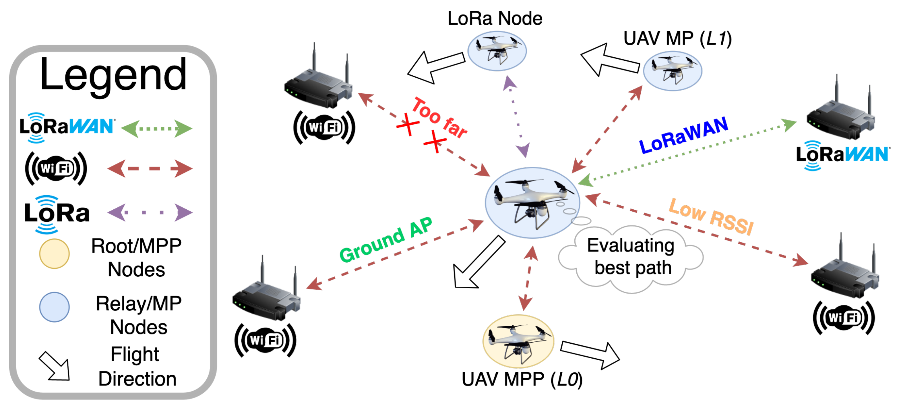
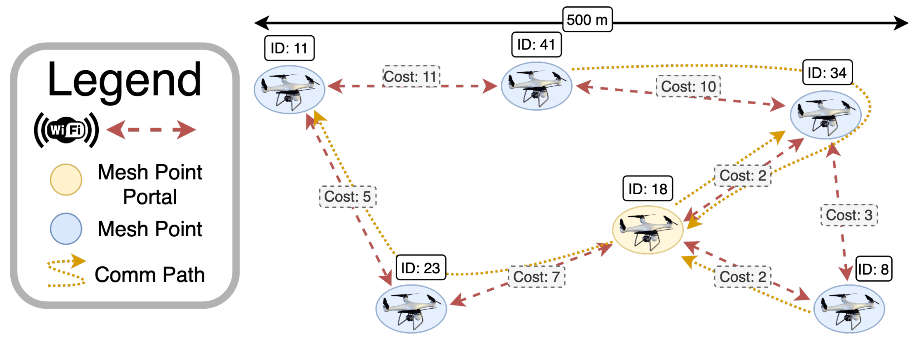
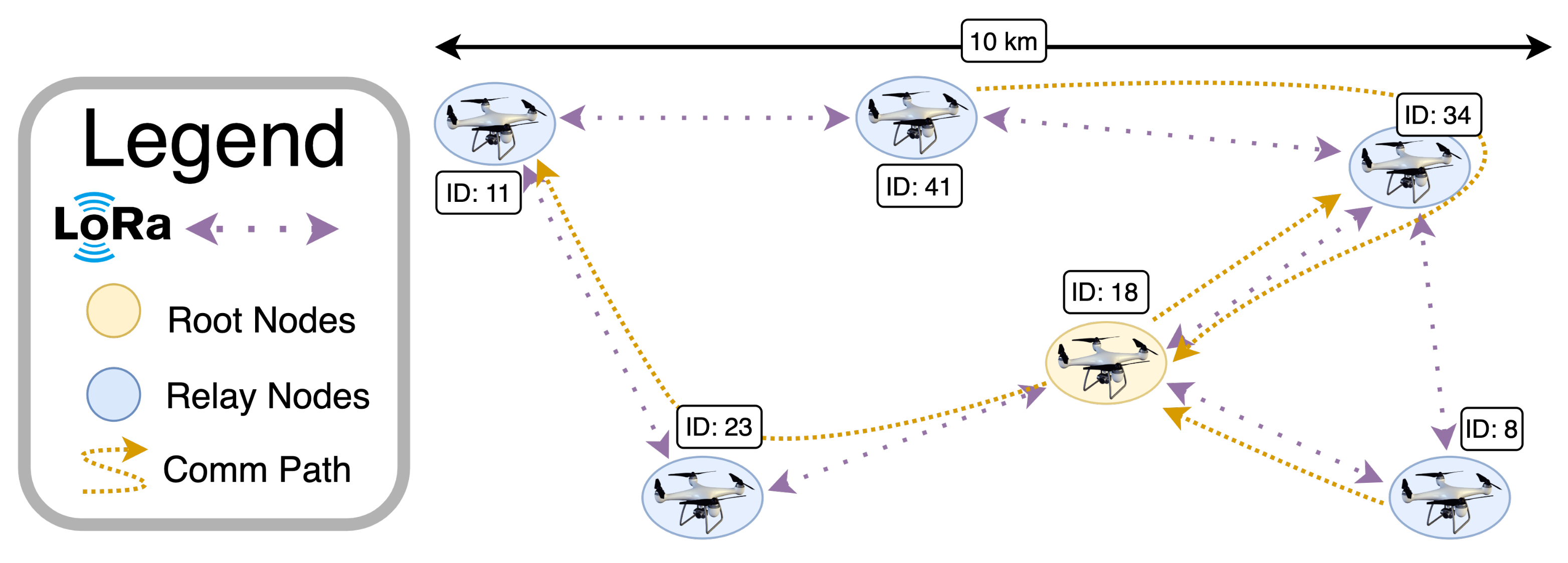
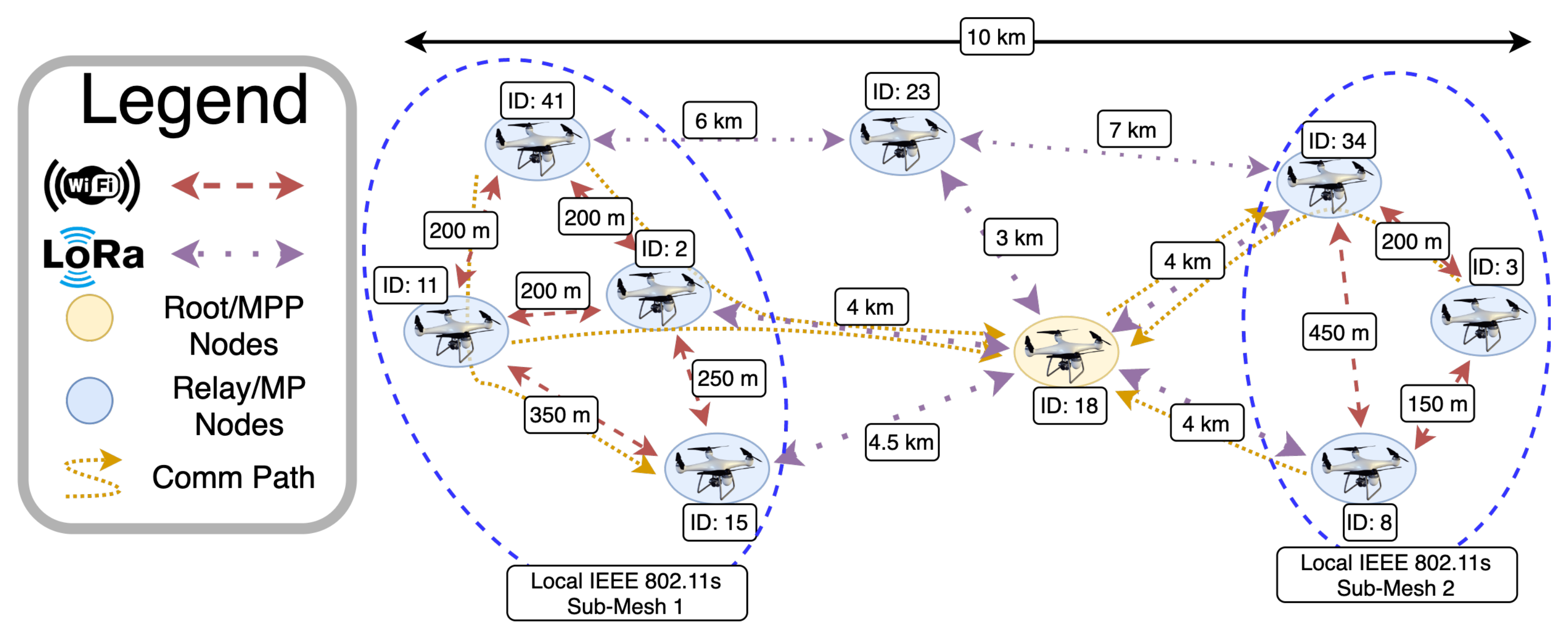
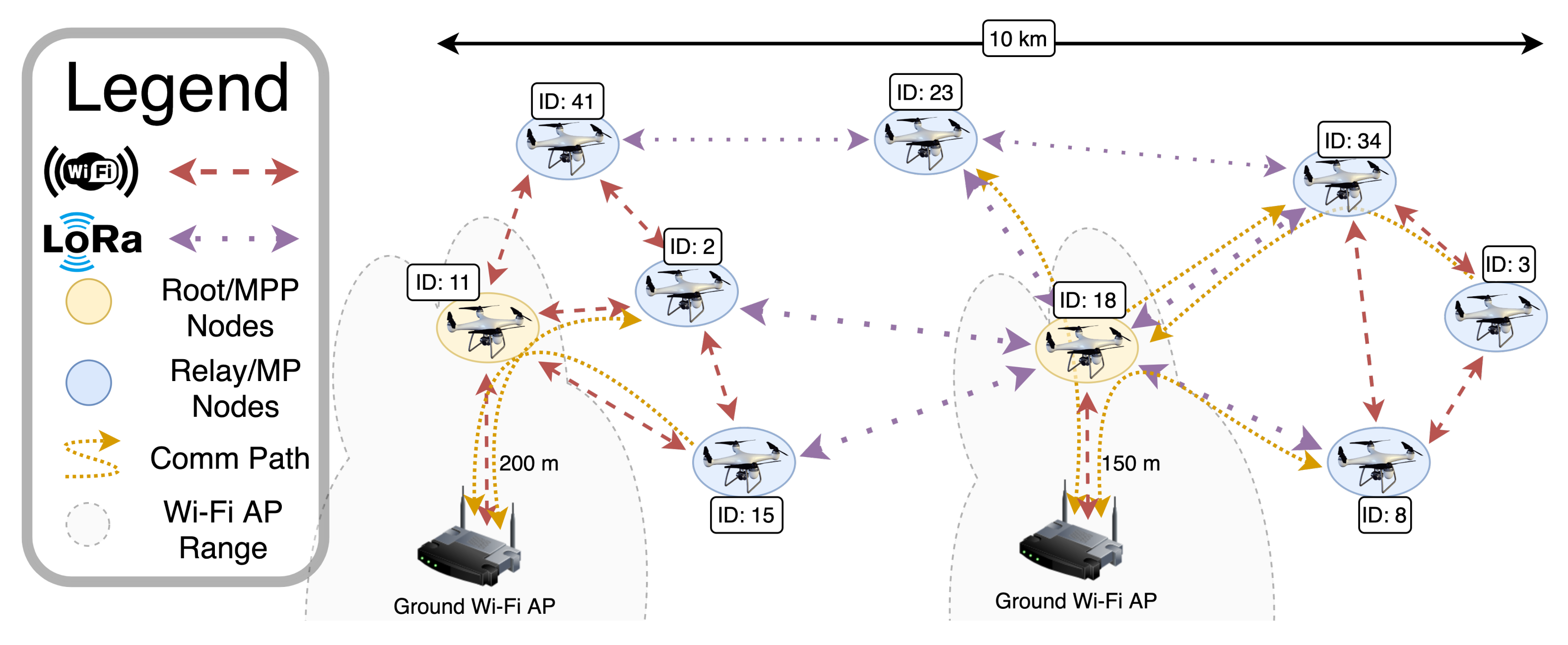
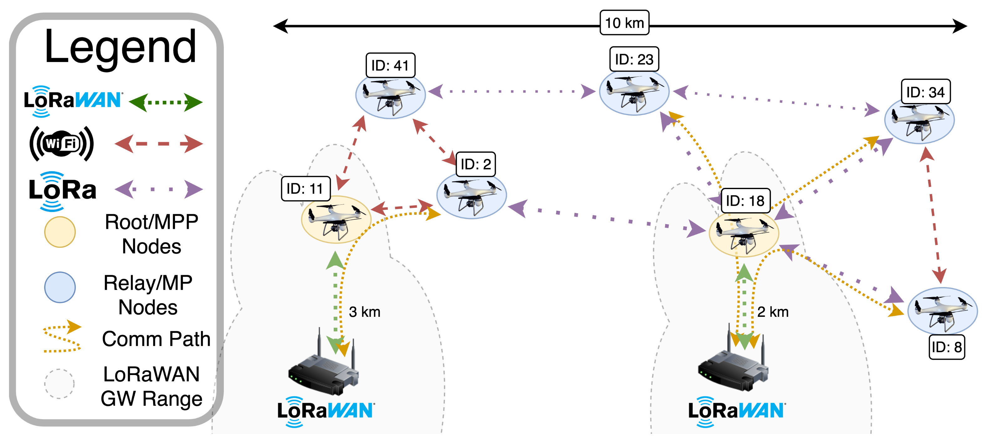
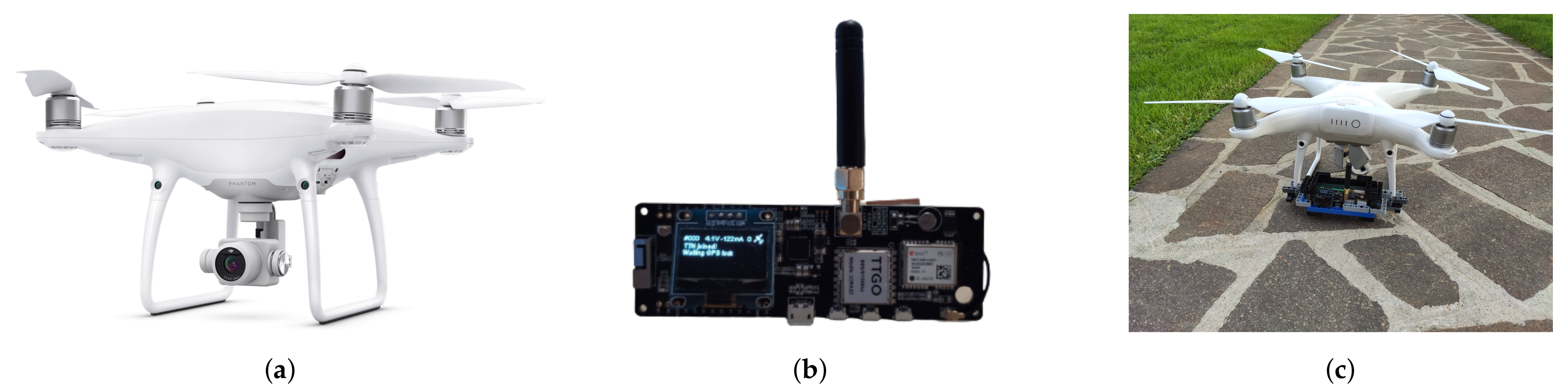
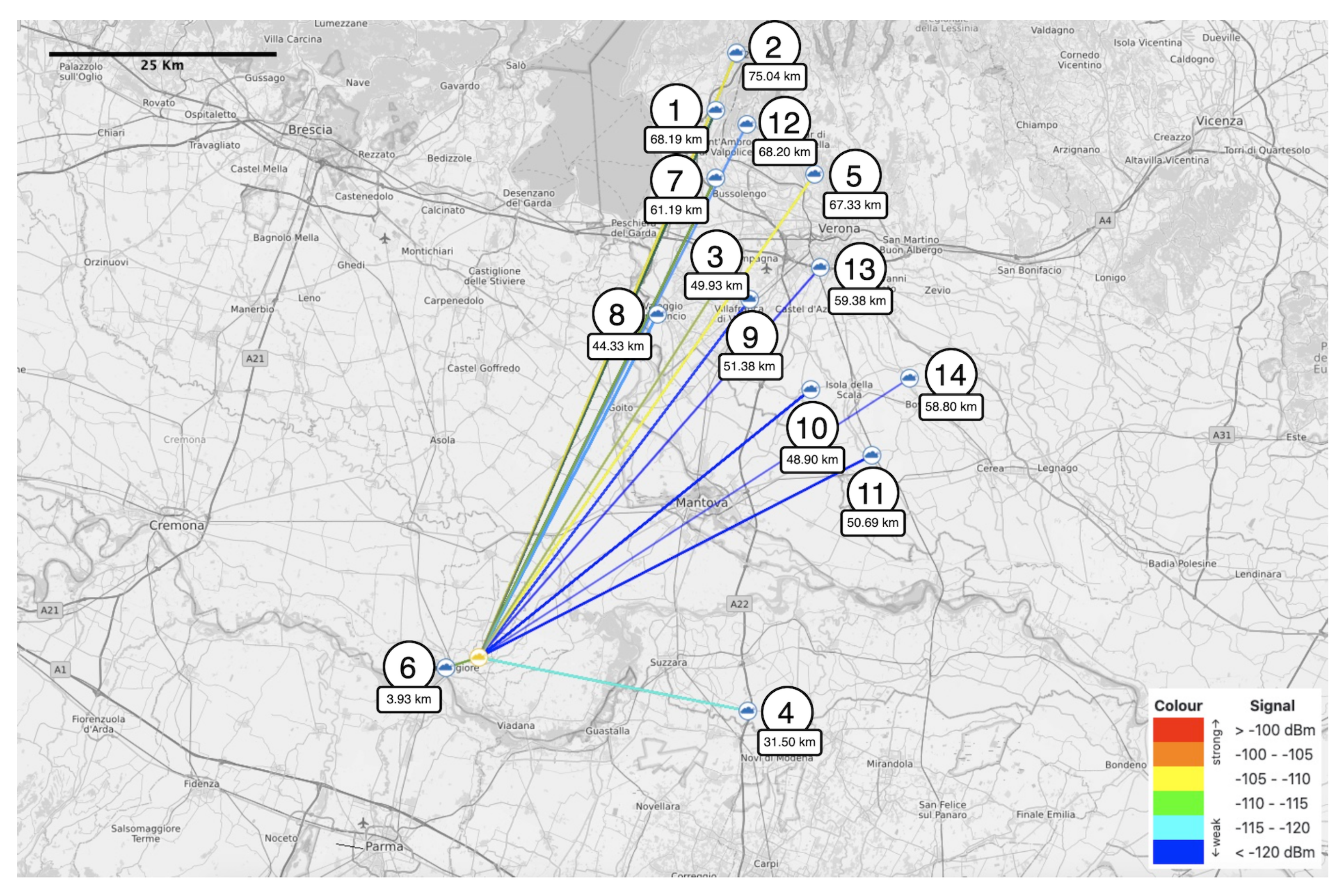
Table 1.
LoRaWAN transmission parameters on the basis of the adopted SF. In all cases, the bandwidth is 125 kHz and the CF is set to 868 MHz.
Table 1.
LoRaWAN transmission parameters on the basis of the adopted SF. In all cases, the bandwidth is 125 kHz and the CF is set to 868 MHz.
| Spreading Factor [SF] | Data Rate [DR] [55] | Bitrate [Bit/Sec] | Range [km] | RX Sensitivity [dBm] | Max Payload [Bytes] |
|---|---|---|---|---|---|
| 12 | 0 | 290 | 12+ | −136 | 51 |
| 11 | 1 | 440 | 10 | −133 | 51 |
| 10 | 2 | 980 | 8 | −132 | 51 |
| 9 | 3 | 1760 | 6 | −129 | 115 |
| 8 | 4 | 3125 | 4 | −126 | 222 |
| 7 | 5 | 5470 | 2 | −123 | 222 |
Table 2.
LoRaWAN UAV-to-ground range test results.
| GW Number (#) | GW Distance (km) | Average RSSI (dBm) | Received Packets (with Respect to Sent Packets) | Received Packets (%) |
|---|---|---|---|---|
| 1 | 68.199 | −113.72 | 69 of 72 | 95.83 |
| 2 | 75.040 | −110.16 | 69 of 72 | 95.83 |
| 3 | 49.936 | −110.05 | 61 of 72 | 84.72 |
| 4 | 31.505 | −113.13 | 60 of 72 | 83.33 |
| 5 | 67.339 | −107.98 | 57 of 72 | 79.17 |
| 6 | 3.933 | −107.09 | 56 of 72 | 77.78 |
| 7 | 61.193 | −113.73 | 49 of 72 | 68.06 |
| 8 | 44.330 | −116.53 | 40 of 72 | 55.56 |
| 9 | 51.385 | −118.86 | 35 of 72 | 48.61 |
| 10 | 48.904 | −117.10 | 30 of 72 | 41.67 |
| 11 | 50.691 | −118.25 | 12 of 72 | 16.67 |
| 12 | 68.206 | −116.20 | 5 of 72 | 6.94 |
| 13 | 59.384 | −114.75 | 4 of 72 | 5.56 |
| 14 | 58.800 | −118.67 | 3 of 72 | 4.17 |
Publisher’s Note: MDPI stays neutral with regard to jurisdictional claims in published maps and institutional affiliations. |
© 2021 by the authors. Licensee MDPI, Basel, Switzerland. This article is an open access article distributed under the terms and conditions of the Creative Commons Attribution (CC BY) license (https://creativecommons.org/licenses/by/4.0/).
Share and Cite
MDPI and ACS Style
Davoli, L.; Pagliari, E.; Ferrari, G. Hybrid LoRa-IEEE 802.11s Opportunistic Mesh Networking for Flexible UAV Swarming. Drones 2021, 5, 26. https://0-doi-org.brum.beds.ac.uk/10.3390/drones5020026
AMA Style
Davoli L, Pagliari E, Ferrari G. Hybrid LoRa-IEEE 802.11s Opportunistic Mesh Networking for Flexible UAV Swarming. Drones. 2021; 5(2):26. https://0-doi-org.brum.beds.ac.uk/10.3390/drones5020026
Chicago/Turabian StyleDavoli, Luca, Emanuele Pagliari, and Gianluigi Ferrari. 2021. "Hybrid LoRa-IEEE 802.11s Opportunistic Mesh Networking for Flexible UAV Swarming" Drones 5, no. 2: 26. https://0-doi-org.brum.beds.ac.uk/10.3390/drones5020026