
A Novel Link Failure Detection and Switching Algorithm for Dissimilar Redundant UAV Communication


Department of Mechanical Engineering, Faculty of Engineering, National University of Singapore, 9 Engineering Dr 1, Singapore 117575, Singapore
*
Author to whom correspondence should be addressed.
Drones 2021, 5(2), 48; https://0-doi-org.brum.beds.ac.uk/10.3390/drones5020048
Submission received: 3 May 2021
/
Revised: 25 May 2021
/
Accepted: 28 May 2021
/
Published: 1 June 2021
(This article belongs to the Special Issue Unmanned Aerial Vehicle-Assisted Cooperative Air and Ground Communications)
Abstract
:Unmanned Aerial Vehicles (UAVs) used for humanitarian applications require simple, accessible and reliable components. For example, a communication system between UAV and the Ground Control Station (GCS) is essential in order to monitor UAV status; various communication protocols are available in the industry. Such systems must be simple for non-technical personnel (e.g., healthcare workers) to operate. In this study, a novel link failure detection and switching algorithm was proposed for a dissimilar redundant UAV communication system designed for long-range vaccine delivery in rural areas. The algorithm would ease the workload of the operators and address a research gap in the design of such algorithms. A two-layer design is proposed: A baseline layer using the heartbeat method, and optimisations to speed up local failure detection. To dynamically tune the heartbeat timeout for the algorithm’s baseline without intervention from ground operators, the modified Jacobson’s algorithm was used. Lab simulations found that the algorithm was generally accurate in converging to an optimal value, but has less satisfactory performance at poor or unpredictable connectivity, or when link switches get triggered frequently. Improvements have been suggested for the algorithm. This study contributes to ongoing research on ensuring reliable UAV communication for humanitarian purposes.
1. Introduction
1.1. Background
There is an increasing demand for UAVs to be deployed for humanitarian purposes. They have been used as low-cost, rapid-response platforms, performing damage assessments in disaster zones such as the city of Tacloban during Typhoon Haiyan [1], and for transporting medical supplies in rural areas [2]. The biennial UAV Outback Challenge held in Australia serves as a testing ground for developing Unmanned Aerial Systems (UAS) capable of search and rescue (SAR) operations [3].
Humanitarian UAS are often operated by non-technical personnel such as healthcare or rescue personnel; hence they must be user friendly [2]. The design of the UAS must be simple and accessible, yet reliable. For example, reliable communication is required between the UAV and GCS, so that the ground operators can monitor the UAV status or execute mission critical commands. At the same time, the system should be sufficiently autonomous such that minimal interventions are required during a mission, so that the ground operators would not be overwhelmed by the complexity of operations [4].
1.2. Objective
The study was conducted as part of a project by Yonah Pte Ltd. [4], a Singapore based social enterprise that aims to develop UAS for humanitarian purposes. The objective was to design a failure detection and switching algorithm for Yonah’s dissimilar redundant UAV communication system, which was designed for long-range vaccine transport in rural areas.
The algorithm should automatically detect failure in a link, and switch to another link with minimal downtime and no intervention from the operators. The purpose was to ease the operating workload and make the system simple for non-technical personnel to handle.
The remainder of Section 1 analyses Yonah’s existing UAV communication system, and compares it with existing research to figure out how to approach the problem. Section 2 details the algorithm design and the methods used to test it. Section 3 shows the test results, Section 4 discusses the results, and a conclusion is presented in Section 5.
1.3. Analysis of Yonah’s Software
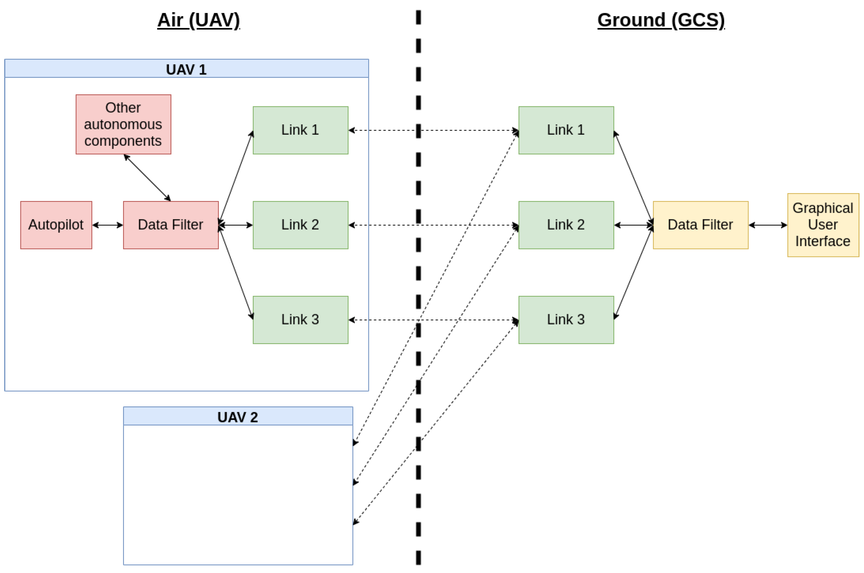
Yonah’s existing UAV communication system is shown in Figure 1. It utilised three dissimilar communication protocols. The software architecture was based on a Robot Operating System (ROS) framework, with each box in Figure 1 representing an ROS Node. Using ROS allowed for a modular design and easy communication across different nodes. The solid arrows represent inter-node communication through ROS topics and services. The dotted arrows represent link-specific communication. Refer to Appendix A for a detailed explanation of the communication system design.
The dissimilar communication protocols for the Link Nodes 1–3 are listed in Table 1: Cellular, Short-Message-Service (SMS) and satellite.
An analysis of Yonah’s communication architecture showed that the links in Table 1 were selected for their simple design, easy accessibility in rural environments, and ability to provide reliable, long-range communication. Yonah did not implement radio communication—the traditional communication method in the UAV industry—because radio is limited to line-of-sight operation and is susceptible to blockage [5]. To extend to BVLOS, repeater stations such as antenna masts and satellite dishes are necessary [6]. In extreme circumstances, additional UAVs acting as aerial relays can and have been used [7]. These measures require specialised equipment which are difficult to access and set up in rural areas.
Instead, Yonah used accessible and long-range protocols. The cellular link communicated on LTE/3G networks while the SMS link was a 2G fallback; these cellular networks are ubiquitous and can operate BVLOS [8]. Such capabilities were critical for Yonah’s operations, which required its drones to have an operational radius of up to 100 km in rural areas [4]. Other UAS such as the LARUS Project also proposed LTE communication for UAV SAR missions, and found that such methods could provide reliable communication of up to 99.8% availability [9,10].
However, the cellular and SMS links were limited to regions with cellular coverage, which is not a guarantee in rural environments. Thus, the satellite link served as the final backup when there is no cellular signal. The link used Iridium’s global satellite constellation to transmit text messages using the Short Burst Data (SBD) protocol, making it usable in areas that would otherwise be unreachable by cellular networks [11].
Dissimilar redundancy was used to provide a progressive fallback if the UAV were to fly into regions with successively decreasing cellular coverage. “Diversifying” the protocols helps to reduce the probability of common-mode failure [12], and is not a new concept in the drone industry. For example, HydraCom’s UAS communication used dissimilar redundant LTE and radio telemetry [5]. Hence, communication could be maintained through radio even if there was no LTE coverage, similar to Yonah’s communication architecture.
However, there were two drawbacks in Yonah’s architecture. First, all links have higher latency and packet loss rate compared to radio. For the cellular and SMS links, the antennae of cellular towers are tilted downwards to optimise coverage for ground users, which makes them less suitable for aerial users [10]. Studies on UAS LTE-based infrastructure showed that interference between UAVs and other network users can affect network availability, and UAVs do not always associate to the nearest cell tower due to different radiation patterns on ground and in the air [13]. For the satellite link, the higher the satellite, the longer the round-trip-time (RTT) between UAV and GCS; for example, geostationary satellites have RTT = 0.5 s [14]. While it is possible to lower the latencies by using low-earth-orbit satellites, such systems have a higher handover frequency compared to other satellite systems, which will lead to higher packet loss during a handover [14].
Second, the SMS and satellite links were metered and would cost money for each transmitted message. For example, to send a text message of 50 bytes or less through Iridium SBD, the Rockblock 9603 modem charges on average 0.1 pounds per message [15]. As a result, the system could not send messages at too high a frequency on these links or it would drive up the cost of operation. These disadvantages would have significant impacts on the design of the link switching algorithm.
1.4. Existing Research on Reliable UAV Communication
Most ongoing research on ensuring reliable UAV communication focuses on the following:
Most of the ongoing efforts are geared towards analysing and minimising the packet loss, so as to ensure maximum availability in UAS communication. It is apparent that dealing with loss and communication breakdown are inevitable. This highlights the need to detect link failure and take necessary measures.
The focus of this study was to find out how to detect failure in any link and fall back to another with minimal downtime strategy in between. A common way to detect failure in a computer network is the heartbeat method: Nodes send periodic heartbeat messages to one another; failure to receive messages from any node indicates communication loss [18]. For UAS with multiple redundant links, a common practice is to broadcast heartbeats on all links at the same time; any link marked as down would not be used. This method is frequently used in commercial UAS applications such as the Micro Air Vehicle (MAVlink) protocol [19]. It is a simple practice that works well for low-latency UAV links, and eliminates the need for link switching algorithms. Thus, there is a research gap when it comes to designing failure detection and switching algorithms for UAV communication.
However, the heartbeat method has two problems. For high latency infrastructure, the delay between occurrence and detection of link failure can be significant, especially affecting time-critical applications such as drone operations. Moreover, if the links are metered, then the method of broadcasting heartbeats on all links would drive up the operating cost. It turns out that these problems are the same drawbacks identified in Yonah’s communication architecture! Therefore, it was essential to address the research gap in the design of link switching algorithms to improve Yonah’s architecture.
2. Materials and Methods
In this section, the overall link switching algorithm design is first detailed. Next, the method used to tune an important parameter in the first algorithm is discussed. Finally, the methods used to test these algorithms are listed.
2.1. Algorithm Design
In the context of UAV communication, two types of link failure could occur: Local and remote. For example, if a failure occurs on the ground side, it was perceived as a local failure for the ground operator and a remote failure for the UAV, and vice-versa.
There were multiple options to detect local failure. First, the heartbeat method could be used. A faster option would be to directly use the link signal strength as an indication, similar to how mobile phone users determine the cellular connectivity in their area by checking their phone signal strength. For example, if the local internet connection were to drop below a threshold value, it would indicate failure in the cellular link. While such options were faster than the heartbeat method, they could not detect remote failure. For example, the UAV would not be able to probe the internet connection of the GCS to check if there is loss of signal on the ground side, unless they were in close proximity to each other! The only way to detect remote failure was for the remote end to notify the local end of any failure, which led back to the heartbeat method.
The proposed link switch algorithm used a two-layer design:
- A baseline layer based on the heartbeat method, to detect both local and remote failure.
- Optimisations based on link signal strength, to speed up detection of local failure.
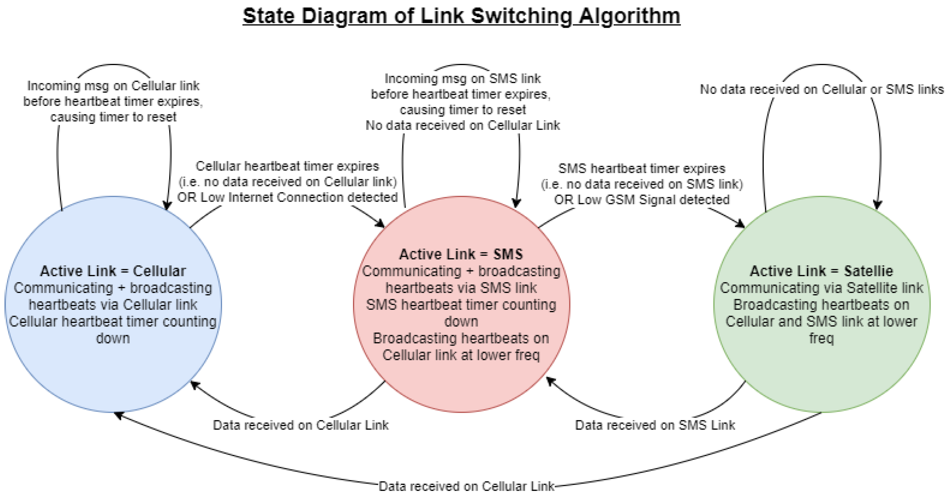
The state diagram of the algorithm is given in Figure 2. The system would start on the primary link (Cellular), with both air and ground broadcasting heartbeats to each other at periodic intervals. The other two links would be dormant. Two events trigger a link switch: (1) When no heartbeats are received within a certain timeout period (heartbeat method), (2) When the local LTE/3G connection drops below a threshold (optimisations). When the system switches to the first backup (SMS), heartbeats would be exchanged via SMS; heartbeats would still be broadcast on the cellular link to check if the link was restored, but at a lower frequency to save cost. If data is received on the cellular link, a link switch would be triggered back. However, if the cellular link continues to remain down and the SMS link fails as well, then a link switch would be triggered to the final backup (satellite).
The algorithm design made an assumption that the satellite link was always operational, since it had global coverage. This simplified the design by (1) Not having to take into account the scenario where all 3 links go down, (2) Limiting any broadcasting to the cellular and SMS links, since there was no need to detect failure in the satellite link.
2.2. Parameter Tuning
One key parameter for the algorithm’s baseline heartbeat method must be tuned: The time taken for each link’s timer to count down to zero, or the heartbeat timeout. Too long an interval would cause slow response to failure. Too short would trigger false positives.
The time between reception of an incoming heartbeat message and reception of the next was defined as the Trip Time (TT), with a mean and standard deviation under steady-state conditions. In an ideal world, an appropriate interval could be set if the TT and were known; the interval would be equal to with a safety factor based on . However, it required the ground operator to have in-depth knowledge of the flight environment’s network latency, which was not practical in humanitarian applications.
Was it possible for the algorithm to calculate and by itself? It turned out that there existed a solution in the computer networking field; the Jacobson’s algorithm employed in Transmission Control Protocol (TCP) networks dynamically calculates Round-Trip-Time (RTT) and given enough network traffic, and uses them to calculate a Round-Trip-Timeout (RTO) value [20]. The pseudocode is provided in RFC6298 [21].
By relating TT with RFC6298’s RTT, and the heartbeat timeout with RFC6298’s RTO, Jacobson’s algorithm could be adopted for calculating the heartbeat timeout of the link switch algorithm. The link switch algorithm could then dynamically calculate an optimal heartbeat timeout without prior knowledge required by the ground operator. The modified version of Jacobson’s algorithm was used in this study as follows. As heartbeats come in and the true TT value between each heartbeat is sampled, the and of these samples (SampledTT) are estimated using Equation (1).
and indicate how much weightage is given to the latest TT samples; the recommended values of = 0.125 and = 0.25 were adopted from RFC6298 [21]. The heartbeat timeout interval is estimated by setting it to , with an added safety factor based on and the precision of the software operating system, defined as the clock granularity (G). The result is given by Equation (2).
The safety factor is deliberately kept conservative; 4 × would cover almost all samples in a normal distribution, with G adding another layer of safety. Equations (1) and (2) are adopted directly from the original Jacobson’s algorithm.
However, Equation (1) is recursive, which means and are dependent on their own previous values. How should the initial values of and be set? Determining the initial values was relevant either immediately on system startup, or after restoration of a link that had previously failed (henceforth defined as link recovery). There were two scenarios to consider:
- When no TT samples are taken yet.
- Upon receiving the first TT sample.
For Scenario 1, RFC6298 specifies that the timeout value should be set to a value of 1 s or less. For Scenario 2, RFC6298 specifies that should be set to be equal to the first TT sample, should be half of , and Equation (2) used to calculate the timeout. This would give a timeout value that is thrice that of the first TT sample measurement [21].
In Yonah’s operational context, the recommended value of 1 s for Scenario 1 was too short in rural areas with poor connectivity [4]. Moreover, when the link has just recovered, it would previously be transmitting at longer time intervals (defined as ) as specified by Figure 2. When one side of the link (e.g., UAV side) recovers and starts the timer, the other side (e.g., GCS side) might still be broadcasting at as it had not received the link recovery command; thus the former side should wait for a time interval based on .
In this study, the modified Jacobson algorithm tackled the setting of initial and as follows. For Scenario 1, the initial heartbeat timeout was set to . This method merged RFC6298’s handling with the unique requirements of the link switch algorithm described earlier. For Scenario 2, the recommendations from RFC6298 was directly adopted (i.e., setting the heartbeat timeout to thrice of the first TT sample).
Finally, one last edge case must be considered. For the cellular link, during link failure, messages sent out might hang indefinitely in the cloud, and flood in when the link recovered. Such a flooding would affect the calculation of the heartbeat timeout if left unchecked. Thus, another modification was made to ignore all incoming messages that were transmitted after link failure and prior to link recovery.
The final modified version of Jacobson’s algorithm was thus given in Equations (1) and (2) along with the stated modifications. This algorithm was used to calculate an optimal heartbeat timeout of the link switch algorithm.
2.3. Lab Simulations
This section covers the lab simulations used to stress test the integrity of the link switch algorithm, particularly the effectiveness of Jacobson’s algorithm in converging to an optimal heartbeat timeout value. The initial plan was to perform flight tests in rural areas with high network latency. However, restrictions due to the Covid-19 pandemic made flight tests impossible. It was also challenging to source for physical locations in Singapore with poor connectivity.
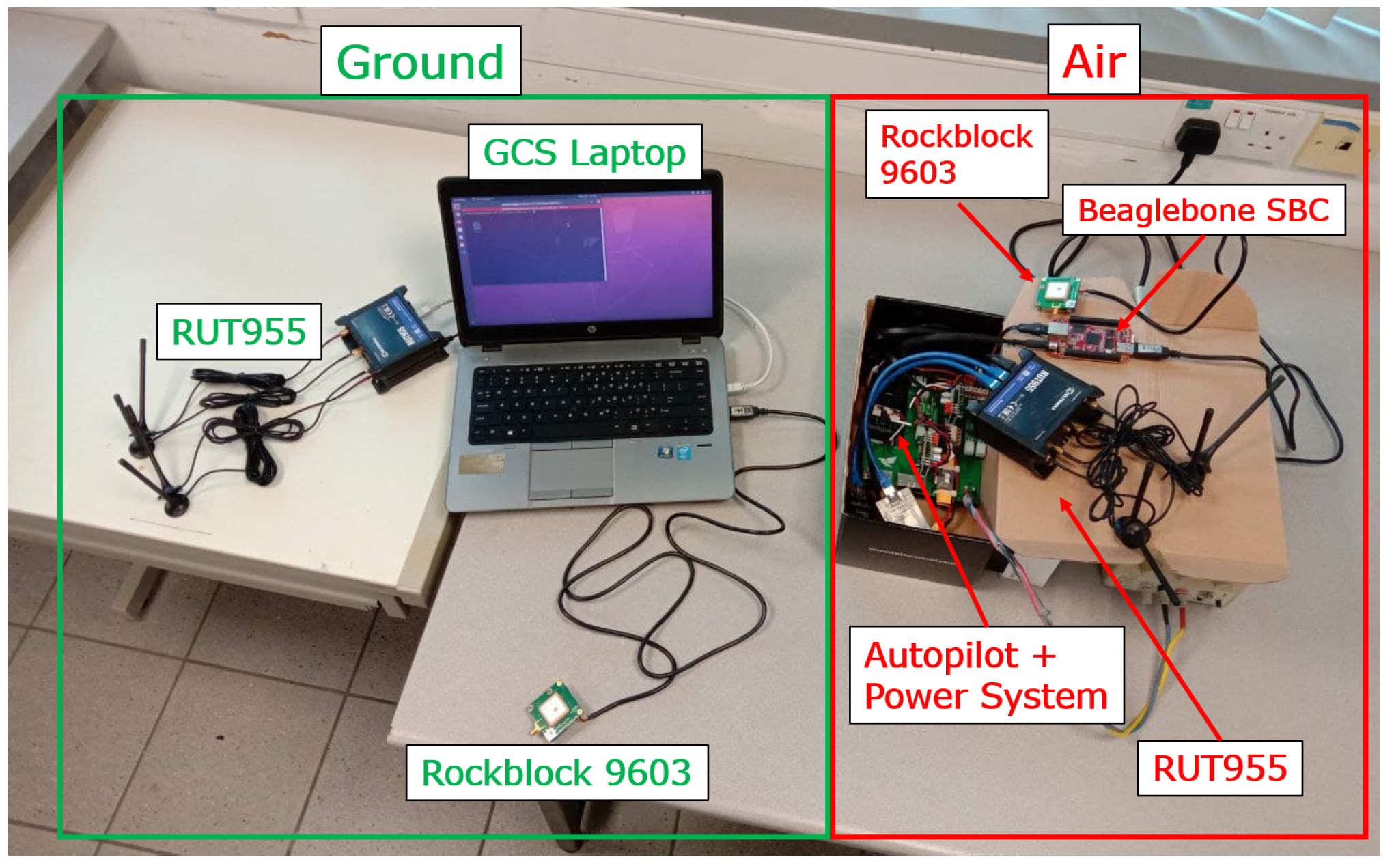
To overcome this problem, lab tests were performed with the UAV avionics on a ground-based platform, and a GCS laptop. The code was modified to artificially introduce a delay into the links, with the delay calculated using user-input and . This modification effectively simulated high latency. The experimental setup is shown in Figure 3. A guide to reproducing the experimental results is in Appendix B.
For the tests, a few assumptions were made:
- All three links in Yonah’s communication system would have similar heartbeat timeout calculation behaviour when subjected to Jacobson’s algorithm. To save time, only the cellular data link was tested.
- The actual latency of the physical environment was negligible compared to the simulated latency.
A test run was defined as the following:
- The clock granularity was set to 1 s.
- Values were specified for and .
- Both air and ground were left to communicate with each other over the cellular link for 3 min.
- The experimental heartbeat timeout and the true TT value was logged.
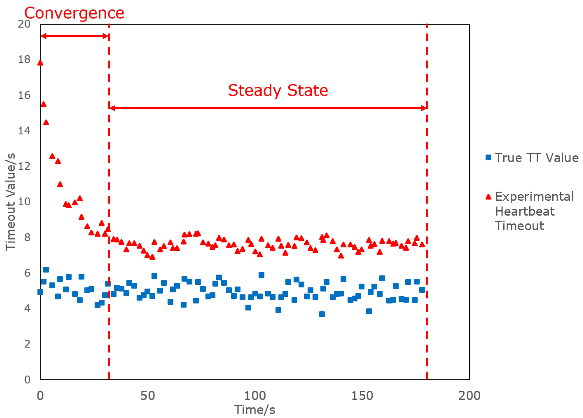
Figure 4 represents a typical test run where the heartbeat timeout calculated by Jacobson’s algorithm starts at a conservative value, before converging to the true TT value with an added safety factor. The convergence and steady state phases can be clearly seen; hence the convergence time and mean heartbeat timeout value at steady state can be calculated.
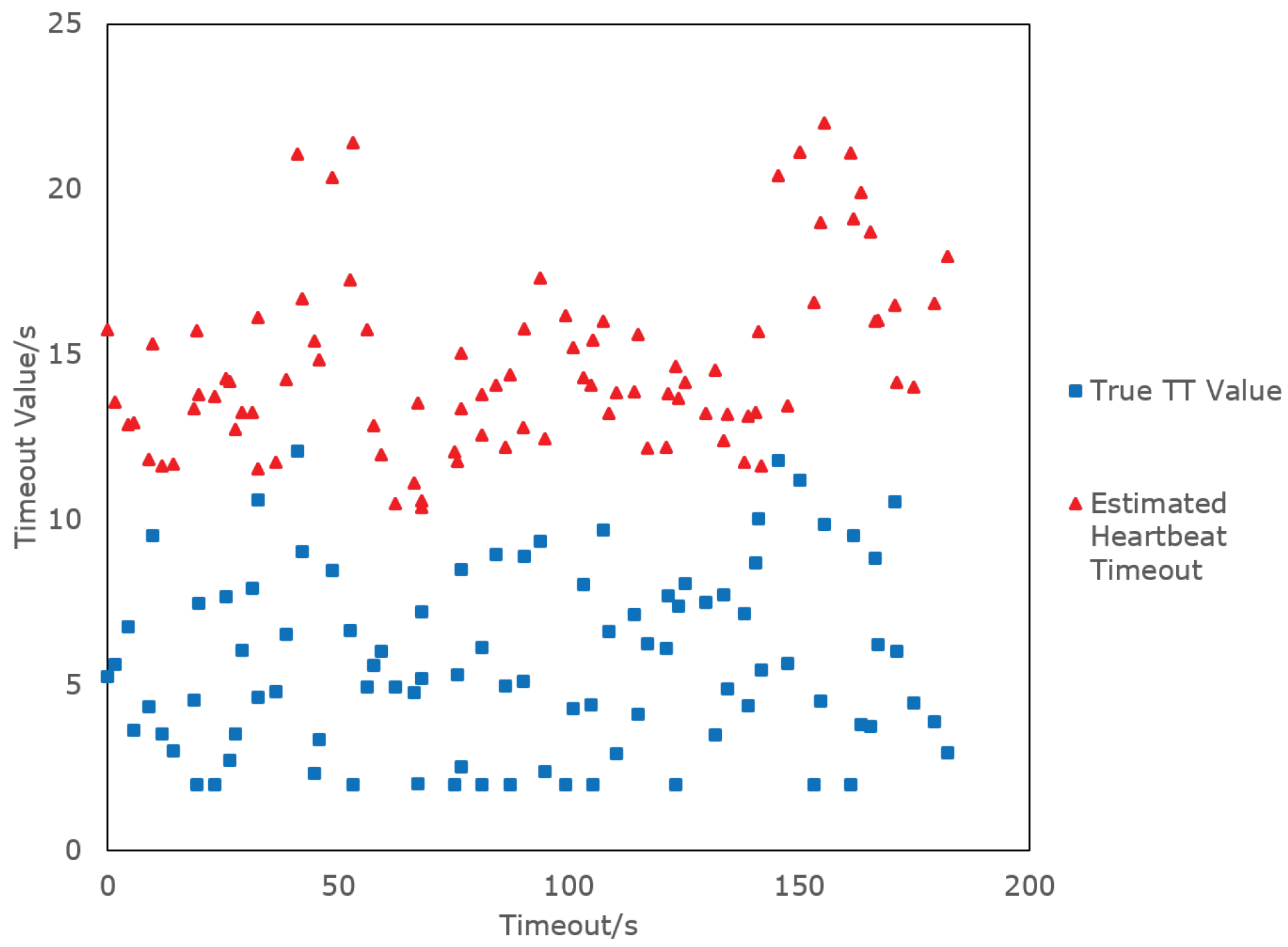
Figure 5 represents a situation where there is no observable convergence. In this situation, the convergence time is assumed to be infinite. The mean heartbeat timeout at “steady state” can still be calculated, albeit with a large standard deviation.
Three experiments were performed:
- was varied while was kept constant at 0 s for varying test runs.
- was varied while was kept constant at 5 s for varying test runs.
- With = 5 s and = 0.1 s, the test run was modified as follows: At the 20 s mark, the ground side was disconnected to simulate a link failure. The link was re-connected after another 20 s.
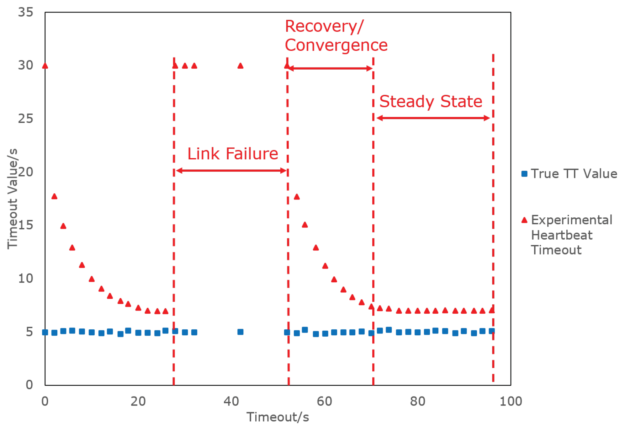
An example of the modified test run in Experiment 3 is shown in Figure 6, with the link loss, recovery/convergence and steady state phases highlighted:
For all experiments, each test run for a particular value of and was repeated thrice.
For Experiments 1 and 2, the purpose was to observe the effectiveness of the Jacobson algorithm in converging to an optimal heartbeat timeout value. The following were calculated for each value of and : (1) Average time taken for the experimentally calculated heartbeat timeout to converge to steady state; (2) average value of the steady state heartbeat timeout.
For Experiment 3, the purpose was to observe the effects of link failure and recovery on the calculated value of the heartbeat timeout. The test run plots were qualitatively observed during disconnection and re-connection.
3. Results
4. Discussion
4.1. Experiments 1 and 2
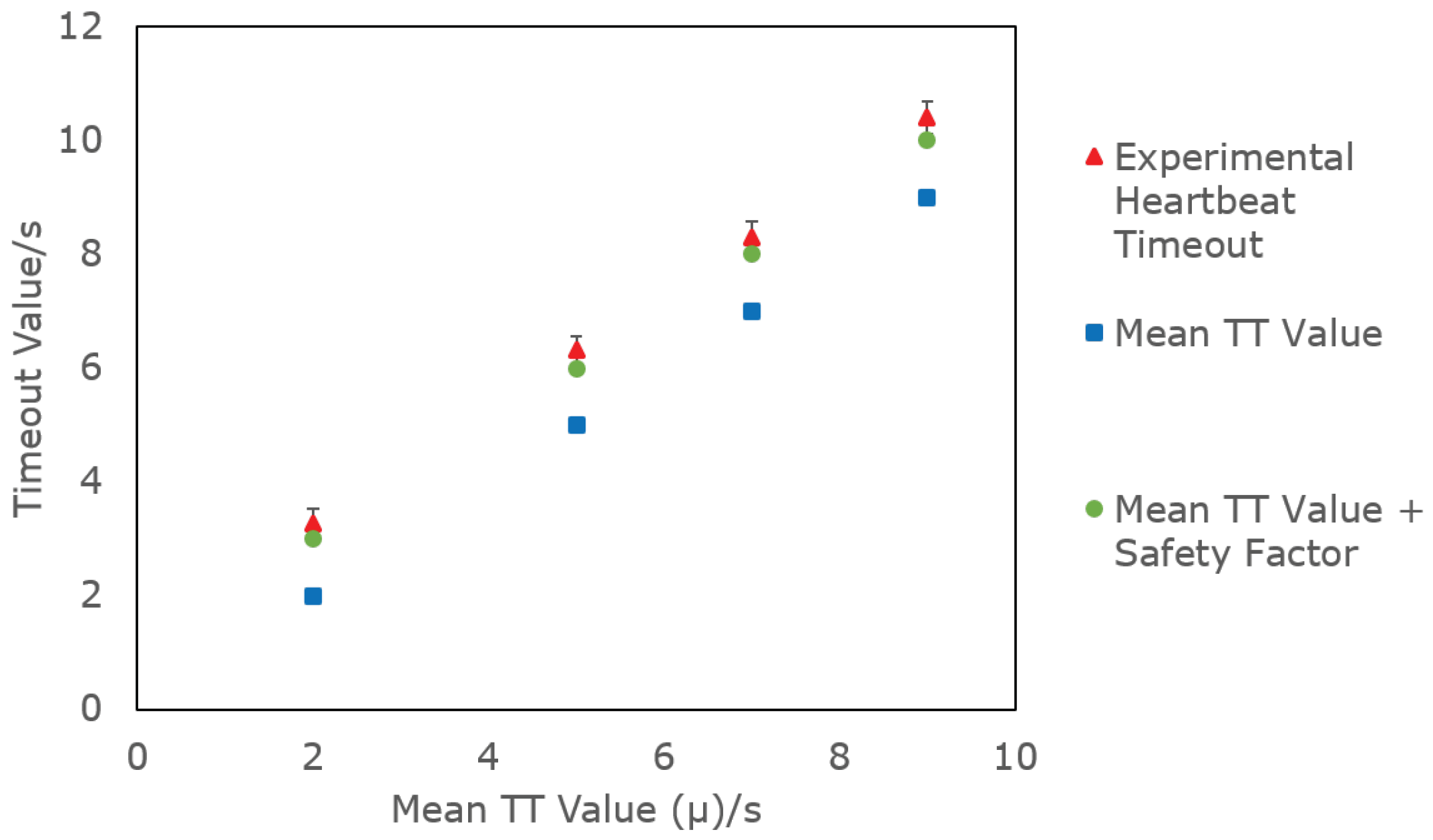
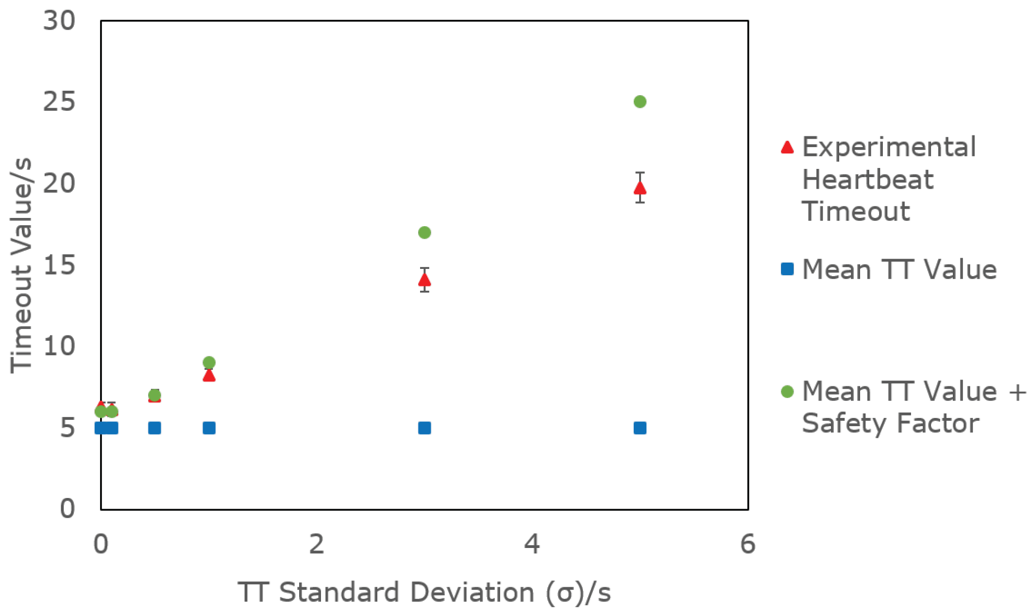
From Figure 7 and Figure 9, the experimental heartbeat timeouts at steady state follow the same trend as the theoretical values (i.e., the mean TT value with added safety factors) given by Jacobson’s algorithm. Comparing the plots of mean TT and mean TT + safety factor from Figure 9 show that the safety factor was calculated in accordance to Jacobson’s algorithm. At low values of , the clock granularity (G = 1 s) was more significant; hence the safety factor was set to be equal to G. However, when increased to a point where , the safety factor was set to . These findings proved the effectiveness of the algorithm in calculating an optimal heartbeat timeout.
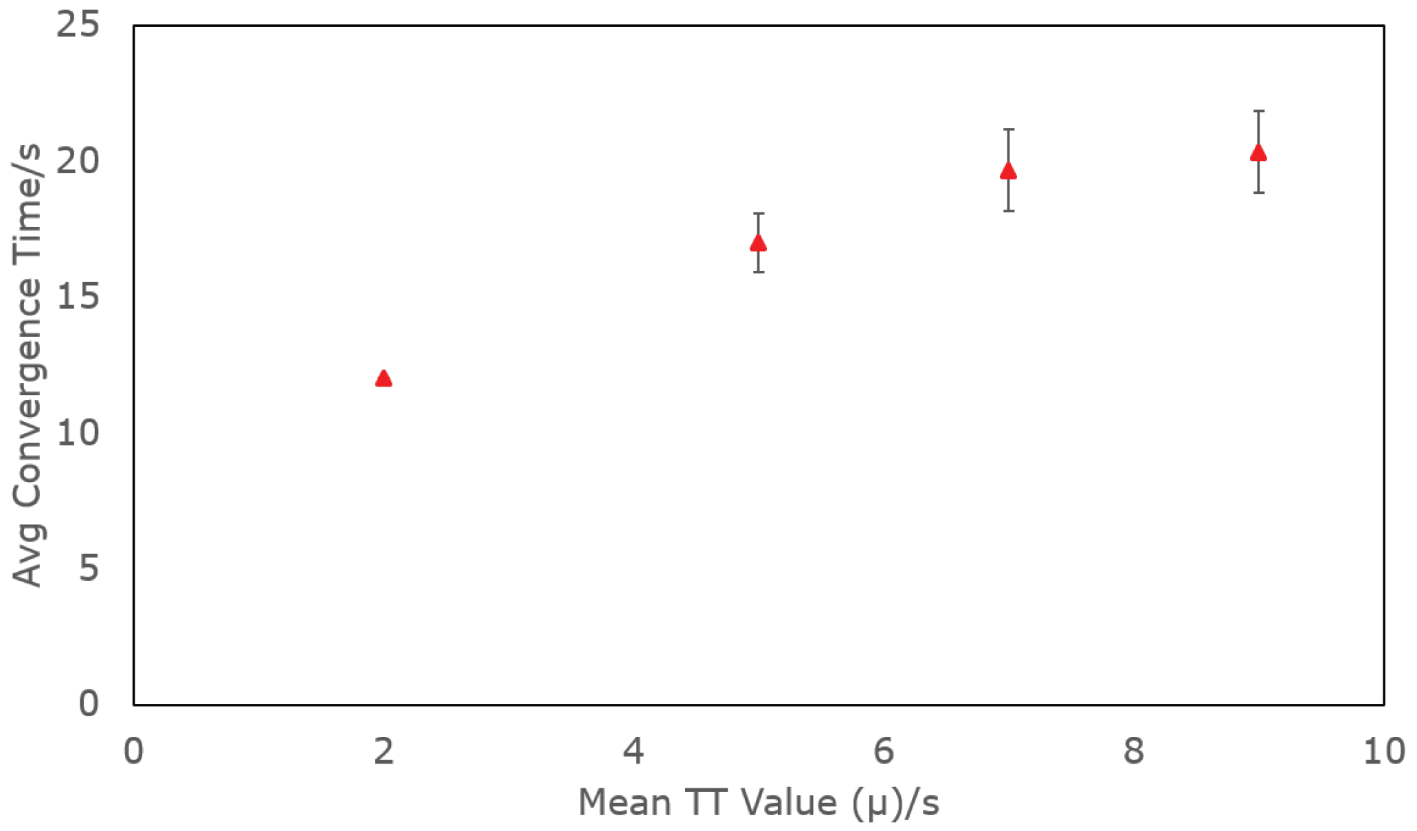
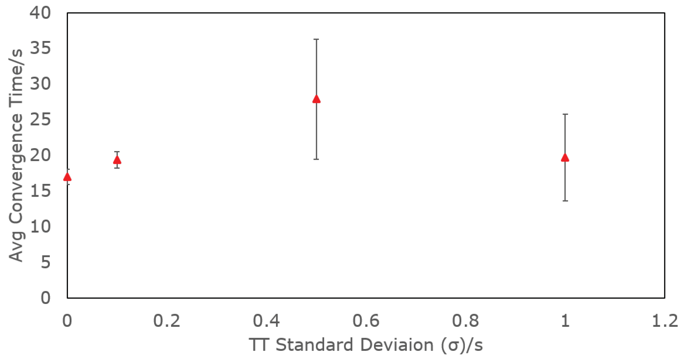
From Figure 8 and Figure 10, the convergence time increased when or increased, suggesting that the algorithm was less efficient at converging to the optimal heartbeat timeout under poor or unpredictable network connectivity. In particular, when increased beyond 1 s, the convergence behaviour transitioned from that of Figure 4 to Figure 5, resulting in an infinite convergence time. It could be deduced that there must be a threshold value for , beyond which there would be no observable convergence behaviour in the experimentally calculated heartbeat timeout. Such behaviour was due to the fact that the resulting variance would be more significant than the initial value of the experimental heartbeat timeout, meaning that the heartbeat timeout would already have begun at “steady state” and effectively have no convergence behaviour.
Unfortunately, time and resource constraints meant that the data collected was insufficient to properly model the trends in convergence behaviour; Figure 8 and Figure 10 show that this trend was positively correlated with increasing and , but it was not known whether the relationship is linear, polynomial, etc. In addition, the threshold for could not be accurately determined from the existing data. To better understand the convergence behaviour at high or unpredictable latencies, more tests should be carried out.
4.2. Experiment 3
From Figure 5, the most significant observation was that the convergence behaviour was always the same upon initialisation and during recovery. The heartbeat timeout would start at , before converging in similar fashion to the steady state value. The algorithm would always take the same time to converge, without retaining any “memory” of the previously converged value. Such a behaviour was not time-efficient, especially in situations where link switches were triggered frequently.
4.3. Suggested Improvements
The design of the link switch algorithm was based on a combination of heartbeat method and optimisations, with the heartbeat timeout calculated using a modified version of Jacobson’s algorithm. The lab tests revealed that more improvements could be made.
Firstly, the results showed that the time taken to converge to an optimal heartbeat timeout was longer under poorer and more unpredictable connectivity. It is a concern as Yonah’s drone operations would likely take place in regions with such connectivity. Further studies are needed to properly model the convergence behaviour in such an environment so as to propose improvements to the algorithm.
Second, to address the problem of recalculating the heartbeat timeout during link recovery, methods of speeding up the recovery phase should be implemented. A “memory” of the previously converged value should be stored in the system, and used as reference to speed up convergence time. For example, in the TCP protocol, fast recovery strategies are used to speed up the rate at which the network recalculates its congestion window after a retransmission [20]. Such methods could be used as inspiration to implement optimisations in the link switch and Jacobson’s algorithms to speed up the recovery phase.
Third, while the initial value of the heartbeat timeout was set to a conservative value (), it would not be enough for the edge case where the connectivity is so poor that the TT might exceed this value. In such scenarios, the ground operator would still need to know the general connectivity behaviour of the flight environment before setting a suitable value for (albeit estimating this value is much easier than estimating TT and !). However, this scenario would go against the idea of making the system easy for non-technical personnel to handle, which was the entire purpose of designing the link-switch algorithm. Improvements should be made to the way the initial heartbeat timeout is set. For example, another layer could be added to the Jacobson algorithm where the initial value of the heartbeat timeout be changed based on how often link switches were triggered (e.g., more frequent triggering of link switches could prompt the algorithm to set the initial heartbeat timeout to a higher value upon next recovery).
Fourth, the Jacobson algorithm assumes that the TT network behaviour follows a normal distribution. However, studies showed that computer networks might follow other distributions such as exponential or the heavy-tailed Pareto distribution; it could not be ruled out that UAV flight environments would be similar [22]. Research was previously carried out on optimising TCP’s RTO in such distributions, and the work could possibly be used to extend the link-switch algorithm to handle non-normal TT distributions [22].
Fifth, an assumption was made that, since the satellite link had global coverage, it could always be relied on as a final backup link and would not fail. The assumption simplified the link switch model by not having to take into account a total link failure situation. However, this assumption would not hold, in the event of hardware failure of the satellite modem. The system should be improved to detect total link failure and respond accordingly (e.g., instruct the UAV to perform an emergency landing).
Finally, testing should be performed using actual UAS. While the lab simulations provided a valuable, first pass insight into the effectiveness of the algorithm, they were too controlled and might not have taken into account factors which would otherwise arise in real-world environments. One example would be the performance of the system in adverse weather conditions, which might affect the reception of satellite and cellular networks. Real-world flight tests could not be carried out in this study due to resource constraints and restrictions due to the Covid-19 pandemic, and should be an integral part of subsequent research.
5. Conclusions
A novel link failure detection and switching algorithm was proposed for a dissimilar redundant UAV communication system, designed for long-range vaccine delivery in rural areas. The algorithm would reduce the workload of the ground operators by automatically handling link failure detection and switching. A two-layer design was proposed: A baseline layer inspired by the heartbeat method to detect both local and remote failure, and optimisations to speed up detection of local failure. A modified Jacobson’s algorithm was used to dynamically tune the heartbeat timeout during runtime, removing the need for manual tuning. Lab simulations with real hardware provided a first pass insight into the system behaviour, and found that Jacobson’s algorithm was accurate in calculating an optimal heartbeat timeout. However, more studies are needed to accurately model the behaviour at poor connectivity and further optimisations should be made to the system. Moreover, real-world flight-tests should be carried out as part of subsequent research. Compared to existing UAV communication systems, the proposed algorithm reduces operating cost, yet at the same time ensures that the downtime between link failure and switching is not excessively compromised. This feature is important for humanitarian missions, which are expected to rely on medium/high latency and metered links such as cellular and satellite. This study contributes to research and development in ensuring simple, accessible and reliable UAV communication for humanitarian purposes.
Author Contributions
Conceptualization, Y.H.L. and M.H.A.J.; methodology, Y.H.L.; software, Y.H.L.; validation, Y.H.L.; formal analysis, Y.H.L.; investigation, Y.H.L.; resources, M.H.A.J.; data curation, Y.H.L.; writing—original draft preparation, Y.H.L.; writing—review and editing, M.H.A.J.; visualization, Y.H.L.; supervision, M.H.A.J.; project administration, Y.H.L. and M.H.A.J. All authors have read and agreed to the published version of the manuscript.
Funding
This research has been supported by Yonah Pte Ltd and the National University of Singapore.
Data Availability Statement
The data presented in this study are available in https://github.com/yonahbox/Yonah_ROS_packages/tree/ogc_v2.1 (accessed on 16 April 2021)
Acknowledgments
The authors will like to express their gratitude to the co-founders of Yonah Pte Ltd.—Ong Tian Chang and Sim Zhi Min—for their supervision and logistical support for this project. Credit must be given to the the team of NUS Undergraduates attached to Yonah Pte Ltd.—Wang Huachen, Petrus Kanisius Dani, Rumesh Sundaharan, Tee Zhen Lee, Ivan Tan, Tarasvin Pan and Ding Lingke—for providing mechanical, electronics and software support to accelerate the development of this project.
Conflicts of Interest
Y.H.L. was attached to Yonah Pte Ltd. during the duration of this study.
Abbreviations
The following abbreviations are used in this manuscript:
| BVLOS | Beyond Visual Line-of-Sight |
| LTE | Long Term Evolution |
| MAVLink | Micro-Air-Vehicle Link Communication Protocol |
| ROS | Robot Operating System |
| RTT | Round Trip Time |
| SAR | Search and Rescue |
| SBD | Short Burst Data |
| SMS | Short Message Service |
| TCP | Transmission Control Protocol |
| UAS | Unmanned Aerial System |
| UAV | Unmanned Aerial Vehicle |
| TT | Trip Time |
| Mean TT value under steady state conditions | |
| TT Standard Deviation under steady state conditions | |
| Heartbeat broadcast frequency during link failure |
Appendix A. Design of Yonah’s UAV Communication System
This appendix explains the design and integration of Yonah’s UAV communication system prior to this study. An overview of the entire system is first described, before focusing on each communication link in greater detail.
Appendix A.1. Overall System Design
The diagram of the software architecture was given in Figure 1.
The ground side software was run on a consumer laptop with Ubuntu 20.04 and ROS Noetic. The laptop was connected to a RUT955 cellular router through Ethernet, and a Rockblock 9603 satellite modem via USB-serial connection. The function of the RUT955 and Rockblock 9603 will be explained in Appendices Appendix A.2, Appendix A.3 and Appendix A.4.
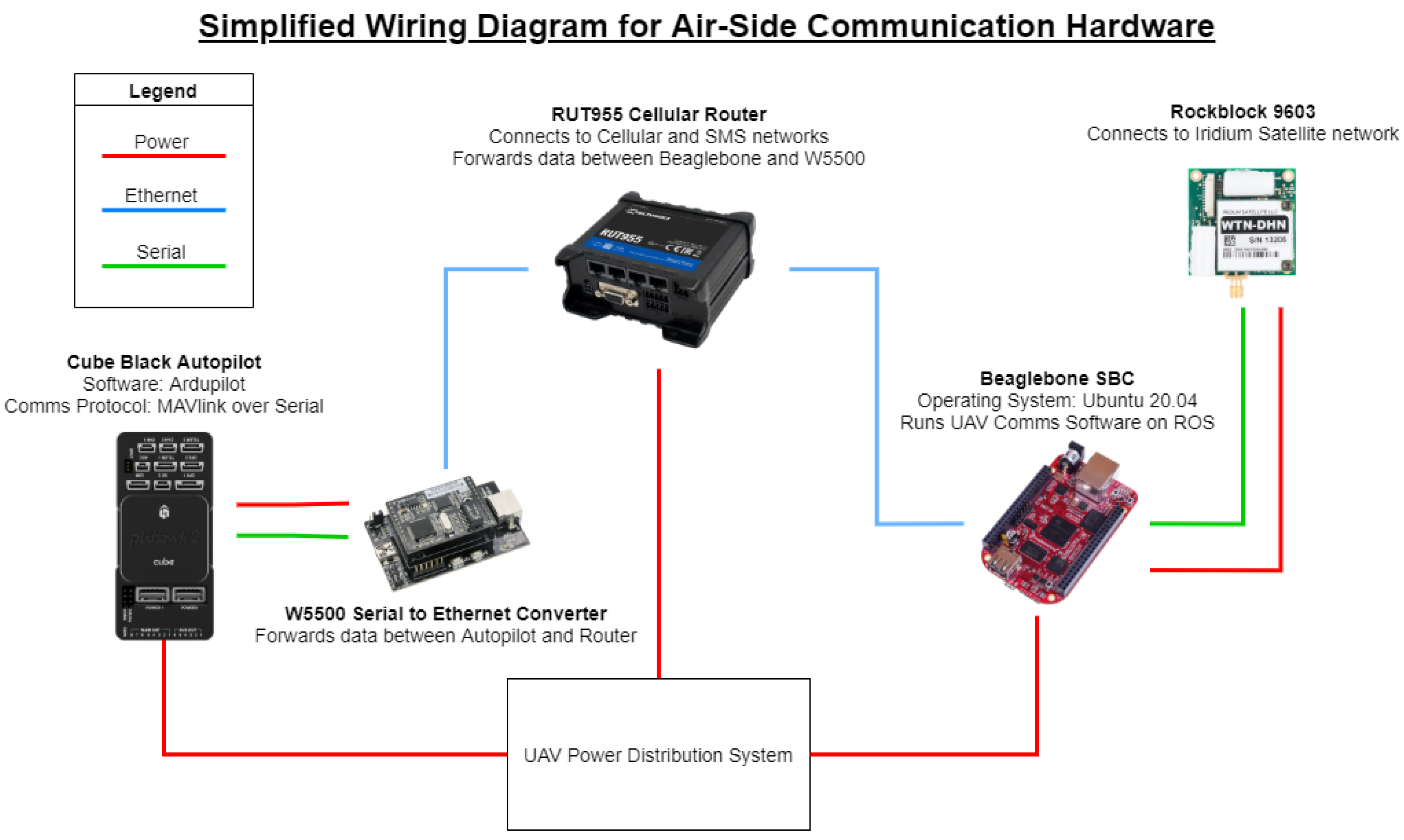
Running the air side software was more challenging. The wiring diagram for the UAV communication hardware is shown in Figure A1.
Figure A1.
Wiring Diagram for UAV Communication System (Air Side).

The software was embedded in a Beaglebone Black Industrial Single Board Computer (SBC) running Ubuntu 20.04 and ROS Noetic. It was installed on the UAV and communicated with the autopilot through Ethernet, using the RUT955 Cellular Router and a W550 Serial-to-Ethernet converter as an Ethernet bridge. The SBC was connected to the RUT955 and Rockblock 9603 similar to the ground side. The SBC effectively hosted the UAV Communication software onboard the drone, and served as a bridge between the autopilot and the communication hardware.
The custom UAV Power Distribution System was designed to distribute power to the various hardware components in accordance with their individual power requirements. The hardware presented in Figure A1 was mounted on a customised Avionics Rack installed within the drone. The design of the Power Distribution System and Avionics Rack will not be described in this paper, but are available upon request from the authors.
As mentioned in Section 1.3, Yonah’s UAS used a triple-redundant design. Dissimilar redundancy was used to provide system reliability. Each link was selected based on the following requirements:
- Simple and user-friendly for ground operators.
- Accessible in rural areas.
- Reliable communication up to 100 km.
Appendix A.2. Cellular Data Link
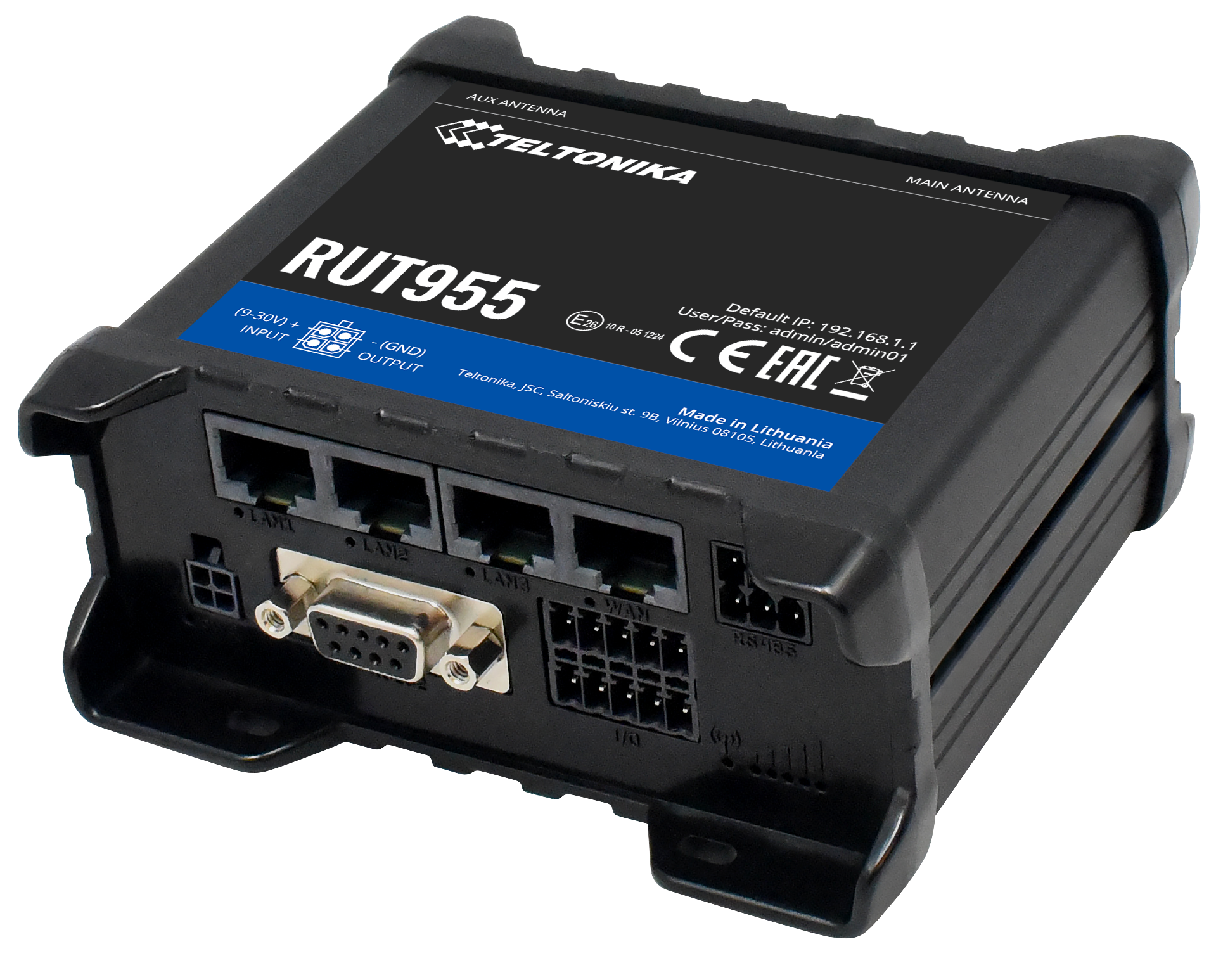
The cellular link, which operated on LTE and 3G networks, was the primary, lowest-latency link of the UAS. In order to fulfill the requirements of reliability and accessibility, the Telegram messaging platform—which is free, programmable via the open source Tdlib Application Programming Interface (API), and can send up to 100 messages per second—was used. To connect to Telegram over the Internet, a RUT955 cellular router (Figure A2) was installed on both the UAV and GCS.
Figure A2.
RUT955 Cellular Router.

The ROS Nodes handling the cellular link used the Tdlib API to convert outgoing data into Telegram messages (and vice versa for incoming data), before sending these messages through the connection provided by the RUT955. A pair of symmetrical ROS Nodes were integrated into the software of the UAV and GCS respectively.
Appendix A.3. SMS Link
The SMS link was selected due to the simplicity and accessibility of SMS. It connected to 2G networks using the RUT955 cellular router from Figure A2. As the frequency of messages sent over SMS was lower than Telegram, the link was designated as the first backup rather than the primary link.
The RUT955 provided an API that allowed applications to send or receive messages through SMS. The ROS Nodes handling the SMS link used this API to convert outgoing data into SMS messages, and vice versa.
Appendix A.4. Satellite Link
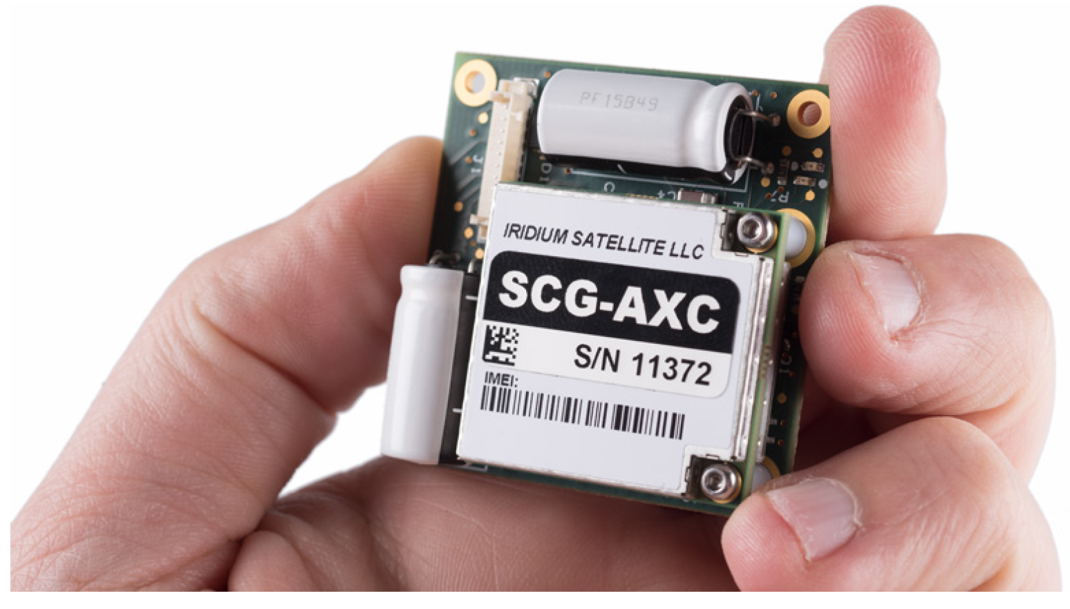
The satellite link was to be the final backup upon total loss of cellular coverage; thus a satellite network with reliable coverage was essential. The Rockblock 9603 modems (Figure A3) were selected as they used Iridium’s global satellite constellation to communicate via Iridium SBD protocol. They were also one of the few low-cost satellite modems on the market, and could be handled using simple AT commands instead of closed-sourced APIs; hence fulfilling the requirements of simplicity and accessibility. Two Rockblock 9603 modems were installed; one on the UAV and another on the GCS.
Figure A3.
Rockblock 9603 Satellite Modem.

The ROS Nodes handling the satellite link compressed outgoing data into text messages before using AT commands to instruct the Rockblock 9603 to send the messages, and vice versa.
Appendix B. Guide to Running Lab Simulations
This Appendix provides a simplified guide for any researcher who needs to replicate the results in this study or conduct further research in this area. For more detailed instructions, refer to the documentation for Yonah’s Communication System: https://github.com/yonahbox/Yonah_ROS_packages/wiki (acccessed on 16 April 2021)
Appendix B.1. Software Details
The source code for Yonah’s communication software is available on Github: https://github.com/yonahbox/Yonah_ROS_packages/tree/ogc_v2.1 (acccessed on 16 April 2021). The software consisted of an ROS ecosystem that was briefly introduced in Figure 1. The link-switch algorithm is run using an ROS Node called “switcher”. This node is located in the “ogc” ROS workspace and the “despatcher” ROS package. The modified Jacobson algorithm is called by the “switcher” node, and is located in a module called ”dynamic delay”.
The code for high latency simulation is also found in the “switcher” ROS node, and can be activated or deactivated using a toggle value.
Appendix B.2. Required Materials
The required hardware to run Yonah’s communication system is documented in https://github.com/yonahbox/Yonah_ROS_packages/wiki/Required-Hardware (acccessed on 16 April 2021). In particular, the following should be setup on the air side for a lab simulation, as given in Figure A1:
- 1 × RUT955 cellular router with SIM card inserted.
- 1 × Rockblock 9603 satellite modem.
- 1 × Beaglebone Black Industrial SBC.
- 1 × CubeBlack autopilot running Arduplane 3.9.8 firmware.
- 1 × W5500 Serial to Ethernet Converter + Carrier Board.
- Power source for all the above-mentioned hardware.
The source code for the communication software can be downloaded from Github as mentioned in Appendix B.1, and should be hosted in the Beaglebone Black. The Beaglebone should be running Ubuntu 20.04 OS with ROS Noetic. The instructions for setting up the software is documented on Github: https://github.com/yonahbox/Yonah_ROS_packages/wiki/Software-Installation (acccessed on 16 April 2021)
The wiring diagram for the air side hardware is shown in Figure A1. Note that in Yonah’s drones, a custom power distribution system was designed to meet the differing power requirements of each hardware. However, using this custom distribution system is not mandatory for lab simulations (e.g., the RUT955 can also be powered from a wall socket).
The ground side is managed by a laptop running Ubuntu 20.04 OS. It should be connected to a RUT955 router over Ethernet/Wifi, and a Rockblock 9603 over USB. The same software should be run on the ground side laptop; it can be downloaded and installed using the documentation mentioned previously.
Finally, a cloud server is required; the server’s purpose was to provide a user-friendly way for the UAV and GCS to recognise each other. The server should also be running Ubuntu 20.04 OS. The setup procedures for the server are documented here: https://github.com/yonahbox/Yonah_ROS_packages/wiki/Software-Installation#server-side-installation (acccessed on 16 April 2021). For the lab simulation, only the sections “Initial Setup” and “Initial Setup of Identifiers System” need to be followed.
Appendix B.3. Experimental Preconfiguring
Prior to launching the software on either the air or ground side, the user should set the parameters that control the behaviour of the simulations. These parameters are found in the ROS “Switcher” node:
- The “SIM” variable activates or deactivates the high latency simulator. Set it to 1 to activate the simulator.
- The “mean” variable is the mean delay added to the system. This delay is added to the time interval between each heartbeat to generate the overall for the Trip Time.
- The “stdev” variable controls the TT value directly.
The user should modify these values on both the air and ground side, and should preferably set the values to be equal across both sides. The software on the air side can be accessed through a ssh connection into the Beaglebone.
In addition, the user may opt to modify the time interval between each heartbeat broadcast on the cellular link. This is another method to increase TT . This can be done by accessing the ROS launch files on both sides. The files are located in the “launch” folder on the Github repository. The air launch file is labelled “ogc airtest” while the ground launch file is labelled ”ogc groundtest”. Two critical parameters control the time interval of the cellular link:
- Interval 1. This is the time interval between each heartbeat on the cellular link when the link is active.
- Interval 2. This is the time interval between each heartbeat on the cellular link when the link has failed.
Finally, the user is advised to simplify the flow of the lab tests by disabling ROS nodes that are non-essential to the tests. These include the “sms”, “sbd”, “statustext”, “rff” and “feedback timeout” nodes on both air and ground sides.
Appendix B.4. Experimental Procedures
After making all pre-launch configurations, the user can launch the “ogc groundtest” launch file on the ground side to start the communication system. He/she should then use the provided graphical interface to select the ID of the “aircraft” that the GCS should be communicating with, so that a signal can be sent to the air side. The air side would automatically start its software upon bootup and wait for the necessary signals from the ground side before broadcasting heartbeats.
During a test run, if the “SIM” toggle is active, the experimental heartbeat timeout and true TT values will be logged to CSV files, which are located in the home directories of the GCS (for ground side) and Beaglebone (for air side). These CSV files can be used to plot and analyse the test runs. In addition, the heartbeat timeout and TT values are also printed onto the terminal for real-time monitoring purposes.
In between test runs, in order to modify and , the user should stop the software on both sides, modify the “mean” and “stdev” variables mentioned previously, before rebooting the system on both sides (this can be done either through a hard reboot or caling a systemd restart).
For Experiment 3, the user should manually disconnect and reconnect the Wifi on the ground side to simulate link failure and recovery.
References
- Gilman, D.; Easton, M.; Gelsdorf, K.; Strohmeyer, H. Unmanned Aerial Vehicles in Humanitarian Response; Technical Report; United Nations Office for the Coordination of Humanitarian Affairs, Policy Development and Studies Branch: New York, NY, USA, 2014. [Google Scholar]
- Dirks, W.; Guirao, O.L.; Di Carlo, S. Evaluation of the Business Cases for Cargo Drones in Humanitarian Action; Technical Report; Medecins Sans Frontiers: Tokyo, Japan, 2017. [Google Scholar]
- Roberts, J.; Frousheger, D.; Williams, B.; Campbell, D.; Walker, R. How the UAV Challenge Outback Rescue was finally won. IEEE Robot. Autom. Mag. 2015, 23, 54–62. [Google Scholar] [CrossRef]
- Yonah. Connecting Rural Healthcare Systems. 2020. Available online: https://www.yonah.sg/ (accessed on 11 March 2021).
- Volkert, A.; Hackbarth, H.; Joonas Lieb, T.; Kern, S. Flight Tests of Ranges and Latencies of a Threefold Redundant C2 Multi-Link Solution for Small Drones in VLL Airspace. In Proceedings of the 2019 Integrated Communications, Navigation and Surveillance Conference (ICNS), Herndon, VA, USA, 9–11 April 2019. [Google Scholar] [CrossRef] [Green Version]
- Austin, R. Unmanned Aircraft Systems: UAV Design, Development and Deployment; John Wiley and Sons Ltd.: Chichester, UK, 2010. [Google Scholar]
- Li, B.; Jiang, Y.; Sun, J.; Cai, L.; Wen, C.Y. Development and Testing of a Two UAV Communication Relay System. Sensors 2016, 16, 1696. [Google Scholar] [CrossRef] [PubMed]
- Gorczak, P.; Bektas, C.; Kurtz, F.; Lübcke, T.; Wietfeld, C. Robust Cellular Communications for Unmanned Aerial Vehicles in Maritime Search and Rescue. In Proceedings of the 2019 IEEE International Symposium on Safety, Security, and Rescue Robotics (SSRR), Würzburg, Germany, 2–4 September 2019. [Google Scholar]
- Güldenring, J.; Koring, L.; Gorczak, P.; Wietfeld, C. Heterogeneous Multilink Aggregation for Reliable UAV Communication in Maritime Search and Rescue Missions. In Proceedings of the Sixth International Workshop on ICT Systems for Public Protection and Risk Reduction, Barcelona, Spain, 21–23 October 2019; pp. 215–220. [Google Scholar]
- Güldenring, J.; Gorczak, P.; Eckermann, F.; Patchou, M.; Tiemann, J.; Kurtz, F.; Wietfeld, C. Reliable Long-Range Multi-Link Communication for Unmanned Search and Rescue Aircraft Systems in Beyond Visual Line of Sight Operation. Drones 2020, 4, 16. [Google Scholar] [CrossRef]
- Kerczewski, R.J.; Meza, M.; Gupta, O. Application of the Iridium Satellite System to Aeronautical Communications; Technical Report; NASA Technical Reports Server: Houston, TX, USA, 2008. [Google Scholar]
- Downer, J. When Failure is an Option: Redundancy, Reliability and Regulation in Complex Technical Systems; LSE Research Online Documents on Economics 36537; London School of Economics and Political Science, LSE Library: London, UK, 2009. [Google Scholar]
- Geraci, G.; Garcia-Rodriguez, A.; Giodarno, L.G.; Lopez-Perez, D.; Bjornson, E. Understanding UAV Cellular Communications: From Existing Networks to Massive MIMO. Inst. Electr. Electron. Eng. IEEE Access 2018, 6, 67853–67865. [Google Scholar] [CrossRef]
- Hosseini, N.; Jamal, H.; Haque, J.; Magesacher, T.; Matolak, D.W. UAV Command and Control, Navigation and Surveillance: A Review of Potential 5G and Satellite Systems. In Proceedings of the 2019 IEEE Aerospace Conference, Big Sky, MT, USA, 2–9 March 2019; pp. 1–10. [Google Scholar] [CrossRef] [Green Version]
- Seven, R. Rockblock 9603. 2020. Available online: https://www.rock7.com/products/rockblock-9603-compact-plug-play-satellite-transmitter (accessed on 11 March 2021).
- Zhou, Y.; Jun, L.; Lamont, L.; Rabbath, C.A. A Markov-Based Packet Dropout Model for UAV Wireless Communications. J. Commun. 2012, 7, 418–425. [Google Scholar] [CrossRef]
- Zhao, H.; Wang, H.; Wu, W.; Wei, J. Deployment Algorithms for UAV Airborne Networks Toward On-Demand Coverage. IEEE J. Sel. Areas Commun. 2018, 36, 2015–2031. [Google Scholar] [CrossRef]
- Kleinberg, J.; Sandler, M.; Slivkins, A. Network Failure Detection and Graph Connectivity. In Proceedings of the Fifteenth Annual ACM-SIAM Symposium on Discrete Algorithms, Baltimore, MD, USA, 12–14 January 2013; Society for Industrial and Applied Mathematics: Philadelphia, PA, USA, 2003; pp. 76–85. [Google Scholar]
- MAVlink. MAVlink Source Code (Github). 2021. Available online: https://github.com/mavlink/mavlink (accessed on 11 March 2021).
- Jacobson, V.; Karels, M.J. Congestion Avoidance and Control. In Proceedings of the SIGCOMM ’88, Stanford, CA, USA, 16–18 August 1988. [Google Scholar]
- Paxson, V.; Allman, M.; Chu, J.; Sargent, M. RFC6298: Computing TCP’s Retransmission Timer. 2011. Available online: https://tools.ietf.org/html/rfc6298 (accessed on 11 March 2021).
- Kesselman, A.; Mansour, Y. Optimizing TCP Retransmission Timeout. In Proceedings of the 4th International Conference on Networking, Reunion Island, France, 17–21 April 2005; Volume 3421, pp. 133–140. [Google Scholar] [CrossRef] [Green Version]
Short Biography of Authors
 | Yan Han Lau is a final-year Mechanical Engineering undergraduate at the National University of Singapore (NUS), specialising in Aeronautical Engineering and Unmanned Aviation Systems. During his undergraduate studies, he was attached to Yonah Pte Ltd as a Guidance, Navigation and Control Engineer. His work included assisting in the integration and flight testing of Yonah’s UAV avionics, tuning of the multirotor PID controller, and design of the long-range, dissimilar redundant UAV Communication System. His contributions to the research and development of Yonah’s avionics capabilities led him to be awarded the NUS Outstanding Undergraduate Research Prize in 2019. |
 | Marcelo H Ang, Jr. received the B.Sc. degrees (Cum Laude) in Mechanical Engineering and Industrial Management Engineering from the De La Salle University, Manila, Philippines, in 1981; the M.Sc. degree in Mechanical Engineering from the University of Hawaii at Manoa, Honolulu, Hawaii, in 1985; and the M.Sc. and Ph.D. degrees in Electrical Engineering from the University of Rochester, Rochester, New York, in 1986 and 1988, respectively. His work experience includes heading the Technical Training Division of Intel’s Assembly and Test Facility in the Philippines, research positions at the East West Center in Hawaii and at the Massachusetts Institute of Technology, and a faculty position as an Assistant Professor of Electrical Engineering at the University of Rochester, New York. In 1989, Dr. Ang joined the Department of Mechanical Engineering of the National University of Singapore, where he is currently a Professor. He is also the Acting Director of the Advanced Robotics Centre. His research interests span the areas of robotics, mechatronics, and applications of intelligent systems methodologies. He teaches both at the graduate and undergraduate levels in the following areas: robotics; creativity and innovation, and Engineering Mathematics. He is also active in consulting work in robotics and intelligent systems. In addition to academic and research activities, he is actively involved in the Singapore Robotic Games as its founding chairman and the World Robot Olympiad as a member of the Advisory Council. |
Figure 1.
Overall Software Architecture Diagram of Yonah UAV Communication System.

Figure 2.
State Diagram of Proposed Link Switch Algorithm.

Figure 3.
Experimental setup photo, with ground side on left and air side on right.

Figure 4.
Sample plot of a test run, with = 5 s, = 0.3 s.

Figure 5.
Sample plot of a test run, with = 5 s, = 3 s.

Figure 6.
Sample plot of a test run in Experiment 3, with = 5 s, = 0.1 s.

Figure 7.
Plot of experimental steady state heartbeat timeout against , with constant = 0 s. Plot is superimposed with the mean TT value (), and + safety factor given by Jacobson’s algorithm.
Figure 7.
Plot of experimental steady state heartbeat timeout against , with constant = 0 s. Plot is superimposed with the mean TT value (), and + safety factor given by Jacobson’s algorithm.

Figure 8.
Plot of average convergence time for heartbeat timeout value against , with constant = 0 s.
Figure 8.
Plot of average convergence time for heartbeat timeout value against , with constant = 0 s.

Figure 9.
Plot of experimental steady state heartbeat timeout against , with constant = 0 s. Plot is superimposed with the mean TT value , and + safety factor given by Jacobson’s algorithm.
Figure 9.
Plot of experimental steady state heartbeat timeout against , with constant = 0 s. Plot is superimposed with the mean TT value , and + safety factor given by Jacobson’s algorithm.

Figure 10.
Plot of average convergence time for heartbeat timeout value against , with constant = 5 s.
Figure 10.
Plot of average convergence time for heartbeat timeout value against , with constant = 5 s.


Table 1.
List of selected protocols for Yonah UAV Communication System.
| Link | Protocol | Purpose |
|---|---|---|
| 1 | Cellular Data | Primary link in areas with Long Term Evolution (LTE)/3G networks. |
| 2 | SMS | First backup link in areas without LTE/3G but with 2G coverage |
| 3 | Satellite | Final backup Link when there is zero cellular coverage. Communicates through Iridium’s global satellite network |
Publisher’s Note: MDPI stays neutral with regard to jurisdictional claims in published maps and institutional affiliations. |
© 2021 by the authors. Licensee MDPI, Basel, Switzerland. This article is an open access article distributed under the terms and conditions of the Creative Commons Attribution (CC BY) license (https://creativecommons.org/licenses/by/4.0/).
Share and Cite
MDPI and ACS Style
Lau, Y.H.; Ang, M.H., Jr. A Novel Link Failure Detection and Switching Algorithm for Dissimilar Redundant UAV Communication. Drones 2021, 5, 48. https://0-doi-org.brum.beds.ac.uk/10.3390/drones5020048
AMA Style
Lau YH, Ang MH Jr. A Novel Link Failure Detection and Switching Algorithm for Dissimilar Redundant UAV Communication. Drones. 2021; 5(2):48. https://0-doi-org.brum.beds.ac.uk/10.3390/drones5020048
Chicago/Turabian StyleLau, Yan Han, and Marcelo H. Ang, Jr. 2021. "A Novel Link Failure Detection and Switching Algorithm for Dissimilar Redundant UAV Communication" Drones 5, no. 2: 48. https://0-doi-org.brum.beds.ac.uk/10.3390/drones5020048