Article

UAV4PE: An Open-Source Framework to Plan UAV Autonomous Missions for Planetary Exploration

1
School of Electrical Engineering and Robotics, Queensland University of Technology (QUT), 2 George St., Brisbane City, QLD 4000, Australia
2
Securing Antartica’s Environmental Future (SAEF), Monash University, Clayton Campus, Level 1, 17 College Walk (Building 31), Melbourne, VIC 3800, Australia
3
School of Earth and Atmospheric Sciences, Queensland University of Technology (QUT), 2 George St., Brisbane City, QLD 4000, Australia
*
Author to whom correspondence should be addressed.
Submission received: 11 November 2022 / Revised: 28 November 2022 / Accepted: 28 November 2022 / Published: 2 December 2022

Abstract

:
Autonomous Unmanned Aerial Vehicles (UAV) for planetary exploration missions require increased onboard mission-planning and decision-making capabilities to access full operational potential in remote environments (e.g., Antarctica, Mars or Titan). However, the uncertainty introduced by the environment and the limitation of available sensors has presented challenges for planning such missions. Partially Observable Markov Decision Processes (POMDPs) are commonly used to enable decision-making and mission-planning processes that account for environmental, perceptional (extrinsic) and actuation (intrinsics) uncertainty. Here, we propose the UAV4PE framework, a testing framework for autonomous UAV missions using POMDP formulations. This framework integrates modular components for simulation, emulation, UAV guidance, navigation and mission planning. State-of-the-art tools such as python, C++, ROS, PX4 and JuliaPOMDP are employed by the framework, and we used python data-science libraries for the analysis of the experimental results. The source code and the experiment data are included in the UAV4PE framework. The POMDP formulation proposed here was able to plan and command a UAV-based planetary exploration mission in simulation, emulation and real-world experiments. The experiments evaluated key indicators such as the mission success rate, the surface area explored and the number of commands (actions) executed. We also discuss future work aimed at improving the UAV4PE framework, and the autonomous UAV mission planning formulation for planetary exploration.

1. Introduction

The use of unmanned aerial vehicles (UAVs), or drones, continues to spread across diverse fields such as ecology, geology, environmental protection and planetary exploration [1,2,3,4,5]. Planetary exploration is also an area of growth, with the Mars Helicopter Ingenuity (see Figure 1), exceeding remarkable performance goals. At the time of writing, Ingenuity has completed over 34 successful flights [6], providing key foundational knowledge in using UAVs for planetary exploration.
Originally developed as a technology demonstration, Ingenuity has endured much longer than baseline and increased the efficiency of the National Aeronautics and Space Administration (NASA)’s flagship Perseverance rover mission. Perseverance was designed to study habitability and biosignature preservation in rocks in Mars’ Jezero crater, to drill core samples from them, and prepare the samples to be returned to Earth by future missions [7,8,9]. Ingenuity’s remarkable performance in scouting locations for Perseverance’s main mission gave NASA the confidence to include two Ingenuity-like helicopters to support the Mars Sample Return (MSR) program in the years ahead [10], further consolidating the importance of UAVs for planetary exploration tasks (See Figure 2).
One important objective of mission planning for Mars exploration is the search for biosignatures. Biosignatures are morphological, mineral, chemical, or isotopic traces of organisms preserved in the rock record [11]. UAVs can help accelerate the search for biosignatures at different scales, with textural biosignatures being the most promising for near-future UAV-based applications [12]. However, the literature on autonomous UAVs capable of making real-time decisions towards the detection of biosignatures is scarce [5].
The need for higher levels of UAV autonomy for planetary exploration is increasing, especially with the proliferation of more UAV missions in complex scenarios such as NASA’s Dragonfly mission to Titan, with over 2 hours of communication delay. Tasks such as autonomous waypoint surveying or navigation strategies that preserve safety margins have the potential to accelerate the deployment of UAVs for planetary exploration scenarios. But mission-planning and navigation strategies for remote planetary exploration is an emerging field of research, with limited availability of frameworks with which to perform studies.
Ingenuity validated the value and significance of UAV platforms for planetary exploration missions. The helicopter’s capability to accelerate planetary exploration was demonstrated after moving from a technology demonstration phase to an operational phase [13,14]. NASA Scientists reported multiple benefits of having the Ingenuity helicopter available to them, including the capability to acquire contextual data in the area surrounding the rover’s workspace, which is critical to the interpretation of the geological features studied in each location visited by the wheeled rover [15].
Scouting further afield is the main application of Ingenuity, and these scouting missions are strictly timed and overseen using state machines and waypoints [15]. Ingenuity has flight-level autonomy and can execute a mission autonomously with close monitoring from Earth. In this scenario, the mission planners are humans on Earth that pick the waypoints and commands that Ingenuity will execute autonomously, which is necessary due to the long latency associated with communications between Earth and Mars (over 7 min).
Future UAV missions may be designed to scout or assist a Mars rover in different ways, such as localisation enhancement by context images [16], target identification, and sample collection [10]. Other UAV missions will aim to conduct scientific experiments without a wheeled companion, for example, NASA’s Dragonfly mission to Titan [9]. All such UAV applications will require successful autonomous mission planning, take-off, navigation, and landing.
The science yield of UAV missions such as Dragonfly can be increased by implementing uncertainty-tolerant methods to deal with environmental and internal system uncertainty involved in UAV mission planning. Several techniques to deal with mission planning have been proposed and are summarised in [17]. However, complete UAV mission planning implementations for planetary exploration are scarce, particularly those focused on uncertainties. Additionally, the authors are not aware of implementations of tools to test, validate and benchmark UAV autonomous mission planning formulations for planetary exploration.

1.1. UAV Autonomous Mission Planning for Planetary Exploration

Through the advancement of autonomous mission planning for UAVs, we aim to leverage the capabilities of UAVs and onboard sensors to accomplish more prolonged and more complex missions. A wide range of applications, such as broader-scale terrain exploration and more-targeted, faster and lower-cost data acquisition, are some of the main prospects. Previous studies have focused on techniques to improve autonomy at different levels in multiple areas such as the overall mission architecture [17,18,19], navigation [20,21], target identification [22,23], and flight [2,8]. Also of relevance are techniques developed for mission planning and navigation in Global Positioning System (GPS)-denied environments [24,25,26], as well as the use of Partially Observable Markov Decision Process (POMDP) [27].
POMDP formulations help with decision-making under uncertainty in the system behaviour (actions) and the environment (observations). UAV navigation [28] has benefited from POMDP approaches. However, mission planning can also be addressed with this approach [29]. One of the main challenges of using POMDP techniques is the computational resources required to generate an optimal solution that can be used online. To address this problem, online solvers have been developed since the introduction of the method by Kaelbling et al. [27] in 1998. Since then, POMDP has shown to be a robust approach for modelling a system when there is uncertainty in the actions and observations [25]. Another important challenge of using POMDP in real-world applications is the development of solutions (called Policies) that adopt safe and conservative behaviours. The trade-off between the exploration of actions and exploitation of rewards demands significant attention due to its implications on the safe operation of a system [30].
Our previous work formulated a planetary exploration mission planning problem using POMDP [31]. The proposed formulation was initially implemented only by simulation in [24]. The work presented in this paper extends and improves the previous implementation by introducing a realistic simulation scenario using Gazebo (http://gazebosim.org/ (accessed on 10 November 2022)) and deployment on a real platform using the Robotic Operating System (ROS) (https://www.ros.org/ (accessed on 10 November 2022)) and PX4 Autopilot (https://px4.io/ (accessed on 10 November 2022)). The POMDP problem formulation was also simplified, and further tests of the formulation parameters are available. To address the paucity of widely available open-source frameworks to test and experiment with different mission-planning and navigation strategy configurations, we present here UAV4PE, an open-source framework that can be modified and extended. The proposed framework provides an option to abstract the complexity of the UAV systems and simulation environments, combining efforts to consolidate and sustain a UAV planetary exploration framework that closes the gap between simulation, emulation and the real world.

1.2. Frameworks for UAV Autonomous Planetary Exploration

Multiple frameworks are proposed in the literature for relevant applications in the planetary exploration domain. Vanegas et al. [20] presented a framework for UAV navigation in GPS-Denied environments, where a POMDP-based probabilistic motion planning code is proposed and validated in simulation and with real experiments. Walker et al. [32] proposed a framework that uses multiple UAV exploration for target-finding in GPS-denied and partially observable environments. This framework focused on simulation and modelling the exploration planning problem as a decentralised multi-agent graph search solved using a modern POMDP solver. Sandino et al. [23] introduced a framework for navigation and object detection in cluttered indoor environments, exposing the results in simulated and real-world scenarios.
F-Prime (https://github.com/nasa/fprime (accessed on 10 November 2022)) is the current open-source firmware used in Ingenuity [33]. This framework facilitates the implementation of modular components, which are designed to be compact, reusable and portable, and capable of being compiled and executed in diverse hardware architectures, including ARM, X86, and others. The F-Prime framework also facilitates abstraction from the operative system, providing options for dealing with threads, synchronization, files, and time. The F-Prime firmware is implemented in C++, which places it close to the hardware resources, facilitating efficient implementations and deployments on final hardware, despite bearing complex and often slower development and testing procedures.
Maxim et al. [34] presented the POMDP.jl framework for sequential decision-making under uncertainty. This framework uses the Julia (https://julialang.org/ (accessed on 10 November 2022)) programming language, which is growing in popularity due to its fast, composable, general, dynamic, reproducible and open-source philosophy. POMDP.jl aims to be a common programming vocabulary for expressing problems as MDPs and POMDP, writing solver software, and running simulations efficiently (https://github.com/JuliaPOMDP/POMDPs.jl (accessed on 10 November 2022)). Klimenko et al. [35] prosed TAPIR (https://github.com/rdl-algorithm/tapir (accessed on 10 November 2022)), a software toolkit for approximating and adapting POMDP solutions online [35]. This solver has been widely used for online motion planning and target finding. It also includes standard benchmark tests, including rock sampling, tag, homecare and others, that serve as templates to be extended. However, the above-mentioned frameworks fail to address the need for benchmarks and frameworks to understand UAV autonomous mission planning for planetary exploration scenarios.

2. Background

The essential tools on which the UAV4PE framework rely are introduced and explained in this section, including ROS, the UAV Flight stack used, and the POMDP.jl library.

2.1. ROS

The Robot Operating System (ROS) was chosen as the meta-operating system for the UAV4PE  Framework. ROS provides access to hardware abstractions, low-level device control, packages, nodes and communication management. ROS also offers standard and well know interfaces for the cameras, operating systems, and flight controller (Autopilot) systems used in this work. Note that each version of ROS is matched with a version of Ubuntu; in this work, we use ROS Noetic version, which was installed in Ubuntu Mate 20.04. Ubuntu MATE was installed in a Raspberry Pi 4 model B, using a microSD card. This selection was performed based on multiple years of experience with previous embedded onboard computers and versions of ROS and Ubuntu.
ROS documentation is extensive and detailed; this section will introduce the main key elements to clarify the architecture used in the UAV4PE framework. Further documentation and tutorials about ROS can be extended on ROS’s official websites (https://wiki.ros.org/ (accessed on 1 December 2022)).
The ROS concepts of packages and nodes are essential for the UAV4PE Framework. These concepts provide modularity and interoperability across the framework and its components. The framework philosophy separates simulation, emulation, mission planning, navigation, vision, experiments, sensing, and hardware scopes as the main packages. Each package can include a set of nodes running a modular task programmed in Python or C++. Additionally, each package is set as an independent code repository, allowing individual module changes to be tracked independently. This folder structure follows the ROS package architecture. Each package can contain various subfolders for source files or scripts known as nodes, ROS launch files, models, custom ROS message type definitions and configurations.
The executable scripts within the packages are called Nodes and benefit from the ROS communication backend following the subscriber/publisher philosophy. Nodes can publish messages to information channels called Topics in the ROS communication backend; other nodes can access these messages when subscribing to topics. Note that each node can subscribe to and publish various topics and message types.

2.2. UAV Flight Stack

The UAV is controlled by a Pixracer flight controller module using PX4, running the firmware version FMUv4 1.11.3. The PX4 autopilot presents multiple benefits to the framework. It provides a highly customisable flight controller stack, compatible with standard UAV communication interfaces such as MavLink (https://mavlink.io/en/ (accessed on 10 November 2022)). PX4 firmware also supports a wide range of flight controllers and sensor integrations. It can also be integrated with tools such as QGroundControl (https://docs.qgroundcontrol.com/master/en/getting_started/quick_start.html (accessed on 10 November 2022)), which is also open source and facilitates the visualisation of telemetry information, images, parameter configuration, and sensor calibration; and is available in most operative systems, including Android and iOS. The PX4-based autopilot is commanded using its offboard functionality, where a companion computer is connected through serial communication.
In this work, we also use the Queensland University of Technology Aerospace System (QUTAS) GitHub (https://github.com/qutas (accessed on 10 November 2022)), which hosts a collection of open-sourced projects. This work uses multiple QUTAS projects to control the small UAV platform utilised in real-world experiments. It also provides tools to simulate UAVs, providing quick testing in virtual cost-free environments with sufficient proximity to real-world results.

2.3. POMDPs and the POMDP.jl Library

A POMDP is defined by the tuple S , A , O , T , Z , R , b 0 , γ , where S , A , O are a finite set of UAV states, actions, and observations, respectively [36]. Whenever the agent in POMDP theory or UAV in this case, takes an action a A from a state s S , the transition probability to a new state s S is defined by a transition function T ( s , a , s ) = P ( s s , a ) .
With a taken action a A , the UAV receives an observation o O encoded by the observation function Z ( s , a , o ) = P o s , a . Every decision chain is then costed with a reward r, calculated using the reward function R ( a , s ) . Considering that data gathering by UAV systems is imperfect, partial observability about the state of the UAV itself is always present in real-world applications. As a result, a POMDP uses probability distributions over the system states to model the uncertainty of its observed states. This modelling is denominated the belief b ( H ) = P [ s 1 H ] , , P [ s n H ] , where H is the history of actions, observations and rewards the UAV has accumulated until a time step t, or H = a 0 , o 1 , r 1 , , a t 1 , o t , r t . The planning policy π of the UAV is represented by mapping belief states to actions π : b A . The POMDP formulation solution is the optimal policy π * , calculated as follows:
π * : = arg max π E t = 0 γ t R S t , π b t ,
where γ [ 0 , 1 ] is the discount factor and defines the relative importance of immediate rewards compared to long-term rewards. A given POMDP solver starts planning from an initial belief b 0 , which is usually defined with the initial conditions (and assumptions) of the flight mission using probabilistic distributions.
Multiple libraries and solver implementations of POMDP solvers are available in the literature [5]. POMDP.jl is used in this framework due to its flexibility and active community. Additionally, the library provides many MDP and POMDP offline and online solvers. In this work, the POMCP solver [30], supplied as the basicPOMCP.jl (https://github.com/JuliaPOMDP/BasicPOMCP.jl (accessed on 10 November 2022)), was used to generate a policy solution online. The policy was used to choose the following action command, so the action maximises the mission planning expected reward.
In previous work, Serna et al. [31] formulated a high-level approach for the UAV mission planning problem. The formulation in this work is a simplified version of the one proposed by Serna et al. [31], as illustrated in Figure 3. The main differences include the removal of the crashed state. Additionally, the consistency (externals related to surface type and environment) and integrity (internals related to battery levels and system health) components were omitted in this work to increase the framework’s simplicity. The proposed simplification allowed for the study and integration of the framework components, providing a concise starting point that can be scrutinised more manageably.

3. Framework Implementation

The UAV4PE framework is based on commonly used tools, including Linux (Ubuntu 20.04), ROS, PX4 autopilot, and the Julia POMDP Library, POMDP.jl [34]. The combination of these tools provides a promising framework for further investigation into the autonomy of UAVs for planetary exploration. This work also validates the framework’s applicability in real-world platforms using embedded computers such as Raspberry Pi. In addition, the framework offers tools to automatically run and report experiments, contributing to the quick and safe development of new navigation and mission planning formulations that can be deployed quickly on real-world platforms based on PX4-compatible autopilots. The UAV4PE framework includes standard metrics that can be used to evaluate, benchmark and compare the performance of future formulations and scenarios.
The POMDP model formulation introduced in this work reduces the observations from the system proposed in [31] to the UAV state obtained by the navigation system. Figure 3 presents the simplification, where the Integrity block is reduced to a battery monitoring function inside the navigation module to command emergency landing if the available power drops below 10%. However, this is not included in the POMDP formulation observations.
The Consistency block reflects the system state and is the main and only observation used on the POMDP solver at each timestep. The timestep was set to ten seconds, where the POMDP solver optimizes the policy and informs the next action a A that maximises the reward. This timestep value also ensures the navigation module has enough time to execute the commanded actions.
The biosignatures detection module implemented in this work can detect ArUco markers targets and surface types (colour) red and green. However, the surface type detector is not included as an observation of the POMDP formulation. The mission planning block results are visualised using Tmux (https://github.com/tmux/tmux/wiki (accessed on 10 November 2022)) and SSH (https://www.ssh.com/academy/ssh/openssh (accessed on 10 November 2022)), Rviz (http://wiki.ros.org/rviz (accessed on 10 November 2022)) and RQT (http://wiki.ros.org/rqt (accessed on 10 November 2022)) programs running in the Ground Control System (GCS) using the ground control computer (Raspberry Pi). The mission planning node implements the UAV planetary exploration mission planner problem formulated as a POMDP, as presented in Section 3.1, and solved online using the basicPOMCP solver from the POMDP.jl framework [35].
The Robot Operating System (ROS) was used to connect all the framework modules. The ROS software architecture is illustrated in Figure 4, depicting the main nodes, packages and launch files used to run experiments, either in real-world, emulation or simulation scenarios. The items in red represent the hardware components required only in real-world tests. This facilitates testing without the need for real hardware and facilitates the integration of additional hardware and software elements.

3.1. UAV4PE_Mission_Planner

The UAV4PE_mission_planner package contains a high-level POMDP mission planning formulation and POMDP online solver. The formulation is solved online using the BasicPOMCP solver from the POMDP.jl library, interfaced with ROS using RobotOS.jl (https://jdlangs.github.io/RobotOS.jl/latest/ (accessed on 10 November 2022)). The basicPOMCP solver runs in a single thread of an AMD® Ryzen 5 2600 six-core processor CPU with 16 GB of RAM and an NVIDIA GP1060 [GeForce GTX 1060 5GB] during simulations and emulations. In real-world experiments, the solver runs using a single thread in a Raspberry Pi 4 model B.
The POMDP formulation is designed to plan the essential UAV mission steps required for a UAV planetary exploration and target detection mission, as illustrated in Figure 5. The UAV’s essential mission steps are modelled as the system’s states to depict what tasks the UAV is executing at any time. Each POMDP formulation element is presented and described in detail in the following sections.

3.1.1. States (St)

In this work, each state s t S of the UAV is modelled as a discrete number between 0 and 4 and is used as follows: (0) Landed, (1) Hovering, (2) Horizontal exploration, (3) Vertical inspection, and (4) Landing. Figure 5 illustrates the states with the action with the highest probability of moving the UAV to that state.

3.1.2. Observations (O)
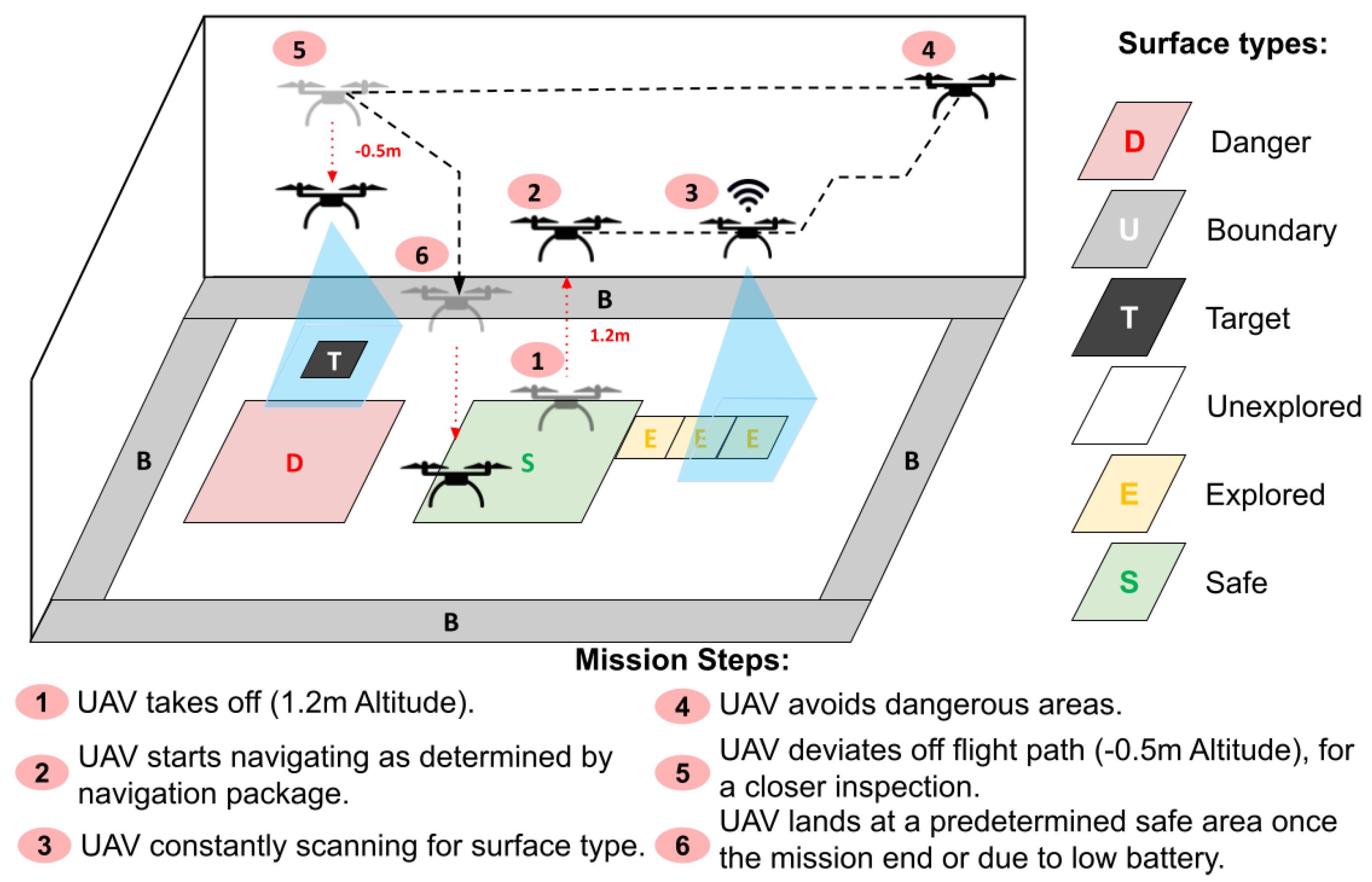
The main observation used for the POMDP formulation is the mission’s current State (St), which is partially observable due to the intrinsic complexity of the tools involved in the navigation and control of the UAV. The uncertainty in the observation was modelled using a sparse categorical probability distribution. The distribution specifies the probabilities of observing a state s t S for a given action a ( t ) A . Table 1 present the probabilities used.

3.1.3. Actions (A)

The proposed actions model the minimum steps required to plan and perform a UAV mission to explore a planetary surface while collecting detailed data on places of interest during the exploration. The finite set of actions a A is defined as follows:
  • Stay  On  the  Ground   ( a = 0 ) : If this action is commanded from a different state to Landed, the navigation module performs a landing action. This action incorporates charging, processing, and idle tasks.
  • Hover ( a = 1 ) : It is a transition action between Take-off, Explore, Inspect and Landing actions. If commanded from the Landed state, a take-off action is attempted; otherwise, this action holds the position of the UAV.
  • Horizontal search or Explore ( a = 2 ) : The Explore action commands the UAV to explore, following which it will change its airborne horizontal position based on the navigation strategy, with a preference for unexplored regions. By performing this action, the UAV aims to explore the map cell by cell.
  • Vertical descend or Inspect ( a = 3 ) : The Inspect action commands the UAV to descend and collect surface data at a higher resolution.
  • Land ( a = 4 ) : This action is the last step to satisfy a successful flight and commands the UAV to navigate to the closest safe landing region and land there.

3.1.4. Transition Function (T)

The transition function generates a future state S t t + 1 probability or belief based on a previous state S t t and an action a t using a sparse categorical probability distribution, explicitly indicating the probability of transition between states after choosing an action (see Figure 6). The transition probabilities are detailed in Table 2.

3.1.5. Reward Function (R)

The reward function is a parameter list that rewards each set (state S t t and action a t ). The reward function uses conditional if statements based on the status of the state S t t to apply the respective rewards, as presented in Algorithm 1. The reward function intends to maximise the time spent inspecting or exploring and addresses the cost of executing a mission, taxing the take-off, hovering, and landing actions. To accomplish that maximisation, positive/big reward values were used for the inspection and explored rewards, while negative/small values were used for other rewards.
Algorithm 1 Reward function R for each state during the UAV mission.
1:
if  S t Landed  then
2:
    if  a StayOnGround  then
3:
        return  r Landed
4:
    else if  a Land  then
5:
        return  r Landing
6:
    end if
7:
else if  s Hovering   then
8:
    return  r Hovering
9:
else if  s Exploring   then
10:
    return  r Exploring
11:
else if  s Inspecting   then
12:
    return  r Inspecting
13:
else if  s Landing   then
14:
    return  r Landing
15:
else
16:
    return  r illegalMovePenalty
17:
end if
 
 
▹ UAV landed reward
 
▹ UAV landing reward
 
 
▹ UAV hovering reward
 
▹ UAV exploring reward
 
▹ UAV inspecting reward


▹ Default reward
 

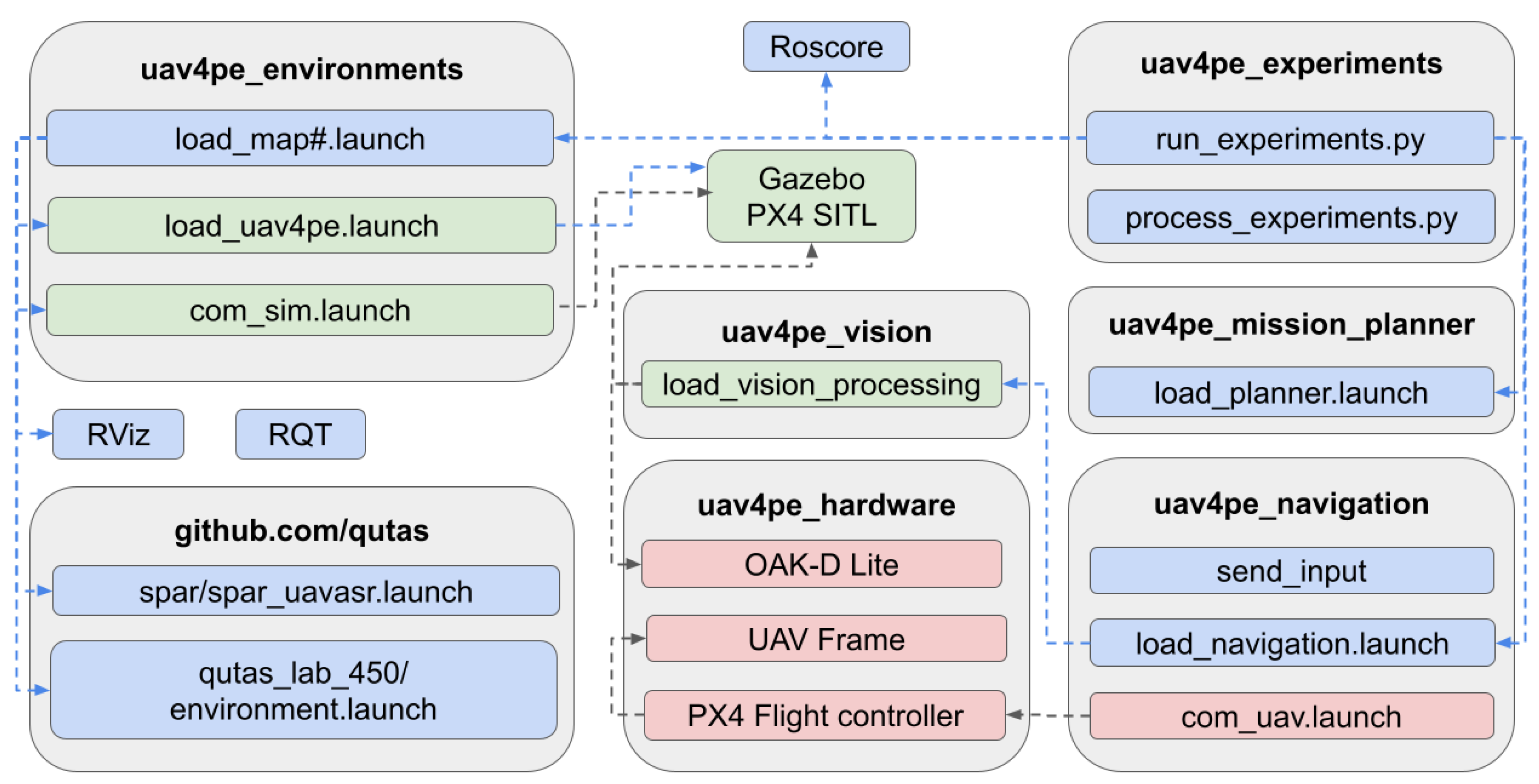
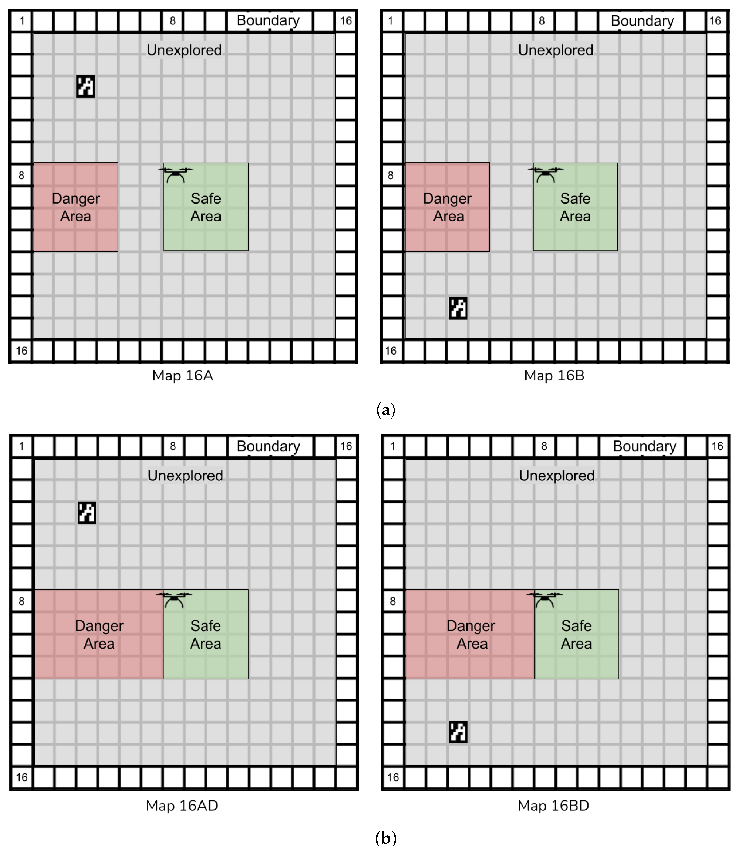
3.2. UAV4PE_Environments

This package contains the 3D models required for the gazebo emulation environment. Furthermore, the UAV4PE_environments package contains launch files to launch the multiple components required in simulation and emulation, as illustrated in Figure 4.

3.3. Github.com/Qutas

Multiple packages from the Queensland University of Technology Aerospace Systems (QUTAS) GitHub were used. The spar_uavasr.launch file from the qutas/spar package was used to run the different nodes required for the simulation environment. The environment.launch file from the qutas/qutas_lab_450 package was used to activate the connection with the motion tracking system in real-world tests and to activate reference frames and safety areas for the UAV motion in simulation, emulation and real-world experiments. Further details can be found in each package repository.

3.4. UAV4PE_Navigation

The UAV4PE_navigation package contains multiple scripts, including a navigation node launched using load_navigation.launch integrated with the POMDP formulation, as discussed in Section 3.1. This navigation node contains a navigation strategy that commands the UAV to the next available and unexplored cell using the following steps: (1) north or up, (2) west or left, (3) south or down, and (4) east or right. If none of the contiguous cells is explorable due to obstacles or already explored cells, the same strategy is applied to n cells: (1) n*cells up, (2) n*cells left, (3) n*cells down, and (4) n*cells right. Additionally, when there are no unexplored cells in the surroundings of the UAV, a navigation action towards the next closest valid cell is taken, moving the UAV towards the next available cell on the map from left to right, and top to bottom. Each test starts with the UAV in the same safe cell [ 8 , 8 ] , in the centre of the map. The navigation strategy node allows for the exploration of adjacent cells while studying the POMDP formulation results, making the navigation steps easily traceable.

3.5. UAV4PE_Vision

This package includes vision-processing scripts based on OpenCV that can be used for emulation and simulation to detect the surface type (red or green) and ArUco markers. During emulation experiments, the images are generated using the Gazebo camera plugging, which creates a camera view attached to the drone. In real-world experiments, an OAK-D lite camera was used.

3.6. UAV4PE_Experiments

This package contains multiple scripts to run experiments and plot the results generated. Simulation and emulation experiments can be run using the script run_experiments.py contained in this package. Each experiment requires a configuration file that stores the minimum details required to replicate the experiments, including POMDP formulation parameters, solver parameters, and maps used. The configuration files are saved using a unique configuration number incremented for each new configuration, e.g., conf1.
The results from each experiment include (1) the navigation logs generated by the UAV4PE_navigation package and (2) the mission planning information in the form of decision trees generated by the UAV4PE_mission_planner package. The results of each experiment are stored using the local machine timestamp, which is stored using the following convention: UAV4PE_experiments/data/configuration/timestamp/map_name. The experimental results in the data folder facilitate the generation of multiple results plots, as presented in the results in Section 6. Experiments using real-world hardware generated data using the same folder conventions as simulation and emulation. However, the execution of the experiments in real hardware required careful execution of the launch scripts presented in Figure 4 to enhance safety.

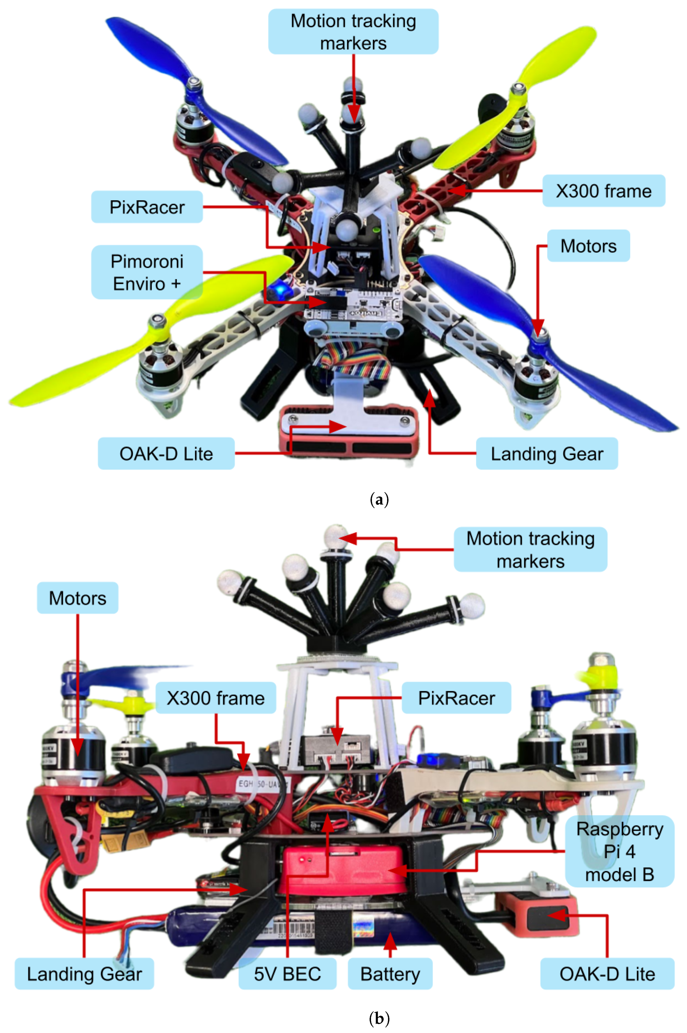
3.7. UAV4PE_Hardware

This package lists and references compatible hardware components that can be used with the framework. The components used in this work are detailed in Section 4.

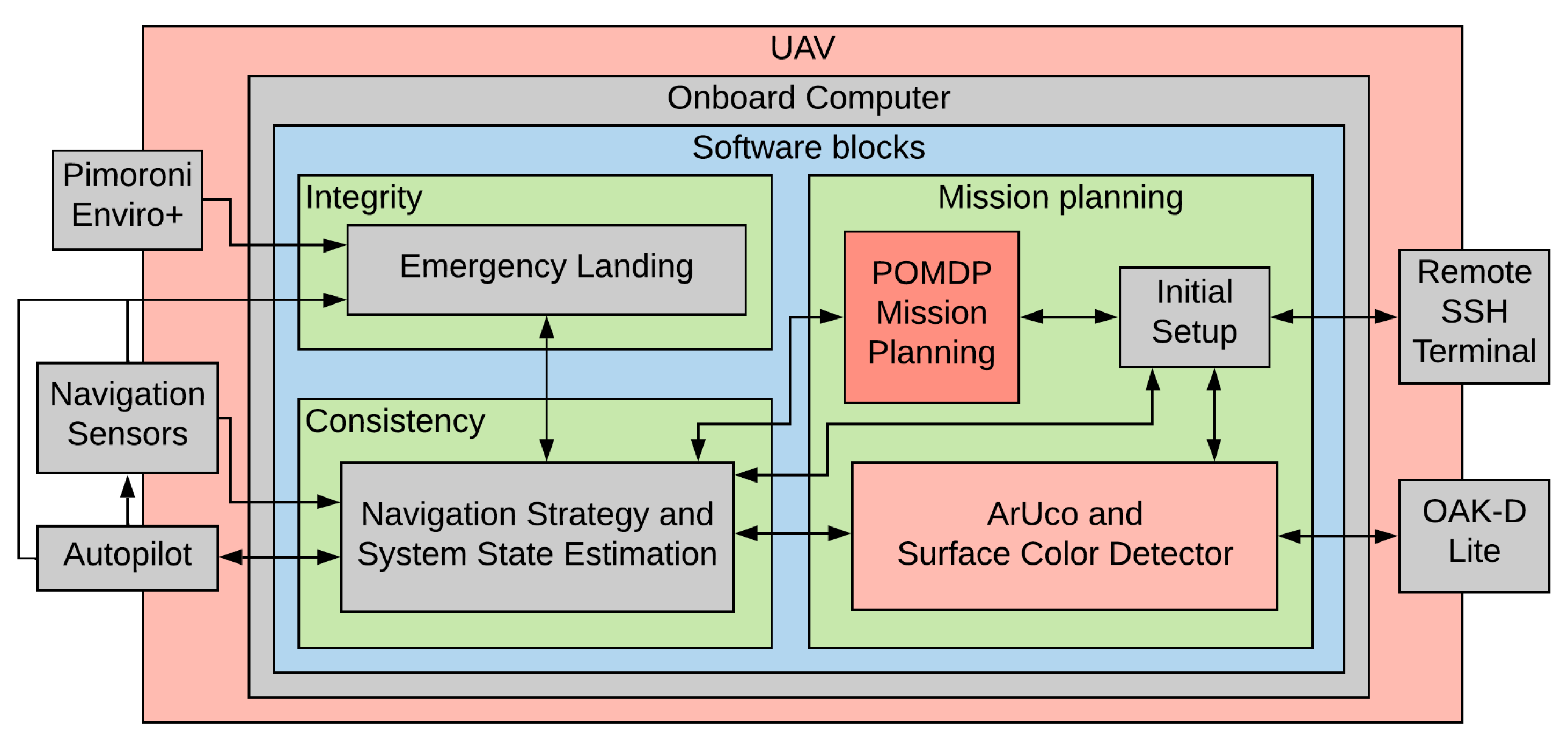
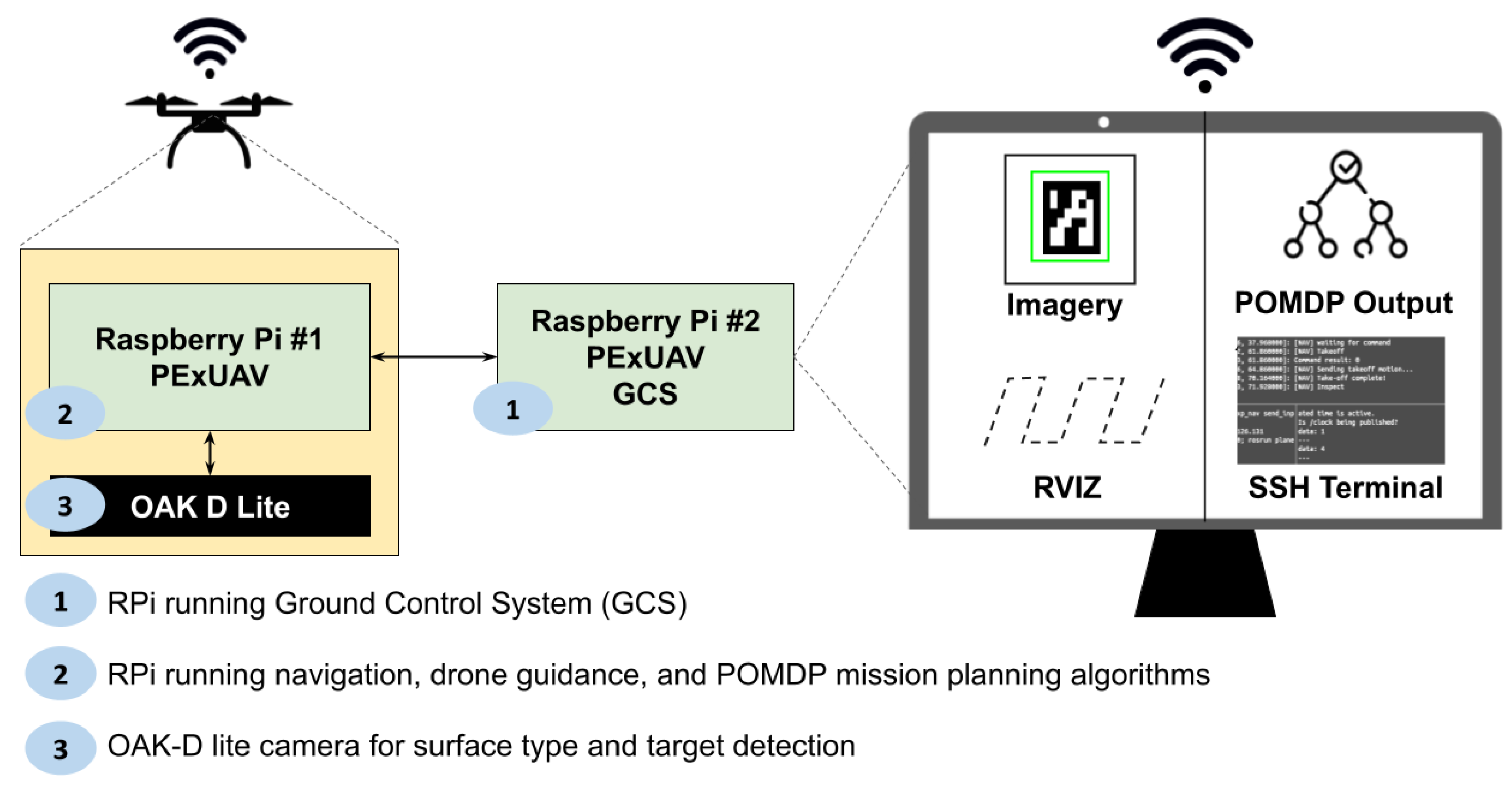
4. System Architecture

The previous literature reviews several design concepts for space exploration using UAVs [7]. However, this work selected a low-cost and commercially off-the-shelf platform as the hardware platform. This facilitates real testing of the framework and UAV platform without requiring sophisticated extraterrestrial testing facilities.
The selected system is a small (under 2 kg) UAV system, composed of an S300 frame, with brushless motors (1400 kv) and 20 Amps Electronic Speed Controllers (ESC), piloted by an mRo PixRacer R15 flight controller, and running PX4 firmware, as described in Figure 7. A Luxonis OAK-D lite fixed-focus camera sensor is used to collect surface images and detect targets and surface types. The fixed focus variation was selected for its performance in high-vibration applications, removing the need for damping systems or gimbals. A Raspberry Pi 4 model B running Ubuntu 20.04 and ROS Noetic is used as the onboard computer. A motion tracking array is placed on top of the UAV to capture the position of the UAV, replacing the GPS system that works outdoors for an indoor UAV local position system. A 3D scanned model of the UAV used in this work is available on Sketfab (https://skfb.ly/oyKuM (accessed on 10 November 2022)).
The system is powered by a 4000 mAh three-cell lithium polymer battery, which provides between 10.5 and 12.6 V in normal operating conditions. The voltage supplied by the battery is regulated to power the flight controller and the onboard computer, which powers other submodules as illustrated in Figure 8 in red. The battery provides up to 10 min of flight endurance while keeping the weight of the UAV under 2 kg. The UAV system uses multiple communication interfaces between the components, including the Universal Asynchronous Receiver-Transmitter serial communication or UART, the Inter-Integrated Circuit synchronous communication or I2C, the Serial Peripheral Interface or SPI, the Pulse Width Modulation or PMW, the Pulse Position Modulation for radio control or PPM, and analog and digital signals, as detailed in Figure 8 in black.
The real UAV system experiments required extra hardware components, including a Ground Control System (GCS), to visualize the results and command the UAV to start the mission. Figure 9 illustrates the connections between the components in the real test case using the Raspberry Pi 4 model B onboard and a Raspberry Pi 4 model B as a GCS.

5. Experiments

A simple experimental scenario was introduced to facilitate testing the framework. The proposed scenario emulates a planetary exploration mission, including some of the main elements that can be expected, such as surface types, targets, and UAV conditions. Four maps were created to test the model under different conditions. The maps include the following six types of surfaces: (1) target, (2) unexplored, (3) safe, (4) explored, (5) boundary and (6) dangerous. The different surfaces introduce risks and potential targets (ArUco marker), which emulate the presence of biosignatures. The map was designed to be easily replicated and implemented virtually and in the real world. The maps implemented are presented in Figure 10. The selected size is 16 × 16 cells, allowing the UAV to execute the exploration mission. Once the UAV moves over a cell, it is marked as explored.

5.1. Experimental Approaches

Three approaches were used to test the framework and scenario proposed in Section 3.1. All the environments use the UAV4PE_mission_planner formulation with the BasicPOMCP solver and the UAV4PE_navigation module, which interfaces with the UAV depending on the scenario being tested, including the following: (1) Simulation using the QUTAS uavasr_emulator that simulates the UAV flight dynamics inside ROS. (2) Emulation using ROS Gazebo simulator and Software In The Loop (SITL) that emulates the UAV flight controller software (PX4). (3) Real-world experiments using the UAV system described in Section 4. The mission concept of operation that applies to the three experimental approaches is presented in Figure 11. The goal is to explore the allocated map in search of a target while avoiding dangerous areas. The target is detected using the ArUco marker OpenCV library in the real test or when the UAV system flies above the ArUco marker location in the simulation. The simulation and emulation experiments were executed using an automated python script within UAV4PE_experiments.

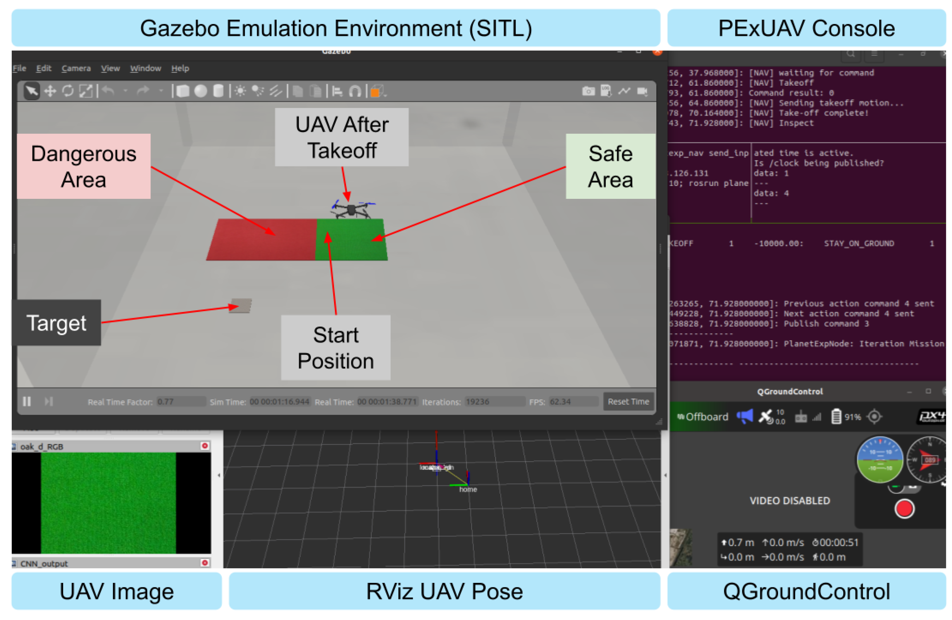
5.1.1. Simulation Environment

The simulation environment facilitates testing of the POMDP formulation presented in Section 3.1 and the basicPOMCP solver parameters. It also provides an ideal testing environment that separates UAV flight controller-related issues, with a clean and simple platform to execute experiments. A screenshot of the simulation environment using RViz is shown in Figure 12.
The simulation includes all the simulation software components presented in Section 3 (ROS, RViz, UAV4PE and QUTAS packages) and the formulation parameters presented in Section 3.1.

5.1.2. Emulated Environment

The mission planner system was tested in an emulation environment using Gazebo (http://gazebosim.org/ (accessed on 10 November 2022)) simulator. The gazebo simulator provides a realistic 3D environment with photo-realistic textures of the real environment. PX4 Software In The Loop (SITL) was used (https://docs.px4.io/master/en/simulation/gazebo.html (accessed on 10 November 2022)), emulating software-level flight controller (autopilot) communication and behaviour. With the flight controller emulation component, this emulation approach drastically reduces the gap between the simulation and the real scenario, granting access to faster system development and debugging. A screenshot of the emulation environment is presented in Figure 13.

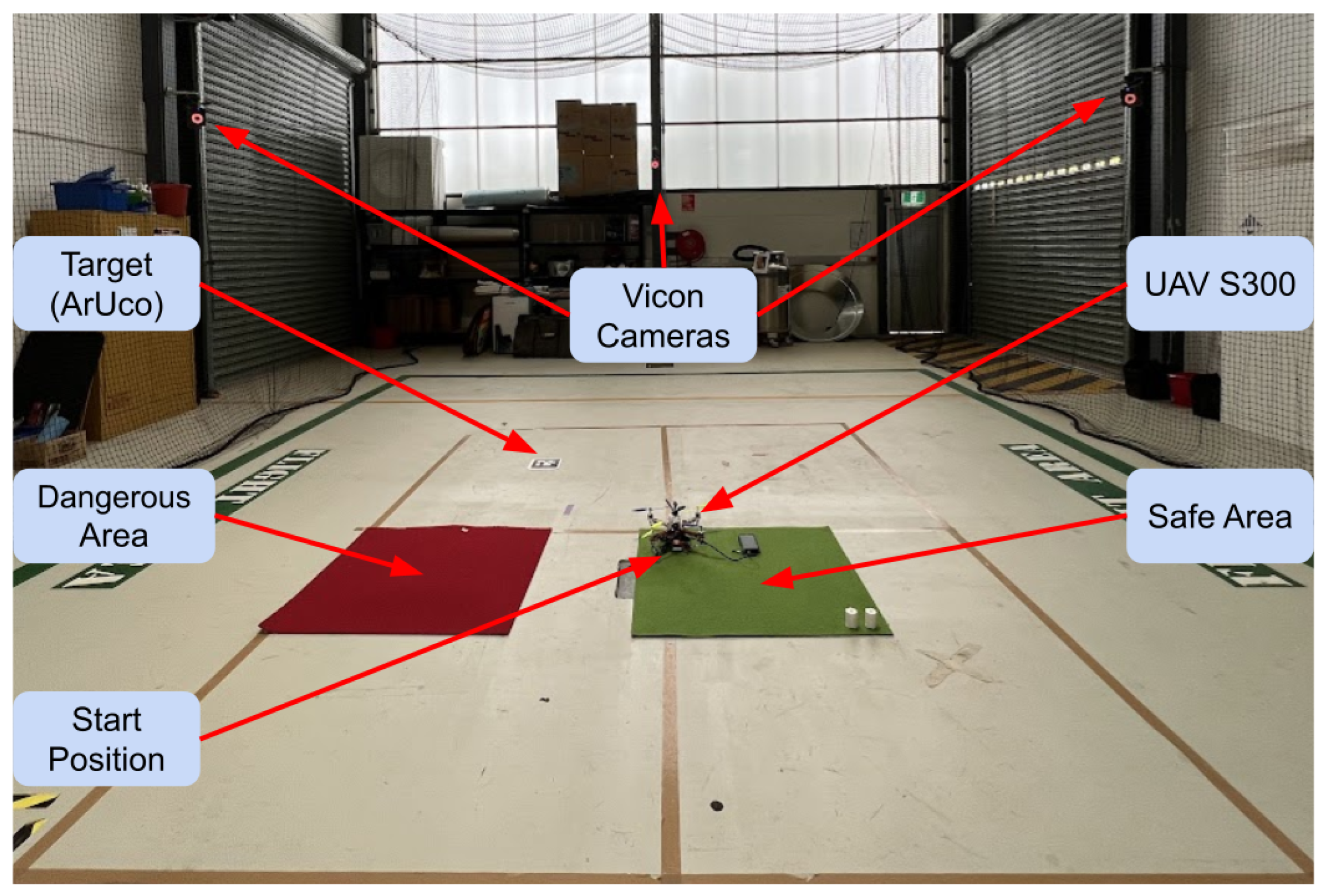
5.1.3. Real Environment

The real test scenario consisted of a 4 m × 4 m flying area with a vision-based position tracking system (Vicon) as the localisation source. The surface retains red and green carpets, following the surface type colour convention for dangerous and safe areas across the testing approaches. A picture of the setup is shown in Figure 14.

5.2. Experiments Setup

Due to the intrinsic probabilistic variations of each experiment, multiple experiments were run for each map and configuration, including twelve experiments for simulation and emulation and four for the real world. Multiple configurations were tested using different parameters for the reward function of the POMDP formulation and the online solver. The reward function presented in Section 3.1.5, Algorithm 1, was configured to reward the exploration and inspection as the mission’s main goals while penalising other states, depending on their impact on battery and mission safety.
The number of configurable parameters in the reward function is six, as defined in Section 3.1. Table A1 and Table A2 summarise the reward (R) values tested in simulation, emulation and real experiments. The number of POMDP solver parameters that can be configured in the basicPOMCP solver is nine. However, this work was limited to a single parameter test for the solver, the discount factor ( γ , see Section 2.3).
Multiple simulation experiments were performed to explore the POMDP solver discount factor ( γ ) parameter influence on the mission planning formulation. This discount factor investigation consists of ten experiments. The experiments used a sub-configuration with identical configuration values and only changed the discount factor. The discount factor was incrementally changed from 0.1 to 0.99, with 0.1 increments.

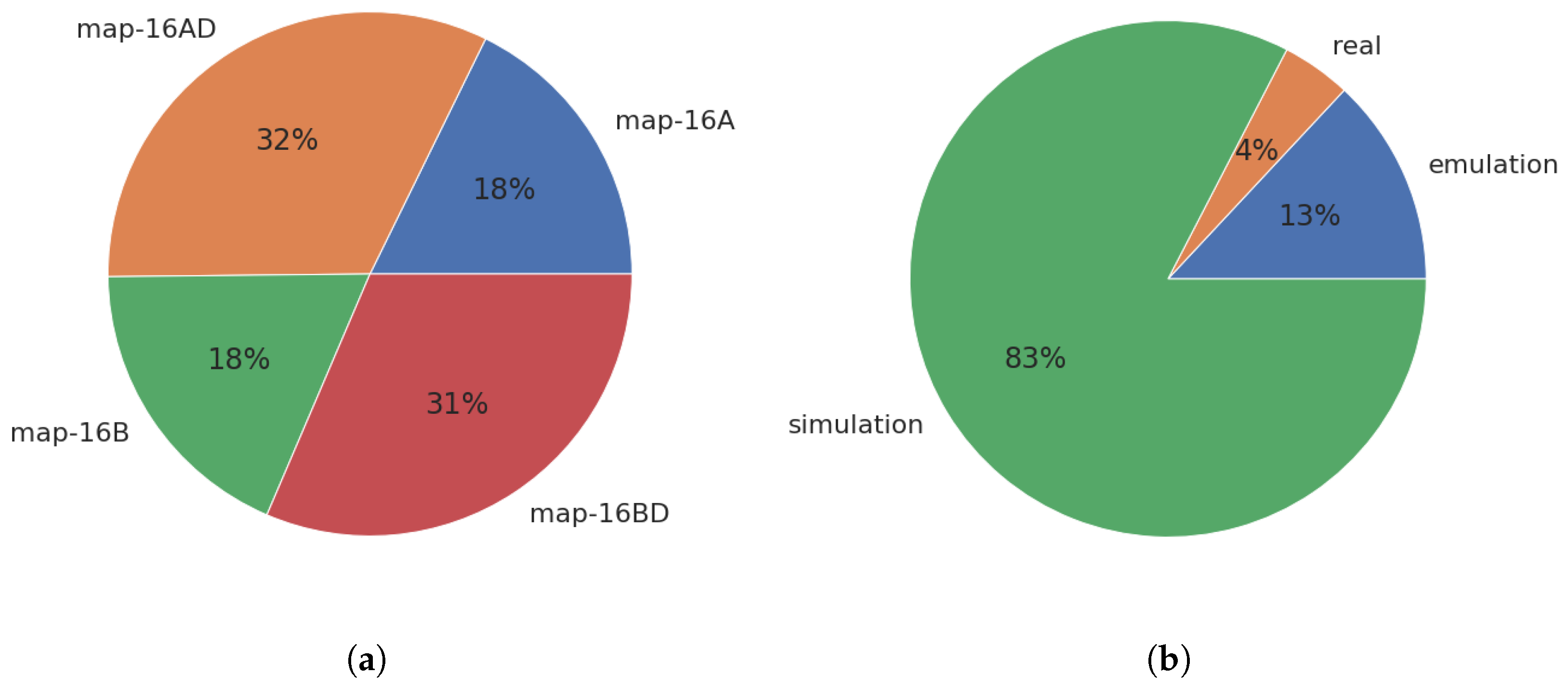
5.3. Data Extraction and Analysis

The data generated during experiments are stored in multiple formats as described in Section 3.6. The data generated from the experiments are processed and stored in a Comma-Separated Value (CSV) file.
The CSV file was loaded into the Jupyter notebook part of the UAV4PE_experiments repository using Google Colab (https://colab.research.google.com/ (accessed on 10 November 2022)). The notebook uses multiple Python data science popular libraries, including Pandas, Matplotlib, seaborn and NumPy. The notebook was used to analyse the results of the experiments, and some of the most relevant analyses are presented in Section 6. However, a wider range of analyses can be found in the original notebook.
The data are stored in a Panda data frame using the structure presented in Table 3. The type column describes the experimental approach of the experiment (simulation, emulation or real). The conf column details the configuration used in the experiment; more details about tested configurations can be found in Table A1 and Table A2. The expFolder column retains information about the experimental execution date and the folder name where the raw data were stored. The map describes the map used in the experiments; the map options were described in Section 5. The expNumber describes the experiment identification number using a counter that starts from zero for each new experiment configuration.
Finally, a new metric is introduced to identify the parameter configuration that maximises the exploration performance in terms of the total area explored, the number of actions performed and if the target is found. The metric was called exploredRatio, and Equation (2) presents how it was computed for each experiment using the variable names introduced in Table 3.
e x p l o r e d R a t i o = t a r g e t F o u n d ( e x p l o r e d A r e a / a c t i o n s T o t a l )

Data Filtering

Multiple filters were applied to the data to filter nullified experiments (due to tool issues) and to extract the data from different perspectives. One of the first filters removed the experiments where the area explored was equal to zero. Eleven experiments were found in emulation with a zero area explored. This was attributed to communication issues with the emulated UAV in Gazebo (UAV arming command rejected, avoiding UAV to take-off).
The experiments that successfully managed to explore 100% of the maps were also extracted. This extracted data were used to compare the configurations that successfully completed the mission and yielded the best performance (fewer action counts).
The data were also filtered to extract configurations tested in all three experimental approaches, including simulation, emulation and real-world experiments, showing the UAV4PE framework behaviour differences and similarities in those approaches.

6. Results

A total of 2112 experiments were used for analysis, distributed into 1659 experiments in simulation, 409 experiments in emulation and 44 real flights. Of all the experiments for the configurations tested, just 395 (18.7%) successfully completed the mission, exploring 100% of the map. Table 4 summarises the experiments, providing details about minimum and maximum values, standard deviation (std), the mean and percentiles.
The overall results mean values grouped by map and configuration type are presented in Table 5. The Experiment Number column shows an experimental number that reflects the predominance of simulation and emulation experiments compared to the number of real experiments. The Target Found column indicates that experiments using maps 16A and 16AD found the target more often than experiments using 16B and 16BD. This is attributed to the navigation strategy that prioritizes exploring the top left side of the maps where the target is located in 16A and 16AD. The Area Explored column indicates that more area was explored in real experiments, followed by emulation experiments and simulation. The main reason for this explored area difference is the limited configurations used in real experiments (best configurations) compared to those tested on emulation and simulation. The Takeoffs Count column shows that the experiments on emulation performed fewer takeoffs. Finally, the Actions Count column indicates that simulation experiments executed more actions than emulation and real experiments. This difference is attributed to the relatively higher number of experiments and configurations tested on simulation. The overall results from Table 5 show the mean dataset distribution and wide information about the differences between the maps and experimental-type approaches. However, it provides a narrow understanding of the POMDP formulation behaviour due to the broader set of configurations presented. A further analysis in Section 6.1 provides detailed information about the POMDP formulation behaviour and the configurations that yield the most promising results.

6.1. Successful Missions Analysis

A successful mission was defined as a mission where the map explorable area is fully explored, and the target is found. A partially successful mission was defined as a mission where the target is found, but the map’s explorable area was not fully explored. Following these definitions, 299 experiments were successful with 100% of the explorable area explored, while the target was found in 946 experiments. Experiments with configuration conf0 were excluded from this analysis as they were generated as a baseline metric and are successful by definition. Figure 15 shows the average success distribution for all the successful configurations tested grouped by the maps (see Figure 15a) and by experiment type (see Figure 15b), indicating a higher percentage of successful missions for the maps with increased dangerous area 16AD and 16BD compared to maps 16A and 16B. This indicates that successful missions are more likely to occur on maps with fewer explorable cells. Additionally, Figure 15b highlights the predominance of simulation and emulation results within the experiments.
Partially successful mission results indicate the target was found in higher ratios in the maps 16A and m16AD, as presented in Figure 16a. This difference is attributed to the navigation strategy prioritising the exploration of the top-left area of the maps, where the target in 16A and 16AD is placed. This highlights the direct influence of navigation strategy and mission planning. Additionally, keeping the navigation module simple during the initial tuning and development of the mission planning formulation is important so the results can be analysed.
The configurations that yielded successful missions are presented in Figure 17, where the total number of actions to achieve the success is also illustrated. The configurations with the smaller number of actions are more efficient, meaning they require fewer actions to complete the mission.
The configurations conf1, conf2, conf7.1 and conf8, showed more efficient behaviours. However, the number of experiments for each configuration presented in Table A3 indicates that configurations conf1 and conf2 yield few successful missions, which, based on the twelve experiments per map experimental setup, can be attributed to glitches in the emulation approach. The next configuration with enough successful mission experiments is conf7.1, which presents eleven successful cases in real experiments, 32 in emulation and 20 in simulation (see Table A3). Thus, configuration conf7.1 consistently yielded the most successful mission experiments across experimental types.
The exploredRatio metric introduced in Section 5.2 was used to visualise and compare the configurations responsible for successful missions. Figure 18 presents the exploredRatio metric for each configuration and map. The higher the exploredRatio metric, the more efficient the configuration. Baseline configuration conf0 shows the theoretical maximum exploration ratio value, followed by configuration conf7.1. This metric provides a direct way to measure and compare the UAV-based POMDP mission planning configuration performance.
Two configurations (conf 7.1 and conf8) were tested on all the experimental type approaches, including simulation, emulation and real-world. Figure 19 presents comparative results showing that results for all maps and configurations in the real-world experiments used fewer actions to complete the mission successfully. This is attributed to differences in the maximum speed of the real UAV and the UAV model dynamics used in simulation and emulation. The figure also shows that 16AD and 16DB were completed with the fewest actions on average in the simulation and emulation experiments. In real experiments, maps 16AD and 16DB showed larger standard deviations than maps 16A and 16D due to the higher number of successful experiments for maps 16AD and 16DB.

7. Conclusions and Future Work

The results presented here show an approach to modelling UAV mission planning for planetary exploration using POMDP. The proposed POMDP formulation successfully planned and commanded a UAV in simulation, emulation and real-world experiments, exploring multiple maps and finding a target in different unknown locations. The low percentage of successful experiments, of around 18.7% over the total configuration tests, indicates that optimal configurations are not trivial. However, successful configurations, such as conf7.1, show that POMDP formulations can successfully plan UAV missions for planetary exploration. The results in this work condense the analysis provided in the UAV4PE_experiments notebook, which can be further explored to find detailed relations between configurations.
This work also introduces the main aspects of the UAV4PE framework, for which source code can be accessed to be reused and extended, providing extra tools to develop more autonomous and more robust mission planning strategies transferable to real-world applications. The result presented in this work can be used as a benchmark and baseline for further UAV autonomous mission planning studies. The data analysis notebook provides a powerful tool for using data science libraries to extract informative knowledge from the UAV4PE framework experiments. Furthermore, the new metric introduced in Section 5.2 can be used as a configuration fitness metric, facilitating further studies, for example, using genetic algorithms to search for optimal parameter configurations for the POMDP formulation and solver.
Future work focusing on UAV platforms that resemble UAV concepts for space exploration is encouraged. The development of systems for self-rescue in case of malfunctions is recommended. For this work, the scope was limited to a compact setup that can be replicated affordably, given the challenges related to testing UAV concepts in extraterrestrial environments. Nevertheless, the simulation and emulation environment can be modified to replicate extraterrestrial conditions using the Gazebo physics engine and the simulator UAV motion equations. Safety guidelines for UAV operation must be followed for real-world experiments. Moreover, additional safety features, such as netted flying area facilities, propeller guards, and UAV motor arming safe checks, are recommended. The experiments presented in this work can be extended in future work by adding, for example, experiments with terrain variations and momentary environmental changes such as wind gusts. Future work could focus on the inclusion of more realistic planetary exploration environments such as Mars landscapes and 3D terrain models provided by NASA (https://github.com/nasa/NASA-3D-Resources (accessed on 10 November 2022)). Additionally, natural 3D surfaces digitised via photogrametry with realistic targets can be added using Digital Elevation Models (DEM) or Meshes.
Further improvements can be achieved in the mission planning formulation. The framework modularity allows for adding more detailed and precise models to describe additional system observations and actions. Environment-aware observations such as the sun and wind effects can be introduced. Mission planning formulations can benefit from the inclusion of energy storage dynamics, power management and harvesting, supplementary surface types, and uncertainty in emulating a GPS-denied environment such as Mars. A UAV endurance analysis can also be performed in future work to identify its impact on mission planning in different environments such as Mars or Antarctica. We used an ArUco marker detector as the biosignature detector module; however, we also developed a biosignature detection system separately [12].
Ongoing work aims to enhance the model definition and formulation, improve the framework’s documentation, and explore the influence of broader solver configurations. Future work also will involve migrating the packages in the framework to ROS2.

Author Contributions

Conceptualization, J.G.-S., F.V., D.F. and F.G.; methodology, J.G.-S., F.V. and F.G.; software, J.G.-S., S.B. and J.S.; validation, J.G.-S.; formal analysis, J.G.-S.; investigation, J.G.-S.; resources, F.G.; data curation, J.G.-S.; writing—original draft preparation, J.G.-S.; writing—review and editing, S.B., F.V., J.S., D.F. and F.G.; visualization, J.G.-S.; supervision, F.V., D.F. and F.G.; project administration, F.G.; funding acquisition, F.G. All authors have read and agreed to the published version of the manuscript.

Funding

The 3rd author would like to acknowledge The Australian Research Council (ARC) through the ARC Discovery Project 2020, “When every second counts: Multi-drone navigation in GPS-denied environments” (grant number ARC DP200101640).

Data Availability Statement

The collected data supporting this article’s research findings are available in UAV4PE_experiments/data.

Acknowledgments

The authors acknowledge the continued support from the Queensland University of Technology (QUT) through the QUT Centre for Robotics (QCR) and Engineering Faculty for allowing access and flight test at QUT’s Davinci Precinct. We also acknowledge the QUT Research Engineering Facility (REF), Kye Morton from the QUTAS flight Stack, and Zachary Sunberg from the Julia POMDP library.

Conflicts of Interest

The authors declare no conflict of interest. The funders had no role in the design of the study; in the collection, analyses, or interpretation of data; in the writing of the manuscript, or in the decision to publish the results.

Abbreviations

The following abbreviations are used in this manuscript:
UAVUnmanned Aerial Vehicle
POMDPPartially Observable Markov Decision Process
ArUcoAugmented Reality University of Cordoba
ROSRobot Operating System
GPSGlobal Positioning System
NASANational Aeronautics and Space Administration
I2CInter-Integrated Circuit
UARTUniversal Asynchronous Receiver-Transmitter serial communication
SPISerial Peripheral Interface
PMWPulse Width Modulation
PPMPulse Position Modulation for radio control
MSOMars Science Orbiter
GCSGround Control System
SITLSoftware In The Loop
CSVComma Separated Values
CPUCentral Processing Unit
DEMDigital Elevation Model

Appendix A. Additonal Experiments

Table A1. Configurations 0 to 7.1 tested. S for simulation, E for emulation and R for the real world.
ParametersConfiguration Number (Conf_#)
Configuration Number012345677.1
Configuration used in:SS,ES,ESSSSSS,E,R
maxRunTime (secs)720360360360360360360360,600,720360,600,720
discountFactor-0.90.990.90.990.90.990.990.9
nSteps-100100100100100100100100
maxDepthTree-2020202020202020
inspectingReward-202011222020
exploringReward-505055555050
landedReward-1100−2−2−10−10
landingReward-−15−15−2−2−2−2−15−15
hoveringReward-−10−10−2−2−2−2−10−10
illegalMovePenalty-−2−2−2−2−2−2−2−2
Table A2. Configurations 7.2 to 12 tested. S for simulation, E for emulation and R for the real world.
ParametersConfiguration Number (Conf_#)
Configuration Number7.2–7.988.19101112
Configuration used in:SS,E,RRSSSS
maxRunTime (secs)720360,600600600600600600
discountFactor(0.8–0.1)0.990.90.990.990.990.99
nSteps100100100100100100100
maxDepthTree20202020202020
inspectingReward2020200222
exploringReward5050505555
landedReward−10−10−100111
landingReward−15−10−10000−1
hoveringReward−10−10−10000−1
illegalMovePenalty−2−2−2−100−10−50−50
Table A3. Total number of actions analysis of the configurations that yielded successful mission.
CountMeanStdMin25%50%75%Max
ConfType
conf1emulation4.033.0000000.81649732.032.7533.033.2534.0
conf8emulation2.035.0000002.82842733.034.0035.036.0037.0
conf7.1real11.035.1818186.53939125.031.5035.038.5046.0
conf2emulation1.036.000000NaN36.036.0036.036.0036.0
conf8real2.042.0000009.89949535.038.5042.045.5049.0
conf7.1emulation32.048.5000009.70533629.040.7550.555.0067.0
conf8simulation10.055.4000002.01108051.054.2556.056.7558.0
conf7.3simulation41.060.5609767.25275441.056.0063.066.0069.0
conf7.6simulation28.060.5714295.82096242.057.7561.064.2569.0
conf7.2simulation32.060.8125006.98125446.056.0062.067.0070.0
conf7.5simulation37.061.0810815.80411052.055.0062.066.0071.0
conf7.4simulation37.061.7297304.79379649.058.0062.066.0069.0
conf7.1simulation20.062.9000006.74263747.057.5065.567.5071.0
conf7.7simulation22.063.0000004.85013554.060.2564.066.7570.0
conf7simulation2.064.5000007.77817559.061.7564.567.2570.0
conf7.8simulation15.064.5333335.61715149.063.0065.068.5070.0
conf7.9simulation3.067.6666671.52752566.067.0068.068.5069.0

References

  1. Toro, F.G.; Tsourdos, A. UAV Sensors for Environmental Monitoring; MDPI: Basel, Switzerland, 2018. [Google Scholar]
  2. Rojas, A.J.; Gonzalez, L.F.; Motta, N.; Villa, T.F. Design and flight testing of an integrated solar powered UAV and WSN for remote gas sensing. In Proceedings of the 2015 IEEE Aerospace Conference, Big Sky, MT, USA, 7–14 March 2015; Mattingly, R., Ed.; IEEE: Piscataway, NJ, USA, 2015; Volume 2015, pp. 1–10. [Google Scholar]
  3. Al-Sabban, W.H.; Gonzalez, L.F.; Smith, R.N. Wind-energy based path planning for Unmanned Aerial Vehicles using Markov Decision Processes. In Proceedings of the 2013 IEEE International Conference on Robotics and Automation, Karlsruhe, Germany, 6–10 May 2013; Vincze, M., Ed.; IEEE: Piscataway, NJ, USA, 2013; pp. 784–789. [Google Scholar]
  4. Saffre, F.; Hildmann, H.; Karvonen, H.; Lind, T. Monitoring and Cordoning Wildfires with an Autonomous Swarm of Unmanned Aerial Vehicles. Drones 2022, 6, 301. [Google Scholar] [CrossRef]
  5. Serna, J.G.; Vanegas, F.; Gonzalez, F.; Flannery, D. A Review of Current Approaches for UAV Autonomous Mission Planning for Mars Biosignatures Detection. In Proceedings of the 2020 IEEE Aerospace Conference, Big Sky, MT, USA, 7–14 March 2020; Institute of Electrical and Electronics Engineers Inc.: Piscataway, NJ, USA, 2020. IEEE Aerospace Conference Proceedings. pp. 1–15. [Google Scholar]
  6. Ingenuity. Available online: https://www.jpl.nasa.gov/missions/ingenuity (accessed on 22 August 2022).
  7. Hassanalian, M.; Rice, D.; Abdelkefi, A. Evolution of space drones for planetary exploration: A review. Prog. Aerosp. Sci. 2018, 97, 61–105. [Google Scholar] [CrossRef]
  8. Balaram, B.; Canham, T.; Duncan, C.; Grip, H.F.; Johnson, W.; Maki, J.; Quon, A.; Stern, R.; Zhu, D. Mars helicopter technology demonstrator. In Proceedings of the 2018 AIAA Atmospheric Flight Mechanics Conference, Atlanta, Georgia, 25–29 June 2018; American Institute of Aeronautics and Astronautics: Reston, VA, USA, 2018; pp. 1–18. [Google Scholar]
  9. Lorenz, R.D.; Turtle, E.P.; Barnes, J.W.; Trainer, M.G.; Adams, D.; Hibbard, K.E.; Sheldon, C.Z.; Zacny, K.; Peplowski, P.N.; Lawrence, D.J.; et al. Dragonfly: A rotorcraft lander concept for scientific exploration at Titan. Johns Hopkins APL Tech. Dig. 2018, 34, 374–387. [Google Scholar]
  10. Pipenberg, B.T.; Langberg, S.A.; Tyler, J.D.; Keennon, M.T. Conceptual Design of a Mars Rotorcraft for Future Sample Fetch Missions. In Proceedings of the 2022 IEEE Aerospace Conference (AERO), Big Sky, MT, USA, 5–12 March 2022; pp. 1–14. [Google Scholar]
  11. Westall, F.; Cavalazzi, B. Biosignatures in Rocks. In Encyclopedia of Geobiology; Reitner, J., Thiel, V., Eds.; Springer: Dordrecht, The Netherlands, 2011; pp. 189–201. [Google Scholar]
  12. Galvez-Serna, J.; Mandel, N.; Sandino, J.; Vanegas, F.; Ly, N.; Flannery, D.T.; Gonzalez, F. Real-time Segmentation of Desiccation Cracks onboard UAVs for Planetary Exploration. In Proceedings of the 2022 IEEE Aerospace Conference (AERO), Big Sky, MT, USA, 5–12 March 2022; pp. 1–12. [Google Scholar]
  13. Johnson, A.; Fox, K. NASA’s Ingenuity Mars Helicopter to Begin New Demonstration Phase; NASA: Washington, DC, USA, 2021. [Google Scholar]
  14. Johnson, A.; Fox, K. My Favorite Martian Image: Helicopter Sees Potential Rover Road Ahead–NASA’s Mars Exploration Program; NASA: Washington, DC, USA, 2021. [Google Scholar]
  15. Tzanetos, T.; Aung, M.; Balaram, J.; Grip, H.F.; Karras, J.T.; Canham, T.K.; Kubiak, G.; Anderson, J.; Merewether, G.; Starch, M.; et al. Ingenuity Mars Helicopter: From Technology Demonstration to Extraterrestrial Scout. In Proceedings of the 2022 IEEE Aerospace Conference (AERO), Big Sky, MT, USA, 5–12 March 2022; pp. 01–19. [Google Scholar]
  16. Sasaki, T.; Otsu, K.; Thakker, R.; Haesaert, S.; Agha-mohammadi, A.A. Where to Map? Iterative Rover-Copter Path Planning for Mars Exploration. IEEE Robot. Autom. Lett. 2020, 5, 2123–2130. [Google Scholar] [CrossRef]
  17. Atyabi, A.; MahmoudZadeh, S.; Nefti-Meziani, S. Current advancements on autonomous mission planning and management systems: An AUV and UAV perspective. Annu. Rev. Control 2018, 46, 196–215. [Google Scholar] [CrossRef]
  18. Zermani, S.; Dezan, C.; Euler, R. Embedded decision making for UAV missions. In Proceedings of the 2017 6th Mediterranean Conference on Embedded Computing, MECO 2017–Including ECYPS 2017, Bar, MT, USA, 11–15 June 2017; Institute of Electrical and Electronics Engineers Inc.: Piscataway, NJ, USA, 2017. [Google Scholar]
  19. Campo, L.V.; Ledezma, A.; Corrales, J.C. MCO Plan: Efficient Coverage Mission for Multiple Micro Aerial Vehicles Modeled as Agents. Drones 2022, 6, 181. [Google Scholar] [CrossRef]
  20. Vanegas, F.; Gaston, K.J.; Roberts, J.; Gonzalez, F. A Framework for UAV Navigation and Exploration in GPS-Denied Environments. In Proceedings of the IEEE Aerospace Conference Proceedings. IEEE Computer Society, Big Sky, MT, USA, 2–9 March 2019; Volume 2019. [Google Scholar]
  21. Allak, E.; Brommer, C.; Dallenbach, D.; Weiss, S. AMADEE-18: Vision-Based Unmanned Aerial Vehicle Navigation for Analog Mars Mission (AVI-NAV). Astrobiology 2020, 20, 1321–1337. [Google Scholar] [CrossRef] [PubMed]
  22. Sandino, J.; Vanegas, F.; Gonzalez, F.; Maire, F. Autonomous UAV Navigation for Active Perception of Targets in Uncertain and Cluttered Environments. In Proceedings of the 2020 IEEE Aerospace Conference, Big Sky, MT, USA, 7–14 March 2020; pp. 1–12. [Google Scholar]
  23. Sandino, J.; Vanegas, F.; Maire, F.; Caccetta, P.; Sanderson, C.; Gonzalez, F. UAV framework for autonomous onboard navigation and people/object detection in cluttered indoor environments. Remote Sens. 2020, 12, 3386. [Google Scholar] [CrossRef]
  24. Galvez-Serna, J.; Vanegas, F.; Gonzalez, F.; Flannery, D. Towards a Probabilistic Based Autonomous UAV Mission Planning for Planetary Exploration. In Proceedings of the 2021 IEEE Aerospace Conference (50100), IEEE Computer Society, Big Sky, MT, USA, 6–13 March 2021; Volume 2021, pp. 1–8. [Google Scholar]
  25. Kim, S.K.; Salzman, O.; Likhachev, M. POMHDP: Search-Based Belief Space Planning Using Multiple Heuristics. ICAPS 2019, 29, 734–744. [Google Scholar] [CrossRef]
  26. Hireche, C.; Dezan, C.; Diguet, J.P.; Mejias, L. BFM: A Scalable and Resource-Aware Method for Adaptive Mission Planning of UAVs. In Proceedings of the 2018 IEEE International Conference on Robotics and Automation (ICRA), Brisbane, Australia, 21–25 May 2018; Institute of Electrical and Electronics Engineers Inc.: New Jersey, USA, 2018; pp. 6702–6707. [Google Scholar]
  27. Kaelbling, L.P.; Littman, M.L.; Cassandra, A.R. Planning and acting in partially observable stochastic domains. Artif. Intell. 1998, 101, 99–134. [Google Scholar] [CrossRef] [Green Version]
  28. Vanegas, F.; Gonzalez, F. Enabling UAV Navigation with Sensor and Environmental Uncertainty in Cluttered and GPS-Denied Environments. Sensors 2016, 16, 666. [Google Scholar] [CrossRef] [PubMed]
  29. Hireche, C.; Dezan, C.; Mocanu, S.; Heller, D.; Diguet, J.P. Context/Resource-Aware Mission Planning Based on BNs and Concurrent MDPs for Autonomous UAVs. Sensors 2018, 18, 4266. [Google Scholar] [CrossRef] [PubMed] [Green Version]
  30. Silver, D.; Veness, J. Monte-Carlo Planning in Large POMDPs. In Advances in Neural Information Processing Systems; Lafferty, J., Williams, C., Shawe-Taylor, J., Zemel, R., Culotta, A., Eds.; Curran Associates, Inc.: Red Hook, NY, USA, 2010; Volume 23. [Google Scholar]
  31. Serna, J.G.; Gonzalez, F.; Alvarez, F.V.; Flannery, D. A Probabilistic based UAV Mission Planning and Navigation for Planetary Exploration. In Proceedings of the 2020 International Conference on Unmanned Aircraft Systems: ICUAS’20, Athens, Greece, 1–4 September 2020; pp. 594–599. [Google Scholar]
  32. Walker, O.; Vanegas, F.; Gonzalez, F. A Framework for Multi-Agent UAV Exploration and Target-Finding in GPS-Denied and Partially Observable Environments. Sensors 2020, 20, 4739. [Google Scholar] [CrossRef] [PubMed]
  33. Canham, T. The Mars Ingenuity Helicopter—A Victory for Open-Source Software. In Proceedings of the 2022 IEEE Aerospace Conference (AERO), Big Sky, MT, USA, 5–12 March 2022; pp. 1–11. [Google Scholar]
  34. Egorov, M.; Sunberg, Z.N.; Balaban, E.; Wheeler, T.A.; Gupta, J.K.; Kochenderfer, M.J. POMDPs.jl: A Framework for Sequential Decision Making under Uncertainty. J. Mach. Learn. Res. 2017, 18, 1–5. [Google Scholar]
  35. Klimenko, D.; Song, J.; Kurniawati, H. TAPIR: A software Toolkit for approximating and adapting POMDP solutions online. In Proceedings of the Australasian Conference on Robotics and Automation, Melbourne, Australia, 2–4 December 2014; Volume 24. [Google Scholar]
  36. Thrun, S.; Burgard, W.; Fox, D. Probabilistic Robotics; The MIT Press: Cambridge, UK, 2005; Volume 45, p. 668. [Google Scholar]
Figure 1. Ingenuity helicopter on Mars during sol 46. Credits: NASA/JPL.
Drones 06 00391 g001
Figure 2. Future UAVs for planetary exploration. (a) Dragonfly, a UAV for Titan. Credits: NASA/APL. (b) Mars Science Helicopter (MSH) concept. Credits: NASA/JPL-Caltech. (c) Mars sample return helicopter proposal. Credits: NASA/JPL-Caltech.
Drones 06 00391 g002
Figure 3. UAV4PE framework architecture, where the Consistency, Integrity, and Mission Planner block were simplified.
Drones 06 00391 g003
Figure 4. ROS architecture implemented. Simulation components are in blue, emulation components are in green, and hardware components are in red. Some components from the simulation can be used in emulation and when real-world hardware tests are conducted. The black arrows indicate connection dependency, while the blue arrow indicates that the pointed component is executed when the source component is executed. Please check the GitHub repository (qutas/UAV4PE) for future updates in this diagram.
Drones 06 00391 g004
Figure 5. UAV in a planetary exploration mission. The formulated system States are (1) Landed; (2) Hovering; (3) Horizontal exploration; (4) Vertical inspection, and (5) Landing. The arrows indicate the action with the highest probability of moving the UAV to that state. Green areas are safe for landing, while red areas are dangerous to land over.
Drones 06 00391 g005
Figure 6. Transition function representation. The circles represent the modelled states, and the arrows indicate actions. The actions connect the initial and potential subsequent states.
Drones 06 00391 g006
Figure 7. UAV S300 system hosting the OAK-D lite camera and Pimoroni Enviro+ sensor as payload, a Raspberry Pi 4 model B as an onboard computer, and a Pixracer R15 autopilot. (a) Frontal view of the hardware system, showing main components. (b) Lateral view of the hardware system, showing main components.
Drones 06 00391 g007
Figure 8. UAV System architecture detailing power distribution from the battery to main components and peripherals using red arrows. The signals are also illustrated with black arrows detailing signal types between components. The components partially outside the X500 Frame box in grey represent physical interaction with the environment.
Drones 06 00391 g008
Figure 9. System main components and remote data visualisation interfaces.
Drones 06 00391 g009
Figure 10. Maps proposed to compare the POMDP mission planning. ArUco markers represent biosignatures, red areas are dangerous places to fly over, and green areas are safe places to land. The UAV starts over the green area in the centre of the map. (a) Maps with different target locations. (b) Maps with a slightly larger danger zone.
Drones 06 00391 g010
Figure 11. Mission concept of operation, illustrating the test scenario, the expected mission steps, and surface types.
Drones 06 00391 g011
Figure 12. Rviz simulation environment screenshot after exploring map 16. The exploration path follows the navigation strategy presented and explained in Section 3.4. The traversed path is plotted with orientation and position over time. Some traces of the mission phases are pointed out, including the start position, the exploration path and the return to the home path.
Drones 06 00391 g012
Figure 13. Gazebo simulation of proposed environment running Software In The Loop (SITL). QgroundControl was used to visualize the UAV attitude, flight mode and battery percentage. The UAV4PE console is a Tmux session where the UAV4PE launch files for simulation and emulation run.
Drones 06 00391 g013
Figure 14. Indoor real-world environment using Vicon motion tracking system.
Drones 06 00391 g014
Figure 15. Plots (a,b) show the average results for all the experiments that successfully completed the mission, defined as exploring 100% of the total area explorable in the selected map. (a) Success missions distribution grouped by map. (b) Success missions distribution grouped by experimental type.
Drones 06 00391 g015
Figure 16. Plots (a,b) show the average results for all the experiments that partially complete the mission, where the target is found without exploring 100% of the total area explorable in the selected map. (a) Mission where the target was found grouped by map. (b) Mission where the target was found grouped by experimental type.
Drones 06 00391 g016
Figure 17. Total number of actions needed to complete the mission for all the configurations that yielded successful missions.
Drones 06 00391 g017
Figure 18. ExploredRatio metric for all the configurations that yield successful missions.
Drones 06 00391 g018
Figure 19. Total number of actions required to complete the mission successfully for the configurations conf7.1 and conf8 tested on all experimental types and grouped by map.
Drones 06 00391 g019
Table 1. Observation probabilities values for all the possible states S t t + 1 after selecting an action a t .
Observation Probability for State St t + 1
Action ( a ( t ) A ) LandedHoveringExploringInspectingLanding
Stay on ground0.90.030.010.010.05
Hover0.050.90.010.010.03
Explore0.010.050.90.010.03
Inspect0.010.050.010.90.03
Land0.050.030.010.010.9
Table 2. Transition probabilities values for all the possible states S t t + 1 after selecting an action a t .
Transition probability to State St t + 1
Action ( a ( t ) A ) LandedHoveringExploringInspectingLanding
Stay on ground0.90.030.010.010.05
Hover0.050.90.010.010.03
Explore0.010.050.90.010.03
Inspect0.010.050.010.90.03
Land0.050.030.010.010.9
Table 3. Data storage format and pandas data frame structure with column variable names defined. Columns from 0 to 3 are used for indexing, while the numerical columns from 4 to 8 are used for analysis.
#ColumnNon-Null CountDtype
0type2123 non-nullobject
1conf2123 non-nullobject
2expFolder2123 non-nullobject
3map2123 non-nullobject
4expNumber2123 non-nullint64
5targetFound2123 non-nullint64
6exploredArea2123 non-nullfloat64
7takeoffsCount2123 non-nullint64
8actionsTotal2123 non-nullint64
9actionsCount2123 non-nullobject
10actionSequence2123 non-nullobject
Table 4. Experiments summary showing the total number of experiments used for analysis (see count row). Descriptive statistics are shown for the numerical columns, including the dataset’s distribution’s central tendency, percentiles, dispersion and shape.
  IndexExperiment
Number
Target
Found
Area
Explored
Takeoffs
Count
Actions
Count
count2112.002112.002112.002112.002112.00
mean4.890.6366.455.2949.29
std3.450.4825.693.6114.43
min0.000.001.220.008.00
25%2.000.0046.152.0035.00
50%5.001.0061.564.0053.00
75%8.001.0096.348.0059.00
max11.001.00100.0018.0071.00
Table 5. Summary of mean result over all configurations tested to date with the UAV4PE framework grouped by the map and experimental type approach.
 Map TypeExperiment
Number
Target
Found
Area
Explored
Takeoffs
Count
Actions
Count
map-16Aemulation4.630.8466.652.9237.14
real0.91.082.685.042.0
simulation5.070.9562.826.053.15
map-16ADemulation4.610.8969.682.5535.9
real0.71.086.85.344.3
simulation5.070.9367.975.9552.11
map-16Bemulation4.630.3167.122.4836.75
real0.80.583.785.242.9
simulation5.070.2862.936.0353.23
map-16BDemulation4.590.3570.772.3735.35
real1.140.7185.624.9340.86
simulation5.060.3968.155.8952.222
Publisher’s Note: MDPI stays neutral with regard to jurisdictional claims in published maps and institutional affiliations.

