Article

Global Navigation Satellite Systems Signal Vulnerabilities in Unmanned Aerial Vehicle Operations: Impact of Affordable Software-Defined Radio

by
Andrej Novák
*,
Kristína Kováčiková
,
Branislav Kandera
and
Alena Novák Sedláčková
Air Transport Department, University of Zilina, Univerzitna 1, 010 26 Zilina, Slovakia
*
Author to whom correspondence should be addressed.
Submission received: 24 January 2024 / Revised: 16 March 2024 / Accepted: 18 March 2024 / Published: 20 March 2024
(This article belongs to the Section Drone Communications)

Abstract

:
Spoofing, alongside jamming of the Global Navigation Satellite System signal, remains a significant hazard during general aviation or Unmanned Aerial Vehicle operations. As aircraft utilize various support systems for navigation, such as INS, an insufficient Global Navigation Satellite System signal renders Unmanned Aerial Vehicles nearly uncontrollable, thereby posing increased danger to operations within airspace and to individuals on the ground. This paper primarily focuses on assessing the impact of the budget friendly Software-Defined Radio, HackRF One 1.0, on the safety of Unmanned Aerial Vehicles operations. Considering the widespread use of Software-Defined Radio devices today, with some being reasonably inexpensive, understanding their influence on Unmanned Aerial Vehicles safety is crucial. The generation of artificial interference capable of posing a potential threat in expanding Unmanned Aerial Vehicles airspace is deemed unacceptable.

1. Introduction

By constant growth of Global Navigation Satellite Systems (GNSS), such as Galileo (European system) and Beidou (Chinese system), and further modernization of already existing navigation systems, such as GLONASS (Russian system) and American Global Position System (GPS), it is possible to use wider range of new signals which will guarantee better performance and precision [1,2]. Besides well-known applications of positioning and navigation, it is expected that more applications in the future will rely on robust timing reference from GNSS [3]. This is the case of Unmanned Aerial Vehicles (UAVs), whose popularity and use are growing very fast [4]. The internal positioning systems of UAVs rely largely on GPS and GLONASS satellites [5].
A Software-Defined Radio (SDR) is a term defined in 1990s by its creator Joseph Mitola, as an identifier for a class of radios that could be reprogrammed and reconfigured through software instead of hardware [6,7,8]. The concept of SDR has been evolving during recent decades but, in general, are those devices based on structure shown in Figure 1. SDR is built of three main parts: an RF/IF module, a digital front-end module and base band processing [9,10].
The RF/IF and digital front-end modules are implemented through hardware solutions based on various manufacturers’ module concepts [11,12,13]. These components have several variant solutions, with manufacturers altering them according to their specific purposes. The base band processing comprises a hardware-software solution that is user-modifiable, depending on the specific SDR application [14,15]. This module is responsible for filtering, demodulating, and modulating the signal, encoding and decoding it, and performing post-processing and signal evaluation, outputting either to a computer or a specific application [16].
Based on many studies from the past, the issue of GNSS interference defines two partial problems [17,18,19,20]. The first one is interference, which affects not only the air transport itself, but intelligent transport systems as well [21]. The other problem is identification and location of mentioned GNSS signal interference [22]. This interference is typically not a concern for military and specialized applications, as they are often encrypted and have higher resistance to interference, utilizing two or more carrier frequencies for transmission [23]. Publicly available services, such as those transmitting signals on a single frequency, exhibit lower resistance to interference [24,25,26,27].
According to the definition published in “Doc 8071-Manual on Testing of Radio Navigation Aids-Volume II”, the spoofing of GNSS receivers can be made extremely difficult with proper design of the Receiver Autonomous Integrity Monitoring (RAIM) fault detection, and RAIM fault detection and exclusion algorithms resident in aviation receiver equipment [28]. Intentional malicious interference (jamming) to GNSS is also a possibility, as it is to all radio navigation systems [29]. It is important to mention that unauthorized interference is illegal and should be dealt with by the appropriate authorities [28].
Interference can be defined based on its characteristics, which may include the type, mean frequency, signal interference bandwidth, interference power, or the time domain of the interference [30,31]. Types of interference include sine wave interference, carrier wave-single tone, interference by AM, FM, or PM modulated signals that disturb the signal in a larger spectrum, or noise interference-randomly generated signal (white or pink noise) [32]. Interference relative to the mean frequency of the signal can be categorized as “out of band”, “near the band”, or “in band” interference [33,34,35]. Signal interference bandwidth distinguishes between broadband or narrowband interference [36]. Interference power refers to the ratio of the carrier signal to the interference signal, also known as the Jammer to Signal (J/S) ratio [36,37]. Moreover, interference can exist in the time domain, transmitted continuously or discreetly at time intervals or pulses, characterized by pulse width or the number of pulses per second [36]. Interference on the L1 GPS frequency can manifest in the transmitted spectrum in different ways since the signal is spread [38].
The problematics of spoofing and jamming have been widely studied in the past, but the new application of UAVs opens this topic again. As already mentioned, the constant growth and better and easier customer access leads to higher density of UAVs operations in the airspace, thus can lead to higher chance of collision, either with an aircraft, another UAV, or people. The seamless operation of UAVs faces a growing menace—deliberate interference in GNSS signals [39]. This interference takes two predominant forms: jamming and spoofing. Jamming involves the intentional transmission of radio frequency signals with the aim of disrupting communication [40]. In the context of UAVs, this translates to a direct threat to their navigation capabilities, potentially leading to hazardous consequences [41]. Jamming, in the context of GNSS, involves broadcasting signals on the same frequency as GNSS signals. This interference can overpower or drown out authentic satellite signals, leading to a loss of satellite reception [40,41]. The intentional nature of jamming distinguishes it from natural interference; it is a deliberate act, with the objective of disrupting communication or navigation systems relying on GNSS signals. UAVs heavily rely on GNSS signals for accurate navigation, and jamming poses a significant threat to UAV operations by causing navigation errors, loss of control, or even complete failure of the UAV’s navigation system [42]. Beyond the immediate operational impact, jamming raises security concerns, especially in scenarios where UAVs are deployed for surveillance, emergency response, or other critical applications. Intentional disruption through jamming can compromise the effectiveness and safety of these operations. Additionally, jamming can be challenging to detect, because the signals generated by jammers are often similar to legitimate GNSS signals, making it difficult for navigation systems to differentiate between authentic and jamming signals [43]. Mitigating the risks associated with jamming requires a combination of technological solutions, regulatory measures, and awareness. Researchers and industry professionals work towards developing resilient navigation systems that can withstand jamming attempts, and regulatory bodies enforce measures to prevent and penalize jamming activities [39,40,41,42,43].
Spoofing, on the other hand, introduces a subtler, yet equally menacing, danger. It entails the creation of deceptive signals that mimic authentic GNSS signals [44]. UAVs, relying on these signals for accurate positioning, become susceptible to misguidance, leading to potential security breaches and safety hazards. Spoofing attacks can be highly sophisticated, providing false location information with precision, posing serious consequences in applications where accurate positioning is critical [45]. This technique poses a significant risk to navigation systems, including those in UAVs, as it can misguide the UAV’s navigation system, causing errors, loss of control, or unauthorized redirection. Beyond immediate operational impact, spoofing has security implications, compromising the integrity and effectiveness of systems in scenarios such as military operations or critical infrastructure protection. Detection is challenging, as false signals closely resemble authentic satellite signals, and advanced spoofing techniques anticipate anti-spoofing measures, making identification and counteraction difficult [46]. Mitigating spoofing risks requires robust anti-spoofing measures, including cryptographic techniques, signal authentication, and additional sensors for cross-verifying location data [44,45]. Understanding the nuances of spoofing is crucial for developing effective countermeasures to safeguard navigation systems in applications where accurate and reliable positioning is essential [46,47]. As the application of UAVs continues to diversify, encompassing fields such as surveillance, delivery services, and even autonomous transportation, the implications of GNSS interference become increasingly critical.
Throughout the research, particular emphasis was placed on considering relevant studies, particularly those that specifically addressed the spoofing of GPS signals in UAVs. In 2014, Kerns et al. conducted a study titled “Unmanned Aircraft Capture and Control via GPS Spoofing,” focusing on the potential of spoofing GPS signals to gain control of unmanned aerial vehicles during flight. The results obtained during the field test have shown that a destructive GPS spoofing attack against a rotorcraft UAV is both technically and operationally feasible [48].
In 2014, Machado-Fernandéz conducted study titled “Software Defined Radio: Basic Principles and Applications,” analyzing the risks associated with utilizing low-cost software-defined radio devices available in the market. This study proves that a combination of inexpensive SDR and suitable software (in most cases free software) can be used for any application, such as detection of interferences, assigning of frequency distributions in an efficient manner, identifying spectrum intruders, and characterization of noise by bands and regions of the world [49,50].
The last study, which serves as a stepping-stone for our research, was “Risk assessment of SDR-based attacks with UAVs” by Le Roy et al., in 2019, whose main concern was the complex analysis of commercially available SDR on market and their attack impact from two points of view, i.e., ground against UAVs (fixed SDR) and UAVs against ground or other UAVs (mobile SDR) [24,51]. The conclusions of this study are entirely theoretical, since the real generating spoof signal in real environmental conditions is missing. None of the mentioned studies have focused on the current ease of spoofing and jamming any desired signal.

2. Materials and Methods

This section provides a detailed description of the materials and methods used in this study. The focus of the research is to investigate disruptions and detect anomalies within the GNSS signal. The main research question is: “How does the HackRF One, equipped with an external Temperature Compensated Crystal Oscillator (TCXO), impact the safety and functionality of UAVs by generating artificial interference in the GNSS signal?” To address this question, we conducted a systematic evaluation of the HackRF One, enhanced with an external TCXO, to assess its capability in generating artificial interference within the GNSS signal and its potential effects on the safety and functionality of UAVs.
GNSS spoofing occurs when the interference waveform I(t) mirrors the structure of the authentic signal s(t), resulting in identical spectral shapes for Gs(f) and GI(f), facilitating maximum overlap. Treating a spoofing signal as random is not viable, rendering the theory of C/N0 reduction inapplicable. Instead, deterministic effects manifest in the target receiver. While intentional spoofing attacks lack documented evidence in aviation, various demonstrations suggest the feasibility of spoofing using contemporary SDRs and GNSS simulators [52,53,54,55]. These demonstrations underscore spoofing as a significant threat to GNSS systems. Unlike spoofing, GNSS jamming is monitored by national aviation authorities, who track cases of GNSS signal interference. The spoofing waveform for a single satellite at the reception antenna may be expressed as:
I t = 2 C c I t τ I t d I t τ I t cos 2 π f R F t τ I t ,  
with the delay τI(t) relating to the true delay τM(t) for the considered satellite m via an offset Δτ(t) [52]:
τ I t = τ m t + τ ( t )  
Many variations of spoofing attacks may arise, contingent upon the configuration of the spoofing delay I(t) and the power of the spoofer CI(t). Assessing the effects of a spoofing attack can be enhanced through the correlation values of a GNSS receiver when exposed to both authentic and spoofed signals. Spoofing is designed to mislead the GNSS receiver’s estimation of position and timing data. GNSS receivers rely on the modulated ranging code C(t) and the navigation data information d(t) contained within the Open Service GNSS signal, both of which are predictable to potential spoofers. This leads to two types of attacks: those targeting the navigation message and those aimed at the code level. When evaluating the threat of spoofing at various sophistication levels, it is essential to consider the development of SDR technology and the capabilities of potential adversaries as uncertainties. For instance, according to the fundamental theory of correlation values, a spoofing signal must closely match the delay and frequency of the authentic signal, while its power CI(t) should not significantly exceed that of the genuine signal C(t) to evade detection by a GNSS receiver operating in tracking mode. A sophisticated spoofing attack necessitates precise knowledge of the user’s trajectory relative to GNSS satellites and the spoofer’s location. This enables the creation of a fake signal with a matching relative delay, power, and Doppler shift from the receiver’s UAV perspective, making detection challenging. Moreover, the spoofer must compensate for internal hardware delays, clock offsets, and differences in antenna gain patterns at both ends.
Numerous countermeasures deployed within receivers to combat spoofing attacks align closely with techniques used for interference detection and mitigation. However, the key distinction lies in the fact that anti-spoofing measures can also be integrated at the system level of GNSS through signal design. Using SDR for GNSS fake-signal generation and testing is advantageous due to its flexibility, enabling rapid parameter changes and simulation of various scenarios, and its cost-effectiveness compared to traditional testing tools.
The HackRF One, known for its affordability and widespread usage, was selected due to its capability to transmit and receive radio signals across a broad frequency range from 1 MHz to 6 GHz. The hardware specifications of the HackRF One, along with comparable options, which were considered but not chosen, based on specific parameters, are detailed in Table 1. Table 1 showcases the technical specifications of three fundamental SDR devices: the HackRF One, the bladeRF, and the ADALM-PLUTO. While these devices share the common objective of aligning with the research’s goals, the HackRF One was ultimately selected for its cost-effectiveness and widespread utilization within the specified frequency range. Table 1 shows critical parameters, such as frequency range, RF bandwidth, sampling rate, transmit power, and price for each device, offering insights into their respective capabilities within the context of this research.
The research methodology used in the paper is focused on a systematic approach designed to investigate the impact and feasibility of generating artificial interference with a Software-Defined Radio device, specifically the HackRF One version 1.0 with custom source code compilation. The methodology involved several key steps:
  • Device configuration: the HackRF One was equipped with an external TCXO to enhance precision and performance.
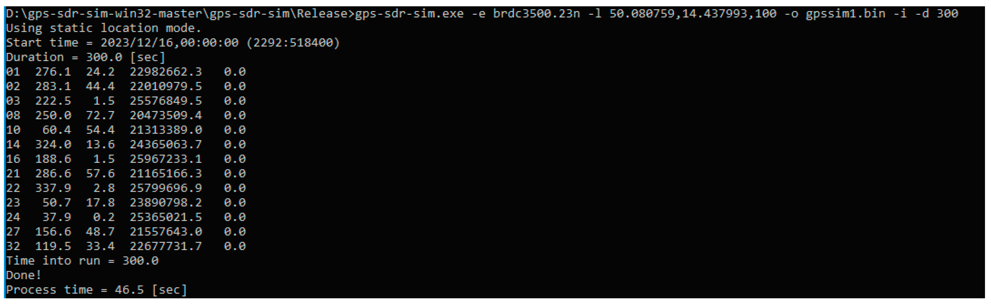
  • Signal generation: A GPS satellite constellation was specified through a GPS broadcast ephemeris file obtained from NASA. This file was processed to create a binary file for signal distribution using the “gps-sdr-sim” software Hack RF One.
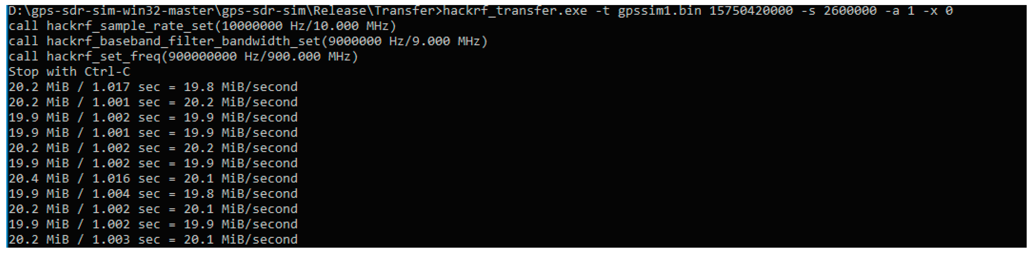
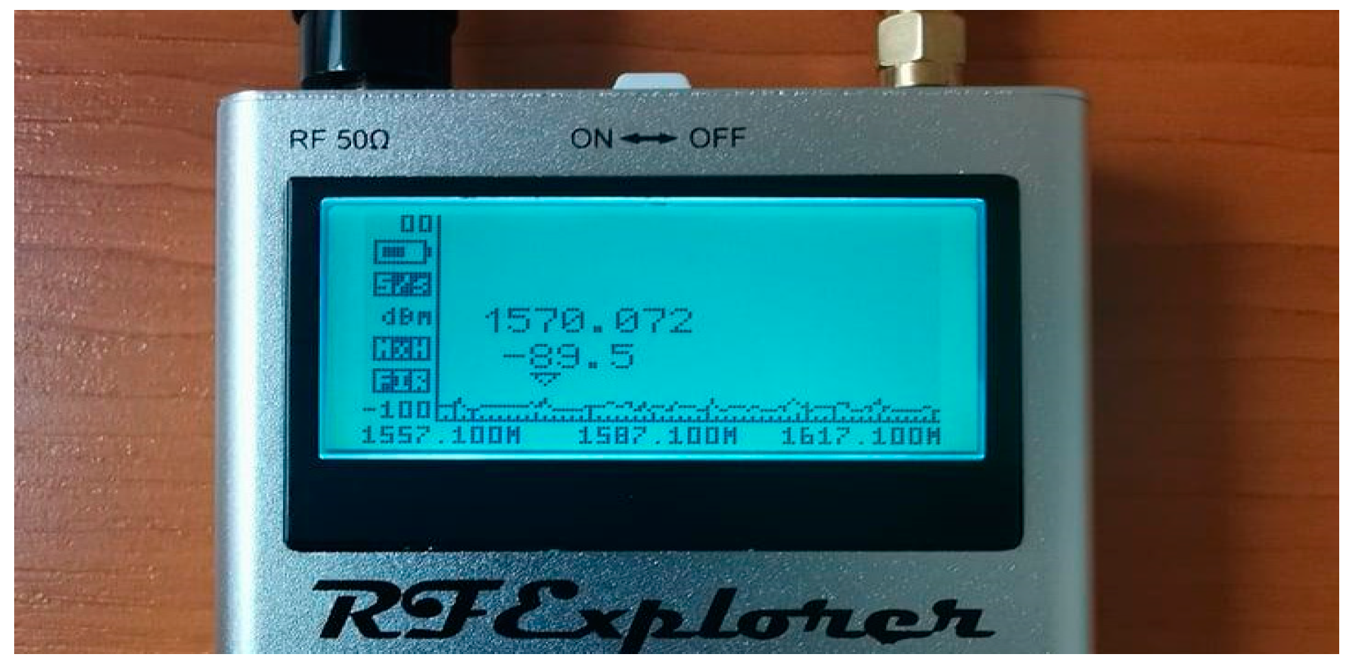
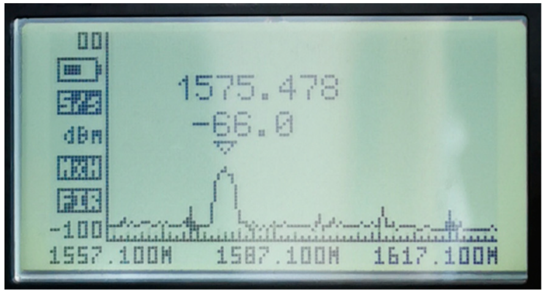
  • Signal transmission: The generated GPS signal was transmitted using the HackRF One at a specified frequency. The transmission process was observed and verified using a spectrum analyzer.
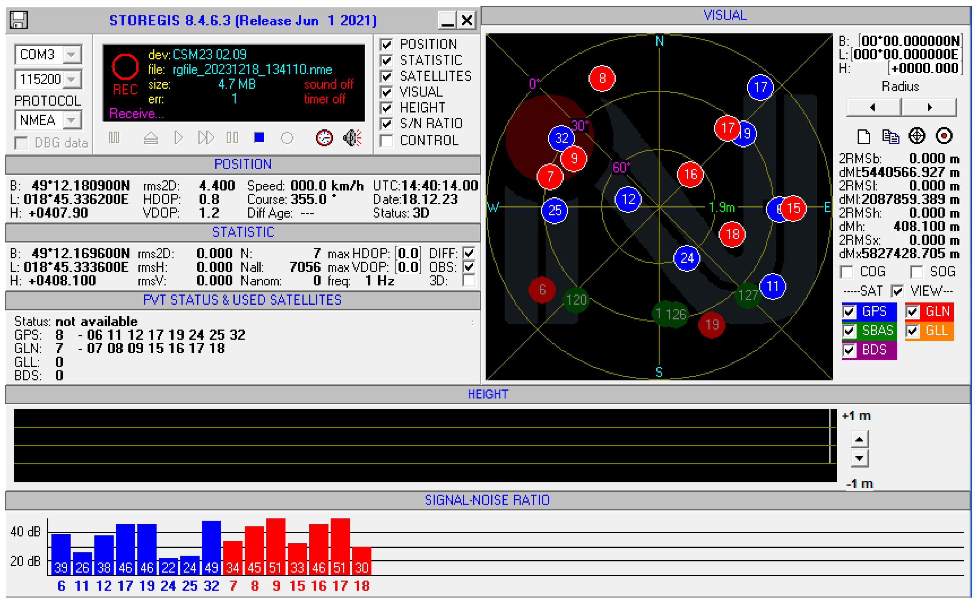
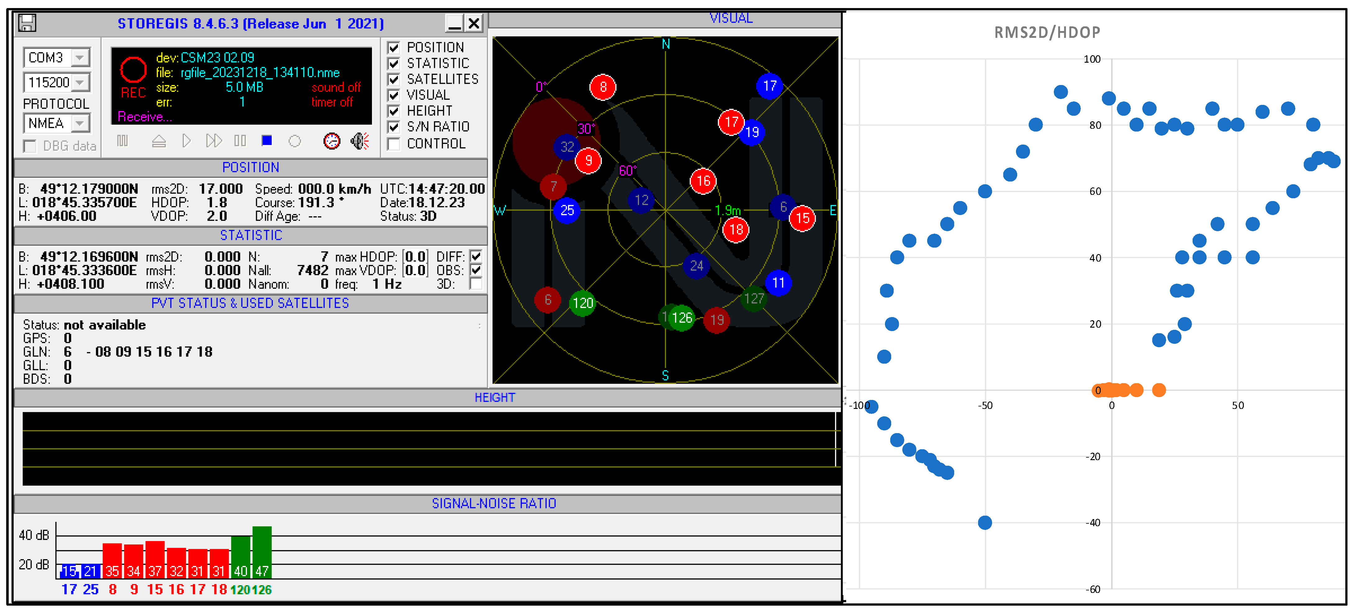
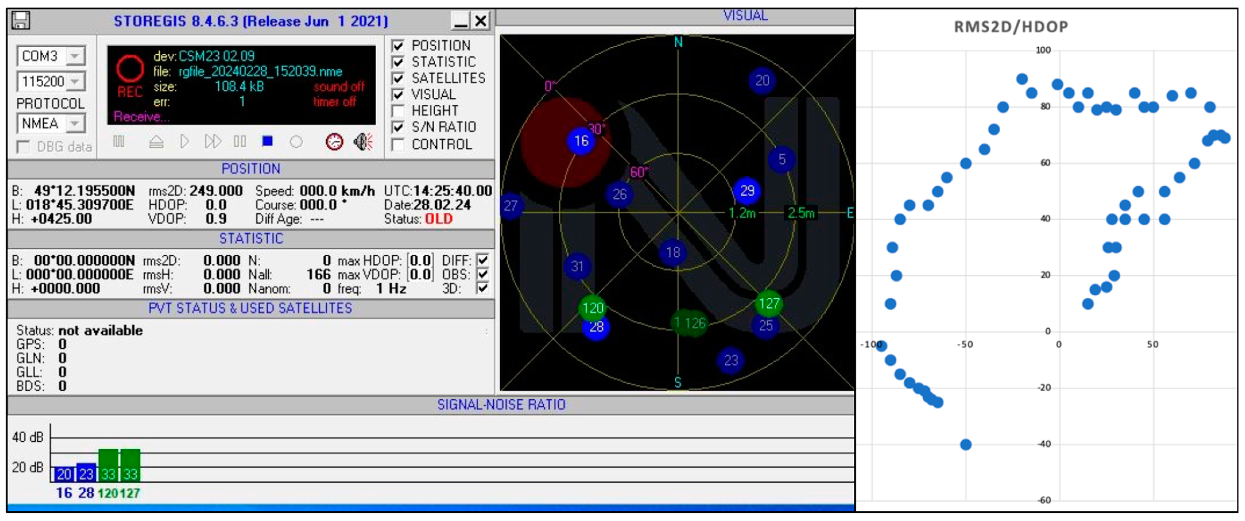
  • Signal reception and analysis: The transmitted signal was analyzed using an NV08C-CSM integrated satellite navigation receiver. Measurements of signal reception, including changes in course, accuracy measures (such as 2DRMS), and interference effects on the receiver, were documented and analyzed.
  • Assessment of interference power and distance: calculations and assessments were conducted to determine the interference power level, critical interference threshold, and maximum distance within which interference could disrupt the GNSS receiver.
  • Documentation and comparison: results obtained from the transmitted spoof signal were compared with reference measurements taken without the artificial signal to evaluate the impact on the receiver’s performance and accuracy.
Overall, the methodology consisted of configuring the SDR device (see Figure 2), generating and transmitting artificial signals, receiving and analyzing these signals using specialized equipment, and assessing their effects on the GNSS receiver. The procedures were systematic, aiming to simulate and evaluate the potential threat of generated interference in GNSS signal reception and navigation systems.
Since the concern was focused on simplicity of generating and transmitting artificial spoof signal, the Windows operating system was chosen. Even though the chosen SDR, HackRF One, is a very reliable device in the selected price category, it is not precise enough to sufficiently spoof the GPS signal, so it was necessary to install the external TCXO, which improves the performance of SDR. After installing the TCXO into the HackRF One, it is important to determine if those two components are cooperating between each other. The verification can be performed by writing following command into Command Prompt: “hackrf_debug -i5351c -n 0 -r”. An unsuccessful response would indicate a lack of cooperation, depicted in Figure 3, while successful cooperation would be demonstrated in Figure 4.
In the second measurement, we performed without an active GLONASS receiver. This configuration allowed us to verify the ability to recover the receiver and determine the position after signal recovery.

3. Results

3.1. Generation of GPS Signal

Once the setup is complete, it is possible to generate a GPS signal, specified by the GPS satellite constellation through a GPS broadcast ephemeris file. The daily GPS broadcast ephemeris file (brdc) is a merge of the individual site navigation files into one. All the necessary information were found on the NASA webpage [56]. After downloading the most recent file, the binary file is used for distributing signal created through command: “gps-sdr-sim -e brdc3500.23n -l 50.080759,14.437993,100”. The following list explains the individual commands:
  • “gps sdr-sim” is software, through which it is possible to connect the created binary file and distribute it through RTL-SDR HackRF One;
  • “-e <gps_nav>” is RINEX navigation file for GPS ephemerides;
  • “brdc3500.23n” is the most recent daily GPS broadcast ephemeris file published by NASA on the daily basis;
  • “-l <location>” are latitudinal, longitudinal and height coordinates (static mode), e.g., 50.080759,14.437993,100.
In Figure 5, it is possible to see the process of creating the binary file after entering the desired value of GPS location. For the needs of this paper, the authors have entered the GPS location of Prague.
After the creation of the complete binary file, the transmission of the spoof signal becomes feasible (see Figure 6). Initiating the transmission involves executing the following command: “hackrf_transfer -t gpssim.bin -f 1575420000 -s 2600000 -a 1 -x 0.”
The transmitting signal of 1575.42 MHz is possible to check with a spectrum analyzer from RF Explorer. In Figure 7, it is possible to see spectrum around 1575 MHz when no signal is distributed.
In Figure 8, the selected signal is being transmitted via the SDR HackRF One equipped with an external TCXO. The spectrum analyzer reveals that this signal is indeed propagating at a strength of −66.0 dB.
Even though the spectrum analyzer catches the spoof signal, it is unknown how the devices will respond on this signal. For checking the spoof signal, the NV08C-CSM integrated satellite navigation GPS, GLONASS, Galileo and SBAS receiver was used. In Figure 9, it is possible to see the actual visible satellites from all mentioned systems whose signals can reach in normal conditions. Reference measurement was performed in normal conditions (Figure 9) without any artificially generated signal.
After reference measurement and checking the visibility of the satellites, it is possible to run the generated binary file with desired frequency and location. After few seconds of running, the NV08C-CSM receiver is not able to catch any of the GPS satellites, as shown in Figure 10. Even though the position has not been changed from the desired and pre-programmed one, in other words spoofed, the power of transmitter was high enough to jam the GPS receiver. Since we have been transmitting the GPS L1 band of frequency 1575.42 MHz, it is still possible for receiver to catch the signal from GLONASS system, since it runs on a different frequency. Another change that has happened during the propagation of spoofed signal is change in the course. During the reference measurement, the course has fixed value of 355.0°, but during the transmitting of spoofed signal, the course changed to value of 191.3°. After quitting the transmitting of spoofed signal, the value returned to original value.
In Figure 10, the scatter plot visualizes the course of measurements during the transmission of a spoof signal. It includes a scatter plot visualization that demonstrates the impact of transmitting a spoof signal on the accuracy of the GPS receiver. The plot shows the deviation in course and the RMS2D values, which indicate the error in position determination caused by the transmitted spoof signal. The highest RMS2D value in Figure 9 is approximately four times higher than in the reference measurement, highlighting the impact of the interference on GPS signal reception.
In the second measurement we performed, GLONASS signal reception and SBAS satellite extension were turned off. With this configuration, we verified the ability to recover the receiver and determine the position after signal recovery. In Figure 11, the scatter plot visualizes the course of measurements during the transmission of a spoof signal without an active GLONASS receiver. The plot shows the deviation in course and the RMS2D values, which indicate the error in position determination caused by the transmitted spoof signal under these specific conditions. The highest RMS2D value in Figure 11 is notably higher compared to the reference measurement, indicating a significant increase in error due to the absence of an active GLONASS receiver during the transmission of the spoof signal.
The RMS2D value is notably intriguing. As depicted in Figure 10, the highest RMS2D value is 17.0, which means that it is approximately four times higher than in the reference measurement. In the second case of measurement (Figure 11), the highest RMS2D value is 249.0, which means that it is approximately 57 times higher than in the reference measurement. However, this error is primarily caused by the complete loss of the GPS L1C signal, without the reference of another satellite navigation systems. This measure unit can be defined as 2DRMS as well, and means “Twice Distance Root Mean Square Error”. Even though the 2DRMS is measurement in 2D space, to be concrete in horizontal space, the “2D” in this abbreviation stands for “Twice Distance”. The key factor is the accuracy of receiving signal. There are many accuracy measures, and each of them are used for specific systems, since the errors of position coordinates determined using a GPS or GLONASS unit are not constant, they vary statistically. When observing the reported position of a stationary receiving system over time, it becomes evident that it fluctuates or deviates. Converting these moving points into a visual representation would result in a scatter plot. The position is essentially three-dimensional; however, it can be analyzed either in horizontal or vertical accuracy individually. In Table 2 the most used types of measure methods are listed, including its dimensions, precision probability and typical usage.
The most used types of measure methods include the root mean square, twice distance rms, circular error probable, horizontal 95 percent accuracy and spherical error probable. The root mean square is defined as the square root of the average of the squared errors. The twice distance rms is defined as twice the root mean square of the horizontal errors. The circular error probable is a circle’s radius, centered at the true antenna position, containing 50 percent of the points in the horizontal scatter plot. The horizontal 95 percent accuracy is defined as a circle’s radius, centered at the true antenna position, containing 95 percent of the points in the horizontal scatter plot. The spherical error probable is a sphere’s radius, centered at the true antenna position, containing 50 percent of the points in the three-dimensional scatter plot. Each of those measurement methods has its own advantages and disadvantages, and precision probability [49].
Table 3 provides a comparison of the practical test results on UAV GNSS receivers with various configurations, along with whether they include jamming/spoofing detection capabilities. Each column represents a different UAV model, and the row detail the GNSS receiver configuration and the presence of jamming/spoofing detection features, denoted as “Yes” or “No”.
This measurement fulfills the objective outlined in the research above by providing specific data and insights into how different types of GNSS receivers respond to signal interference and manipulation. These insights could be used to assess the level of security and reliability of UAVs when exposed to artificial interferences, as well as to develop measures to enhance resilience against them. Overall, this measurement contributes to a better understanding of the potential risks and challenges associated with using drones in environments where GNSS signals may be affected by interference.
The new generation of GNSS receivers is already resilient and capable of detecting interference under certain limiting conditions, with the latest firmware upgrades also addressing spoofing. However, the question remains whether we can ensure GNSS signal resilience against interference in all circumstances in the future. This goal is challenging, as the technological landscape of signal interference continues to evolve. It is crucial to continue innovating and researching to create and implement effective methods for protecting GNSS signals. This includes not only improving the receivers themselves, but also developing better algorithms and protocols for detecting and mitigating interference, as well as collaborating with other technological sectors to create more complex and robust systems.
Securing GNSS signals against interference will require not only technical innovations, but also international cooperation and appropriate legal and regulatory measures. It is a challenge that we must collectively address to ensure reliable and secure navigation using GNSS in all possible scenarios.

3.2. Power and Distance of Interfering Signal Assessment

The ratio of Jamming to Signal can be calculated by following formula:
J S = J R S R ( dB ) ,
where JR is the value of the received power of the interfering signal (dBm or dBW) and SR is the value of the received power of the satellite signal (dBm or dBW) [49].
The critical value (J/S)C, which represents a certain interference threshold at which the GNSS receiver is unable to perform its function, ranges from about 37 to 60 dB, as found by countless experimental measurements, the results of which have been published in multiple studies [49]. The value of (J/S)C varies depending on the type of GNSS receiver and the type of interfering signal used. Interference from white noise or narrowband signals must be transmitted with much higher power in order to achieve complete interference, thus higher values (J/S)C correspond to this. A broadband interference signal (such as a chirp signal) requires lower power, and thus a value (J/S)C corresponds to lower values. The calculation of the critical range assuming propagation in free space is based on the equation:
P r d = P t G t G r λ 2 ( 4 π ) 2 d 2 L   ( W ) ,
where Pr is the received signal power at a distance d from the transmitter, Pt is the power of the transmitted signal, Gt and Gr are the gain of the transmitting or receiving antenna, λ is the wavelength of the transmitted signal and L represents losses in the receiver that do not affect propagation [49].
GNSS signals are usually available on Earth with a power of approximately −125 dBm. The specification for GPS signals at frequencies L1 and L2 states that the minimum received level for users on Earth is −158.5 dBW (−128.5 dBm) for the C/A-code on L1, and −160 dBW (−130 dBm) for the Pr code on L2 [36,51,57,58]. The signal strength is further affected by the elevation of the satellite and the influence of the troposphere and ionosphere. It follows from the above that the order level of the interfering signal, which would cause the interference of the already captured GNSS signal, is at a value of −80 dBm and higher [59]. The specific value will fluctuate by about 25 dB, depending on the polarization of the antenna, the bandwidth with which the receiver works, and the sensitivity setting of the receiver [60,61]. Losses in the propagation of an electromagnetic wave through space LFSPL is represented by the following equation:
L F S P L = ( 4 π d λ ) 2 = ( 4 π d f c ) 2 ,
where LFSPL are losses in the propagation of an electromagnetic wave through free space, d is the distance between the antenna of the interfering signal transmitter and the antenna of the GNSS signal receiver, f is the interference frequency, c is the speed of light and λ is the wavelength of the transmitted signal [61]. If we consider the basic model of electromagnetic wave propagation through free space (3), the attenuation of the environment is as follows (Table 4).
Rewriting Equation (2) into a form for substituting variables in dB, we obtain [62]:
P r = P t + G t + G r L L F S P L = P t + G t + G r L 20 l o g 10 4 π d f c   d B W ,
If we consider negligible losses in the receiver, and if we consider the receiving antenna as isotropic and use the value of the effective radiated power EIRP, then we can rewrite Formula (4) as follows:
P r = E I R P t 20   l o g 10 ( 4 π d f c )   ( d B W ) ,
Once we know the power level of the GNSS signal on the Earth’s surface (see Table 5) and assume knowledge of the critical value (J/S)C, then we can calculate from Equation (2) what will be the limit power JC of the interfering signal at the GNSS receiver, which disables the correct function of the receiver [62]. Substituting into Equation (5) and expressing the distance d from the formula, we obtain the maximum distance of the jammer dmax, in which the jammer can disturb the GNSS receiver:
d m a x = c 4 π f 10 E I R P t J c 20   ( m )

3.3. Detection and Mitigation of Spoofing

Many countermeasures based on receivers against spoofing attacks share common principles with interference detection and mitigation techniques. The primary distinction is that anti-spoofing measures can also be integrated at the system level of GNSS through signal design.
User-level techniques can be categorized based on their capabilities. The following segments distinguish various stages of anti-spoofing techniques, ranging from detection to mitigation.
Pre-correlation techniques are notably less effective in cases of spoofing, as spoofing signals inherently match the power levels of authentic satellite signals, and user conditions (such as channel model) may obscure a spoofer’s detection capabilities. However, proposed methods like pre-correlation detection techniques based on the generalized likelihood ratio test (GLRT) from [63] can be valuable when facing unsophisticated spoofing attacks that mask the impact of user channel conditions and receiver processing on the null hypothesis formulation.
Another intriguing spoofing detection concept is presented in [64], introducing a clock monitoring-based detection scheme that exploits the common projection of relative delays from all spoofed satellites onto the user receiver’s clock solution. Such techniques require well-characterized, calibrated receiver clocks and are more suitable for unsophisticated spoofers.
Multipath detection techniques serve as a defensive measure potentially applicable for spoofing detection. Signal quality monitoring (SQM) algorithms utilize a test statistic derived from correlation values at different spacings and the autocorrelation function. While they assume that signal and noise are solely present in the channel, their effectiveness is conditionally limited, particularly in the presence of multipath.
Additional DSP-based spoofing detection techniques have explored the spectral structure of GNSS signals, focusing on concentrating signal spectral lines through Doppler removal and utilizing the estimated variance of noise-only parts of the spectrum as a detection metric compared to spoof-free conditions [65]. Time-frequency analysis employing multiresolution algorithms has also been employed to discern the relative Doppler of additional (spoofing) signals from line-of-sight signals via eigen-decomposition of the autocorrelation matrix. This approach also offers mitigation capabilities, where a notch filter can be applied to eliminate spoofed signals post-classification through Doppler estimation.
A method for authenticating and distinguishing between authentic and spoofed signals is introduced in [66], leveraging the capabilities of a kinematic user to identify and classify spoofing signals based on correlations in channel gain and Doppler among the spoofed satellites. Subsequently, Ref. [67] proposes a technique for mitigating spoofing signals by systematically eliminating them from the received signal. This approach assumes independent tracking of authentic and spoofed signals and that the spoofer does not adjust for the user’s motion relative to the spoofer’s position.
Another approach utilizes correlation of carrier phase measurements among authentic and spoofed satellites, employing either an articulating [68] or a dual antenna [69,70] architecture. As depicted in Figure 9, the carrier phases of spoofed satellites exhibit high correlation due to identical direction of arrival (DOA) for all satellites. While this method is robust, it entails higher cost and complexity and is limited to detection alone.
In general, the effectiveness of any spoofing detection, characterization, and discrimination algorithm may be hindered in complex multipath environments and when confronted with highly sophisticated spoofers who adjust for relative user-spoofer dynamics or introduce some level of independence among spoofing signals.
In conclusion, it is crucial to evaluate the capabilities of the discussed techniques across various environments and use cases, as most validation has occurred in open spaces or airfields. Additionally, receiver-based methods should be examined for different spoofing scenarios, considering their performance relative to spoofing sophistication and for diverse receiver architectures. For instance, open-loop architectures may lack the ability to utilize carrier phase measurements.
Furthermore, the performance analysis of these techniques, either individually or in combination, should be aligned with key metrics and user-level requirements for each specific case and application. For example, a technique with high detection probability might also entail a longer detection latency, allowing a spoofer to potentially disrupt the receiver’s tracking. Given the multitude of factors to consider with user-level techniques, the GNSS community has turned to system-level approaches as a more comprehensive solution against spoofing.
In summary, Table 6 outlines the varying capabilities of spoofing detection and mitigation techniques and their suitability levels at the receiver level.

4. Discussion

As can be seen, the used device, HackRF One, along with the necessary equipment, can be used for generating any desired signal thus, through this device, any frequency can be jammed or spoofed, including, for instance, the GLONASS frequency. From the measurements, artificial spoof signal created by authors have been strong enough to jam the GPS receiver in a way that it was not possible for receiver to catch any of GPS satellites. Also, the 2DRMS accuracy was significantly decreased during the measurement with spoof signal. During the reference measurement when no artificial signal was transmitted, the value of 2 drms was 2.4 which is according to the table value of accuracy more than 97%. However, when the generated spoof signal was transmitted, two major events happened. The 2drms was significantly decreased (by more 76.6%), since the measured value of 2 drms reached 20.8. The other thing was the change in the course. The course had a stable value of 355.0° during the reference measurement; however, during spoof signal measurement, the value radically changed to 191.3°, meaning, the course turned almost precisely other way around.
Table 7 presents the probabilities associated with drms (root mean square) and 2 drms (twice distance root means square error) for various standard deviations (σyx). Table 5 showcases the relationship between the standard deviations and the probabilities associated with both drms and 2 drms and provides insights into the statistical likelihoods associated with the drms and 2 drms values, based on the standard deviations in the positioning system. It shows how different standard deviation ratios impact the probabilities of both drms and 2 drms, which are essential accuracy measures used in evaluating the precision of positioning systems.
The research into the impact of the HackRF One, equipped with an external TCXO, on the safety and functionality of UAVs through the generation of artificial interference in the GNSS signal has yielded valuable insights. The results highlight the susceptibility of UAVs to the artificial interference generated by the HackRF One, leading to potential safety and operational risks. The observed failure of GPS receivers and the significant decrease in accuracy measures during spoofed signal transmission emphasize the need for robust countermeasures to mitigate the identified threats.
Furthermore, the study demonstrates the practical implications of such interference in real-world scenarios, where UAVs rely heavily on GNSS signals for navigation and positioning. The discussion delves into the implications of these findings for the wider UAV industry, emphasizing the importance of developing advanced detection mechanisms and resilient technologies to protect against unauthorized interference.
More than 12 years ago already, researchers at the University of Texas at Austin demonstrated the vulnerability of civilian UAVs to GPS spoofing attacks, followed by a similar demonstration for FAA and DHS officials [71]. Subsequently, in the summer of 2013, the University of Texas at Austin team successfully spoofed a position private yacht using their technology [72]. At DefCon 2015, Qihoo 360 researchers presented a low-cost GPS spoofer capable of falsifying smartphone and in-car navigation system locations [73]. The researchers at university and experts from FAA and DHS highlighted the broader risks of insecure civil GPS technology to critical infrastructure and recommended measures to enhance spoof resistance, including requiring spoof-resistant navigation systems for UAVs and critical GNSS-based systems.
While the HackRF One showcased its adaptability and functionality for various applications, including the generation of artificial interference, our study serves as a starting point for further research. Future investigations should explore additional experiments with diverse signals, considering the evolving landscape of jamming and spoofing technologies. Additionally, integrating machine learning algorithms and artificial intelligence with SDR technologies could enhance the ability to distinguish between legitimate and malicious signals, contributing to a more secure UAV environment.

5. Conclusions

In conclusion, the escalating use of UAVs in airspace presents a significant safety concern due to the ease of jamming or spoofing signals. This vulnerability, particularly in the GNSS, poses a substantial threat to general aviation operations. Given the increasing reliance on UAVs for a multitude of applications, including surveillance, logistics, and beyond, the need for robust countermeasures to protect against potential disruptions caused by spoofing or jamming signals becomes paramount.
This research primarily focused on evaluating the impact of the SDR HackRF One on UAV safety. By demonstrating the device’s ability to generate artificial interference capable of disrupting the GPS receiver’s functionality, our research underscores the potential risks associated with such interference in real-world scenarios. The findings revealed that transmitting an artificial spoof GPS signal led to the failure of the GPS receiver in capturing any visible satellites. This failure was substantial and hazardous, indicating a potential risk if encountered in actual operational conditions. The methodology systematically involved configuring the SDR device, generating and transmitting signals, analyzing their effects on the GNSS receiver, and assessing interference systematically. Notably, deviations in course and accuracy measures were evident when encountering interference, with significant changes observed in course values and accuracy measures like RMS2D. In a second measurement without an active GLONASS receiver, significant deviations were noted in course values, and a notably higher RMS2D value compared to the reference measurement. The RMS2D value was approximately 57 times higher due to the complete loss of GPS L1C signal without reference to another satellite navigation system. These results underscore the critical importance of considering different scenarios and configurations when assessing interference effects on GNSS receivers.
The implications of this research are critical in comprehending the vulnerabilities present in GNSS signals and the potential threats posed by unauthorized interference. Moreover, it emphasizes the necessity for robust countermeasures to safeguard UAV operations in airspace against potential disruptions caused by spoofing or jamming signals. While the HackRF One device showcased its adaptability and functionality for various applications related to UAV operations, its use in detecting spoofed GNSS signals signifies an added value in augmenting UAV safety measures within airspace. Future research should delve deeper into developing advanced detection mechanisms and resilient technologies to safeguard UAVs from emerging threats in the jamming and spoofing landscape.
Furthermore, the implementation of machine learning algorithms and artificial intelligence in conjunction with SDR technologies could enhance the ability to distinguish between legitimate and malicious signals, contributing to a more secure UAV environment. Research efforts should also focus on collaborative initiatives between industry stakeholders, regulatory bodies, and academia to formulate comprehensive guidelines and standards for UAV communication security. Addressing the challenges posed by potential interference requires a multidisciplinary approach that combines expertise in telecommunications, cybersecurity, and aeronautics. This collaborative effort is essential to stay ahead of adversaries seeking to exploit vulnerabilities in UAV communication systems. As technology continues to advance, it is important for the research community to remain proactive in devising innovative solutions to mitigate the risks associated with GNSS interference.

Author Contributions

Conceptualization, A.N., K.K., B.K. and A.N.S.; methodology, A.N., K.K., B.K. and A.N.S.; software, A.N. and B.K.; validation, A.N., K.K. and B.K.; formal analysis, K.K. and A.N.S.; investigation, A.N. and A.N.S.; resources, A.N., K.K., B.K. and A.N.S.; data curation, A.N. and B.K.; writing—original draft preparation, A.N. and K.K.; writing—review and editing, A.N., K.K., B.K. and A.N.S.; visualization, K.K., B.K. and A.N.S.; supervision, A.N.; project administration, A.N. and B.K.; funding acquisition, A.N. All authors have read and agreed to the published version of the manuscript.

Funding

This research received no external funding.

Data Availability Statement

Data are contained within the article.

Acknowledgments

The paper is an output of the project KEGA 040ŽU–4/2022 Transfer of progressive methods of education to the study program “Aircraft Maintenance Technology” and “Air Transport”.

Conflicts of Interest

The authors declare no conflicts of interest.

References

  1. Hoffman-Wellenhof, B.; Lichtenegger, H.; Wasle, E. GNSS-Global Navigation Satellite Systems: GPS, GLONASS, Galileo, and More; Springer and Science & Business Media: Berlin/Heidelberg, Germany, 2007; ISBN 978-3-211-73012-6. [Google Scholar]
  2. Radočaj, D.; Plaščak, I.; Jurišić, M. Global navigation satellite systems as state-of-the-art solutions in precision agriculture: A review of studies indexed in the web of science. Agriculture 2023, 13, 1417. [Google Scholar] [CrossRef]
  3. Marz, S.; Schlicht, A.; Hugentobler, U. Toward a Geodesy and Time Reference in Space (GETRIS): A Study of Apparent Satellite Clocks of a Future GNSS Satellite Constellation. Geosciences 2023, 13, 173. [Google Scholar] [CrossRef]
  4. Telli, K.; Kraa, O.; Himeur, Y.; Ouamane, A.; Boumehraz, M.; Atalla, S.; Mansoor, W. A comprehensive review of recent research trends on unmanned aerial vehicles (uavs). Systems 2023, 11, 400. [Google Scholar] [CrossRef]
  5. Budiyono, A.; Higashino, S.I. A Review of the Latest Innovations in UAV Technology. J. Instrum. Autom. Syst. 2023, 10, 7–16. [Google Scholar] [CrossRef]
  6. Milota, J. Software Radios: Survey, Critical Evaluation and Future Directions. IEEE Aerosp. Electron. Syst. Mag. 1993, 8, 25–36. [Google Scholar] [CrossRef]
  7. Del Barrio, A.A.; Manzano, J.P.; Maroto, V.M.; Villarín, Á.; Pagán, J.; Zapater, M.; Ayala, J.; Hermida, R. HackRF+ GNU Radio: A software-defined radio to teach communication theory. Int. J. Electr. Eng. Educ. 2023, 60, 23–40. [Google Scholar] [CrossRef]
  8. Mori, S.; Mizutani, K.; Harada, H. Software-Defined Radio-Based 5G Physical Layer Experimental Platform for Highly Mobile Environments. IEEE Open J. Veh. Technol. 2023, 4, 230–240. [Google Scholar] [CrossRef]
  9. Hrúz, M.; Bugaj, M.; Novák, A.; Kandera, B.; Badánik, B. The Use of UAV with Infrared Camera and RFID for Airframe Condition Monitoring. Appl. Sci. 2021, 11, 3737. [Google Scholar] [CrossRef]
  10. Kakkavas, G.; Tsitseklis, K.; Karyotis, V.; Papavassiliou, S. A software defined radio cross-layer resource allocation approach for cognitive radio networks: From theory to practice. IEEE Trans. Cogn. Commun. Netw. 2020, 6, 740–755. [Google Scholar] [CrossRef]
  11. Bargarai, F.; Abdulazeez, A.; Tiryaki, V.; Zeebaree, D. Management of wireless communication systems using artificial intelligence-based software defined radio. IJIM 2020, 14, 107–133. [Google Scholar] [CrossRef]
  12. Kumar, B.P.; Paidimarry, C.S. Improved real time GPS RF data capturing for GNSS SDR applications. Gyroscopy Navig. 2020, 11, 59–67. [Google Scholar] [CrossRef]
  13. Flak, P. Drone detection sensor with continuous 2.4 GHz ISM band coverage based on cost-effective SDR platform. IEEE Access 2021, 9, 114574–114586. [Google Scholar] [CrossRef]
  14. Aboelazm, M.A. Design and implementation of analog modulated signals radio monitoring receiver based on SDR technology. J. Inf. Hiding Multimed. Signal Process. 2022, 13, 64–77. [Google Scholar]
  15. Woh, M.; Lin, Y.; Seo, S.; Mahlke, S.; Mudge, T.; Chakrabarti, C.; Bruce, R.; Kershaw, D.; Reid, A.; Wilder, M.; et al. From SODA to scotch: The evolution of a wireless baseband processor. In Proceedings of the 2008 41st IEEE/ACM International Symposium on Microarchitecture, Lake Como, Italy, 8–12 November 2008; pp. 152–163. [Google Scholar] [CrossRef]
  16. Zhang, Z.; Zhan, X.; Xu, H. Development and Validation of a Low-cost GPS Spoofing Simulator. J. Aeronaut. Astronaut. Aviat. 2014, 46, 78–86. [Google Scholar] [CrossRef]
  17. Dovis, F. GNSS Interference Threats and Countermeasures; Artech House: Norwood, MA, USA, 2015; ISBN 978-1-60807-810-3. [Google Scholar]
  18. Broumandan, A.; Jafarnia-Jahromi, A.; Daneshmand, S.; Lachapelle, G. Overview of spatial processing approaches for GNSS structural interference detection and mitigation. Proc. IEEE 2016, 104, 1246–1257. [Google Scholar] [CrossRef]
  19. De Wilde, W.; Cuypers, G.; Sleewaegen, J.M.; Deurloo, R.; Bougard, B. GNSS interference in unmanned aerial systems. In Proceedings of the 29th International Technical Meeting of the Satellite Division of the Institute of Navigation (ION GNSS+ 2016), Oregon, Portland, 12–16 September 2016; pp. 1465–1476. [Google Scholar] [CrossRef]
  20. Motella, B.; Savasta, S.; Margaria, D.; Dovis, F. Method for assessing the interference impact on GNSS receivers. IEEE Trans. Aerosp. Electron. Syst. 2011, 47, 1416–1432. [Google Scholar] [CrossRef]
  21. Qiao, J.; Lu, Z.; Lin, B.; Song, J.; Xiao, Z.; Wang, Z.; Li, B. A survey of GNSS interference monitoring technologies. Front. Phys. 2023, 11, 1133316. [Google Scholar] [CrossRef]
  22. Silva Lorraine, K.J.; Ramarakula, M. A comprehensive survey on GNSS interferences and the application of neural networks for anti-jamming. IETE J. Res. 2023, 69, 4286–4305. [Google Scholar] [CrossRef]
  23. Sun, K.; Zhang, T. A new GNSS interference detection method based on rearranged wavelet–hough transform. Sensors 2021, 21, 1714. [Google Scholar] [CrossRef] [PubMed]
  24. Gadgets, G.S. HackRF One-Great Scott Gadgets. 2023. Available online: https://greatscottgadgets.com/hackrf/one (accessed on 30 November 2023).
  25. Elghamrawy, H.; Karaim, M.; Tamazin, M.; Noureldin, A. Experimental evaluation of the impact of different types of jamming signals on commercial GNSS receivers. Appl. Sci. 2020, 10, 4240. [Google Scholar] [CrossRef]
  26. McGraw, G.A.; Groves, P.D.; Ashman, B.W. Robust positioning in the presence of multipath and NLOS GNSS signals. In Position, Navigation, and Timing Technologies in the 21st Century: Integrated Satellite Navigation, Sensor Systems, and Civil Applications; John Wiley & Sons: Hoboken, NJ, USA, 2020; Volume 1, pp. 551–589. [Google Scholar] [CrossRef]
  27. Ding, M.; Chen, W.; Ding, W. Performance analysis of a normal GNSS receiver model under different types of jamming signals. Measurement 2023, 214, 112786. [Google Scholar] [CrossRef]
  28. ICAO. Doc 8071-Manual on Testing of Radio Navigation Aids. Volume II, Testing of Satellite Based Radio Navigation Aids, 5th ed.; International Civil Aviation Organization: Montreal, QC, Canada, 2006. [Google Scholar]
  29. Gao, G.X.; Sgammini, M.; Lu, M.; Kubo, N. Protecting GNSS receivers from jamming and interference. Proc. IEEE 2016, 104, 1327–1338. [Google Scholar] [CrossRef]
  30. Li, Y.; Feng, B.; Zhang, W. Mutual Interference Mitigation of Millimeter-Wave Radar Based on Variational Mode Decomposition and Signal Reconstruction. Remote Sens. 2023, 15, 557. [Google Scholar] [CrossRef]
  31. Li, A.; Spano, D.; Krivochiza, J.; Domouchtsidis, S.; Tsinos, C.G.; Masouros, C.; Chatzinotas, S.; Li, Y.; Vucetic, B.; Ottersten, B. A tutorial on interference exploitation via symbol-level precoding: Overview, state-of-the-art and future directions. IEEE Commun. Surv. Tutor. 2020, 22, 796–839. [Google Scholar] [CrossRef]
  32. Boyer, M.; Bouyer, L.; Roy, J.S.; Campeau-Lecours, A. Reducing Noise, Artifacts and Interference in Single-Channel EMG Signals: A Review. Sensors 2023, 23, 2927. [Google Scholar] [CrossRef] [PubMed]
  33. Ru, Z.; Moseley, N.A.; Klumperink, E.A.; Nauta, B. Digitally enhanced software-defined radio receiver robust to out-of-band interference. IEEE J. Solid-State Circuits 2009, 44, 3359–3375. [Google Scholar] [CrossRef]
  34. Rahman, M.; Haider, A.; Naghshvarianjahromi, M. A systematic methodology for the time-domain ringing reduction in UWB band-notched antennas. IEEE Antennas Wirel. Propag. Lett. 2020, 19, 482–486. [Google Scholar] [CrossRef]
  35. Osechas, O.; Fohlmeister, F.; Dautermann, T.; Felux, M. Impact of GNSS-band radio interference on operational avionics. NAVIGATION J. Inst. Navig. 2022, 69, navi.516. [Google Scholar] [CrossRef]
  36. Le Roy, F.; Roland, C.; Le Jeune, D.; Diquet, J.P. Risk assessment of SDR-based attacks with UAVs. In Proceedings of the 16th International Symposium on Wireless Communication Systems, Oulu, Finland, 27–30 August 2019; pp. 222–226. [Google Scholar] [CrossRef]
  37. Huang, L.; Lu, Z.; Xiao, Z.; Ren, C.; Song, J.; Li, B. Suppression of jammer multipath in GNSS antenna array receiver. Remote Sens. 2022, 14, 350. [Google Scholar] [CrossRef]
  38. Su, X.L.; Zhan, X.; Tu, J. GNSS Constellation Integrity Evaluation Based on Quality Control. J. Aeronaut. Astronaut. Aviat. 2016, 48, 37–46. [Google Scholar] [CrossRef]
  39. Spens, N.; Lee, D.K.; Nedelkov, F.; Akos, D. Detecting GNSS jamming and spoofing on Android devices. NAVIGATION J. Inst. Navig. 2022, 69, navi.537. [Google Scholar] [CrossRef]
  40. Sharifi-Tehrani, O.; Sabahi, M.F.; Danaee, M.R. Low-complexity framework for GNSS jamming and spoofing detection on moving platforms. IET Radar Sonar Navig. 2020, 14, 2027–2038. [Google Scholar] [CrossRef]
  41. Falletti, E.; Gamba, M.T.; Pini, M. Design and analysis of activation strategies for adaptive notch filters to suppress GNSS jamming. IEEE Trans. Aerosp. Electron. Syst. 2020, 56, 3718–3734. [Google Scholar] [CrossRef]
  42. Bažec, M.; Dimc, F.; Pavlovčič-Prešeren, P. Evaluating the vulnerability of several geodetic GNSS receivers under chirp signal L1/E1 jamming. Sensors 2020, 20, 814. [Google Scholar] [CrossRef] [PubMed]
  43. Zhang, J.; Cui, X.; Xu, H.; Lu, M. A two-stage interference suppression scheme based on antenna array for GNSS jamming and spoofing. Sensors 2019, 19, 3870. [Google Scholar] [CrossRef] [PubMed]
  44. Li, J.; Zhu, X.; Ouyang, M.; Li, W.; Chen, Z.; Fu, Q. GNSS spoofing jamming detection based on generative adversarial network. IEEE Sens. J. 2021, 21, 22823–22832. [Google Scholar] [CrossRef]
  45. Meng, L.; Yang, L.; Yang, W.; Zhang, L. A survey of GNSS spoofing and anti-spoofing technology. Remote Sens. 2022, 14, 4826. [Google Scholar] [CrossRef]
  46. Khan, S.Z.; Mohsin, M.; Iqbal, W. On GPS spoofing of aerial platforms: A review of threats, challenges, methodologies, and future research directions. PeerJ Comput. Sci. 2021, 7, e507. [Google Scholar] [CrossRef]
  47. Gaspar, J.; Ferreira, R.; Sebastião, P.; Souto, N. Capture of UAVs through GPS spoofing using low-cost SDR platforms. Wirel. Pers. Commun. 2020, 115, 2729–2754. [Google Scholar] [CrossRef]
  48. Haljaková, P.; Novák, A.; Žižka, J. Monitoring GNSS signal quality at Žilina airport. New Trends in Civil Aviation. In Proceedings of the 19th International Conference on New Trends in Civil Aviation, Prague, Czech Republic, 7–8 December 2017; pp. 289–293, ISBN 978-0-8153-7602-6. [Google Scholar]
  49. Van Rychlicki, M.; Kasprzyk, Z.; Rosiński, A. Analysis of accuracy and reliability of different types of GPS receivers. Sensors 2020, 20, 6498. [Google Scholar] [CrossRef]
  50. Gúcky, J.; Kováčiková, K.; Novák, A.; Bugaj, M. Analysis of the introduction of artificial intelligence in the control of UAV. In Proceedings of the New Trends in Aviation Development 2022, Novy Smokovec, Slovakia, 24–25 November 2022; pp. 67–70. [Google Scholar] [CrossRef]
  51. Kerns, A.K.; Shepard, D.P.; Bhatti, J.A.; Humphreys, T.E. Unmanned Aircraft Capture and Control via GPS Spoofing. J. Field Robot. 2014, 31, 617–636. [Google Scholar] [CrossRef]
  52. Terris-Gallego, R.; López-Salcedo, J.A.; Seco-Granados, G.; Fernandez-Hernandez, I. Preliminary Evaluation of Galileo ACAS using Existing E1-E6 Open Signals and a Low-Cost SDR Platform. In Proceedings of the 36th International Technical Meeting of the Satellite Division of the Institute of Navigation, Denver, CO, USA, 11–15 September 2023; pp. 1388–1402. [Google Scholar] [CrossRef]
  53. Nayfeh, M.; Li, Y.; Shamaileh, K.A.; Devabhaktuni, V.; Kaabouch, N. Machine Learning Modeling of GPS Features with Applications to UAV Location Spoofing Detection and Classification. Comput. Secur. 2023, 126, 103085. [Google Scholar] [CrossRef]
  54. Bi, S.; Li, K.; Hu, S.; Ni, W.; Wang, C.; Wang, X. Detection and Mitigation of Position Spoofing Attacks on Cooperative UAV Swarm Formations. IEEE Trans. Inf. Forensics Secur. 2024, 19, 1883–1895. [Google Scholar] [CrossRef]
  55. Martinez Quintero, J.C.; Estupiñan Cuesta, E.P.; Ramirez Lopez, L.J. A new method for the detection and identification of the replay attack on cars using SDR technology and classification algorithms. Results Eng. 2023, 19, 101243. [Google Scholar] [CrossRef]
  56. Broadcast Ephemeris Data. National Aeronautics and Space Administration. 2023. Available online: https://cddis.nasa.gov/Data_and_Derived_Products/GNSS/broadcast_ephemeris_data.html (accessed on 30 November 2023).
  57. Zhang, T.; Song, T.; Chen, D.; Zhang, T.; Zhuang, J. WiGrus: A WiFi-based gesture recognition system using software-defined radio. IEEE Access 2019, 7, 131102–131113. [Google Scholar] [CrossRef]
  58. Borio, D.; Gioia, C. Interference mitigation: Impact on GNSS timing. GPS Solut. 2021, 25, 37. [Google Scholar] [CrossRef]
  59. Morong, T.; Puričer, P.; Kovář, P. Study of the GNSS Jamming in Real Environment. Int. J. Electron. Telecommun. 2019, 65, 65–70. [Google Scholar] [CrossRef]
  60. Specht, M. The evaluation of the positioning accuracy of the EGNOS and DGPS systems based on the long-term measurements in the years 2006–2014. Pol. Cartogr. Rev. 2015, 47, 99–108. [Google Scholar] [CrossRef]
  61. Kalašová, A.; Faith, P.; Mikulski, J. Telematics applications, an important basis for improving the road safety. Tools Transp. Telemat. 2015, 531, 292–299. [Google Scholar] [CrossRef]
  62. Harre, I. Navgen-Calculation of Position Errors drms, 2drms, cep95 and of the Error Ellipse for p = 0.95. 2009. Available online: http://www.mar-it.com/NavGen/navgen.htm (accessed on 30 November 2023).
  63. Closas, P.; Arribas, J.; Fernandez-Prades, C. Spoofing detection by a reduced acquisition process. In Proceedings of the 2016 International Technical Meeting of The Institute of Navigation, Monterey, CA, USA, 25–28 January 2016; pp. 726–731. [Google Scholar] [CrossRef]
  64. Jafarnia-Jahromi, A.; Daneshmand, S.; Broumandan, A.; Nielsen, J.; Lachapelle, G. PVT solution authentication based on monitoring the clock state for a moving GNSS receiver. In Proceedings of the European Navigation Conference (ENC), Vienna, Austria, 23–25 April 2013. [Google Scholar]
  65. Jafarnia-Jahromi, A.; Broumandan, A.; Nielsen, J.; Lachapelle, G. Pre-despreading authenticity verification for GPS L1 C/A signals. Inst. Navig. 2014, 61, 1–11. [Google Scholar] [CrossRef]
  66. Broumandan, X.A.; Jafarnia-Jahromi, A.; Dehghanian, V.; Nielsen, J.; Lachapelle, G. GNSS spoofing detection in handheld receivers based on signal spatial correlation. In Proceedings of the IEEE/ION Position, Location and Navigation Symposium, Myrtle Beach, SC, USA, 23–26 April 2012; pp. 479–487. [Google Scholar]
  67. Broumandan, A.; Jafarnia-Jahromi, A.; Lachapelle, G. Spoofing detection, classification and cancelation (SDCC) receiver architecture for a moving GNSS receiver. GPS Solut. 2014, 19, 475–487. [Google Scholar] [CrossRef]
  68. Psiaki, X.M.L.; Powell, S.P.; O’Hanlon, B.W. GNSS spoofing detection using high-frequency antenna motion and carrier-phase data. In Proceedings of the 26th International Technical Meeting of the Satellite Division of the Institute of Navigation, Nashville, TN, USA, 16–20 September 2013; pp. 2949–2991. [Google Scholar]
  69. Psiaki, X.M.L.; OHanlon, B.W.; Powell, S.P.; Bhatti, J.A.; Wesson, K.D.; Schofield, T.E.; Humphreys, A. GNSS spoofing detection using two-antenna differential carrier phase. In Proceedings of the 27th International Technical Meeting of the Satellite Division of the Institute of Navigation, Tampa, FL, USA, 8–12 September 2014; pp. 2776–2800. [Google Scholar]
  70. Parro-Jimenez, M.; Ioannides, R.; Crisci, M.; Lopez-Salcedo, J.A. Signal-level integrity monitoring metric for robust GNSS receivers. In Proceedings of the 31st AIAA International Communications Satellite Systems Conference, Florence, Italy, 15–17 October 2013; p. 5613. [Google Scholar] [CrossRef]
  71. Roberts, X.J. Drones Vulnerable to Terrorist Hijacking, Researchers Say. 2012. Available online: http://www.foxnews.com/tech/2012/06/25/drones-vulnerable-to-terrorist-hijacking-researchers-say (accessed on 5 March 2024).
  72. UT News, The University of Texas at Austin. UT Austin Researchers Successfully Spoof an $80 Million Yacht at Sea. 2013. Available online: http://news.utexas.edu/2013/07/29/ut-austin-researchers-successfully-spoof-an-80-million-yacht-at-sea (accessed on 5 March 2024).
  73. Olson, P. Hacking a Phone’s GPS May Have Just Got Easier. Forbes. 2013. Available online: http://www.forbes.com/sites/parmyolson/2015/08/07/gps-spoofing-hackers-defcon/ (accessed on 5 March 2024).
Figure 1. Scheme of SDR.
Drones 08 00109 g001
Figure 2. Scheme of SDR configuration for GNSS signal transmitting.
Drones 08 00109 g002
Figure 3. Faulty response from SDR.
Drones 08 00109 g003
Figure 4. Correct answer from SDR.
Drones 08 00109 g004
Figure 5. Process of generating binary file.
Drones 08 00109 g005
Figure 6. Process of transmitting the spoof signal.
Drones 08 00109 g006
Figure 7. Spectral analysis of the spectrum interest.
Drones 08 00109 g007
Figure 8. Spectrum of interest while transmitting the spoof signal.
Drones 08 00109 g008
Figure 9. Course of a reference measurements.
Drones 08 00109 g009
Figure 10. Course of a measurements during transmitting of a spoof signal and scatter plot visualization.
Drones 08 00109 g010
Figure 11. Course of a measurements during transmitting of a spoof signal without an active GLONASS receiver and scatter plot visualization.
Drones 08 00109 g011
Table 1. Specifications of SDR devices [24,28,36].
DeviceFrequency RangeRF BandwidthSampling RateTransmit PowerPrice (EUR)
HackRF One1 MHz–6 GHz20 MHz20 MSPSMax 10 dBm280
BladeRF x-A447 MHz–6 GHz56 MHz61.44 MSPSMax 8 dBm540
ADALM-PLUTO325–3800 MHz20 MHz61.44 MSPS6 dBm230
Table 2. Accuracy measures and typical usage.
MeasureDimensionsProbability [%]Typical Usage
Root mean square [rms]168vertical
263–68horizontal
361–683D
Twice distance rms [2 drms]295–98horizontal
Circular error probable [CEP]250horizontal
Horizontal 95 percent accuracy [R95]295horizontal
Spherical error probable [SEP]3503D
Table 3. The practical test on UAV GNSS receiver with various configuration of GNSS receiver.
3DR IRIS+
Drones 08 00109 i001
Ublox NEO-6M-0 module, HMC5883L compass
Concurrent reception of up to single GNSS up to 5 Hz-navigation rate
To combat against jamming, NEO-M6 modules include monitor for continuous wave (narrowband) jammers/interference only. This monitor reports whether jamming has been detected or suspected by the receiver. The receiver monitors the background noise and looks for significant changes.HackRF One
Jamming/spoofing detection
Yes/No
Tarot 650 v 2.2
Drones 08 00109 i002
Ublox NEO-M8N module, IST8310 compass
Concurrent reception of up to 3 GNSS single GNSS up to 10 Hz–navigation rate
To combat against spoofing, NEO-M8N modules include spoofing detection measures to alert the host when signals appear to be suspicious. The receiver combines several checks on the received signals looking for inconsistencies across several parameters.HackRF One
Jamming/spoofing detection
Yes/Yes
DJI INSPIRE 2
Drones 08 00109 i003
Ublox M8 module, M8030 TK
Concurrent reception of up to 2 GNSS up to 10 Hz -navigation rate
To combat against spoofing, NEO-M8 modules include spoofing detection measures to alert the host when signals appear to be suspicious. The receiver combines several checks on the received signals, looking for inconsistencies across several parameters.HackRF One
Jamming/spoofing detection
Yes/Yes
SKY HUNTER
Drones 08 00109 i004
MATEKSYS M8Q-5883
Concurrent reception of up to 2 GNSS up to 10 Hz, single GNSS up to 18 Hz–navigation rate
To combat against spoofing, NEO-M8Q modules include spoofing detection measures to alert the host when signals appear to be suspicious. The receiver combines several checks on the received signals looking for inconsistencies across several parametersHackRF One
Jamming/spoofing detection
Yes/Yes
Table 4. Attenuation of the environment in free space propagation. Source: [28].
Distance d [m]Attenuation [dB]
1056
10076
100096
10,000116
Table 5. Frequencies and wavelengths of chosen GNSS signals.
SignalFrequency [MHz]Wavelength [m]
GPS L1 C/A1575.420.19
GPS L2 C1227.60.244
GPS L51176.450.254
Galileo E5a E5b1191.7950.251
Galileo E1 O/S1575.420.19
Galileo E6 PRS + CS1278.750.234
GLONASS G1 SP1589.0625–1605.3750.189–0.186
GLONASS G3 CDMA12020.249
Beidou B115610.192
Beidou B212070.248
Table 6. Spoofing detection/mitigation using receiver-based techniques.
DetectionMitigation
Pre-correlation
AGC, ADC monitoringBlanking/channel exclusion
Signal spectrum analysisChanel exclusion
-Multi antenna elements
Post-correlation
Correlator’s spectral analysisNotch, SEDLL
SQM, channel cross correlation analysisChannel exclusion
INS integrationGNSS exclusion, Channel exclusion (tight), spoofing signal removal (ultra-thing)
C/N0, PR noise, PVT, RAIM clock monitoringChannel exclusion
-Multi antenna elements
Table 7. Probabilities of drms and 2 drms. Source: [51].
σyx1 drmsp (1 drms)2 drmsp (2 drms)
0.01.00.68272.00.9545
0.251.03080.68152.06160.9591
0.51.11800.66292.23610.9697
0.751.250.63922.50.9787
1.01.41420.63202.82840.9816
Disclaimer/Publisher’s Note: The statements, opinions and data contained in all publications are solely those of the individual author(s) and contributor(s) and not of MDPI and/or the editor(s). MDPI and/or the editor(s) disclaim responsibility for any injury to people or property resulting from any ideas, methods, instructions or products referred to in the content.

