
Ground Effect on the Thrust Performance of Staggered Rotor System

1
National Key Laboratory of Helicopter Aeromechanics, Nanjing University of Aeronautics and Astronautics, Nanjing 210016, China
2
Key Laboratory of Fundamental Science for National Defense-Advanced Design Technology of Flight Vehicle, Nanjing University of Aeronautics and Astronautics, Nanjing 210016, China
3
College of Aerospace Engineering, Nanjing University of Aeronautics and Astronautics, Nanjing 210016, China
4
State Key Laboratory of Mechanics and Control for Aerospace Structures, Nanjing University of Aeronautics and Astronautics, Nanjing 210016, China
*
Author to whom correspondence should be addressed.
Drones 2024, 8(4), 118; https://doi.org/10.3390/drones8040118
Submission received: 4 February 2024
/
Revised: 20 March 2024
/
Accepted: 21 March 2024
/
Published: 23 March 2024
(This article belongs to the Special Issue Dynamics Modeling and Conceptual Design of UAVs)
Abstract
:In this study, the thrust performance of a staggered rotor system in-ground effect (IGE) and out-of-ground effect (OGE) while considering the interaction on wake characteristics were investigated experimentally. A thorough comprehension of their performance holds significant importance for trajectory planning, aircraft design, landing safety, and energy-efficient landings. The complex interactions within staggered rotor systems and the impact of ground effects make rotor distance and ground interactions critical factors influencing near-ground flight performance. The study investigated the influence and enhancements of rotor thrust performance through an examination of rotor speed, lateral distance, and altitude. Experimental tests were conducted on two small-scale rotor models to assess the effects of these parameters. These experiments compared the performance of staggered rotor systems with isolated rotors, analyzing the competition mechanism between the thrust loss caused by interference and the thrust gain of rotors IGE. Furthermore, emphasis was placed on analyzing the thrust gain issues exhibited by staggered rotor systems under the condition of H = 2R. Additionally, the analysis was focused on identifying prominent relative positions for thrust performance and parameters for improving thrust performance in ground effects in staggered rotor systems.
1. Introduction
In recent years, the swift advancement of distributed electric propulsion technology and advancements in flight control have propelled the growth of eVTOLs equipped with multi-rotor systems, thereby opening new avenues for Urban Air Mobility (UAM) [1,2,3,4,5]. Moreover, UAM aircraft face the challenge of navigating complex urban traffic environments and undergoing frequent takeoff and landing processes [6,7]. The presence of ground effect amplifies the risk of accidents during low-altitude flight and the rotorcraft’s takeoff and landing procedures [8]. Many new drone configurations cannot be evaluated for ground effect intensity using traditional theories [9]. Thus, it is imperative to study the effect of ground on the operation of new types of rotorcraft.
The primary parameter through which ground effect impacts rotorcraft is rotor thrust, typically measured by the ratio of IGE to OGE rotor thrust. While extensive research has been conducted on the single-rotor ground effect, including model establishment [10,11], computational fluid dynamics simulations [12,13,14,15], and experimental flow visualization [16,17], which have validated the reliability of thrust ratio models [10], it is important to note that existing studies have shown limitations in directly applying single-rotor IGE models to multi-rotor aircraft [18,19]. This limitation presents challenges for the control of multi-rotor aircraft during takeoff, landing, and low-altitude flight.
Multi-rotor aircraft are subject to intensified ground effects due to rotor interactions. Sanchez-Cuevas [19] enhanced the Cheeseman-Bennett model for the planar quadrotor ground effect by integrating rotor interactions into the flight controller. Similarly, He [20] proposed a singularity-free planar multi-rotor quasi-steady ground effect model, which, based on experiments, considers blade geometry and rotor interactions. Both studies observed heightened ground effects at equivalent distances from the ground.
Comprehending the principles of multi-rotor ground effects necessitates visualization studies of the flow field. Yonezawa [21] conducted numerical studies on quadrotors of varying configurations, revealing that reducing rotor distance fosters a more pronounced outwash region between rotors, thus intensifying the ground effect. However, instances of thrust loss in the multi-rotor ground effect have also been documented. Dekker [22] conducted flow visualization studies on parallel rotor systems in ground effect, uncovering that augmenting rotor distance engenders asymmetric backflow, causing fluctuation and loss of rotor thrust. This phenomenon was further elucidated by Healy [23], who observed that recirculation effects induce significant turbulence. Tanabe [24] employed numerical simulations to illustrate the principle of power increase followed by a decrease in quadrotor aircraft approaching the ground, attributed to recirculation effects. Otsuka [25] observed thrust loss with increasing rotor distance in measurements of quadrotor systems, attributing it to circulation flow effects.
Besides planar configurations, coaxial rotors [26,27] and staggered rotors [28,29] have showcased remarkable performance. However, owing to the intricate rotor interactions arising from rotor overlap, performance in the ground effect may vary. Experimental studies by Silwal [30] on coaxial rotors suggest that rotor interactions and ground effect are in competition, with individual rotor performance exhibiting non-monotonic variation with altitude. Numerical simulations of the tandem rotor ground effect [31] observed recirculating flow in the middle of the rotors. In visualization studies of scaled tandem rotor systems in ground effect conducted by Ramasamy [32], it was observed that rotor height above ground affects outflow velocities differently along the longitudinal and lateral axes. Tan [33] conducted numerical simulations of tandem rotors, revealing radial outward expansion in the overlap region of the rotors, with radial outward flow exhibiting greater velocity peaks. Mehrabi [34] conducted experiments on non-overlapping tandem rotors in the ground effect, showing the occurrence of fountain flow near the non-overlapping tandem rotors. The interaction between the wake of tandem rotors and fountain flow influences rotor performance.
Research on the ground effect of multi-rotors mainly focuses on planar rotors, coaxial rotors, and tandem rotors. For the new configuration of staggered-rotor aircraft, the lateral distance between the top rotor and the bottom rotor will have an important impact on the effectiveness of ground effects. Previous research has mainly focused on the tandem rotor CH-47 and its scaled model under fixed parameters, while careful consideration of multiple factors such as ground height and lateral distance is of great significance for studying the ground effects of staggered rotors.
The paper presents experiments on the thrust of staggered rotor systems IGE, aiming to investigate the thrust of the staggered rotor and the impact of the ground on thrust enhancement IGE. It particularly focuses on examining how height above ground and lateral distance influence rotor systems, contributing to the assessment of the feasibility of utilizing staggered rotor configurations for eVTOL operations in UAM, especially during near-ground flight and the takeoff and landing processes. Firstly, the paper provides a brief overview of the flow model of staggered rotor IGE, outlines the experimental setup, and discusses the choice and configuration of experimental variables. Secondly, in order to maintain experimental rigor, we validate the accuracy of the experimental equipment and conduct an error analysis. Thirdly, the paper delves into a detailed discussion of the effects of three parameters, rotor speed, altitude above ground, and lateral distance, on rotor thrust performance in ground effect and the enhancement of thrust performance. Furthermore, the paper conducts a comparative analysis between isolated rotor systems and staggered rotor systems to elucidate the evolution of ground effect in staggered rotor systems.
2. Methods
2.1. Experimental Setup and Instrumentation
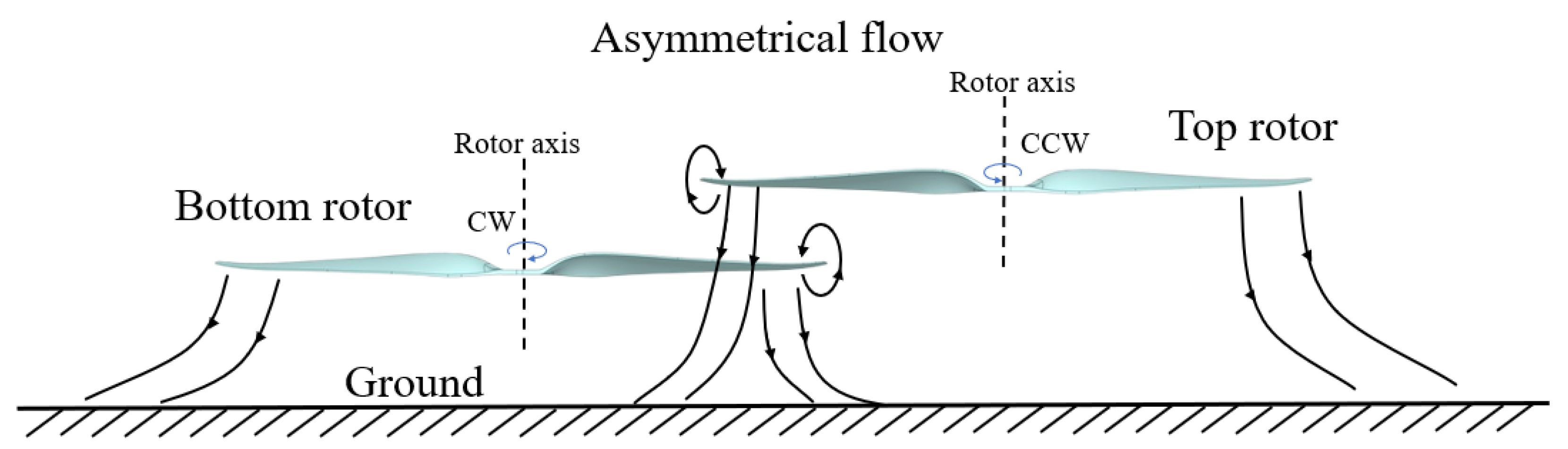
Figure 1 describes the significant flow patterns in the staggered rotor system, which operates IGE. In the top view, the top rotor rotates counterclockwise (ccw) around the rotor axis, while the rotation direction of the bottom rotor is clockwise (cw). Owing to the spatial asymmetry of the system, the complex flow near the ground lacks symmetry, resulting in distinct performance characteristics of the staggered rotor IGE.
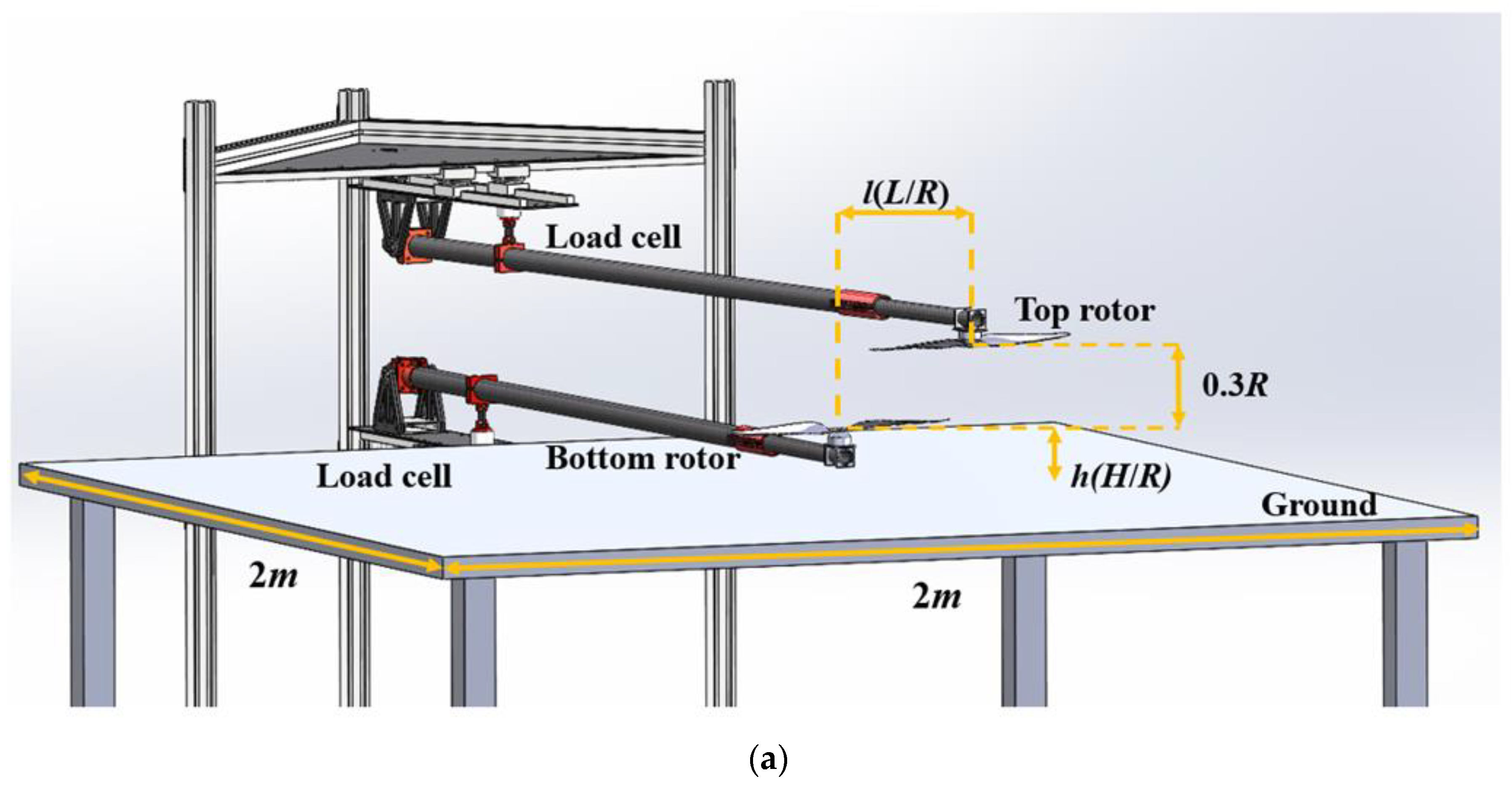
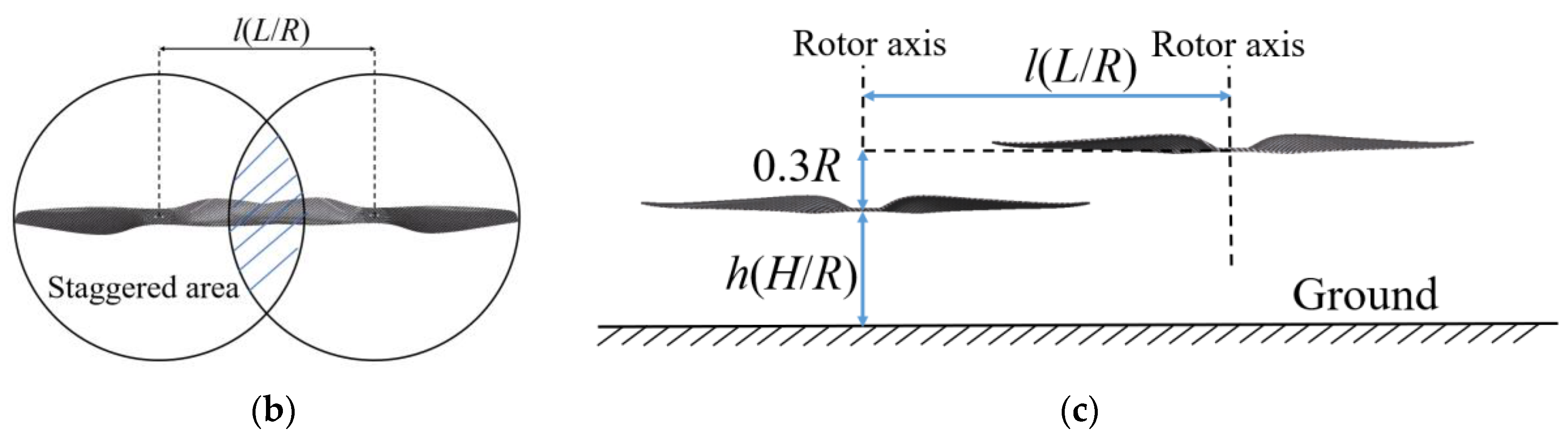
The experiment used a T-MOTOR 1855 propeller integrated with carbon fiber. A single propeller consists of two blades, each having a radius of 9 inches (228.6 mm) and a pitch of 5.5 inches (139.7 mm). To normalize the connection between distance and rotor radius, h is defined as h = H/R, where H is the distance from the center of the bottom rotor to the ground and R is the rotor radius. From the actual design and safety considerations of the staggered rotorcraft, the vertical distance of rotors is fixed at 0.3R; l is defined as l = L/R, and the meaning of L is the lateral distance between the rotors. Figure 2 illustrates the experimental instruments and definitions used in the experiment.
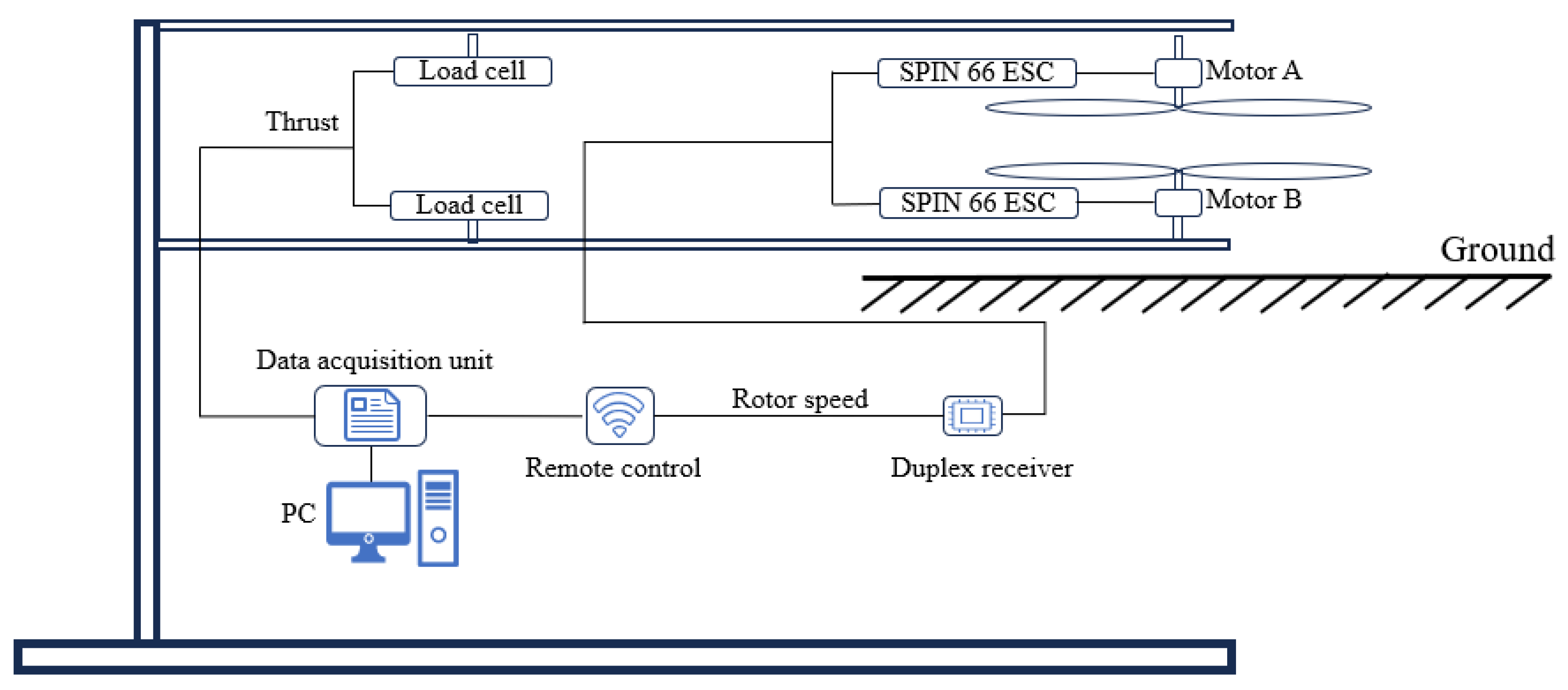
Prior to the experiment's start, specialized equipment is used to detect the vibration of the experimental equipment. The second-order natural frequency of the testbed is between 93 and 154 Hz, while the highest frequency of the rotor under all test conditions is 58.3 Hz. According to the experimental results, the natural frequency of the experimental device does not have an impact under these experimental conditions. As shown in Figure 3, when receiving the throttle signal from the remote control, the electronic speed controller (ESC) controls the motor rotation. Real time rotation angular velocity can be displayed on the remote control. Meanwhile, the thrust can be measured by the load cell. The main equipment for the experiment is shown in Table 1.
2.2. Operating Conditions
The unloaded rotor speed was referenced from previous staggered rotor UAVs [35,36], but considering the decrease in rotor speed during the landing process, speeds commonly ranging from 1000 to 3500 were selected. Under these conditions, the Reynolds number at the blade tip is between 0.26 × 10⁵–1.15 × 10⁵, the blade tip velocity is between 24 and 84 m/s, the blade tip Mach number is between 0.05 and 0.25, and the lateral distances are 0, 0.5, 1.0, 1.5, and 2.0, respectively. In the current study, ground height conditions are considered at h = 0.5, 1.0, 1.5, and 2.0, with the bottom rotor height (h) extending up to 3.5 above the ground. According to the theory proposed by Leishman [37] and experimental results from Lokesh Silwal [30], it is believed that being 3R above the ground can be considered an OGE condition. Tan J.F.’s research [33] indicates that the primary influence of the ground on tandem rotors occurs near the rotors. At the extreme positions in the experiment, the distances from the center of rotor rotation to the edge of the table are 3.38 R and 4.38 R, respectively. Therefore, this experimental condition is considered appropriate. Table 2 illustrates the operational conditions of the experiment.
2.3. Performance Metrics
An important parameter for assessing rotorcraft is the thrust in hover. The thrust formula for a single-rotor OGE is as follows:
- -
- T represents the thrust,
- -
- ρ represents the density of the air,
- -
- A represents the rotor disk area,
- -
- Ω represents the rotation speed,
- -
- R represents the rotor radius.
- -
- CT can be derived from Equation (1) and expressed as:
The ratio of rotor thrust IGE Tige to rotor thrust OGE Toge, denoted Tige/Toge, represents the intensity of the ground effect. This ratio compares the thrust under IGE conditions to the thrust under OGE conditions. It provides insight into how the ground affects the rotor’s performance and helps assess the significance of the ground effect in different operational scenarios.
3. Error Analysis and Validation
To demonstrate the credibility and measurement accuracy of the experimental results, new experimental verifications were conducted. Tests were performed using 1 kg and 4 kg mass standard blocks, and after multiple measurements, the results were recorded as 1.003 kg and 4.004 kg, respectively. The maximum measurement deviation was found to be 0.3%, indicating that the measurement accuracy of the sensor aligns with the requirements of the experiment. The measurement error of angular velocity is attributed to the motor’s structure. Depending on the chosen motor, the systematic error is 4.26 RPM.
The thrust coefficient (y) is calculated based on the rotational speed (x1) and thrust (x2). According to the calculation method of uncertainty [38], the determination of uncertainty is as follows:
Substitute the thrust coefficient:
According to calculations, the maximum measurement error of CT is 1.4%
4. Results and Analysis
Firstly, the thrust of the isolated rotor OGE and IGE was exhibited. Secondly, the influences of rotor speed, distance above the ground, and lateral distance on the thrust IGE were assessed, along with their impact on Tige/Toge. In the analysis, the isolated rotor system was also introduced as a contrast to evaluate the performance of the staggered rotors.
4.1. Isolated Rotor Performance
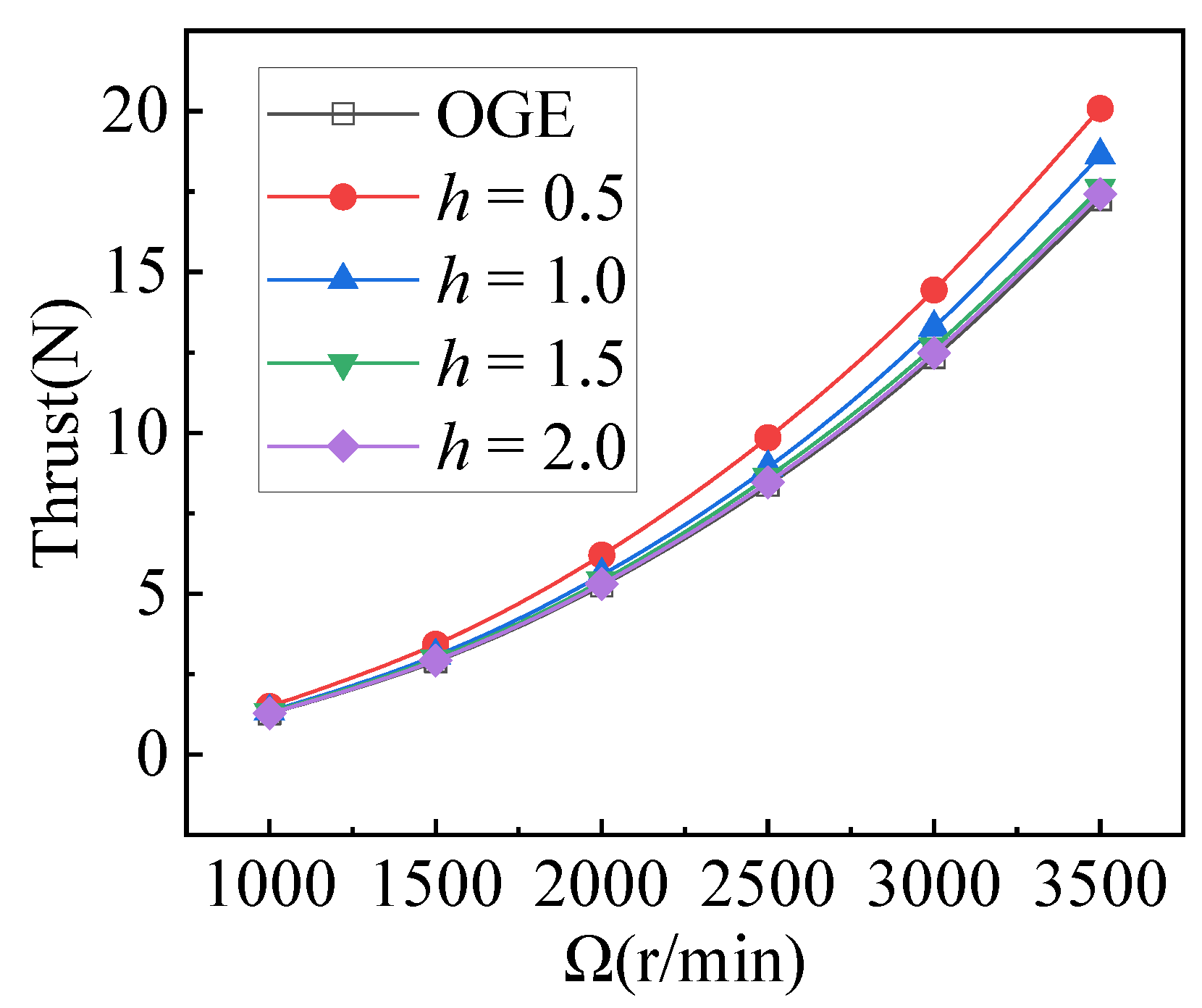
For comparative experiments on the staggered rotor system under conditions without interference between rotors, it’s essential to first conduct thrust experiments on an isolated small-scaled rotor rotating at various speeds and heights above the ground. This process involves comparing the experimental results with the model derived from theoretical deductions [10] to establish a baseline understanding of the isolated rotor’s performance characteristics.
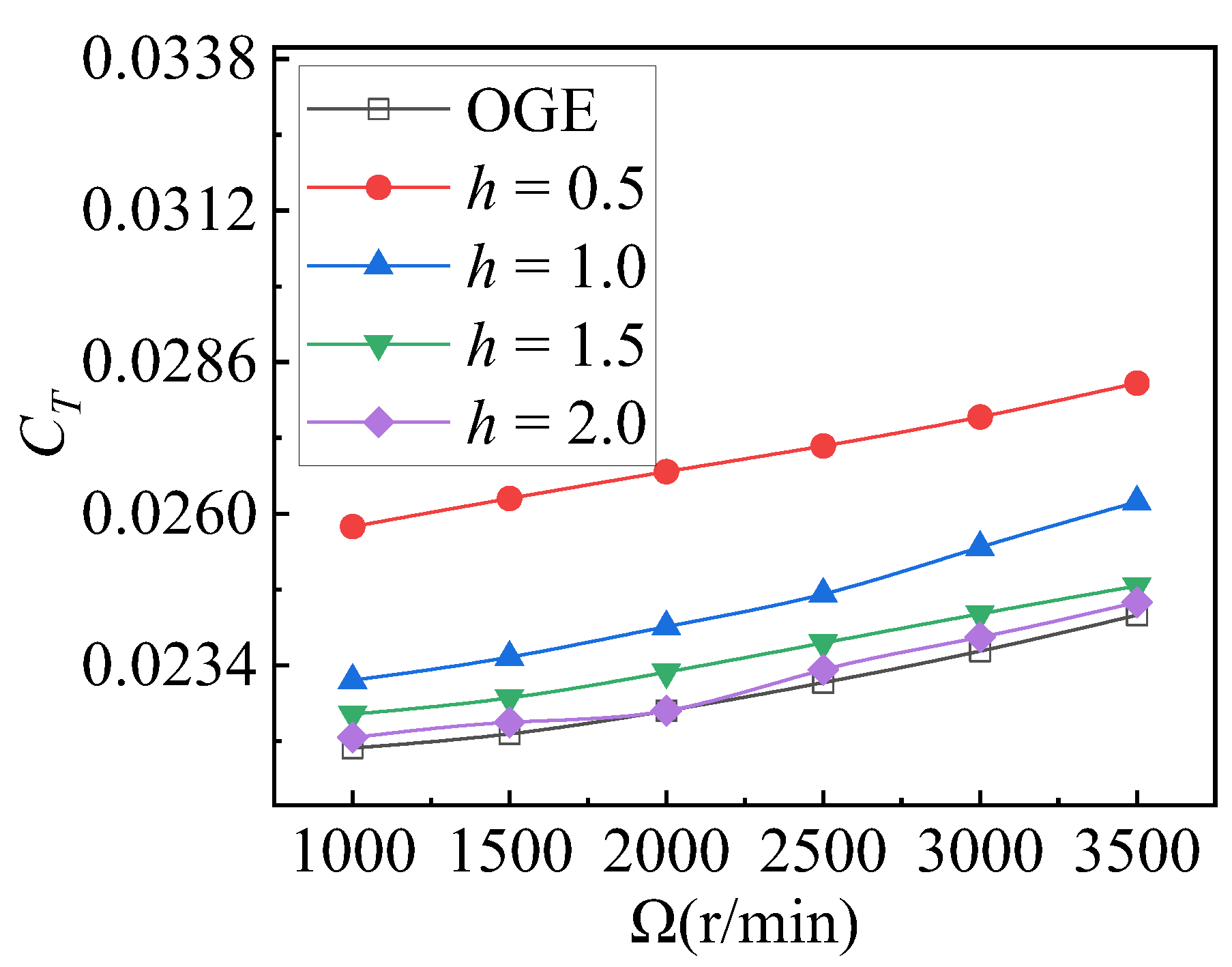
The isolated rotor experiment was conducted in the absence of another rotor and its supporting structure. Figure 4 illustrates the relationship between rotor thrust and rotational speed at different heights. The thrust, at various distances from the ground, changes with rotor speed and approximates a quadratic function. Notably, the thrust increases as the altitude decreases. In Figure 5, the trend of CT calculated by the formula varies with rotor speed. CT increases with an increase in rotor speed and decreases with altitude. This observation aligns with the expected behavior of rotor systems IGE conditions.
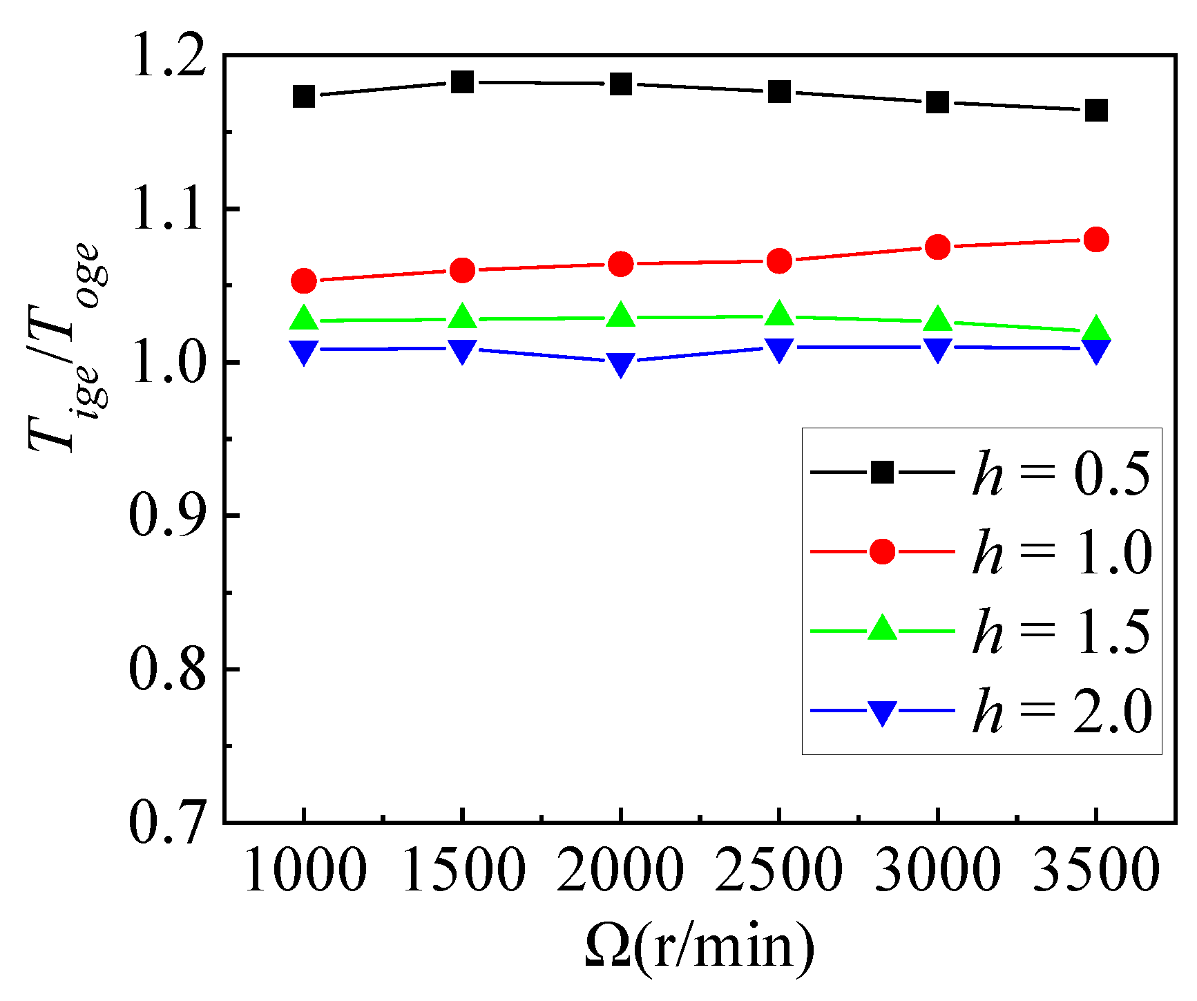
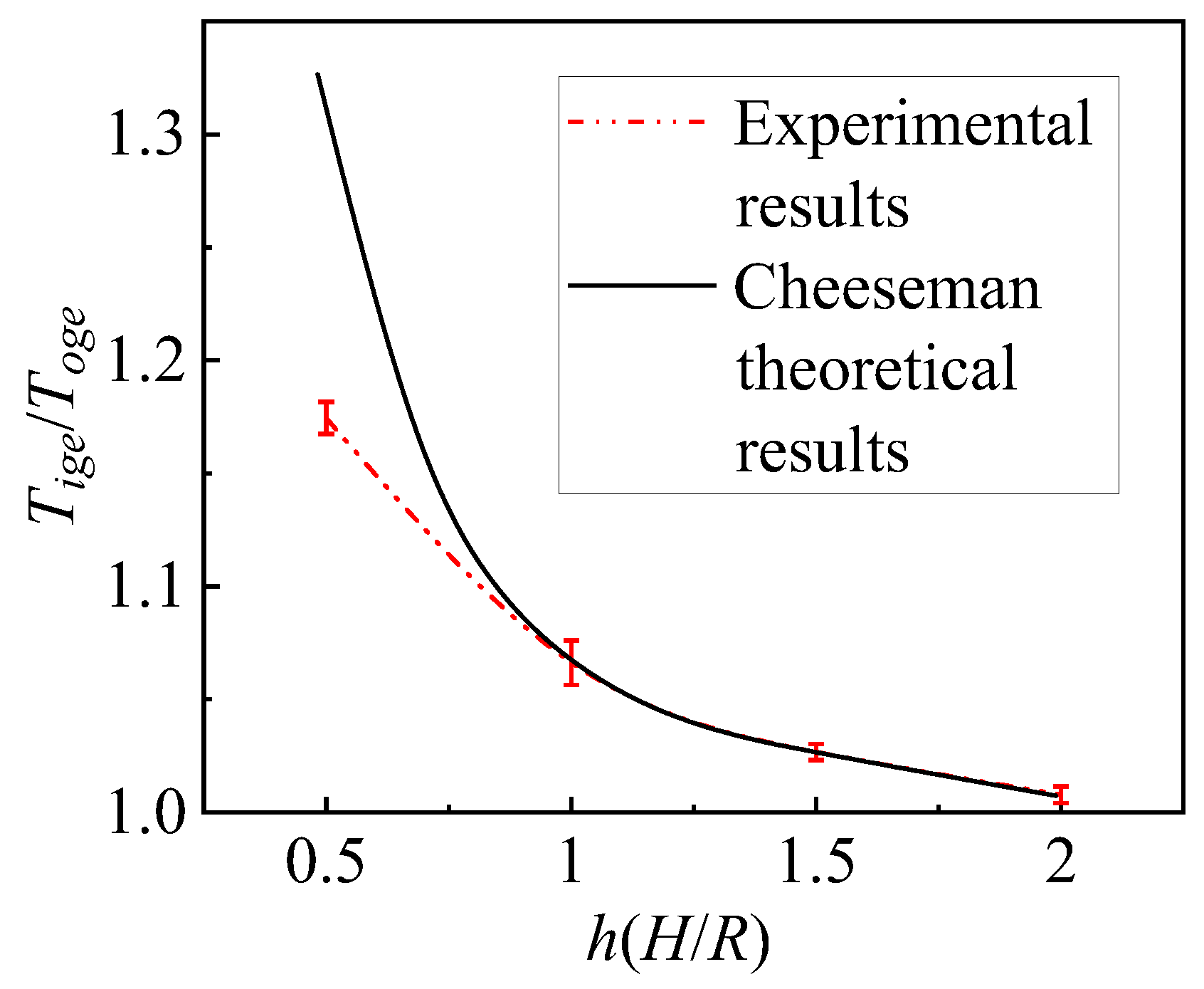
Measuring the strength of the ground effect is another critical parameter, represented by Tige/Toge. According to Cheeseman and Bennett’s theoretical model [10], . It’s significant to observe that this model does not account for rotor speed as a factor. In Figure 6, it is observed that changes in rotor speed have minimal impact on the thrust ratio for the isolated rotor. In Figure 7, the curve’s error bars represent the deviation measured at different speeds. The theoretical predicted model and actual experimental results coincide when 1.0 ≤ h ≤ 2.0. However, at h = 0.5, experimental values deviate significantly from theoretical predictions. This discrepancy is attributed to a singularity in the model occurring at h = 0.25 and at h = 0.5, being close to the singularity position, causing prediction failure. Considering the disappearance of the ground effect for the isolated rotor, it is generally assumed that the ground effect disappears at h = 2.0, which is consistent with the behavior of a single-rotor helicopter.
4.2. Staggered Rotor System Performance
For a rotorcraft in the hovering state, the thrust of the rotor is a direct and significant performance indicator. The newly configured staggered rotorcraft has shown a significant improvement in thrust performance within limited spatial dimensions [29]. However, similar to the periodic thrust fluctuations observed in coaxial dual-rotor systems during operational states [39], a comparable scenario is evident in staggered rotors. When two rotors intersect, the variation in rotor chord thickness during the intersection process influences thrust changes. Additionally, airflow near the rotor induced by rotor attachment vortices causes variations in certain regions, affecting rotor thrust. However, during rotor interaction with ground effects, upwash and downwash of airflow are amplified or weakened in different regions, leading to more complex flow patterns. Periodic fluctuations in rotor thrust become unpredictable, significantly affecting measurement precision. Due to limitations in sensor sampling frequencies, accurately capturing these thrust variations is challenging. Therefore, in situations where thrust exhibits periodic changes, selecting the median thrust proves to be a reliable and practical approach to assess thrust performance.
4.2.1. Effects of Rotor Speed
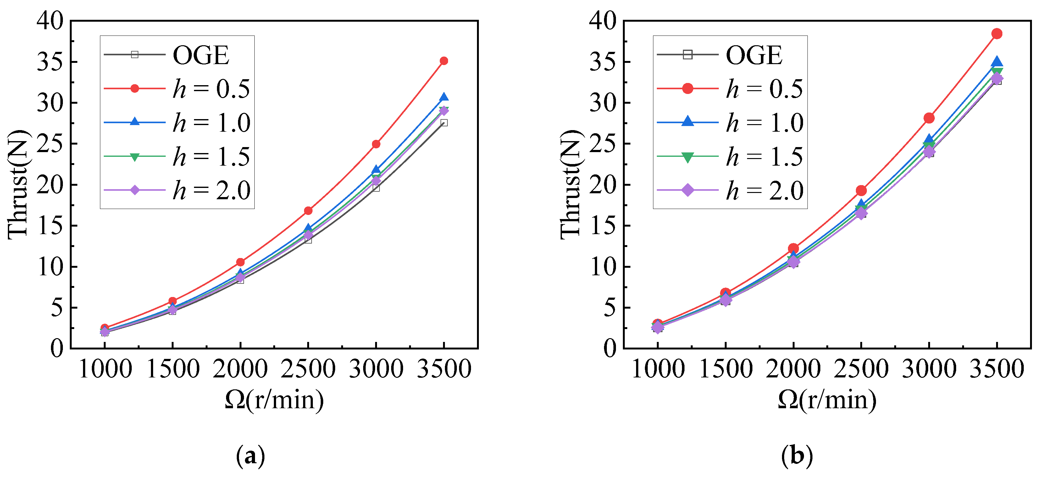
The rotor speed affects two aspects of the multi-rotor performance IGE. Firstly, it affects aerodynamic thrust, and secondly, it affects the thrust ratio. In Figure 8, the thrust of the rotor continues to exhibit an approximately quadratic relationship with rotor speed, resembling the behavior observed in previous isolated rotor studies. As rotor speed increases and the altitude decreases, the augmentation effect of ground on rotor aerodynamics becomes more pronounced. Similar trends are observed in experiments with other lateral distances, indicating the consistent influence of rotor speed and ground proximity on aerodynamic performance across varying configurations.
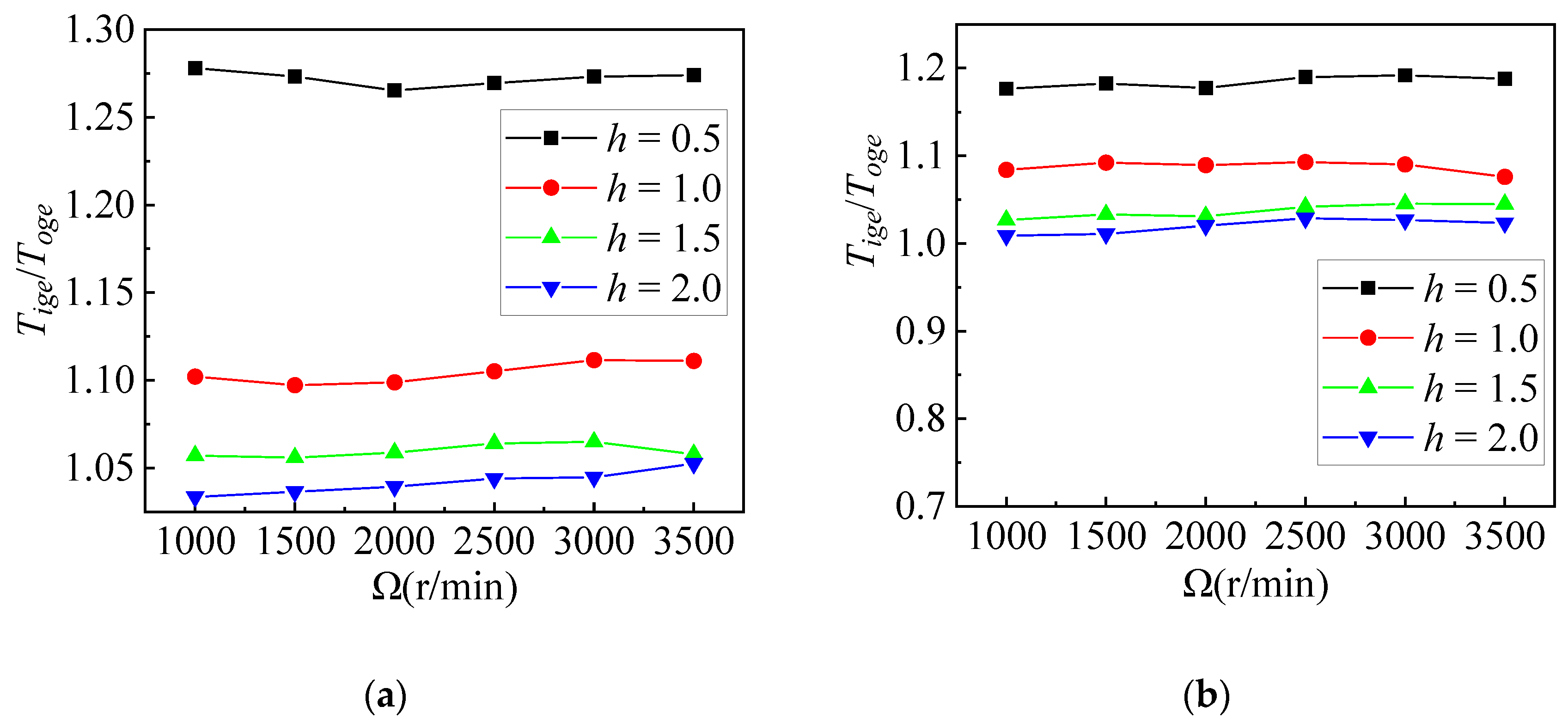
In isolated rotors, the rotational speed typically does not significantly affect the ratio of tensile forces, but this has not been conclusively proven in staggered rotor systems with aerodynamic interference. Figure 9 depicts the ratio of IGE to OGE for lateral distances of 0.5 and 1.5. It is apparent that the ratios measured for the staggered rotor system under different speed conditions are nearly equal. The minor fluctuations in the curves fall within the acceptable range of experimental error. Similar trends are observed for other lateral distances as well. Therefore, the impact of rotor speed on the thrust ratio in the staggered rotor system can be neglected. In the ground effect of planar multi-rotors, experimental results from Otsuka [25] and Conyers [16] indicate that rotor speed has a minor impact on Tige/Toge. This observation is further supported by the rotor ground effect aerodynamic prediction models proposed by He [3], and Sanchez-Cuevas [19]. Consequently, in subsequent studies, the comparison of thrust ratios at different speeds will no longer be conducted. Instead, the thrust ratios measured at different speeds will be averaged for analysis.
4.2.2. Effects of Ground Distance
The varying distances above the ground lead to different effects of the ground on rotor aerodynamics. In general, closer proximity to the ground results in a more pronounced ground effect. However, due to the fountain effect of multi-rotors, which promotes the development of turbulent regions, researchers such as Otsuka, Conyers, Stephen and Healy et al. [16,23,25] has discovered some contradictory conclusions. Regarding various configurations of staggered rotors, the influence of ground clearance on rotor systems requires thorough investigation. Different factors, such as rotor spacing, rotor geometry, and ground conditions, can influence the aerodynamic interactions between the rotors and the ground, leading to varied effects on performance. Therefore, comprehensive studies are vital to understanding how the parameters influence the aerodynamics of staggered rotor systems IGE.
Given the spatial arrangement of rotors, we introduce another set of comparative variables. The experimental outcomes encompass measurements of isolated top rotors and isolated bottom rotors, both IGE and OGE. The top rotor is sampled starting from a distance of 0.8R from the ground, while the bottom rotor is sampled starting from a distance of 0.5R from the ground. The total aerodynamic thrust outcomes are employed to compare the isolated system of two rotors with the staggered rotor system. The sampling approach is determined by the distance in the staggered rotor system. The sampling conditions for the top rotor are consistent with those for the staggered rotor system, and the same applies to the bottom rotor. Adding two isolated rotor systems as a comparison can eliminate the influence of aerodynamic interference between rotors, making it easier to compare the performance of rotor systems at different ground heights. Previous studies on unloaded flight experiments [35] indicate that the operating condition for this rotor model is approximately 1500 RPM. Considering the loaded flight of the aircraft, 2000 RPM is chosen as a typical operating condition for the subsequent study on thrust variation.
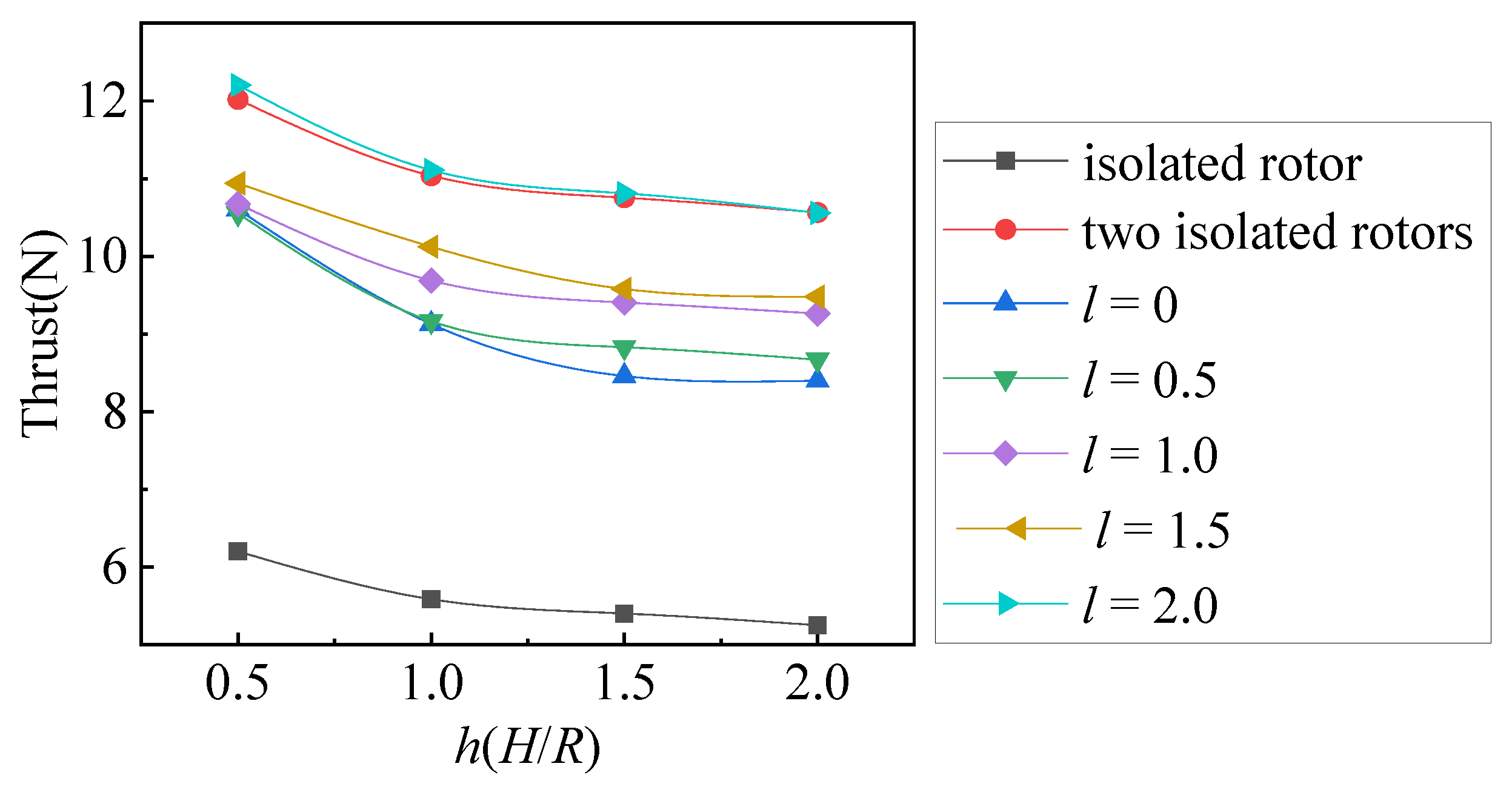
Figure 10 illustrates that whether it is a two-isolated rotor system or a staggered rotor system, the closer they are to the ground, the more significant the improvement in thrust performance. At the same distance above the ground, compared with the two isolated rotor systems, the staggered rotor system still experiences thrust loss. This loss can be attributed to the alteration in the angle of attack of the bottom rotor due to its immersion in the downwash flow generated by the top rotor [40]. In conditions closer to the ground (h = 0.5), the ground evidently improves the performance of the staggered rotors, thereby alleviating the thrust loss caused by the interference of the bottom rotor. However, under conditions far from the ground (h = 2.0), this interference becomes more pronounced. In situations of low altitude, the ground constrains the free flow of the rotor wake, resulting in reduced inflow, increased rotor blade angle of attack, and hence increased thrust. Conversely, under conditions of high altitude, due to the effect of air viscosity, rotor tip vortices gradually decay and spread, weakening the ground’s restriction on wake flow and causing the wake to more closely resemble free flow, thereby resulting in decreased thrust of the rotor system.
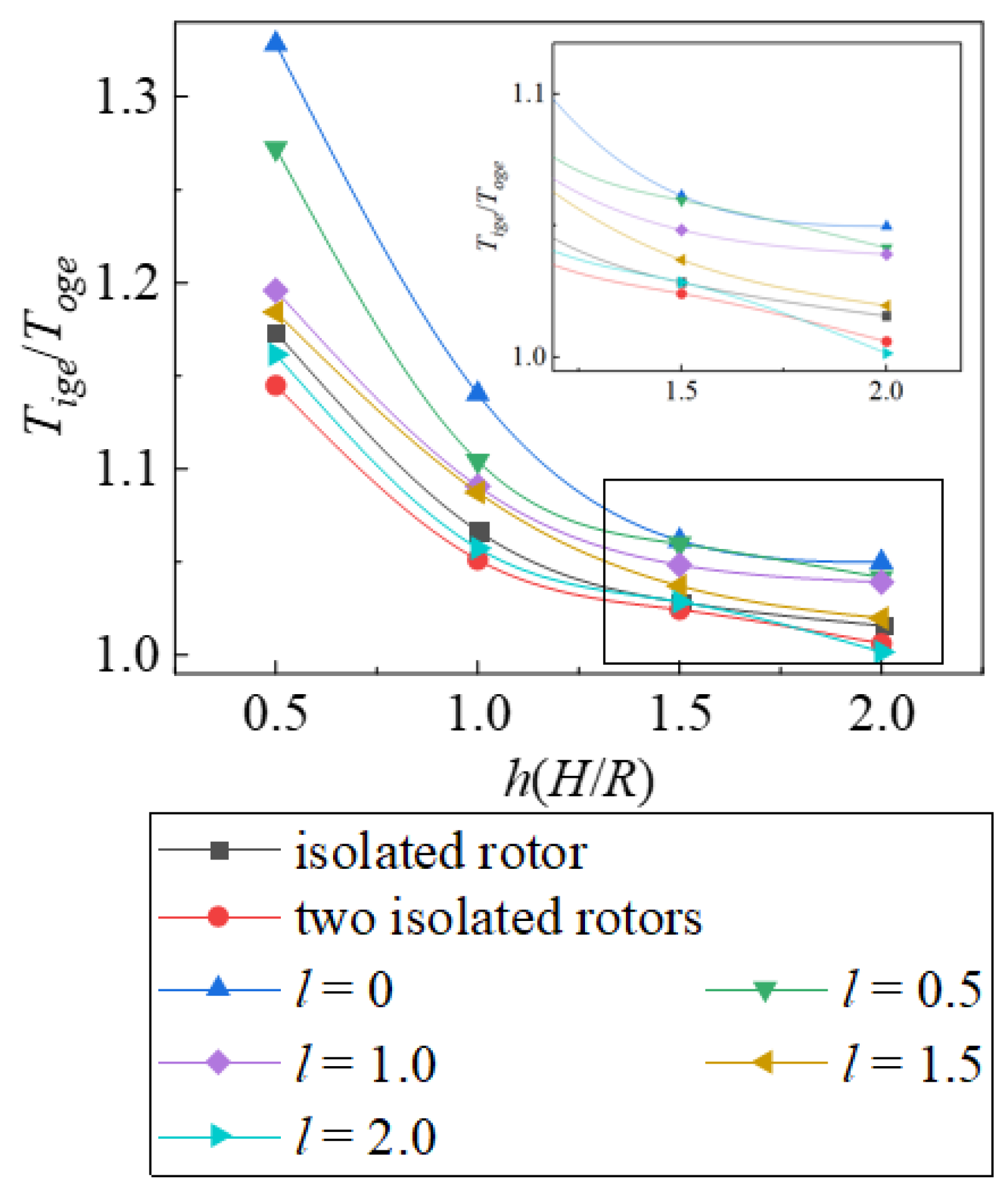
Figure 11 illustrates the decrease in the ratio of thrust with increasing distance from the ground for each rotor system. Both the staggered rotor system and the two-piece isolated rotor system show a decrease in the ratio of thrust with increasing altitude above ground, without encountering anomalies in the ratio as observed in planar multi-rotor systems. Otsuka and Healy [23,25] suggest that induced effects of rotor tip vortices causing fountain flow near the blade tip are factors contributing to thrust loss, yet in the staggered rotor system, where the two rotors overlap spatially, such induced fountain flow near the rotor tip is absent. Considering the point where the ground effect is typically assumed to vanish for helicopters, h = 2.0, some differences emerge in the performance of staggered rotors. In the staggered rotor system, significant ground effect is still observable in regions where rotor overlap is substantial l ≤ 1.0, with the ratio near 1.05. This phenomenon occurs due to the limited influence of ground effect on the wake of isolated rotors under conditions relatively distant from the ground. Conversely, in the staggered rotor system, compared with the isolated rotor, the overlapping of rotors leads to a higher downwash intensity [32]. Consequently, when the rotor tip vortices reach the ground, they maintain a relatively high intensity, and the ground’s restriction on the wake remains noticeable, reducing rotor inflow and thus resulting in the continued presence of the ground effect.
4.2.3. Effects of Lateral Distance
The lateral distance characterizes the size of overlap region, affecting the downwash, the inflow, the outwash and upwash flow near the ground surface.
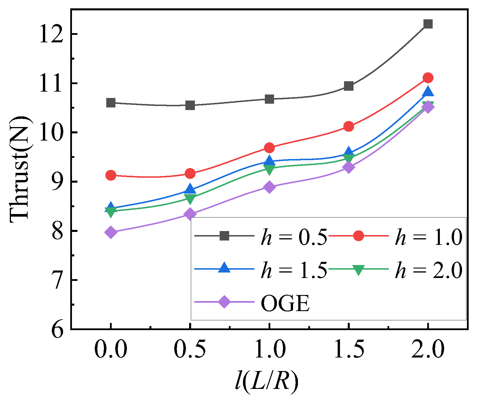
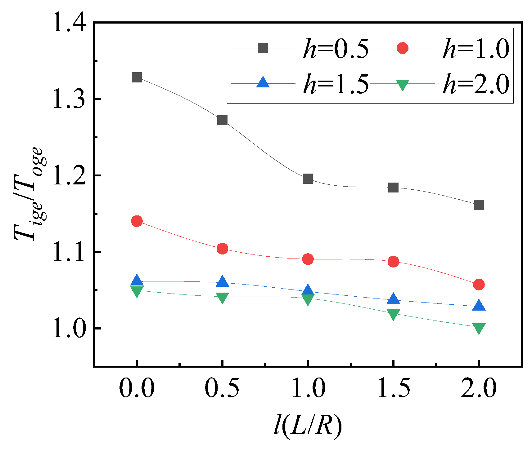
Figure 12 illustrates that with the increase in lateral distance, the thrust at different distances above the ground increases. However, as shown in Figure 13, with the elevation in the lateral distance, Tige/Toge decreases. The opposite trends between changes in thrust values and changes in thrust ratios are associated with aerodynamic interference in the staggered rotor system. Similar to staggered rotor systems without ground effect, as the lateral distance expands, the bottom rotor gradually moves away from the interference of the top rotor’s downwash, and the top rotor also moves away from the interference zone of the bottom rotor’s rotor tip vortices, leading to improved thrust performance. When the lateral distance is small, the contraction of the top rotor downwash passes through the bottom rotor disc, causing a portion of the wake to be included within the downwash of the bottom rotor. The flow pattern formed near the ground is closer to that of an isolated rotor, but near the rotor’s axis of rotation, the ground may exhibit more pronounced stagnation effects. As the lateral distance expands, the overlap region of the rotors reduces, and the intensity of the downwash diminishes. Consequently, the stagnation effect weakens, leading to a reduction in the improvement of thrust performance, resulting in a decrease in the thrust ratio.
5. Discussion
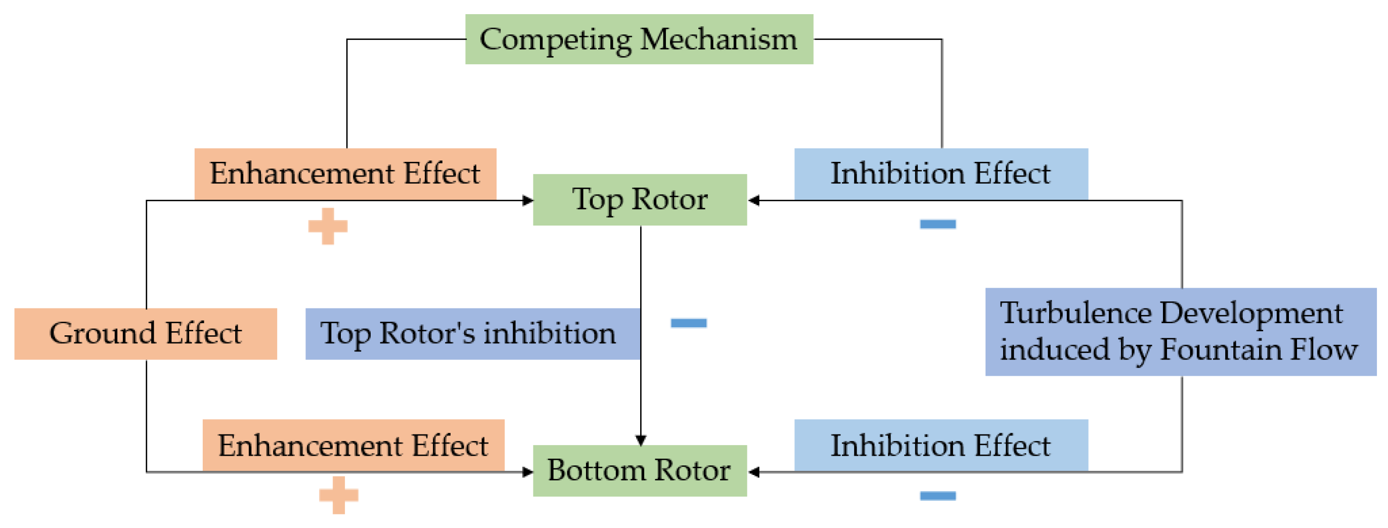
The fountain effect generally refers to the phenomenon where multiple airflows from the rotor ground effect collide with the ground, forming a stagnation region where the airflow has nowhere to go but ultimately rises. A large amount of turbulence is generated by the downwash airflow hitting the ground and changing direction. Simulations and experiments conducted by several scholars [20,22,23,32,33] using different propeller blades, airfoil shapes, and pitches have consistently demonstrated the existence of fountain flow. The fountain flow brings a significant amount of turbulence, further promoting turbulence development and causing it to rise to the rotor plane, resulting in reduced thrust for the rotor. According to the research by He [20] and our experiments, changes in rotor speed have almost no effect on the thrust loss caused by the fountain flow. The staggered rotor system exhibits both inhibitory and enhancing effects, consistent with the conclusion of Silwal [30] et al. The loss caused by the fountain flow represents an inhibitory effect, and similarly, the top rotor has an inhibitory effect on the bottom rotor, while the ground effect manifests as an enhancing effect, as shown in Figure 14. The specific competitive mechanism depends on the relative strengths of the enhancing and inhibitory effects and warrants further discussion.
5.1. Combination of Rotor to Rotor Interactions and Ground Effect
As the staggered rotor system approaches the ground, it encounters complex flow dynamics characterized by rotor-vortex-ground coupling interference. In this scenario, the mutual interference between rotors induces certain thrust losses while the rotor experiences an increase in thrust IGE. The combined influence of these two effects results in intricate variations in the thrust of the staggered rotor system. This interplay between aerodynamic interference and ground effect underscores the complexity of rotorcraft dynamics, particularly in low-altitude flight scenarios. Further analysis and experimentation are crucial to fully understand and optimize the performance of staggered rotor systems in such conditions.
5.1.1. Impact on Thrust IGE
From Figure 10, it is evident that the sum of thrusts from two isolated rotor systems is significantly greater than that of most staggered configurations, indicating that the complex interference between rotors affects the performance of staggered rotor systems. However, this does not necessarily imply that this influence on rotor thrust performance is unfavorable. Under the condition where l = 2.0, the staggered rotor thrust is even slightly greater than that of the two isolated rotors. This could be ascribed to the reduction in the overlap area, causing the top rotor’s downwash to contract almost completely, avoiding the inflow region of the bottom rotor. Thus, the interference experienced by the bottom rotor is minimal, while the shedding of the bottom rotor tip vortices induces upwash on the tip region of the top rotor, causing a marginal increase in system thrust. In Figure 12, within the two regions where (h = 0.5) and (l ≤ 1.0), and (h = 1.0) and (l ≤ 0.5), the thrust performance of the rotors remains nearly unchanged with increasing lateral distance. This is because, in these scenarios, where the rotor is at a low altitude, the improvement in thrust performance due to ground effect predominates. The ground effects on the aerodynamics of the staggered rotor system far outweigh the effect of aerodynamic interference within the system. This is attributed to the low altitude, where the ground effect predominantly enhances the thrust. The aerodynamic influence of the ground on the staggered rotor system surpasses the impact of aerodynamic interference within the system. However, as the altitude increases, the ground effect weakens, and a balance point is reached where the influence of the ground and aerodynamic interference within the system are of similar magnitude. With further increases in distance above the ground, where the intensity of the ground effect is lower than the balance point, the effects of aerodynamic interference between rotors become more significant. Increasing the lateral distance results in a noticeable improvement in rotor thrust performance under these conditions.
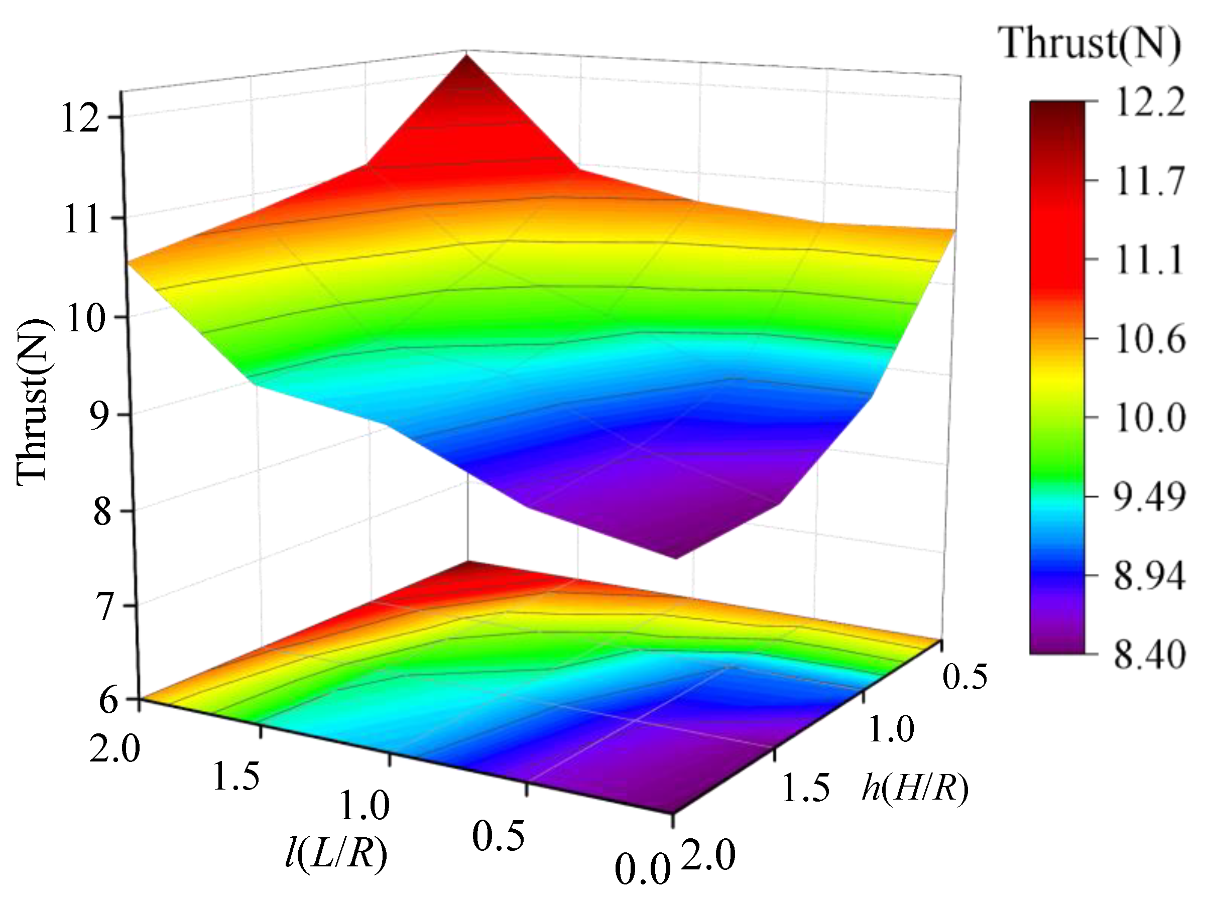
In Figure 15, in different experimental ranges, these two types of interference exhibit significant differences in their effects on thrust, ultimately manifesting as optimal thrust performance at (l = 2.0) and (h = 0.5) and poorest performance at (l = 0) and (h = 2.0). With the increase in lateral distance and the decrease in distance above the ground, thrust performance improves significantly. However, the difference lies in that the increase in lateral distance brings about a nearly uniform enhancement in performance, whereas the influence of distance from the ground shows a more pronounced increase within the range of 0.5 ≤ h ≤ 1.0.
5.1.2. Impact on Thrust Ratio IGE
Figure 16 illustrates how the thrust ratio varies with lateral distance and distance above the ground, corresponding to variations in thrust. Unlike thrust performance, however, the ratio value reflects the gain of the rotor ground effect in different configurations. With an increase in lateral distance, the ratio tends to decrease, with this trend being more pronounced under conditions closer to the ground. Among all rotor configurations tested, the ground effect is most significant for (l = 0), with a thrust increment of up to 32.8%. The region where the ground effect significantly improves rotor performance remains predominantly under conditions of closer proximity to the ground and smaller lateral distance, consistent with the previous analysis.
5.2. Effect on the Top and Bottom Rotors at h = 2.0
In the previous analysis, it was observed that some rotor configurations still exhibit significant ground effects at (h = 2.0). Subsequent analysis will investigate the impact on the top and bottom rotors separately.
Figure 17 illustrates the variation of the ratio for the top rotor, bottom rotor, and staggered rotor system at h = 2.0 and h = 0.5. The thrust is compared to that of the staggered rotor system separately in OGE conditions. It is noteworthy that almost all bottom rotors exhibit thrust performance without ground effect and even experience slight thrust losses at h = 2.0. For isolated rotors, the closer they are to the ground, the more significant the ground effect becomes, while in the staggered rotor system, the opposite phenomenon occurs. At h = 2.0, the top rotor contributes nearly all of the thrust enhancement, which is entirely contrary to the scenario at h = 0.5, where the bottom rotor predominantly contributes to the enhancement. The top rotor continues to demonstrate significant thrust augmentation within the range of 0 ≤ l ≤ 1.5, with the maximum thrust increment reaching 109.5%. This implies that at h = 2.0, the performance of the staggered rotor system IGE, the top rotor primarily contributes to thrust enhancement, while the bottom one, due to being affected by the fountain flow effects, downwash of the top rotor, and ground influence, exhibits a pseudo-OGE state.
The disparity in thrust performance between the rotors in the staggered rotor system at h = 2.0 can likely be attributed to the combined effects of fountain flow and turbulent development. The non-coplanar arrangement of the two rotors in the staggered rotor system induces asymmetrical fountain flow, which may contribute to the differences in thrust performance. Previous studies [22,23,25] have indicated that fountain flow rises to the rotor plane, generating substantial turbulence that can lead to rotor thrust loss. In staggered rotor configurations with partially overlapping regions, the fountain flow may rise even higher, and the presence of a multi-stream downwash could lead to multiple fountain flows. The mixing of these multiple fountain flows may further enhance turbulence development, as observed in studies such as Tan’s research [33] on the ground effect of tandem rotor systems. Due to the vertical separation between the top and bottom rotors, the turbulence induced by fountain flow likely predominantly affects the bottom rotor, while the top largely avoids the turbulent interference zone. As the lateral distance expands, the upward extent of the fountain flow decreases. However, the bottom rotor also avoids interference from the top rotor, and their effects are of comparable magnitude. Consequently, the bottom rotor exhibits a pseudo-OGE state with a thrust ratio of 1. The increased lateral distance reduces the strength of the downwash in the staggered rotor system, weakening the impact of downwash IGE while enhancing the inflow to the top rotor, resulting in reduced thrust.
6. Conclusions and Future Work
The study primarily concentrates on evaluating the performance of staggered rotors under the influence of ground effects. Under these conditions, the following conclusions have been drawn:
- (1)
- In the ground effect, increasing rotor speed improves the thrust performance of both isolated rotor and staggered rotors, but the rotor speed barely affects the ratio of thrust IGE or OGE.
- (2)
- As the distance above the ground increases, both isolated rotors and staggered rotors experience a decrease in thrust performance and thrust ratio. The position where the ground effect disappears for staggered rotor systems is farther away (hoge > 2.0) compared to the position where the ground effect disappears for isolated rotor systems.
- (3)
- As the lateral distance expands, the staggered rotor thrust improves, but the ratio of thrust decreases.
- (4)
- The weakening effect of mutual interaction between staggered rotors and the strengthening effect of ground effect both coexist. The impacts of these two effects distribute differently: while the increase in lateral spacing leads to a uniform reduction in the interaction between rotors, affecting both thrust performance and thrust ratio almost evenly, the enhancement of ground effect due to decreasing distance from the ground experiences a sharp increase within the 0.5 ≤ h(H/R) ≤ 1.0 interval.
- (5)
- At h(H/R) = 2.0, certain configurations of staggered rotor systems are still influenced by ground effect. In this scenario, the thrust variation of bottom rotor behaves similarly with OGE state while the top rotor thrust experience an increase.
The thrust of the staggered rotors was measured using a validated experimental setup and contrasted with that of the isolated rotor under the same conditions. The investigation examined the underlying mechanisms driving variations in thrust, which result from interactions among rotors and between rotors and the ground. Understanding these interactions can offer valuable insights for optimizing the design of multi-rotor drones.
Our work will consider the ground effects of staggered rotors and introduce variables such as rotor radius, angle of attack, power, etc. By considering key parameters like rotor radius, lateral spacing, and height above ground as variables, through training a regression analysis model, we will develop a surrogate model capable of accurately predicting the ground effect aerodynamic forces of staggered rotors. Subsequently, we plan a rational flight path for the autonomous landing of the aircraft. Perform flow field visualization studies on ground effect experiments of staggered rotors with specific parameters, aiming to fully elucidate the flow phenomena observed and reveal flow patterns.
Author Contributions
Conceptualization, H.Z. and H.N.; Methodology, H.Z.; Validation, S.W.; Formal analysis, Y.D.; Investigation, H.Z. and S.W.; Resources, X.W.; Writing—original draft, H.Z. and S.W.; Writing—review & editing, H.Z. and Y.D.; Visualization, Y.D.; Supervision, H.N. and X.W.; Project administration, H.N. and X.W.; Funding acquisition, H.Z. and H.N. All authors have read and agreed to the published version of the manuscript.
Funding
This research was funded by the National Natural Science Foundation of China (He Zhu, No. 52202443; Hong Nie, No. 52275114), China Postdoctoral Science Foundation (He Zhu, 2023M731656), National Key Laboratory of Helicopter Aeromechanics Foundation (He Zhu, 2023-HA-LB-067-05e), Natural Science Foundation of Jiangsu Province (He Zhu, No. BK20220898), Jiangsu Funding Program for Excellent Postdoctoral Talent (He Zhu, No. JB0202003), Aeronautical science foundation of China (He Zhu, No. 20232010052002).
Data Availability Statement
The data presented in this study are available on request from the first author.
Conflicts of Interest
The authors declare no conflicts of interest.
References
- Doo, J.; Pavel, M.; Didey, A.; Hange, C.; Diller, N.; Tsairides, M.; Smith, M.; Bennet, E.; Bromfield, M.; Mooberry, J. NASA Electric Vertical Takeoff and Landing (eVTOL) Aircraft Technology for Public Services—A White Paper; NASA: Washington, DC, USA, 2021.
- Thipphavong, D.P.; Apaza, R.; Barmore, B.; Battiste, V.; Burian, B.; Dao, Q.; Verma, S.A. Urban Air Mobility Airspace Integration Concepts and Considerations. In Proceedings of the 2018 Aviation Technology, Integration, and Operations Conference, Atlanta, GA, USA, 25–29 June 2018. [Google Scholar]
- Ugwueze, O.; Statheros, T.; Bromfield, M.A.; Horri, N. Trends in eVTOL Aircraft Development: The Concepts, Enablers and Challenges. In Proceedings of the AIAA SCITECH 2023 Forum, National Harbor, MD, USA, 23–27 January 2023. [Google Scholar]
- Ugwueze, O.; Statheros, T.; Horri, N.; Bromfield, M.A.; Simo, J. An Efficient and Robust Sizing Method for eVTOL Aircraft Configurations in Conceptual Design. Aerospace 2023, 10, 311. [Google Scholar] [CrossRef]
- Zhang, H.; Zou, Y.; Zhang, Q.; Liu, H. Future urban air mobility management: Review. Acta Aeronaut. Et Astronaut. Sin. 2021, 42, 24638. [Google Scholar] [CrossRef]
- Li, Y.; Liu, M. Path Planning of Electric VTOL UAV Considering Minimum Energy Consumption in Urban Areas. Sustainability 2022, 14, 13421. [Google Scholar] [CrossRef]
- Qu, W.; Xu, C.; Tan, X.; Tang, A.; He, H.; Liao, X. Preliminary Concept of Urban Air Mobility Traffic Rules. Drones 2023, 7, 54. [Google Scholar] [CrossRef]
- Matus-Vargas, A.; Rodriguez-Gomez, G.; Martinez-Carranza, J. Ground effect on rotorcraft unmanned aerial vehicles: A review. Intell. Serv. Robot. 2021, 14, 99–118. [Google Scholar] [CrossRef]
- Darvishpoor, S.; Roshanian, J.; Raissi, A.; Hassanalian, M. Configurations, flight mechanisms, and applications of unmanned aerial systems: A review. Prog. Aerosp. Sci. 2020, 121, 100694. [Google Scholar] [CrossRef]
- Cheeseman, I.; Bennett, W. The Effect of the Ground on a Helicopter Rotor in Forward Flight; Her Majesty’s Stationery Office: London, UK, 1955. [Google Scholar]
- Hayden, J.S. The Effect of the Ground on Helicopter Hovering Power Required. In Proceedings of the AHS Forum 32, Washington, DC, USA, 10–12 May 1976. [Google Scholar]
- Hwang, J.Y.; Kwon, O.J. Assessment of S-76 rotor hover performance in ground effect using an unstructured mixed mesh method. Aerosp. Sci. Technol. 2019, 84, 223–236. [Google Scholar] [CrossRef]
- Kalra, T.S.; Lakshminarayan, V.K.; Baeder, J.D. CFD validation of micro hovering rotor in ground effect. In Proceedings of the AHS International Specialists Conference Proceedings on Aeromechanics, San Francisco, CA, USA, 20–22 January 2010. [Google Scholar]
- Sugiura, M.; Tanabe, Y.; Sugawara, H.; Matayoshi, N.; Ishii, H. Numerical Simulations and Measurements of the Helicopter Wake in Ground Effect. J. Aircr. 2017, 54, 209–219. [Google Scholar] [CrossRef]
- Milluzzo, J.I.; Leishman, J.G. Vortical Sheet Behavior in the Wake of a Rotor in Ground Effect. AIAA J. 2017, 55, 24. [Google Scholar] [CrossRef]
- Conyers, S.A.; Rutherford, M.J.; Valavanis, K.P. An empirical evaluation of ground effect for small-scale rotorcraft. In Proceedings of the 2018 IEEE International Conference on Robotics and Automation (ICRA), Brisbane, QLD, Australia, 21–25 May 2018; pp. 1244–1250. [Google Scholar]
- Lee, T.E.; Leishman, J.G.; Ramasamy, M. Fluid Dynamics of Interacting Blade Tip Vortices with a Ground Plane. J. Am. Helicopter Soc. 2010, 55, 022005. [Google Scholar] [CrossRef]
- Danjun, L.; Yan, Z.; Zongying, S.; Geng, L. Autonomous landing of quadrotor based on ground effect modelling. In Proceedings of the 2015 34th Chinese Control Conference (CCC), Hangzhou, China, 28–30 July 2015; pp. 5647–5652. [Google Scholar]
- Sanchez-Cuevas, P.; Heredia, G.; Ollero, A. Characterization of the aerodynamic ground effect and its influence in multirotor control. Int. J. Aerosp. Eng. 2017, 2017, 1823056. [Google Scholar] [CrossRef]
- He, X.; Leang, K.K. Quasi-steady in-ground-effect model for single and multirotor aerial vehicles. AIAA J. 2020, 58, 5318–5331. [Google Scholar] [CrossRef]
- Yonezawa, K.; Akiba, K.; Liu, H.; Sugawara, H.; Tanabe, Y.; Tokutake, H.; Sunada, S. Numerical Investigations of Ground Effect of a Quadcopter. In Proceedings of the 2021 Asia-Pacific International Symposium on Aerospace Technology (APISAT 2021), Volume 1, Jeju, Republic of Korea, 15–17 November 2021; Lecture Notes in Electrical Engineering. Springer Nature: Berlin/Heidelberg, Germany, 2023; pp. 733–744. [Google Scholar]
- Dekker, H.N.; Ragni, D.; Baars, W.J.; Scarano, F.; Tuinstra, M. Aerodynamic Interactions of Side-by-Side Rotors in Ground Proximity. AIAA J. 2022, 60, 4267–4277. [Google Scholar] [CrossRef]
- Healy, R.; McCauley, J.; Gandhi, F.; Sahni, O. A Computational Examination of Side-by-Side Rotors in Ground Effect. J. Am. Helicopter Soc. 2023, 68, 32007–32024. [Google Scholar] [CrossRef]
- Tanabe, Y.; Sugawara, H.; Sunada, S.; Yonezawa, K.; Tokutake, H. Quadrotor Drone Hovering in Ground Effect. J. Robot. Mechatron. 2021, 33, 339–347. [Google Scholar] [CrossRef]
- Otsuka, H.; Kohno, M.; Nagatani, K. Fountain Flow Visualization in Quadrotor Wake Decreasing Rotor Thrust In-Ground Effect. J. Aircr. 2023. [Google Scholar] [CrossRef]
- Cameron, C.G.; Karpatne, A.; Sirohi, J. Performance of a Mach-Scale Coaxial Counter-Rotating Rotor in Hover. J. Aircr. 2016, 53, 746–755. [Google Scholar] [CrossRef]
- Lim, J.W.; Mcalister, K.W.; Johnson, W. Hover Performance Correlation for Full-Scale and Model-Scale Coaxial Rotors. J. Am. Helicopter Soc. 2009, 54, 32005–3200514. [Google Scholar] [CrossRef]
- Lei, Y.; Wang, J.; Li, Y. The Aerodynamic Performance of a Novel Overlapping Octocopter Considering Horizontal Wind. Aerospace 2023, 10, 902. [Google Scholar] [CrossRef]
- Zhu, H.; Nie, H.; Zhang, L.; Wei, X.; Zhang, M. Design and assessment of octocopter drones with improved aerodynamic efficiency and performance. Aerosp. Sci. Technol. 2020, 106, 106206. [Google Scholar] [CrossRef]
- Silwal, L.; Bhagwat, M.; Raghav, V. Aerodynamic Interactions of Counter-Rotating Coaxial Rotors Hovering in Ground Effect. J. Aircr. 2022, 59, 1416–1425. [Google Scholar] [CrossRef]
- Ghosh, S.; Lohry, M.; Rajagopalan, R. Rotor configurational effect on rotorcraft brownout. In Proceedings of the 28th AIAA Applied Aerodynamics Conference, Chicago, IL, USA, 28 June–1 July 2010; p. 4238. [Google Scholar]
- Ramasamy, M.; Yamauchi, G.K. Using Model-Scale Tandem-Rotor Measurements in Ground Effect to Understand Full-Scale CH-47D Outwash. J. Am. Helicopter Soc. 2017, 62, 012004. [Google Scholar] [CrossRef]
- Tan, J.F.; Sun, Y.M.; Barakos, G.N. Vortex approach for downwash and outwash of tandem rotors in ground effect. J. Aircr. 2018, 55, 2491–2509. [Google Scholar] [CrossRef]
- Mehrabi, A.; Davari, A.R. Outwash flow measurement around the subscale tandem rotor in ground effect. Eng. Sci. Technol. Int. J. 2020, 23, 1374–1384. [Google Scholar] [CrossRef]
- Zhu, H.; Nie, H.; Wei, X.; Zhang, M. Design and experimental testing of safe flight control system for novel vertical take-off and landing aircraft. J. Vibroengineering 2022, 24, 481–500. [Google Scholar] [CrossRef]
- Zhu, H.; Nie, H.; Zhang, L.; Deng, S.; Wei, X. Aerodynamic Design Optimization of a Staggered Rotors Octocopter Based on Surrogate Model. J. Aerosp. Eng. 2021, 34, 04021036. [Google Scholar] [CrossRef]
- Leishman, J.G. Principles of Helicopter Aerodynamics; Cambridge University Press: Cambridge, UK, 2000. [Google Scholar]
- Kline, S.J.; Mcclintock, F.A. Describing Uncertainties in Single-Sample Experiments. Mech. Eng. 1953, 75, 3–8. [Google Scholar]
- Lakshminarayan, V.K.; Baeder, J.D. Computational Investigation of Microscale Coaxial-Rotor Aerodynamics in Hover. J. Aircr. 2010, 47, 940–955. [Google Scholar] [CrossRef]
- Lu, C.; Qi, H.; Xu, G. Unsteady flow field interaction of coaxial rotor. J. Aerosp. Power 2019, 34, 1459–1470. [Google Scholar] [CrossRef]
Figure 1.
Ground surface flow diagram.

Figure 2.
Experimental setup and the definitions. (a) 3D model diagram of experimental setup; (b) Top view of staggered rotor; (c) Side view of staggered rotor.
Figure 2.
Experimental setup and the definitions. (a) 3D model diagram of experimental setup; (b) Top view of staggered rotor; (c) Side view of staggered rotor.


Figure 3.
The principle behind the experimental setup.

Figure 4.
Isolated rotor thrust variation.

Figure 5.
Isolated rotor thrust coefficient variation.

Figure 6.
Isolated rotor Tige/Toge variation.

Figure 7.
Theoretical and experimental comparison.

Figure 8.
(a) Thrust variation with rotor speed at l = 0.5; (b) Thrust variation with rotor speed at l = 1.5.
Figure 8.
(a) Thrust variation with rotor speed at l = 0.5; (b) Thrust variation with rotor speed at l = 1.5.

Figure 9.
(a) Staggered rotor system Tige/Toge variation at l = 0.5; (b) Staggered rotor system Tige/Toge variation at l = 1.5.
Figure 9.
(a) Staggered rotor system Tige/Toge variation at l = 0.5; (b) Staggered rotor system Tige/Toge variation at l = 1.5.

Figure 10.
Thrust variation with the distance from the ground.

Figure 11.
variation with the distance above the ground.

Figure 12.
Rotor thrust variation with lateral distance.

Figure 13.
Tige/Toge variation with lateral distance.

Figure 14.
The competitive mechanism in the staggered rotor system.

Figure 15.
The variation of thrust with changes in two parameters at 2000 RPM.

Figure 16.
The variation of Tige/Toge with two parameters.

Figure 17.
The variation of the Tige/Toge at various lateral distances. (a) h = 2.0; (b) h = 0.5.


Table 1.
Main equipment for testing.
| Equipment | Details |
|---|---|
| Propeller | T-MOTOR 1855 (T-motor, Nanchang, China) |
| Motor | JFRC U4114 Brushless DC motor (KV: 320 RPM/V) (RCmodel, Yongzhou, Chnia) |
| Load cell | ZNLBM-IIX (Sensitivity: 1.5 mV/V) (Shenghongchuang, Xi’an, China) |
| Electronic governor | Master SPIN 66 Pro ESC (Provide angular velocity feedback) (JETI model, Hong Kong, China) |
| Receiver | JETI DUPLEX channel receiver (Signal reception) (JETI model, Hong Kong, China) |
Table 2.
Design of experiments.
| Variables | Values |
|---|---|
| RPM | 1000, 1500, 2000, 2500, 3000, 3500 |
| l | 0, 0.5, 1, 1.5, 2.0, 2.0 |
| h | 0.5, 1.0, 1.5, 2.0 |
Disclaimer/Publisher’s Note: The statements, opinions and data contained in all publications are solely those of the individual author(s) and contributor(s) and not of MDPI and/or the editor(s). MDPI and/or the editor(s) disclaim responsibility for any injury to people or property resulting from any ideas, methods, instructions or products referred to in the content. |
© 2024 by the authors. Licensee MDPI, Basel, Switzerland. This article is an open access article distributed under the terms and conditions of the Creative Commons Attribution (CC BY) license (https://creativecommons.org/licenses/by/4.0/).
Share and Cite
MDPI and ACS Style
Zhu, H.; Wei, S.; Nie, H.; Du, Y.; Wei, X. Ground Effect on the Thrust Performance of Staggered Rotor System. Drones 2024, 8, 118. https://0-doi-org.brum.beds.ac.uk/10.3390/drones8040118
AMA Style
Zhu H, Wei S, Nie H, Du Y, Wei X. Ground Effect on the Thrust Performance of Staggered Rotor System. Drones. 2024; 8(4):118. https://0-doi-org.brum.beds.ac.uk/10.3390/drones8040118
Chicago/Turabian StyleZhu, He, Shaoxiong Wei, Hong Nie, Yuhao Du, and Xiaohui Wei. 2024. "Ground Effect on the Thrust Performance of Staggered Rotor System" Drones 8, no. 4: 118. https://0-doi-org.brum.beds.ac.uk/10.3390/drones8040118