
New Concept of Smart UAS-GCP: A Tool for Precise Positioning in Remote-Sensing Applications

 ,
,  , , and
Abstract
:1. Introduction
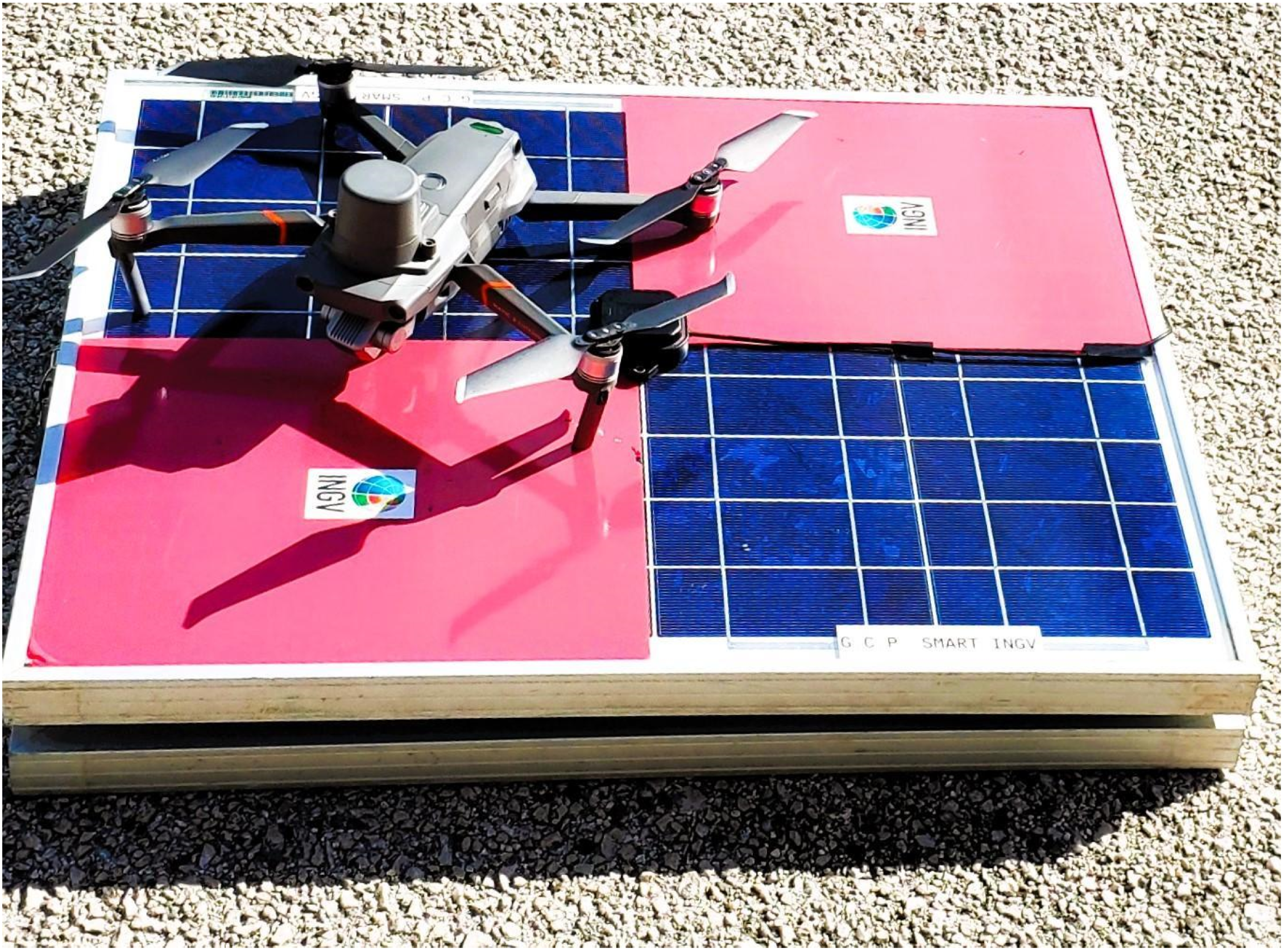
- The S-GCP is used as takeoff and landing points for the drone;
- The S-GCP is used as a GNSS base to acquire raw GNSS data for the post-processing analysis (PPK survey);
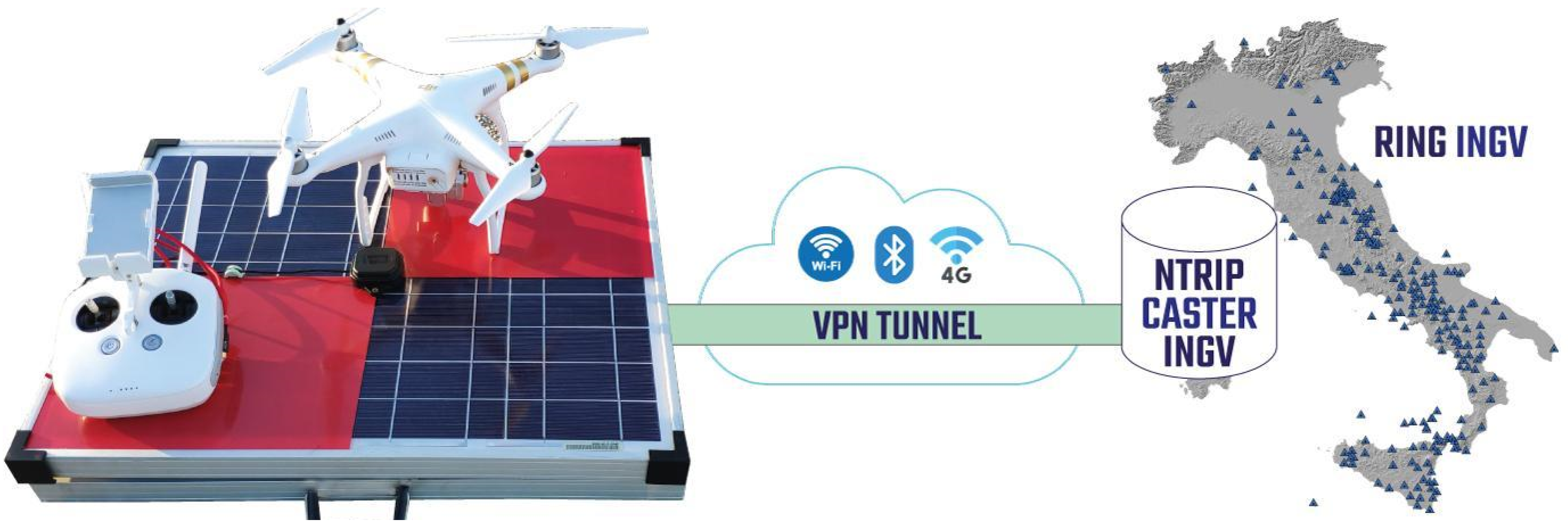
- The S-GCP is used first to receive the real-time correction from CORS (specifically, RING networks, [53]) and then provide it to the drone (RTK survey);
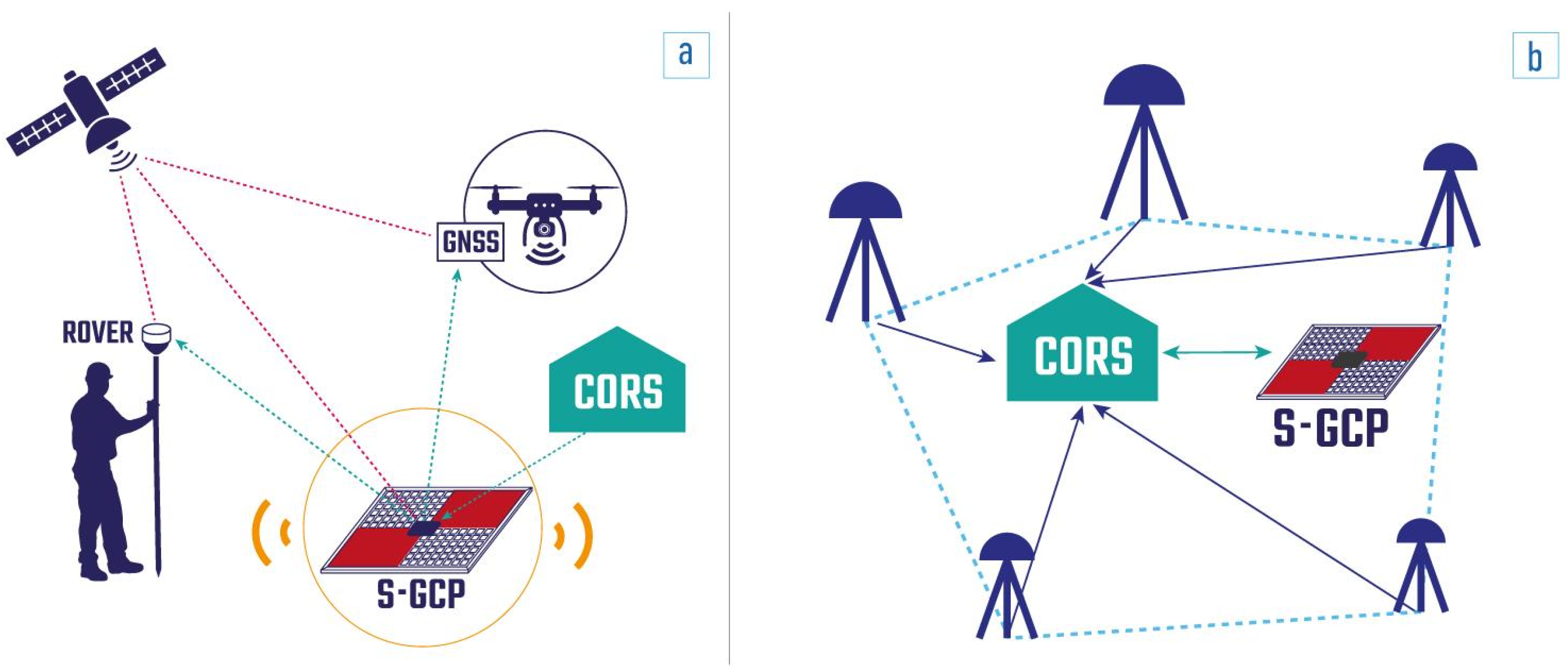
- The S-GCP is used as a GNSS base to provide corrections to the rover in GCP measurements (GCP surveys).
2. Materials and Methods
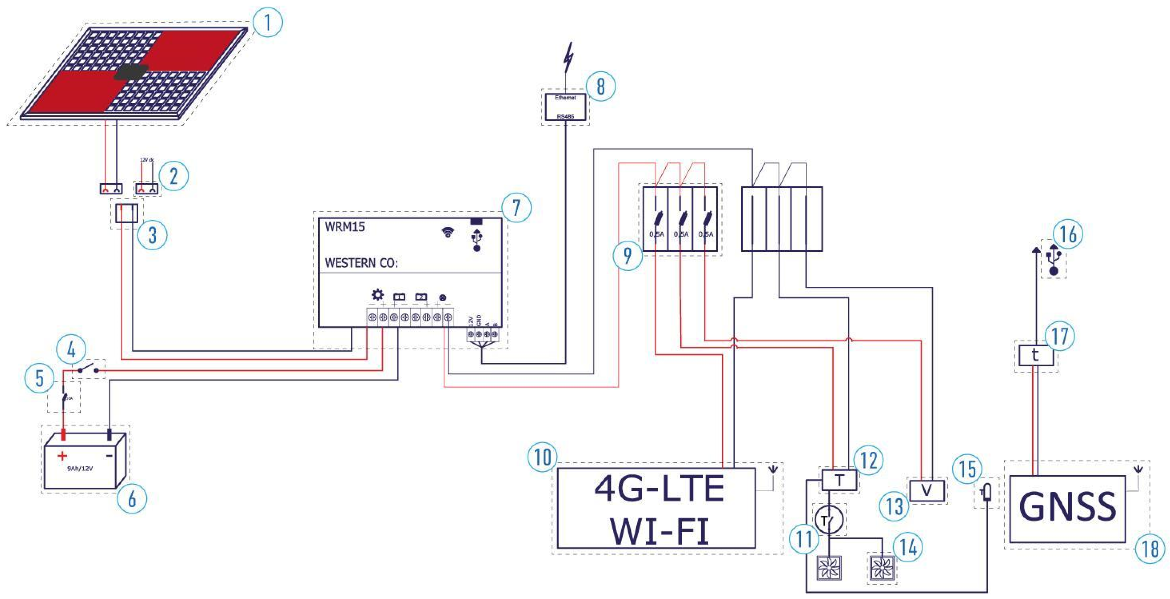
2.1. Power System
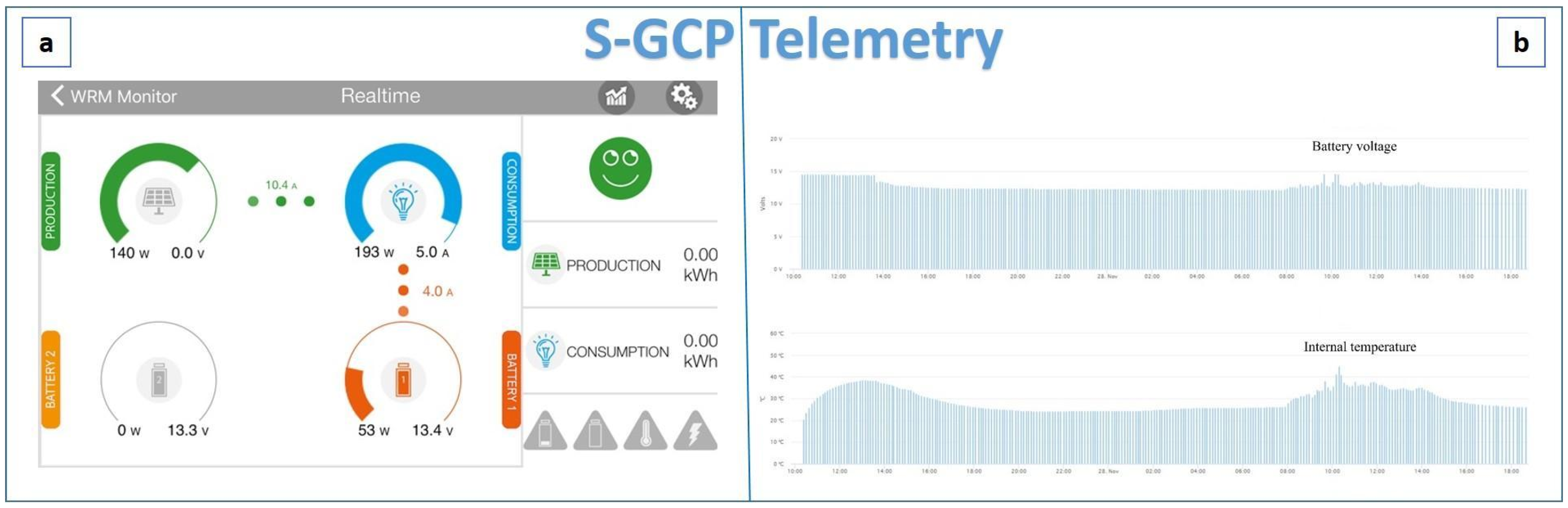
- a web app interface, if the user is close to the S-GCP, through a Bluetooth connection (Figure 3a), ensuring the monitoring and the configuration of different parameters, including the produced power, load power, and battery charging;
- a web portal that can be accessed remotely, as illustrated in [54] (Figure 3b). Thanks to some Python queries that allow for storing, over time, information related to electrical parameters, such as the battery voltage, internal temperature, load current, photovoltaic current, photovoltaic voltage, and battery temperature.
2.2. GNSS Data Acquisition
2.3. Data Transmission
3. Experiments and Results
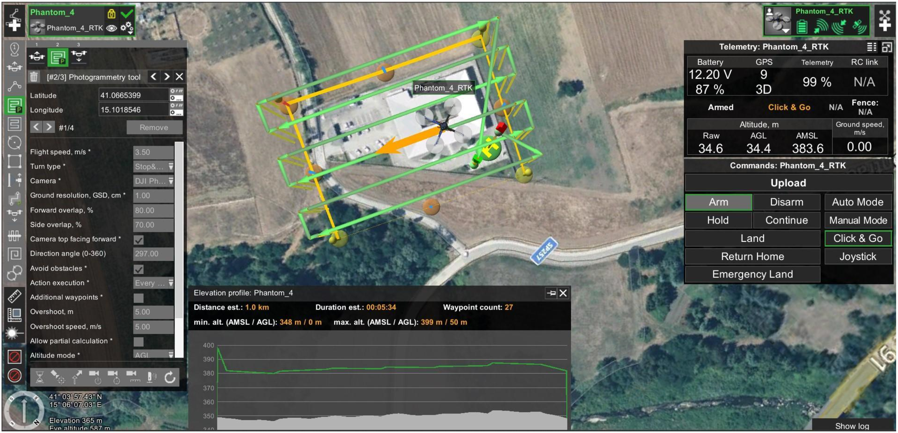
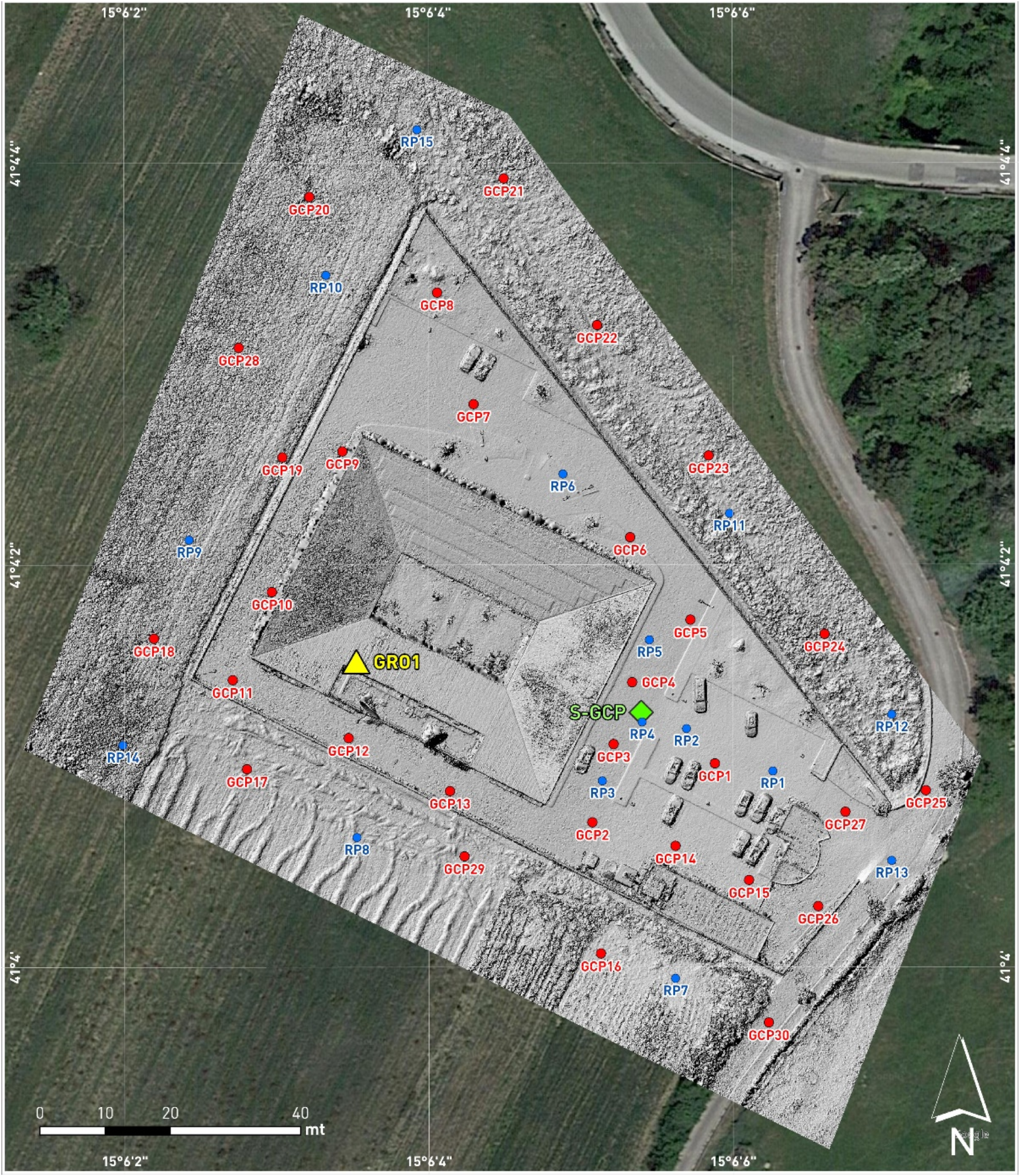
3.1. Test Site, Reference Points, Ground Control Points, and Mission Planning
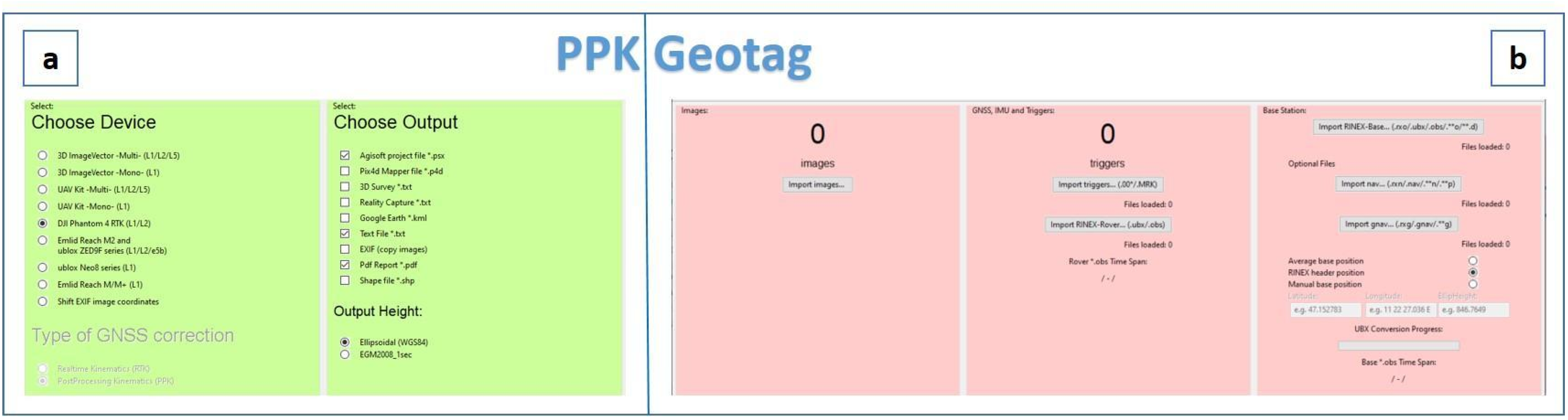
3.2. UAS-PPK Survey
3.3. UAS-RTK Survey
3.4. UAS-GCP Survey
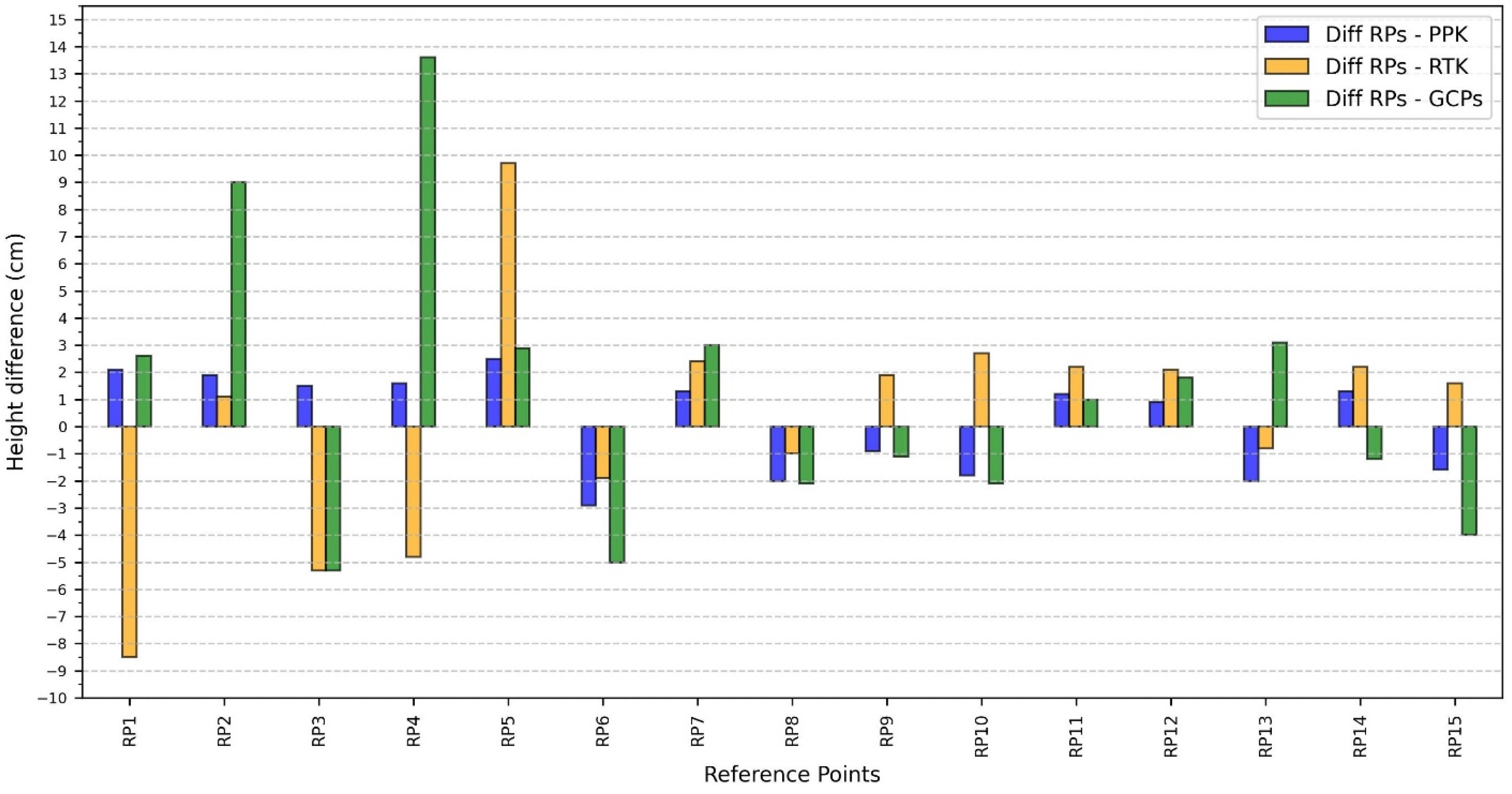
3.5. Survey Results
4. Discussion
5. Conclusions
Author Contributions
Funding
Acknowledgments
Conflicts of Interest
References
- Rakha, T.; Gorodetsky, A. Review of Unmanned Aerial System (UAS) Applications in the Built Environment: Towards Automated Building Inspection Procedures Using Drones. Autom. Constr. 2018, 93, 252–264. [Google Scholar] [CrossRef]
- Kerle, N.; Nex, F.; Gerke, M.; Duarte, D.; Vetrivel, A. UAV-Based Structural Damage Mapping: A Review. ISPRS Int. J. Geo-Inf. 2020, 9, 14. [Google Scholar] [CrossRef]
- Sigala, A.; Langhals, B. Applications of Unmanned Aerial Systems (UAS): A Delphi Study Projecting Future UAS Missions and Relevant Challenges. Drones 2020, 4, 8. [Google Scholar] [CrossRef]
- Colomina, I.; Molina, P. Unmanned Aerial Systems for Photogrammetry and Remote Sensing: A Review. ISPRS J. Photogramm. Remote Sens. 2014, 92, 79–97. [Google Scholar] [CrossRef]
- Pepe, M.; Fregonese, L.; Scaioni, M. Planning Airborne Photogrammetry and Remote-Sensing Missions with Modern Platforms and Sensors. Eur. J. Remote Sens. 2018, 51, 412–436. [Google Scholar] [CrossRef]
- Jiang, S.; Jiang, W.; Wang, L. Unmanned Aerial Vehicle-Based Photogrammetric 3D Mapping: A Survey of Techniques, Applications, and Challenges. IEEE Geosci. Remote Sens. Mag. 2022, 10, 135–171. [Google Scholar] [CrossRef]
- Grubesic, T.H.; Nelson, J.R. UAS Platforms and Applications for Mapping and Urban Analysis. In UAVs and Urban Spatial Analysis: An Introduction; Grubesic, T.H., Nelson, J.R., Eds.; Springer International Publishing: Cham, Switzerland, 2020; pp. 13–29. ISBN 978-3-030-35865-5. [Google Scholar]
- Campana, S. Drones in Archaeology. State-of-the-Art and Future Perspectives. Archaeol. Prospect. 2017, 24, 275–296. [Google Scholar] [CrossRef]
- Adamopoulos, E.; Rinaudo, F. UAS-Based Archaeological Remote Sensing: Review, Meta-Analysis and State-of-the-Art. Drones 2020, 4, 46. [Google Scholar] [CrossRef]
- Saito, H.; Uchiyama, S.; Hayakawa, Y.S.; Obanawa, H. Landslides Triggered by an Earthquake and Heavy Rainfalls at Aso Volcano, Japan, Detected by UAS and SfM-MVS Photogrammetry. Prog. Earth Planet. Sci 2018, 5, 15. [Google Scholar] [CrossRef]
- Heincke, B.; Jackisch, R.; Saartenoja, A.; Salmirinne, H.; Rapp, S.; Zimmermann, R.; Pirttijärvi, M.; Sörensen, E.V.; Gloaguen, R.; Ek, L.; et al. Developing Multi-Sensor Drones for Geological Mapping and Mineral Exploration: Setup and First Results from the MULSEDRO Project. GEUS Bull. 2019, 43. [Google Scholar] [CrossRef]
- Hamshaw, S.D.; Engel, T.; Rizzo, D.M.; O’Neil-Dunne, J.; Dewoolkar, M.M. Application of Unmanned Aircraft System (UAS) for Monitoring Bank Erosion along River Corridors. Geomat. Nat. Hazards Risk 2019, 10, 1285–1305. [Google Scholar] [CrossRef]
- Yang, Q.; Tang, F.; Wang, F.; Tang, J.; Fan, Z.; Ma, T.; Su, Y.; Xue, J. A New Technical Pathway for Extracting High Accuracy Surface Deformation Information in Coal Mining Areas Using UAV LiDAR Data: An Example from the Yushen Mining Area in Western China. Measurement 2023, 218, 113220. [Google Scholar] [CrossRef]
- Koukouvelas, I.K.; Caputo, R.; Nikolakopoulos, K.G.; Kyriou, A.; Famiglietti, N.A. Is the Mesochori Fault a Key Structure for Understanding the Earthquake Activity during the 2021 Damasi Earthquakes in Northern Thessaly, Greece? Geosciences 2023, 13, 331. [Google Scholar] [CrossRef]
- Cirillo, D.; Zappa, M.; Tangari, A.C.; Brozzetti, F.; Ietto, F. Rockfall Analysis from UAV-Based Photogrammetry and 3D Models of a Cliff Area. Drones 2024, 8, 31. [Google Scholar] [CrossRef]
- Menichetti, M.; Roccheggiani, M.; De Guidi, G.; Carnemolla, F.; Brighenti, F.; Barreca, G.; Monaco, C. Sentinel-1 Interferometry and UAV Aerial Survey for Mapping Coseismic Ruptures: Mts. Sibillini vs. Mt. Etna Volcano. Remote Sens. 2023, 15, 2514. [Google Scholar] [CrossRef]
- Salas López, R.; Terrones Murga, R.E.; Silva-López, J.O.; Rojas-Briceño, N.B.; Gómez Fernández, D.; Oliva-Cruz, M.; Taddia, Y. Accuracy Assessment of Direct Georeferencing for Photogrammetric Applications Based on UAS-GNSS for High Andean Urban Environments. Drones 2022, 6, 388. [Google Scholar] [CrossRef]
- Ameri, B.; Meger, D.; Power, K.; Gao, D.Y. UAS Applications: Disaster & Emergency Management. In Proceedings of the ASPRS 2009 Annual Conference, Baltimore, MD, USA, 9–13 March 2009. [Google Scholar]
- Xu, Z.; Yang, J.; Peng, C.; Wu, Y.; Jiang, X.; Li, R.; Zheng, Y.; Gao, Y.; Liu, S.; Tian, B. Development of an UAS for Post-Earthquake Disaster Surveying and Its Application in Ms7.0 Lushan Earthquake, Sichuan, China. Comput. Geosci. 2014, 68, 22–30. [Google Scholar] [CrossRef]
- Mandirola, M.; Casarotti, C.; Peloso, S.; Lanese, I.; Brunesi, E.; Senaldi, I.; Risi, F.; Monti, A.; Facchetti, C. Guidelines for the Use of Unmanned Aerial Systems for Fast Photogrammetry-Oriented Mapping in Emergency Response Scenarios. Int. J. Disaster Risk Reduct. 2021, 58, 102207. [Google Scholar] [CrossRef]
- Hassler, S.C.; Baysal-Gurel, F. Unmanned Aircraft System (UAS) Technology and Applications in Agriculture. Agronomy 2019, 9, 618. [Google Scholar] [CrossRef]
- White, C.T.; Petrasova, A.; Reckling, W.; Mitasova, H. Automated Land Cover Change Detection through Rapid UAS Updates of Digital Surface Models. Int. Arch. Photogramm. Remote Sens. Spat. Inf. Sci. 2020, XLII-3-W11, 155–159. [Google Scholar] [CrossRef]
- Belcore, E.; Piras, M.; Pezzoli, A. Land Cover Classification from Very High-Resolution UAS Data for Flood Risk Mapping. Sensors 2022, 22, 5622. [Google Scholar] [CrossRef]
- Civico, R.; Ricci, T.; Scarlato, P.; Andronico, D.; Cantarero, M.; Carr, B.B.; De Beni, E.; Del Bello, E.; Johnson, J.B.; Kueppers, U.; et al. Unoccupied Aircraft Systems (UASs) Reveal the Morphological Changes at Stromboli Volcano (Italy) before, between, and after the 3 July and 28 August 2019 Paroxysmal Eruptions. Remote Sens. 2021, 13, 2870. [Google Scholar] [CrossRef]
- Martínez, C.; Grez, P.W.; Martín, R.A.; Acuña, C.E.; Torres, I.; Contreras-López, M. Coastal Erosion in Sandy Beaches along a Tectonically Active Coast: The Chile Study Case. Prog. Phys. Geogr. Earth Environ. 2022, 46, 250–271. [Google Scholar] [CrossRef]
- Massaro, L.; Forte, G.; De Falco, M.; Santo, A. Geomorphological Evolution of Volcanic Cliffs in Coastal Areas: The Case of Maronti Bay (Ischia Island). Geosciences 2023, 13, 313. [Google Scholar] [CrossRef]
- Griffiths, D.; Boehm, J. Rapid object detection systems, utilising deep learning and unmanned aerial systems (uas) for civil engineering applications. Int. Arch. Photogramm. Remote Sens. Spat. Inf. Sci. 2018, XLII–2, 391–398. [Google Scholar] [CrossRef]
- Wang, X.; Demartino, C.; Narazaki, Y.; Monti, G.; Spencer, B.F. Rapid Seismic Risk Assessment of Bridges Using UAV Aerial Photogrammetry. Eng. Struct. 2023, 279, 115589. [Google Scholar] [CrossRef]
- Sun, H.; Li, L.; Ding, X.; Guo, B. The Precise Multimode GNSS Positioning for UAV and Its Application in Large Scale Photogrammetry. Geo-Spat. Inf. Sci. 2016, 19, 188–194. [Google Scholar] [CrossRef]
- Stöcker, C.; Nex, F.; Koeva, M.; Gerke, M. Quality Assessment of Combined IMU/GNSS Data for Direct Georeferencing in the Context of UAV-Based Mapping. Int. Arch. Photogramm. Remote Sens. Spat. Inf. Sci. 2017, XLII-2-W6, 355–361. [Google Scholar] [CrossRef]
- Xiang, H.; Tian, L. Method for Automatic Georeferencing Aerial Remote Sensing (RS) Images from an Unmanned Aerial Vehicle (UAV) Platform. Biosyst. Eng. 2011, 108, 104–113. [Google Scholar] [CrossRef]
- Wangfei, Z.; Jianguo, G.; Tianshu, X.; Yanru, H. The Selection of Ground Control Points in a Remote Sensing Image Correction Based on Weighted Voronoi Diagram. In Proceedings of the 2009 International Conference on Information Technology and Computer Science, Kiev, Ukraine, 25–26 July 2009; Volume 2, pp. 326–329. [Google Scholar]
- Guang, Y.; Weili, J. Research on Impact of Ground Control Point Distribution on Image Geometric Rectification Based on Voronoi Diagram. Procedia Environ. Sci. 2011, 11, 365–371. [Google Scholar] [CrossRef]
- Villanueva, J.K.S.; Blanco, A.C. Optimization of ground control point (GCP) configuration for unmanned aerial vehicle (uav) survey using structure from motion (SFM). Int. Arch. Photogramm. Remote Sens. Spat. Inf. Sci. 2019, XLII-4-W12, 167–174. [Google Scholar] [CrossRef]
- dos Santos, D.R.; Dal Poz, A.P.; Khoshelham, K. Indirect Georeferencing of Terrestrial Laser Scanning Data using Control Lines. Photogramm. Rec. 2013, 28, 276–292. [Google Scholar] [CrossRef]
- Jaud, M.; Letortu, P.; Augereau, E.; Le Dantec, N.; Beauverger, M.; Cuq, V.; Prunier, C.; Le Bivic, R.; Delacourt, C. Adequacy of Pseudo-Direct Georeferencing of Terrestrial Laser Scanning Data for Coastal Landscape Surveying against Indirect Georeferencing. Eur. J. Remote Sens. 2017, 50, 155–165. [Google Scholar] [CrossRef]
- Benjamin, A.R.; O’Brien, D.; Barnes, G.; Wilkinson, B.E.; Volkmann, W. Improving Data Acquisition Efficiency: Systematic Accuracy Evaluation of GNSS-Assisted Aerial Triangulation in UAS Operations. J. Surv. Eng. 2020, 146, 05019006. [Google Scholar] [CrossRef]
- Sanz-Ablanedo, E.; Chandler, J.H.; Rodríguez-Pérez, J.R.; Ordóñez, C. Accuracy of Unmanned Aerial Vehicle (UAV) and SfM Photogrammetry Survey as a Function of the Number and Location of Ground Control Points Used. Remote Sens. 2018, 10, 1606. [Google Scholar] [CrossRef]
- Meinen, B.U.; Robinson, D.T. Mapping Erosion and Deposition in an Agricultural Landscape: Optimization of UAV Image Acquisition Schemes for SfM-MVS. Remote Sens. Environ. 2020, 239, 111666. [Google Scholar] [CrossRef]
- Liu, X.; Lian, X.; Yang, W.; Wang, F.; Han, Y.; Zhang, Y. Accuracy Assessment of a UAV Direct Georeferencing Method and Impact of the Configuration of Ground Control Points. Drones 2022, 6, 30. [Google Scholar] [CrossRef]
- Tomaštík, J.; Mokroš, M.; Surový, P.; Grznárová, A.; Merganič, J. UAV RTK/PPK Method—An Optimal Solution for Mapping Inaccessible Forested Areas? Remote Sens. 2019, 11, 721. [Google Scholar] [CrossRef]
- Turner, D.; Lucieer, A.; Wallace, L. Direct Georeferencing of Ultrahigh-Resolution UAV Imagery. IEEE Trans. Geosci. Remote Sens. 2014, 52, 2738–2745. [Google Scholar] [CrossRef]
- Gabrlik, P.; la Cour-Harbo, A.; Kalvodova, P.; Zalud, L.; Janata, P. Calibration and Accuracy Assessment in a Direct Georeferencing System for UAS Photogrammetry. Int. J. Remote Sens. 2018, 39, 4931–4959. [Google Scholar] [CrossRef]
- Chris, M.; Edward, M.; James, S. Manual of Photogrammetry; ASPRS: Bethesda, MD, USA, 2004. [Google Scholar]
- Stott, E.; Williams, R.D.; Hoey, T.B. Ground Control Point Distribution for Accurate Kilometre-Scale Topographic Mapping Using an RTK-GNSS Unmanned Aerial Vehicle and SfM Photogrammetry. Drones 2020, 4, 55. [Google Scholar] [CrossRef]
- Li, X.; Ge, M.; Dai, X.; Ren, X.; Fritsche, M.; Wickert, J.; Schuh, H. Accuracy and Reliability of Multi-GNSS Real-Time Precise Positioning: GPS, GLONASS, BeiDou, and Galileo. J. Geod. 2015, 89, 607–635. [Google Scholar] [CrossRef]
- Famiglietti, N.A.; Cecere, G.; Grasso, C.; Memmolo, A.; Vicari, A. A Test on the Potential of a Low Cost Unmanned Aerial Vehicle RTK/PPK Solution for Precision Positioning. Sensors 2021, 21, 3882. [Google Scholar] [CrossRef]
- Lo, C.F.; Tsai, M.L.; Chiang, K.W.; Chu, C.H.; Tsai, G.J.; Cheng, C.K.; El-Sheimy, N.; Ayman, H. The direct georeferencing application and performance analysis of uav helicopter in gcp-free area. Int. Arch. Photogramm. Remote Sens. Spat. Inf. Sci. 2015, XL-1-W4, 151–157. [Google Scholar] [CrossRef]
- Shahbazi, M.; Sohn, G.; Théau, J.; Menard, P. Development and Evaluation of a UAV-Photogrammetry System for Precise 3D Environmental Modeling. Sensors 2015, 15, 27493–27524. [Google Scholar] [CrossRef]
- Padró, J.-C.; Muñoz, F.-J.; Planas, J.; Pons, X. Comparison of Four UAV Georeferencing Methods for Environmental Monitoring Purposes Focusing on the Combined Use with Airborne and Satellite Remote Sensing Platforms. Int. J. Appl. Earth Obs. Geoinf. 2019, 75, 130–140. [Google Scholar] [CrossRef]
- Cirillo, D.; Cerritelli, F.; Agostini, S.; Bello, S.; Lavecchia, G.; Brozzetti, F. Integrating Post-Processing Kinematic (PPK)–Structure-from-Motion (SfM) with Unmanned Aerial Vehicle (UAV) Photogrammetry and Digital Field Mapping for Structural Geological Analysis. ISPRS Int. J. Geo-Inf. 2022, 11, 437. [Google Scholar] [CrossRef]
- Martínez-Carricondo, P.; Agüera-Vega, F.; Carvajal-Ramírez, F. Accuracy Assessment of RTK/PPK UAV-Photogrammetry Projects Using Differential Corrections from Multiple GNSS Fixed Base Stations. Geocarto Int. 2023, 38, 2197507. [Google Scholar] [CrossRef]
- Avallone, A.; Selvaggi, G.; D’Anastasio, E.; D’Agostino, N.; Pietrantonio, G.; Riguzzi, F.; Serpelloni, E.; Anzidei, M.; Casula, G.; Cecere, G.; et al. The RING Network: Improvements to a GPS Velocity Field in the Central Mediterranean. Ann. Geophys. 2010, 53, 2. [Google Scholar] [CrossRef]
- Castagnozzi, A.; Falco, L.; Cogliano, R. Upgrade del sistema di alimentazione delle stazioni sismiche/GPS e monitoraggio remoto dei parametri elettrici. Rapp. Tec. 2018. [Google Scholar] [CrossRef]
- Takasu, T.; Yasuda, A. Kalman-Filter-Based Integer Ambiguity Resolution Strategy for Long-Baseline RTK with Ionosphere and Troposphere Estimation. In Proceedings of the 23rd International Technical Meeting of the Satellite Division of the Institute of Navigation (ION GNSS 2010), Portland, OR, USA, 24 September 2010; pp. 161–171. [Google Scholar]
- Laoniphon, C.; Thongtan, T.; Satirapod, C. Performance Assessments of Correction Models in GNSS Network-Based RTK Positioning. In Proceedings of the 2021 18th International Conference on Electrical Engineering/Electronics, Computer, Telecommunications and Information Technology (ECTI-CON), Chiang Mai, Thailand, 19–22 May 2021; pp. 2–5. [Google Scholar]
- Rosnell, T.; Honkavaara, E. Point Cloud Generation from Aerial Image Data Acquired by a Quadrocopter Type Micro Unmanned Aerial Vehicle and a Digital Still Camera. Sensors 2012, 12, 453–480. [Google Scholar] [CrossRef] [PubMed]
- Smith, M.W.; Carrivick, J.L.; Quincey, D.J. Structure from Motion Photogrammetry in Physical Geography. Prog. Phys. Geogr. Earth Environ. 2016, 40, 247–275. [Google Scholar] [CrossRef]
- McMahon, C.; Mora, O.E.; Starek, M.J. Evaluating the Performance of sUAS Photogrammetry with PPK Positioning for Infrastructure Mapping. Drones 2021, 5, 50. [Google Scholar] [CrossRef]


| RP | Longitude | Latitude |
Ellipsoidal Height
(m) |
RMS
Longitude (m) |
RMS
Latitude (m) |
RMS
Height (m) |
Antenna
Height (m) | Solution |
|---|---|---|---|---|---|---|---|---|
| RP1 | 15.10173960 | 41.06693724 | 398.501 | 0.010 | 0.011 | 0.010 | 2.134 | FIX |
| RP2 | 15.10158153 | 41.06699612 | 397.791 | 0.010 | 0.010 | 0.010 | 2.134 | FIX |
| RP3 | 15.10142833 | 41.06692386 | 397.548 | 0.030 | 0.039 | 0.036 | 2.134 | FIX |
| RP4 | 15.10150068 | 41.06700504 | 397.582 | 0.011 | 0.010 | 0.011 | 2.134 | FIX |
| RP5 | 15.10151433 | 41.06711872 | 397.596 | 0.010 | 0.011 | 0.013 | 2.134 | FIX |
| RP6 | 15.10135649 | 41.06734742 | 397.703 | 0.014 | 0.011 | 0.015 | 2.134 | FIX |
| RP7 | 15.10156138 | 41.06665081 | 402.284 | 0.012 | 0.013 | 0.011 | 2.134 | FIX |
| RP8 | 15.10097971 | 41.06684580 | 400.009 | 0.010 | 0.012 | 0.014 | 2.134 | FIX |
| RP9 | 15.10067424 | 41.06725649 | 398.734 | 0.011 | 0.013 | 0.011 | 2.134 | FIX |
| RP10 | 15.10092421 | 41.06762236 | 397.260 | 0.019 | 0.011 | 0.025 | 2.134 | FIX |
| RP11 | 15.10166062 | 41.06729281 | 396.962 | 0.010 | 0.014 | 0.013 | 2.134 | FIX |
| RP12 | 15.10195685 | 41.06701512 | 397.679 | 0.012 | 0.014 | 0.011 | 2.134 | FIX |
| RP13 | 15.10195654 | 41.06681348 | 399.632 | 0.014 | 0.011 | 0.018 | 2.134 | FIX |
| RP14 | 15.10055287 | 41.06697345 | 401.143 | 0.011 | 0.010 | 0.011 | 2.134 | FIX |
| RP15 | 15.10109080 | 41.06782385 | 396.144 | 0.010 | 0.012 | 0.011 | 2.134 | FIX |
| GCP | Longitude | Latitude |
Ellipsoidal Height
(m) |
RMS
Longitude (m) |
RMS
Latitude (m) |
RMS
Height (m) |
Antenna
Height (m) | Solution |
|---|---|---|---|---|---|---|---|---|
| GCP1 | 15.10163383 | 41.06694796 | 398.115 | 0.010 | 0.010 | 0.011 | 2.134 | FIX |
| GCP2 | 15.10140970 | 41.06686684 | 397.570 | 0.013 | 0.011 | 0.011 | 2.134 | FIX |
| GCP3 | 15.10143691 | 41.06697751 | 397.603 | 0.010 | 0.011 | 0.013 | 2.134 | FIX |
| GCP4 | 15.10148248 | 41.06706010 | 397.642 | 0.013 | 0.011 | 0.032 | 2.134 | FIX |
| GCP5 | 15.10158908 | 41.06714598 | 397.599 | 0.013 | 0.014 | 0.010 | 2.134 | FIX |
| GCP6 | 15.10147918 | 41.06726008 | 397.729 | 0.011 | 0.011 | 0.013 | 2.134 | FIX |
| GCP7 | 15.10119349 | 41.06744444 | 397.649 | 0.010 | 0.018 | 0.010 | 2.134 | FIX |
| GCP8 | 15.10112709 | 41.06759876 | 397.453 | 0.013 | 0.014 | 0.015 | 2.134 | FIX |
| GCP9 | 15.10095407 | 41.06737923 | 397.395 | 0.011 | 0.010 | 0.011 | 2.134 | FIX |
| GCP10 | 15.10082529 | 41.06718486 | 397.188 | 0.010 | 0.011 | 0.014 | 2.134 | FIX |
| GCP11 | 15.1007533 | 41.0670634 | 396.985 | 0.015 | 0.016 | 0.010 | 2.134 | FIX |
| GCP12 | 15.1009648 | 41.0669831 | 397.176 | 0.013 | 0.015 | 0.013 | 2.134 | FIX |
| GCP13 | 15.10114986 | 41.06691 | 397.276 | 0.020 | 0.025 | 0.020 | 2.134 | FIX |
| GCP14 | 15.10156166 | 41.06683385 | 397.955 | 0.011 | 0.010 | 0.011 | 2.134 | FIX |
| GCP15 | 15.10169574 | 41.06678654 | 398.666 | 0.010 | 0.011 | 0.010 | 2.134 | FIX |
| GCP16 | 15.10142539 | 41.06668525 | 401.606 | 0.016 | 0.013 | 0.013 | 2.134 | FIX |
| GCP17 | 15.10077957 | 41.06694036 | 399.848 | 0.013 | 0.014 | 0.014 | 2.134 | FIX |
| GCP18 | 15.10060978 | 41.06712069 | 399.680 | 0.013 | 0.018 | 0.011 | 2.134 | FIX |
| GCP19 | 15.10084447 | 41.06737075 | 397.923 | 0.011 | 0.010 | 0.011 | 2.134 | FIX |
| GCP20 | 15.10089415 | 41.06773107 | 396.964 | 0.013 | 0.015 | 0.020 | 2.134 | FIX |
| GCP21 | 15.10124942 | 41.0677565 | 396.232 | 0.011 | 0.013 | 0.010 | 2.134 | FIX |
| GCP22 | 15.10141916 | 41.06755329 | 396.566 | 0.019 | 0.018 | 0.017 | 2.134 | FIX |
| GCP23 | 15.10162296 | 41.06737292 | 396.664 | 0.010 | 0.010 | 0.011 | 2.134 | FIX |
| GCP24 | 15.1018342 | 41.06712677 | 397.262 | 0.015 | 0.016 | 0.017 | 2.134 | FIX |
| GCP25 | 15.10201904 | 41.06691067 | 398.621 | 0.014 | 0.014 | 0.013 | 2.134 | FIX |
| GCP26 | 15.10182229 | 41.06675068 | 399.040 | 0.020 | 0.013 | 0.025 | 2.134 | FIX |
| GCP27 | 15.10187161 | 41.06688077 | 399.112 | 0.013 | 0.014 | 0.015 | 2.134 | FIX |
| GCP28 | 15.10076534 | 41.0675224 | 397.567 | 0.011 | 0.010 | 0.011 | 2.134 | FIX |
| GCP29 | 15.10117618 | 41.06681989 | 399.863 | 0.010 | 0.011 | 0.010 | 2.134 | FIX |
| GCP30 | 15.10173165 | 41.06659000 | 404.059 | 0.015 | 0.017 | 0.016 | 2.134 | FIX |
| RP | Longitude | Latitude | RP Height (m) | PPK Height (m) | Diff. RP PPK (m) | RTK Height (m) | Diff. RP RTK (m) | GCP Height (m) | Diff. RP GCP (m) |
|---|---|---|---|---|---|---|---|---|---|
| RP1 | 15.1017396 | 41.06693724 | 398.501 | 398.522 | 0.021 | 398.586 | −0.085 | 398.475 | 0.026 |
| RP2 | 15.10158153 | 41.06699612 | 397.791 | 397.81 | 0.019 | 397.78 | 0.011 | 397.701 | 0.09 |
| RP3 | 15.10142833 | 41.06692386 | 397.548 | 397.563 | 0.015 | 397.601 | −0.053 | 397.601 | −0.053 |
| RP4 | 15.10150068 | 41.06700504 | 397.582 | 397.598 | 0.016 | 397.63 | −0.048 | 397.446 | 0.136 |
| RP5 | 15.10151433 | 41.06711872 | 397.596 | 397.621 | 0.025 | 397.499 | 0.097 | 397.567 | 0.029 |
| RP6 | 15.10135649 | 41.06734742 | 397.703 | 397.732 | −0.029 | 397.722 | −0.019 | 397.753 | −0.05 |
| RP7 | 15.10156138 | 41.06665081 | 402.284 | 402.271 | 0.013 | 402.26 | 0.024 | 402.254 | 0.03 |
| RP8 | 15.10097971 | 41.0668458 | 400.009 | 400.029 | −0.02 | 400.019 | −0.01 | 400.03 | −0.021 |
| RP9 | 15.10067424 | 41.06725649 | 398.734 | 398.743 | −0.009 | 398.715 | 0.019 | 398.745 | −0.011 |
| RP10 | 15.10092421 | 41.06762236 | 397.26 | 397.278 | −0.018 | 397.233 | 0.027 | 397.281 | −0.021 |
| RP11 | 15.10166062 | 41.06729281 | 396.962 | 396.95 | 0.012 | 396.94 | 0.022 | 396.952 | 0.01 |
| RP12 | 15.10195685 | 41.06701512 | 397.679 | 397.67 | 0.009 | 397.658 | 0.021 | 397.661 | 0.018 |
| RP13 | 15.10195654 | 41.06681348 | 399.632 | 399.652 | −0.02 | 399.64 | −0.008 | 399.601 | 0.031 |
| RP14 | 15.10055287 | 41.06697345 | 401.143 | 401.13 | 0.013 | 401.121 | 0.022 | 401.155 | −0.012 |
| RP15 | 15.1010908 | 41.06782385 | 396.144 | 396.16 | −0.016 | 396.128 | 0.016 | 396.184 | −0.04 |
| Average Difference | 0.017 | 0.032 | 0.038 | ||||||
Disclaimer/Publisher’s Note: The statements, opinions and data contained in all publications are solely those of the individual author(s) and contributor(s) and not of MDPI and/or the editor(s). MDPI and/or the editor(s) disclaim responsibility for any injury to people or property resulting from any ideas, methods, instructions or products referred to in the content. |
© 2024 by the authors. Licensee MDPI, Basel, Switzerland. This article is an open access article distributed under the terms and conditions of the Creative Commons Attribution (CC BY) license (https://creativecommons.org/licenses/by/4.0/).
Share and Cite
Famiglietti, N.A.; Miele, P.; Memmolo, A.; Falco, L.; Castagnozzi, A.; Moschillo, R.; Grasso, C.; Migliazza, R.; Selvaggi, G.; Vicari, A. New Concept of Smart UAS-GCP: A Tool for Precise Positioning in Remote-Sensing Applications. Drones 2024, 8, 123. https://0-doi-org.brum.beds.ac.uk/10.3390/drones8040123
Famiglietti NA, Miele P, Memmolo A, Falco L, Castagnozzi A, Moschillo R, Grasso C, Migliazza R, Selvaggi G, Vicari A. New Concept of Smart UAS-GCP: A Tool for Precise Positioning in Remote-Sensing Applications. Drones. 2024; 8(4):123. https://0-doi-org.brum.beds.ac.uk/10.3390/drones8040123
Chicago/Turabian StyleFamiglietti, Nicola Angelo, Pietro Miele, Antonino Memmolo, Luigi Falco, Angelo Castagnozzi, Raffaele Moschillo, Carmine Grasso, Robert Migliazza, Giulio Selvaggi, and Annamaria Vicari. 2024. "New Concept of Smart UAS-GCP: A Tool for Precise Positioning in Remote-Sensing Applications" Drones 8, no. 4: 123. https://0-doi-org.brum.beds.ac.uk/10.3390/drones8040123