Article

HiFly-Dragon: A Dragonfly Inspired Flapping Flying Robot with Modified, Resonant, Direct-Driven Flapping Mechanisms

1
Hefei Institutes of Physical Science, Chinese Academy of Sciences, Hefei 230031, China
2
Science Island Branch, Graduate School of USTC, Hefei 230026, China
*
Author to whom correspondence should be addressed.
Submission received: 30 January 2024 / Revised: 22 March 2024 / Accepted: 25 March 2024 / Published: 28 March 2024

Abstract

:
This paper describes a dragonfly-inspired Flapping Wing Micro Air Vehicle (FW-MAV), named HiFly-Dragon. Dragonflies exhibit exceptional flight performance in nature, surpassing most of the other insects, and benefit from their abilities to independently move each of their four wings, including adjusting the flapping amplitude and the flapping amplitude offset. However, designing and fabricating a flapping robot with multi-degree-of-freedom (multi-DOF) flapping driving mechanisms under stringent size, weight, and power (SWaP) constraints poses a significant challenge. In this work, we propose a compact microrobot dragonfly with four tandem independently controllable wings, which is directly driven by four modified resonant flapping mechanisms integrated on the Printed Circuit Boards (PCBs) of the avionics. The proposed resonant flapping mechanism was tested to be able to enduringly generate 10 gf lift at a frequency of 28 Hz and an amplitude of 180° for a single wing with an external DC power supply, demonstrating the effectiveness of the resonance and durability improvement. All of the mechanical parts were integrated on two PCBs, and the robot demonstrates a substantial weight reduction. The latest prototype has a wingspan of 180 mm, a total mass of 32.97 g, and a total lift of 34 gf. The prototype achieved lifting off on a balance beam, demonstrating that the directly driven robot dragonfly is capable of overcoming self-gravity with onboard batteries.

1. Introduction

Insect-inspired FW-MAVs have been actively investigated in recent decades. The flapping wings not only propel the vehicle to move but also generate aerodynamic forces and torques for attitude control [1] and even sense their surrounding environment by measuring and interpreting the variations of the wing loading, which ensures their exceptional stability and maneuverability at an extremely small scale [2,3]. Several notable bio-inspired flapping wing robots have achieved taking off and hovering in the air, including the Harvard RoboBee [4], the DelFly [5], the Nano Hummingbird [6], the KUBeetle [7], and the BionicOpter [8], inspired by the extraordinary flight capabilities of bees, fruit-flies, hummingbirds, beetles, and dragonflies.
Dragonflies have been recognized as the apex predators of the insect world [9], which have millions of years of adaptation [10], and almost 6000 species with wingspans ranging from 18 mm to 190 mm [11]. By virtue of the tandem wing configuration, they perform superior flight as they can hover in the air, glide with minimal energy consumption, and even maneuver in all directions [12,13,14,15], which makes them master all the flight conditions of helicopters, fixed-wing aircraft, and gliders, which aroused intense interest to study the aerodynamics of dragonflies in different flight modes [16] and develop dragonfly-inspired Micro Air Vehicles (MAVs) [17,18,19]. All four wings of a dragonfly are powered directly by the flight muscles attached to the wing bases; thus, they can independently adjust the flapping amplitude, the stroking phase, and the flapping amplitude offset of each wing to generate aerodynamic forces and torques [20,21,22]. To date, bionic engineers have devoted massive efforts to developing dragonfly-inspired flapping wing air vehicles, but very few untethered prototypes succeed in lifting off. Of these, the BionicOpter [10] from FESTO achieved active stable hovering flight, can maneuver in all directions, hover on the spot, and sail without flapping its wings, and was recognized as the first model capable of handling more flight conditions than helicopters, motorized, and non-motorized gliders combined. The BionicOpter adopts one brushless external rotor motor to drive wings flapping between 15 to 20 Hz and eight servo motors to independently actuate the flapping amplitude and the stroke plane inclination-regulating mechanisms of each wing for attitude control. The complex mechanical systems result in the prototype having a wingspan of up to 63 cm, a body length of 44 cm, and a total weight of up to 175 g, creating a huge gap for miniaturization. All of these prototypes adopt multi-DOF flapping driving mechanisms [23], so extra actuators and mechanisms are necessary, resulting in extremely complicated mechanical systems, a very large weight, and enormous size.
The resonant, direct-driven flapping mechanism is a flapping actuating system that achieves wing flapping motion by controlling the reciprocating rotation of the motors instead of the four-bar linkage or any other transformation mechanisms. In this process, springs are utilized to provide resonance, counteracting the inertial forces and storing energy during flapping. Eliminating the need for extra motor motion transformation and control mechanisms, resonant, direct-driven flapping mechanisms hold potential for light weight and miniaturization. In previous works, DC motors [24] have been tried for actuating the wings flapping directly; [25] studied the effectiveness of resonance for improving the driving efficiency and [26] modeled the dynamic of the resonant, direct-driven flapping. Although the resonant, direct drive mechanism based on a torsion spring is beneficial to simplify the mechanism, spring fatigue failure under resonant conditions tremendously reduces the durability of the direct drive system.
In this work, we introduced a systematic approach for developing a dragonfly-inspired flapping robot propelled by four independent, modified, resonant, direct-driven flapping mechanisms. Compared to the previous works that utilized a single spring to provide resonance, the proposed direct-driven flapping mechanisms in this paper were improved with two asymmetry cascaded torsion springs, which cancel out the spring distortion during stretching and compression. The issue of fatigue failure in torsion springs under alternating load conditions during flapping, which leads to lift damping and reduces the mechanical structure endurance within a few seconds, has been addressed by enhancing the springs’ linearity and system resonance with the proposed asymmetrical cascaded configuration of the torsion springs. The effectiveness of this modification was confirmed through several flapping tests, wherein the resonant, direct-driven flapping mechanism successfully generated a constant lift force of 10 g-force without any lift damping or structural failure. The Printed Circuit Boards (PCBs) of the avionics were designed to function as robot airframes for weight and size reduction. The two pairs of tandem wings were independently actuated by the resonant, direct-driven flapping system, which allows for mimicking the flight behaviors of natural dragonflies to enhance the flapping lift and generate multi-DOF aerodynamic control torques without an extra control mechanism. This research provides a platform for the development of bionic dragonfly aircraft, flapping flight controls, and bionics research.
Section 2 introduces the system design and fabrication methods, including the wings, the resonant flapping drive systems, and the avionics of attitude sensing and flight control. Section 3 introduces the attitude control torque generation strategies. Section 4 demonstrates the flapping propulsion test of the flapping robot. Section 5 concludes the article and reports on the future work of this project.

2. System Design and Fabrication

As shown in Figure 1, the HiFly-Dragon adopts a tandem wing configuration to mimic the flight behaviors of dragonflies. The prototype consists of four main components: the flapping driving mechanisms, the PCBs of the on-bard avionics, four wings, and the batteries. Instead of the complex multilink-based flapping driving mechanisms [5,6,7,27,28], the flapping robot was directly driven by four resonant mechanisms, and all sub-systems were integrated between PCBs for size and weight reduction. It has been verified on a twin-winged direct-driven robot [29] that multi-DOF of vehicle motion and feedback control for attitude can be achieved by the cycle-averaged forces and torques generated by modulating the wing beat velocity within a single flapping cycle without additional actuators or mechanisms.

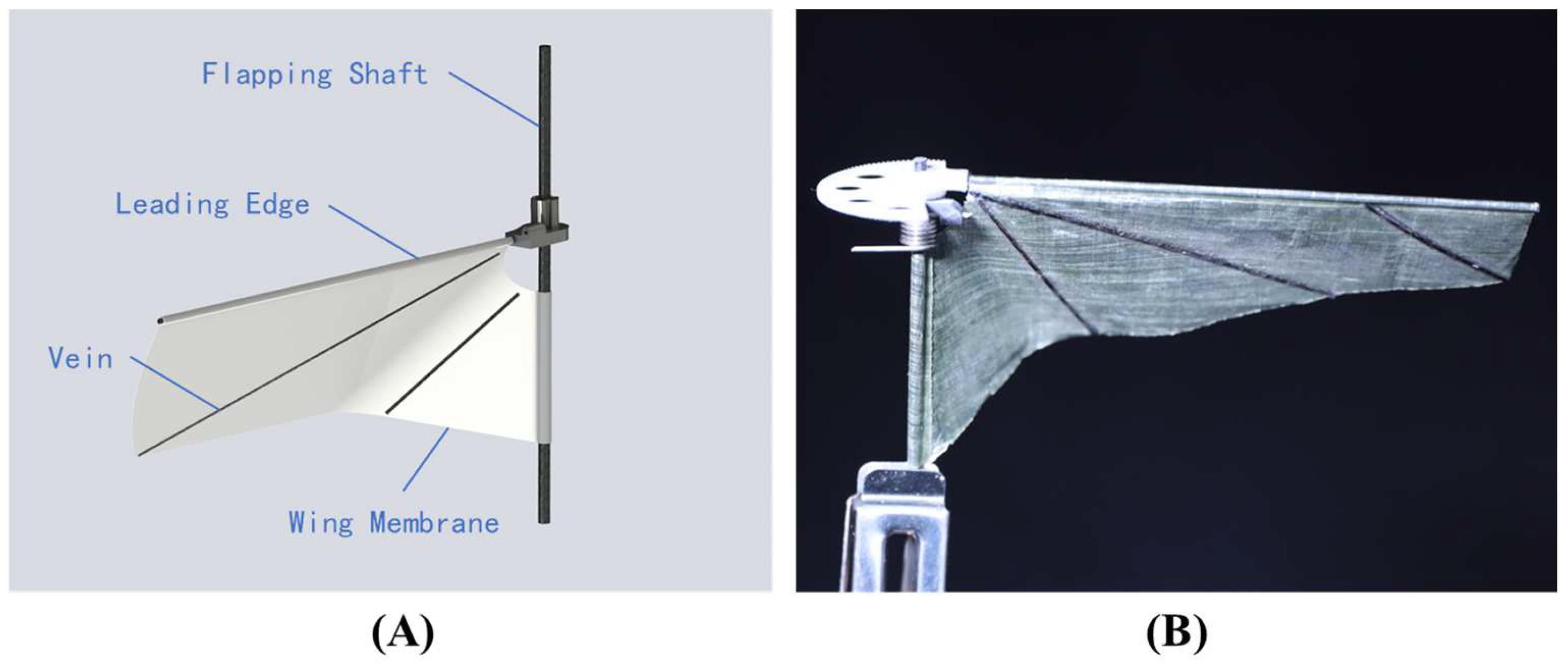
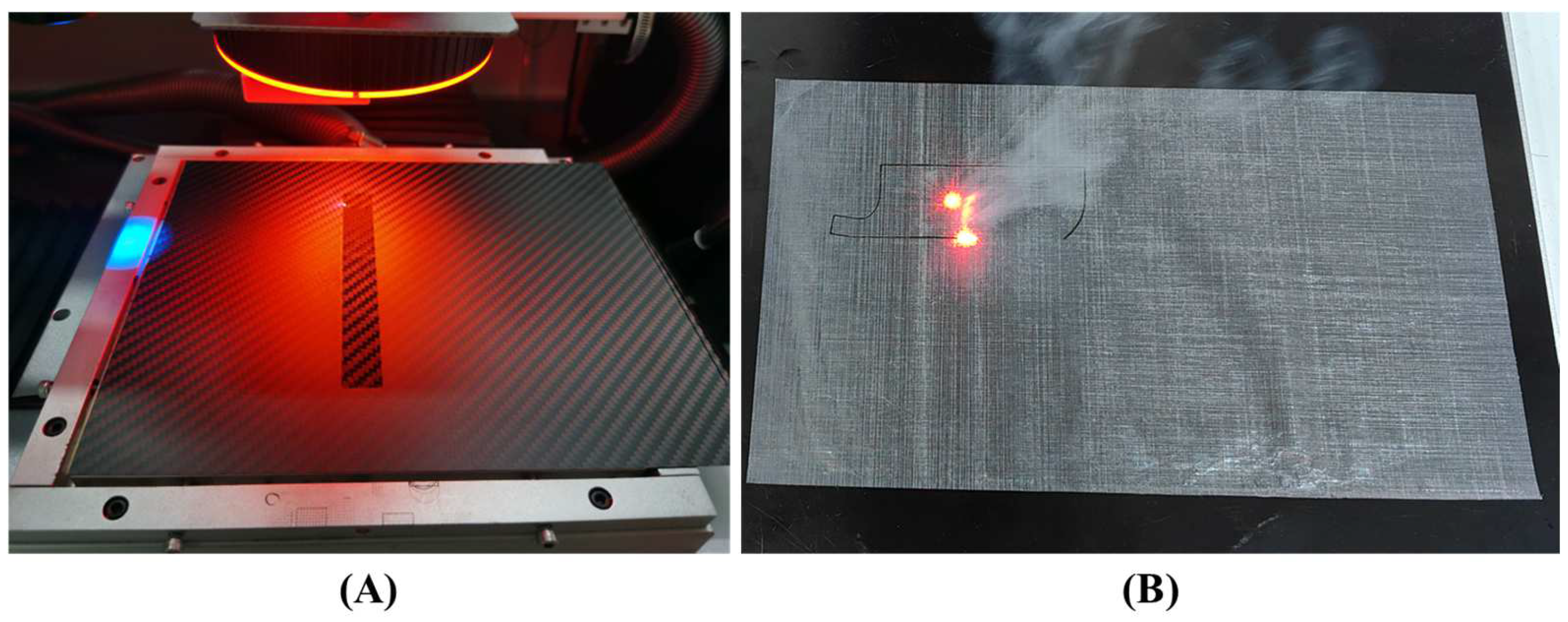
2.1. Wing Design and Manufacturing

The wings of insect-like MAVs can be broadly classified into two categories: flexible wings and rigid wings [30]. The angle between the leading edge and the root edge of the flexible wing results in the wing cambering after assembly, which allows the wing to deform passively, enhancing the aerodynamic efficiency. As shown in Figure 2, the wings of HiFly-Dragon consist of two sleeves, a wing membrane, and wing veins. One sleeve is on the leading edge, accommodating the leading-edge bar made of 0.7 mm carbon fiber rods. The other one is on the root edge, accommodating the root edge bar that functions as the flapping shaft and is made of 1.5 mm carbon fiber rods.
The wing membrane was strengthened by the veins to amplify the aerodynamic performance. The veins were made of a 0.4 mm thick carbon fiber board and cut into 0.6 mm wide ribbons by an ultraviolet picosecond laser (HGTECH, LSP30), as shown in Figure 3. The wing membrane was made of cuben fiber (a laminated high-performance light-weight nonwoven fabric constructed from Ultra High Molecular Weight Polyethylene (UHMWPE, Dyneema, Ohio, USA) fiber monofilaments and polyester), which has great mechanical properties of strength and durability to address the alternating impact load conditions during flapping. The outlines of the wing membrane were automatically cut by a CO2 laser with a high-speed scanning galvanometer (ZK-50W, Zhengke Laser Equipment, Liaocheng, China). Compared to the processing of hand cutting [31], the proposed automatic processing method holds significant advantages in terms of consistency and manufacturing efficiency.
Considering the limited onboard power supply, the prototype demands high propulsion efficiency to generate sufficient thrust while consuming less power. To address that, the trapezoidal airfoil in [32] was adopted to improve the aerodynamic performance with a wing length of R w = 78   mm and a mean chord length of c ¯ = 21   mm . The wings can be driven to flap at a natural frequency with the proper gains of the motor controllers, so that the aerodynamic lift can be tested. As shown in Figure 4, the mean lift of the wing was measured by the F/T sensor (Nano-17, ATI Industrial Automation, North Carolina, USA), indicating that the flapping wing generated a maximum thrust of 11 gf while flapping at a frequency of 28 Hz and an amplitude of about 190°. The power consumption during the measurement was recorded at 0.49 A × 11.1 V = 5.439 Watts with a programmable DC power supply (DP811, RIGOL, Suzhou, China).

2.2. Resonant, Direct-Driven Flapping System

In this paper, the driving torque of the motor was amplified with the gear transmission (with a gear ratio of 10:1), as shown in Figure 5, while the reciprocating of the flapping motion was achieved by the directly bidirectional driving of the motors instead of the four-bar linkage. Additionally, the proposed asymmetry cascaded torsion springs counteract the inertial forces during flapping and store energy, significantly reducing the load on the motor at resonant flapping frequencies. Flapping tests and lift measurements demonstrate that the selected BLDC motor has enough torque to actuate the flapping mechanism and produce sufficient lift for taking off. The BLDC motors were driven by the Field-Oriented Control (FOC) method, and proportional–integral–derivative (PID) controllers were designed for wing trajectory tracking.

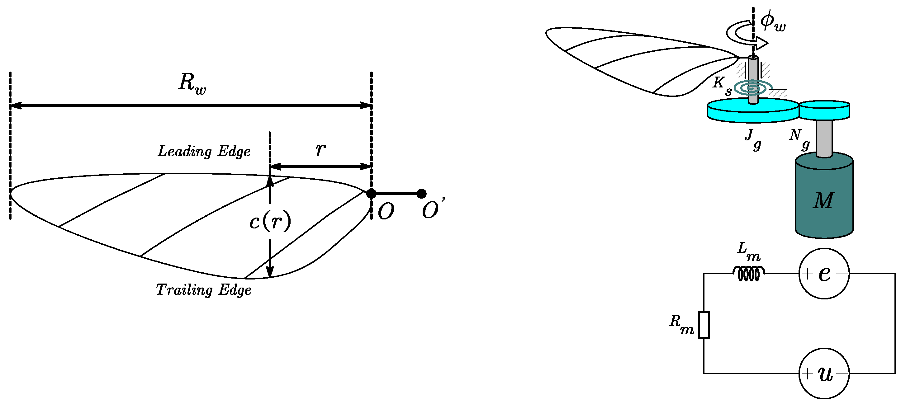
2.2.1. Modeling and Analysis of the Resonant, Direct-Driven Flapping Wing System

To actuate the resonant, direct-driven flapping wing mechanisms, the aerodynamics and mechanical resonance of the flapping wing actuation system have been extensively studied [33,34,35,36,37]. The conceptual design of the flapping wing system is illustrated in Figure 5, in which the flapping wing system has two degrees of freedom of motion: wing stroke angle Φ and passive wing rotation angle α . The model of the flapping wing system is simplified by the quasi-steady aerodynamics assumption with Blade Element Theory (BET), and according to [38], the equation of motion for the system can be given by
J Φ ¨ + C a Φ ˙ + C b Φ ˙ Φ ˙ + K s Φ + T f s i g n Φ ˙ + = K u u
where Φ is the stroke angle in rad, J = J g + N g 2 J m + J w is the total moment of inertia about the wing stroke axis, in which N g 10 : 1 represents the gear ratio and J g , J m , and J w represents the moment of inertia of the gear, the motor rotor, and the wing. C a and C b , which are modeled under the quasi-steady aerodynamic assumption, represent the lumped linear and aerodynamic damping coefficients, respectively. K s is the torsional spring coefficient, T f s i g n Φ ˙ w is the friction, K u is the lumped control input gain, and represents the modeling errors.
To simplify the model of the flapping wing reciprocating motion for resonance effect analysis, the nonlinear friction T f s i g n Φ ˙ w , and modeling errors are abandoned in Equation (1). Regarding the passive wing rotation angle as constant during flapping, the simplified model is given by
J Φ ¨ + C l Φ ˙ + K s Φ w = K u u
where C l is the linearized aerodynamic damping coefficient. The flapping wing system can be treated as a typical second-order spring–mass-damper system, of which the transfer function is given as
G s = Φ s U s = k u / J s 2 + 2 ξ ω n s + ω n 2
The natural frequency is given as
ω n = K s / J
And the damped natural frequency is
ω d = ω n 1 ξ 2
where ξ = C l / 2 J K s . The constant elastic coefficient of the torsion spring is essential for flapping, resonance, and energy recovery. In this paper, the resonance frequency of the whole flapping mechanism with the flapping wings was experimentally verified by sweeping frequency tests. The frequency was set to increase from 0 Hz with 0.5 Hz intervals, and the flapping amplitude increased rapidly as the flapping frequency reached the resonance frequency.

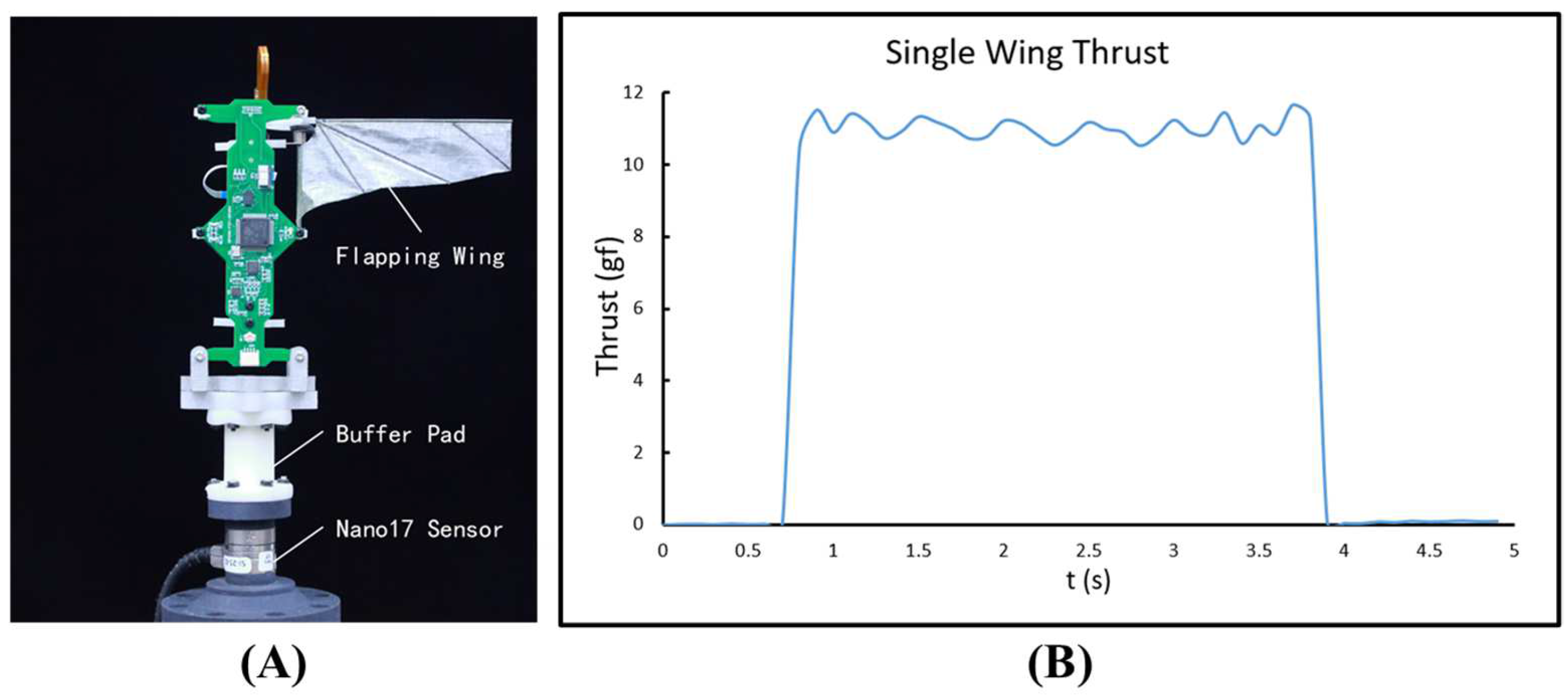
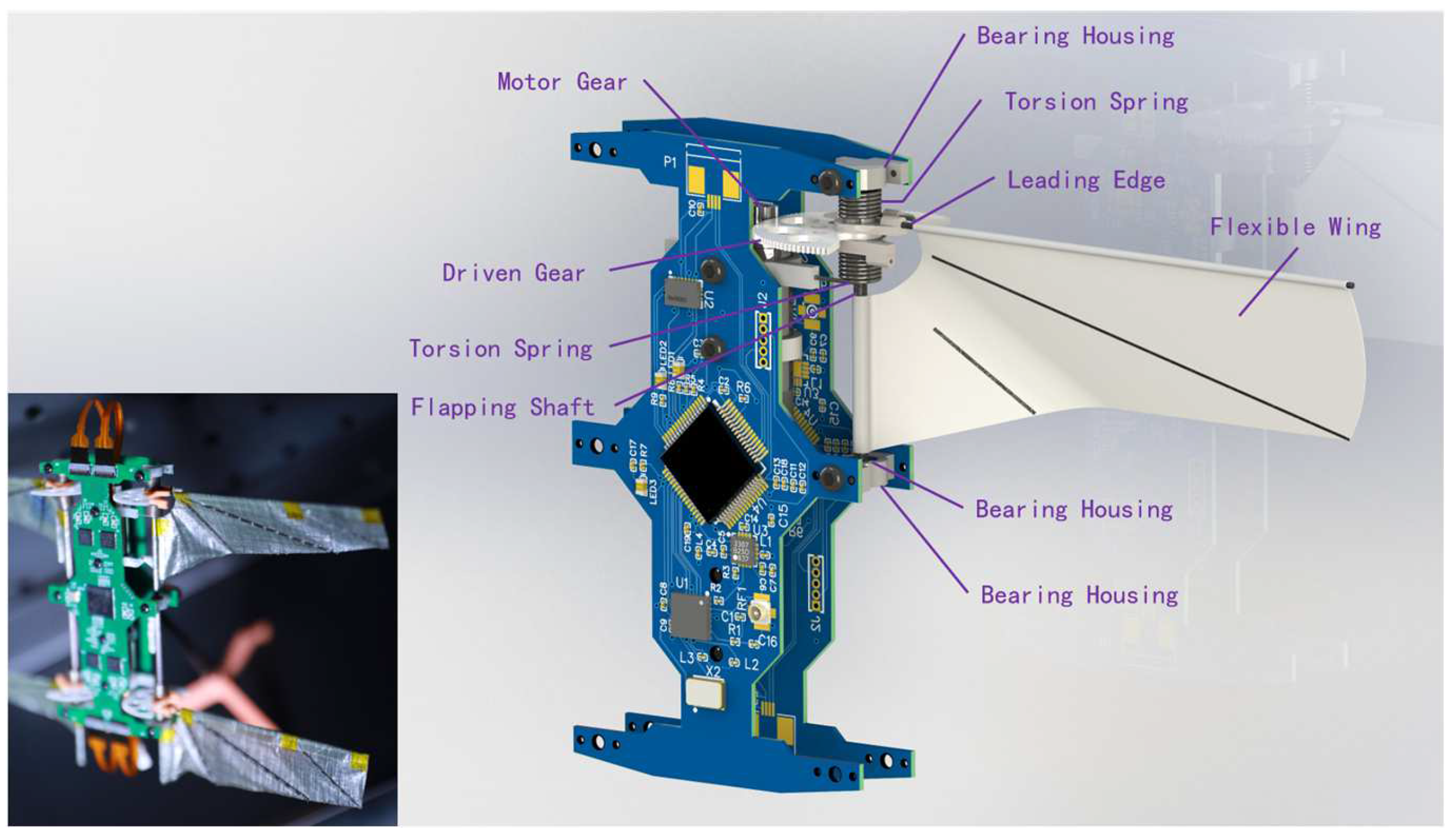
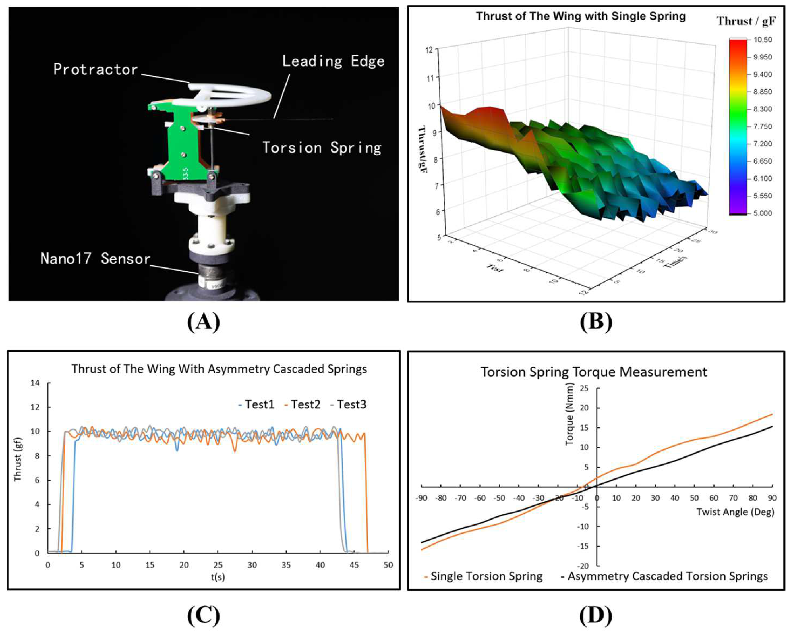
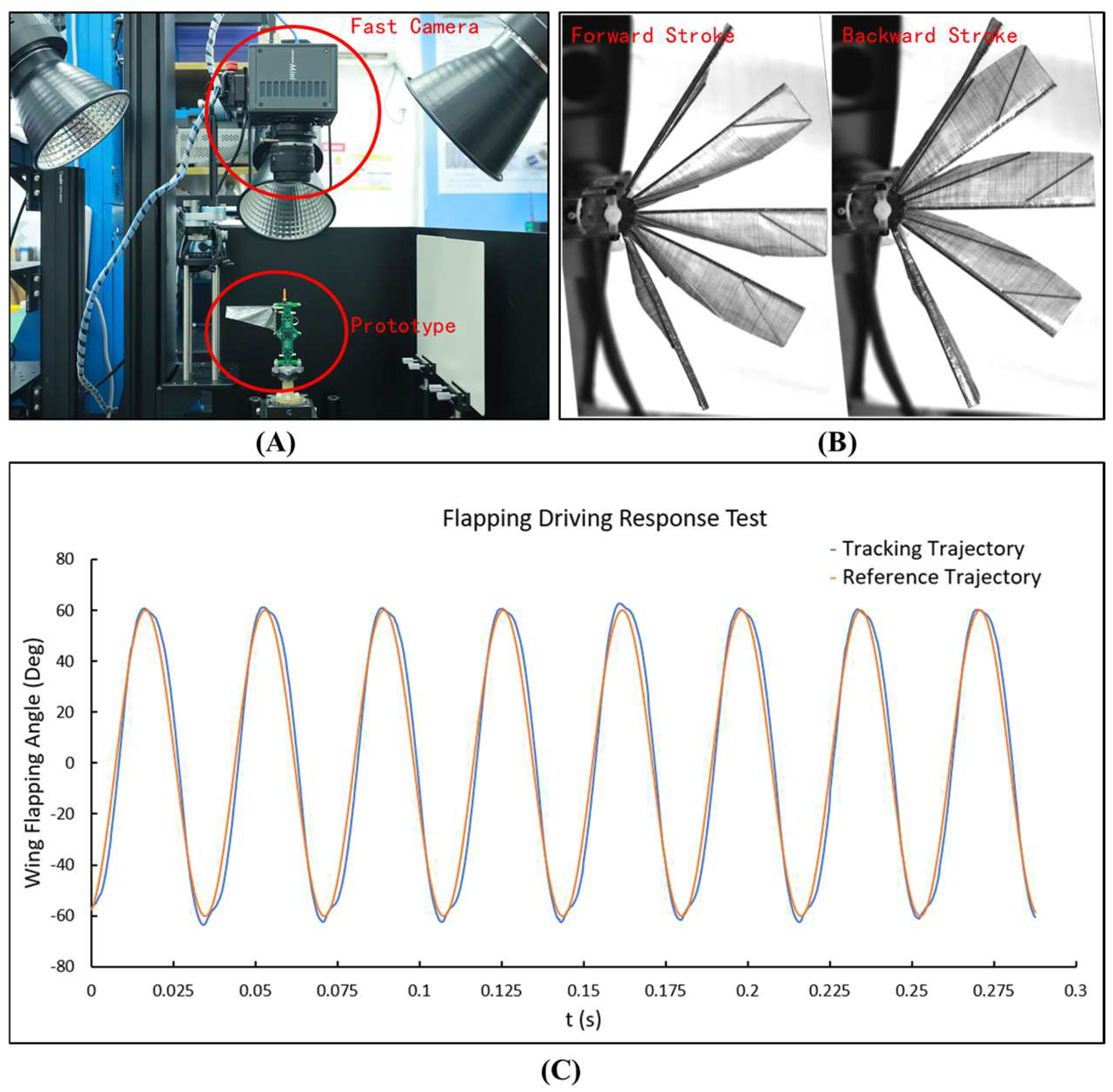
2.2.2. Resonant, Direct-Driven Flapping System Design and Fabrication

As illustrated in Figure 6, the wings were directly driven by four coreless BLDC motors through gear transmissions (10:1 gear ratio, 0.2 modulus). Both of the motor gears and the driven gears were made of polyoxymethylene (POM) by wire cutting. Two ball bearings were installed on both ends of the shafts made from a carbon fiber rod to reduce friction. Each of the wings was connected by two torsion springs mounted on the shaft to achieve resonance. The stiffness of the torsion springs K s illustrated in Figure 5 was well designed to provide a natural frequency of around 28 Hz, which is comparable to the flapping frequency of a natural dragonfly in its hovering state. The stiffness of the torsion springs can be theoretically calculated by
K s = E d 4 64 D n
where E is Young’s modulus, d is the wire diameter, D is the outer diameter, and n is the number of windings. Several series of the torsion springs were customized and tested on the F/T sensor. As shown in Figure 7, the fatigue failure of the torsion spring mentioned in [27] was verified. One stainless steel torsion spring S1 (d = 0.6 mm, D = 4.5 mm, n = 6) was measured and adapted to provide resonance. S1 has significant nonlinearity, resulting in the spring coefficient varying, especially when the torsion angle of the spring exceeds ±50°. As the operating time and usage increased, the lift experienced sharp damping, and the torsion spring broke down during the thirteenth test. To counteract the spring coefficient fluctuations, two cascaded torsion springs of the same type (d = 0.5 mm, D = 5 mm, n = 7) were asymmetrically mounted on the wing, which were tested to be able to enhance the linear region of the torsion springs. The thrust of the modified resonant flapping system was tested, indicating that the flapping system can consistently generate 10 g of lift at a flapping frequency of 28 Hz and an amplitude of 180° for a single wing.

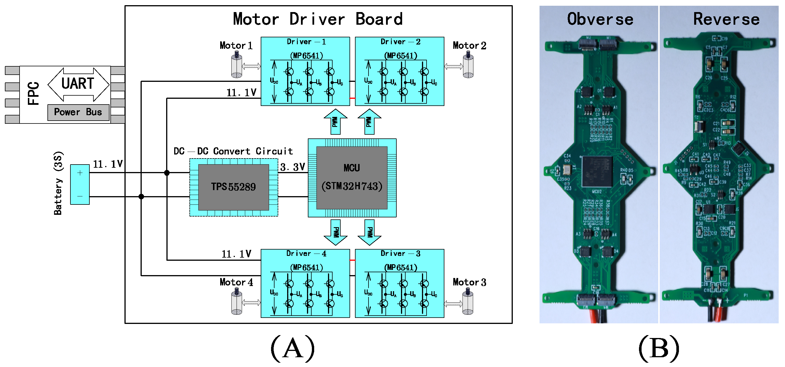
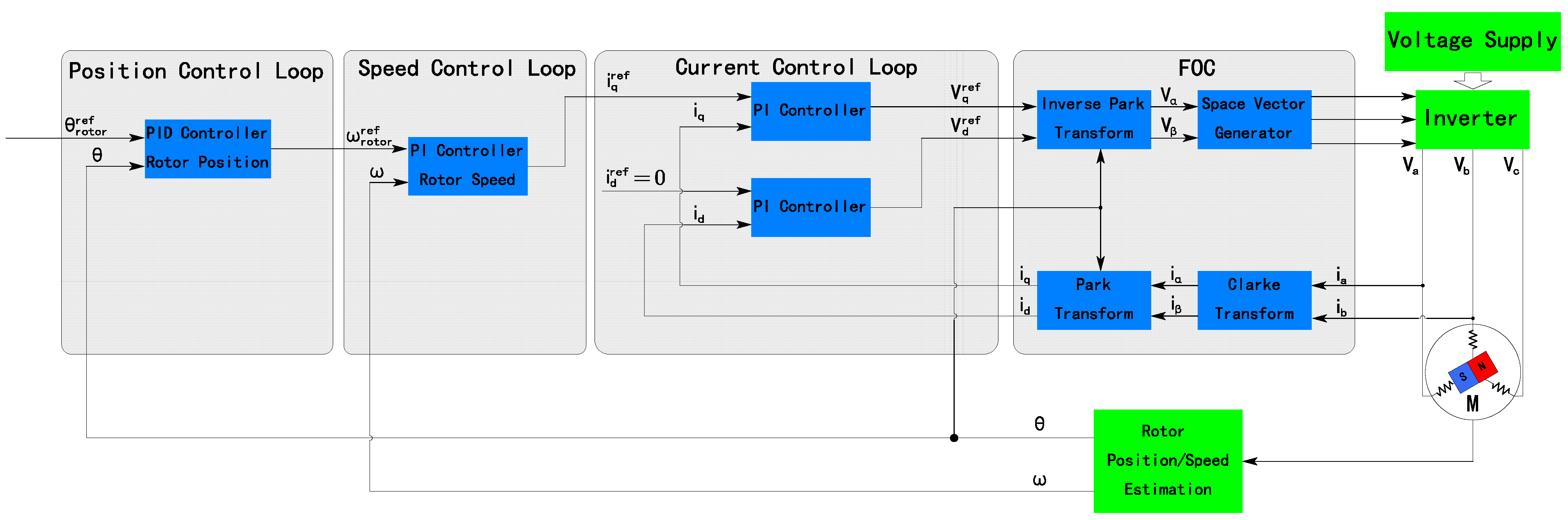
2.2.3. The BLDC Motor Controller Design and Fabrication

In order to enable the wings to achieve flapping motion, the DC motors are driven to oscillate according to the flapping trajectories, and a customized BLDC motor driver hardware system shaped as the airframe was developed, as shown in Figure 8. In this work, three lithium polymer (LiPo) batteries (3.7 V, 100 mAh-30 C, 2.5 g weight, Zoncell, Shenzhen, China) were employed to power the robot’s electronic systems. Four micro-BLDC motors (ECXSP06M-BLKLAHP-6V, Maxon, Sachseln, Switzerland) were used as the actuators. All the motors were embedded with hall magnetic sensors with 256 counts/rev (Maxon, ENX-6MAGA-256IMP) to provide rotational position feedback. This robot platform adopts H-bridge circuits consisting of three pairs of DMOS (double-diffused MOSFET) transistors to power the DC motor. Four DMOS drivers (MP6541, 6 mm × 6 mm, 4.75–40 V gate-source voltage, 8 A maximum output current, Monolithic Power Systems, Washington, USA) were employed for lightweight integration. Sensing resistors were placed to sense the phase current. A power regulator (TPS55289, Texas Instruments, Texas, USA) was adopted to set up the power regulation circuits, which were integrated on the PCB to convert the original battery pack output (11.1 V) to 3.3 V. Three batteries were connected in series to provide a rated voltage of 11.1 V. The power regulation circuits were tested to achieve a maximum output current of 2 A at a constant 3.3 V voltage, which is sufficient to power the logic circuits on the robot platform, including the microcontrol units (MCUs), the inertial measurement unit (IMU) sensor, and the radio frequency communication circuits. An MCU (STM32H743, 8 mm × 8 mm, STMicroelectronics, Genève, Switzerland), which combines a 32-bit ARM Cortex-M7 core, 2 MB of flash memory, and 100 I/O ports and is capable of running at a full frequency of 480 MHz, was selected to satisfy the large computing demands of the multiple DC motors’ FOC algorithms.
To track the wing flapping trajectory precisely, the motor controller over the BLDC direct-driven flapping wing system was developed with the Field-Oriented Control (FOC) strategy, which adjusts the phase voltage with pulse width modulation (PWM, 50 kHz) to synthesize the specific magnetic field vector of the stator. On the basis of that, the speed and torque of the motor can be controlled by adjusting the stator magnetic field vector. The FOC strategy is able to achieve a smoother speed response and smaller torque overshoot than the traditional trapezoidal control method [39]. In this system, the control loop of FOC is closed by a magnetic encoder for position and speed feedback, current sensing resistors for current feedback, and a PID (proportional–integral–derivative) controller for calculating the output, as shown in Figure 9.
Converted by the gear set, the reference position of the BLDC rotor θ r o t o r r e f can be obtained by
θ r o t o r r e f = N g · Φ w
where Φ w is the wing stroke angle in Figure 2. In the rotor position control loop, the error e p can be obtained by
e p = θ r o t o r r e f θ
The rotor position controller was designed as
k p p e p + k i p e p d t + k d p e ˙ p = u p
where k p p , k i p , and k d p are the gains of the position controller. By setting the control output of the position controller u as the reference of the speed controller, the error e s in the speed control loop can be obtained by
e s = u p ω
And the rotor speed controller was designed as
k p s e s + k i s e s d t = u s
The gains of the controllers were experimentally obtained by trial and error.
The motor control loop was implemented at the MCU embedded on the motor driver board at a rate of 2 kHz. The flapping driving system was tested to actuate the flexible wing to flap at a frequency of 28 Hz with an amplitude varying from 100° to 190°. As shown in Figure 10, the wing kinematics were verified to flap at a frequency of 28 Hz and an amplitude of 120° with a head high-speed camera (FASTCAM UX100, resolution 1280 × 1024 pixels, Photron, Tokyo, Japan) at 4000 fps. The flapping angles were measured using Photron PFV4 software, demonstrating that the wing flapping actuation system is able to track the preset flapping trajectories well. The proposed closed-loop flapping actuating control approach based on cascaded PID controllers and the FOC method achieves a larger amplitude and less phase lag compared to the LQR controller and sine wave control approach in [38].

2.3. Onboard Avionics

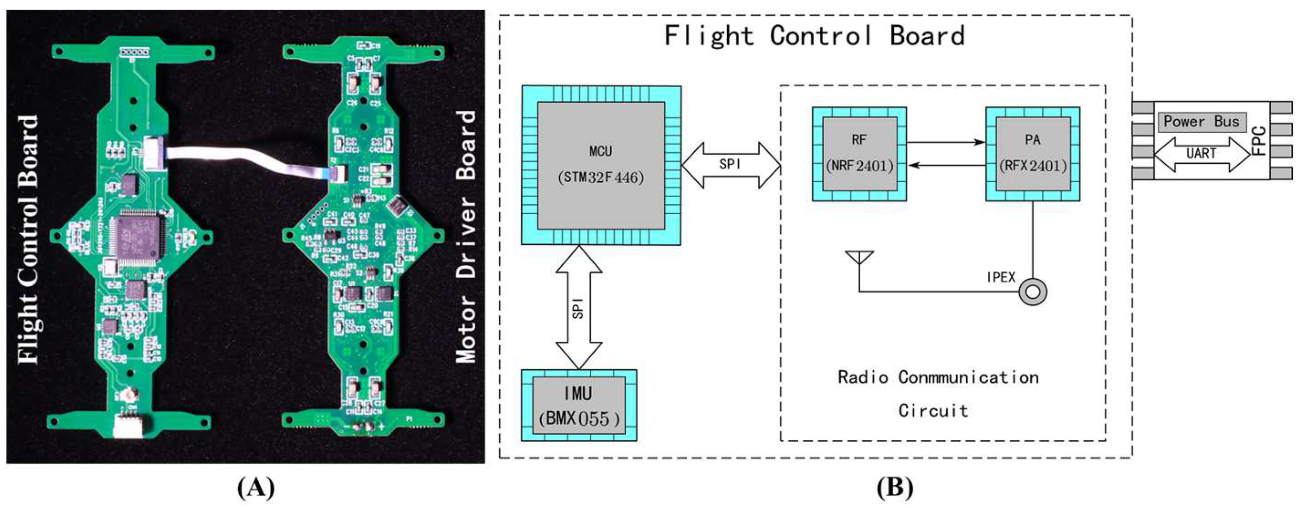
2.3.1. Design of Onboard Avionics Hardware

As shown in Figure 11, the avionics of HiFly-Dragon consist of two parts: the power-driven board and the flight control board. Both the PCBs of the subsystems were shaped as the airframe to mount the mechanical parts. As described in Section 2.2.3, the power-driven board, including the power regulator and the BLDC motor driver, was connected to the batteries to power up the robot. The flight control board was embedded with the functions of computation, attitude sensing, and radio communication. An STM32 MCU (STM32F446RET6, STMicroelectronics, Genève, Switzerland) was used to implement the application algorithms, combining a 32-bit ARM Cortex-M4 core integrating FPU and DSP instructions, 512 KB flash memory, and 64 I/O ports, running at 180 MHz. The robot adopted an inertial measurement unit (IMU) sensor with a small footprint (LGA package 20 pins, footprint 3.0 × 4.5 mm2) and low current consumption—BMX055 (BOSCH), which includes a 3-axis gyroscope, a 3-axis accelerometer, and a 3-axis digital magnetometer to enable the onboard attitude sensing of the robot. A small size and lightweight characteristics are preferred to satisfy SWaP constraints. Additionally, a 2.4 GHz transceiver NRF24L01 (Nordic Semiconductor, Trøndelag, Norway) and a power amplifier (PA) RFX2401C were employed to develop the radio frequency communication circuits for wireless communication, which are able to receive flight commands from the remote-control handle and send flight data to the ground station.

2.3.2. Onboard Attitude Estimation

Suffering from the severe instantaneous oscillations produced by the flapping driving system, developing an attitude estimation algorithm with sufficient accuracy, robustness, and rapidity for attitude estimation is a great challenge, especially with weight limitations preventing the employment of physical buffer materials to reduce noise. The accelerometer and gyroscope were sampled at a rate of 400 Hz. The raw data from the sensors was filtered by second-order Butterworth low-pass filters (400 Hz sample rate, 15 Hz cutoff frequency). Accelerometer signals were used to measure the roll and pitch angles. However, the accelerometers were strongly affected by vibrations caused by the flapping system. The signal noise of the accelerometers cannot be significantly filtered with a higher cutoff frequency (25 Hz) of the filter, resulting in attitude estimation divergence, while the extremely low cutoff frequency (25 Hz) causes nonnegligible hysteresis. To address that, we adopted the error-state Kalman filter (ESKF) method for sensor fusion. As shown in Figure 12, the proposed attitude estimation algorithm was implemented on the flight control board and demonstrated convergence and robustness.

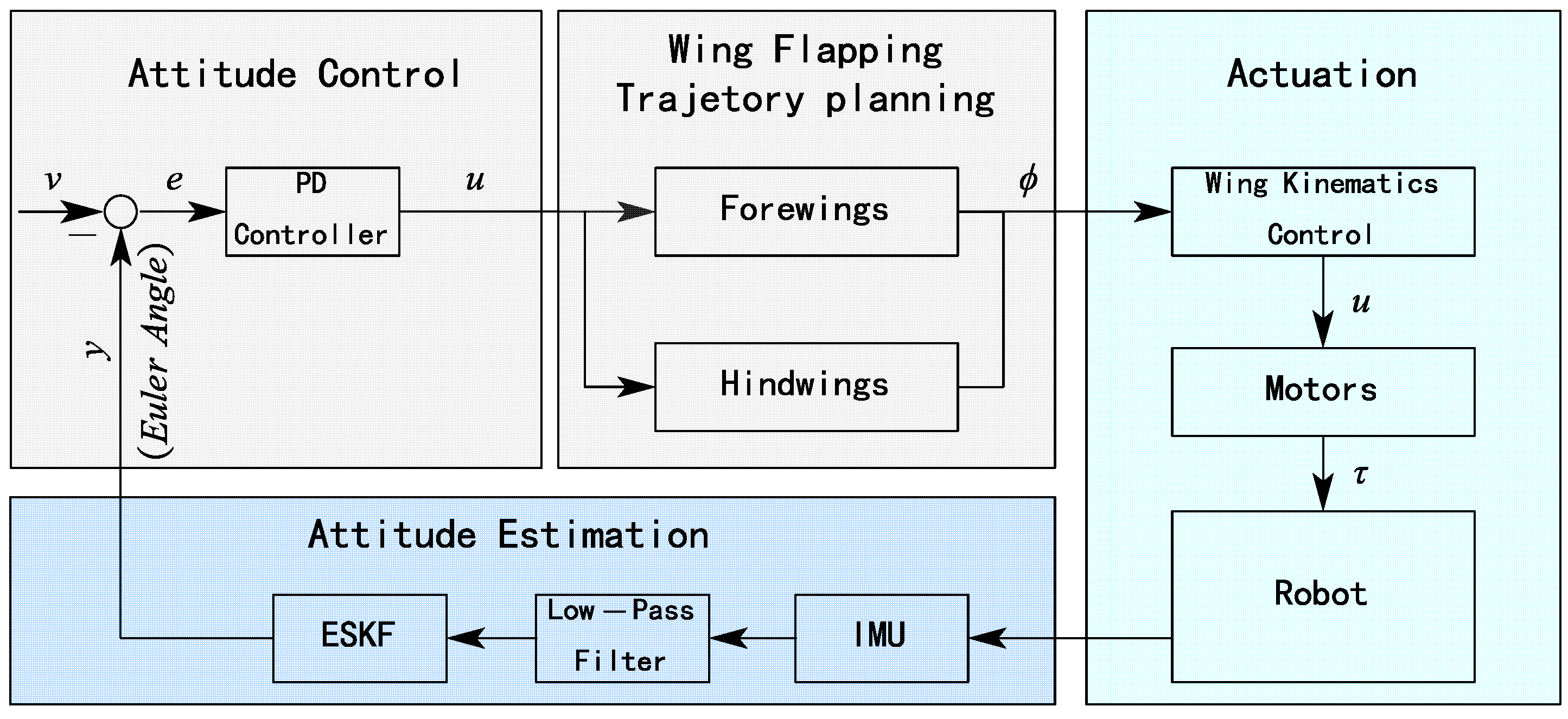
2.3.3. Onboard Flight Attitude Control Algorithm

Feedback control of flight attitude is essential for a sustained stable flight of MAVs, especially for the insect-inspired flapping flying robot due to the inherent instability preventing takeoff. The attitude controller was designed to stabilize the flight attitude of HiFly-Dragon based on the onboard attitude estimation and the capability of generating control torques. The body dynamics of HiFly-Dragon can be preliminarily modeled with the Newton–Euler method as
I ω ˙ + ω × I ω = τ
where I 3 × 3 is the inertia matrix; ω is the body angular velocity in the body frame; and τ is the torque vector in the body coordinate. As shown in Figure 13, the proportion–differentiation (PD) controller is used to control the attitude of roll, pitch, and yaw. The control law is given by
e = v y  
u = k p e + k d e ˙
where e is the attitude error, v is the expected attitude Euler angle, y is the estimated attitude Euler angle, k p is the proportional gain, and the k d is the differential gain. Benefiting from the adequate floating-point arithmetic of STM32F446RET6, the flight attitude control algorithm was programmed and implemented on the flight control board.

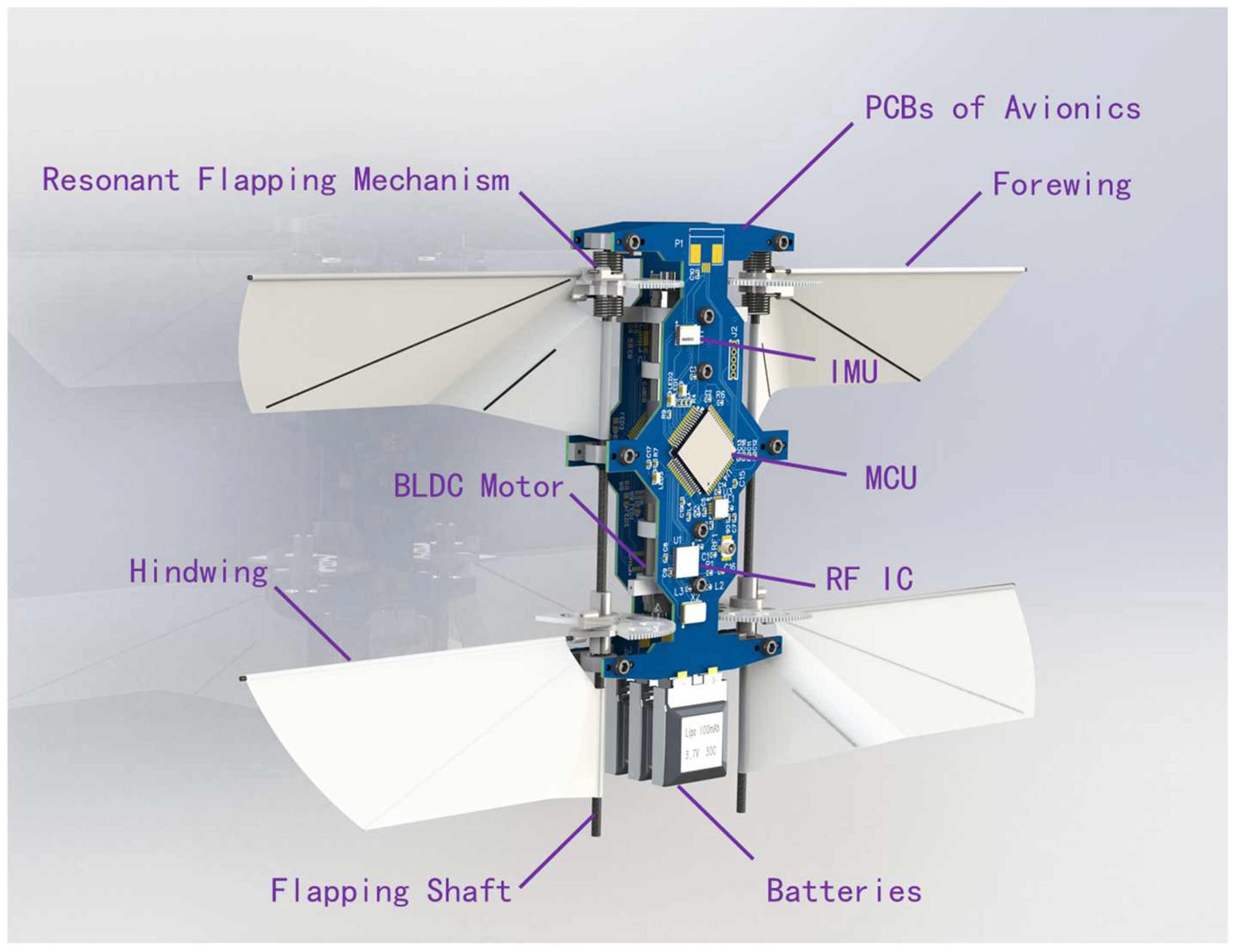
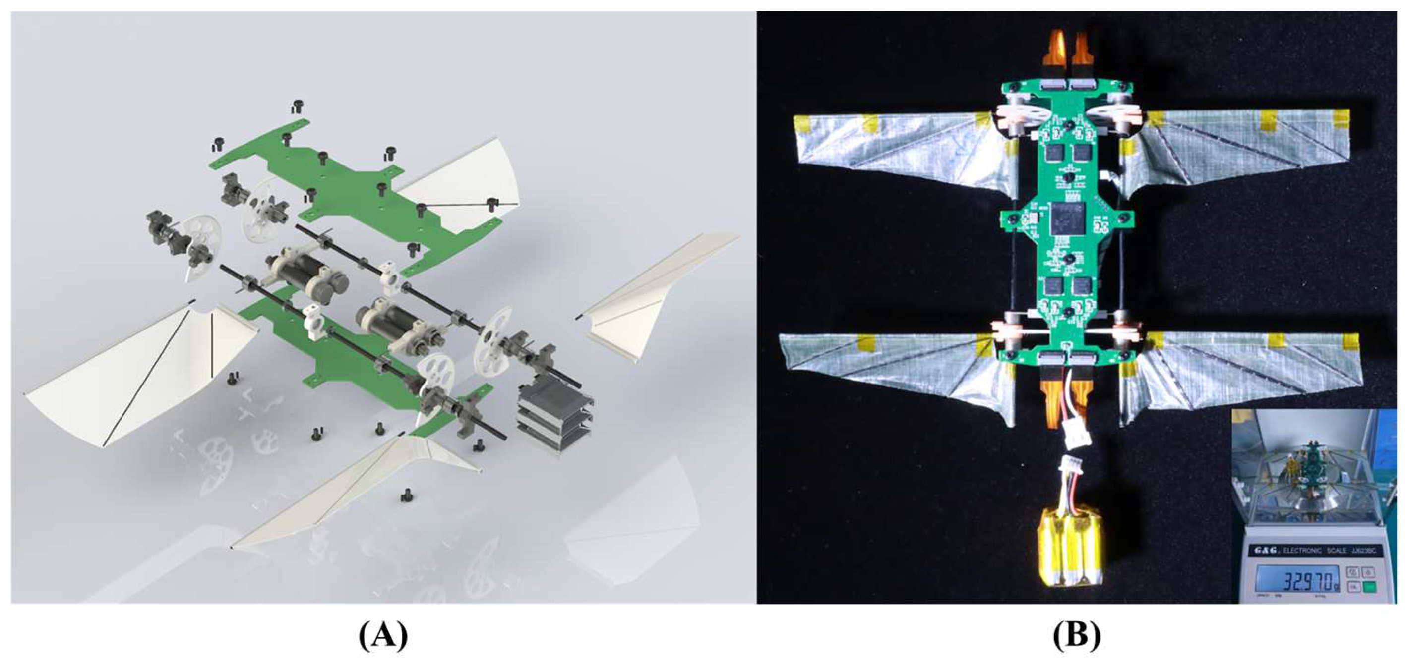
2.4. System Integration of HiFly-Dragon

After several evolutions, the latest prototype has a really thrifty, compact of construction. As illustrated in Figure 14, it is composed of two PCBs, four BLDC motors, resonant flapping mechanisms, flexible wings, batteries, ball bearings, shafts, and parts for connection. All of these parts were fixed between the PCBs using nylon screws. The latest prototype has a wingspan of 180 mm, an empty weight of 25.417 g, and a total mass of 32.97 g (including three batteries) measured using an electronic scale with milligram accuracy (G&G Measurement, JJ623BC), as shown in Table 1.

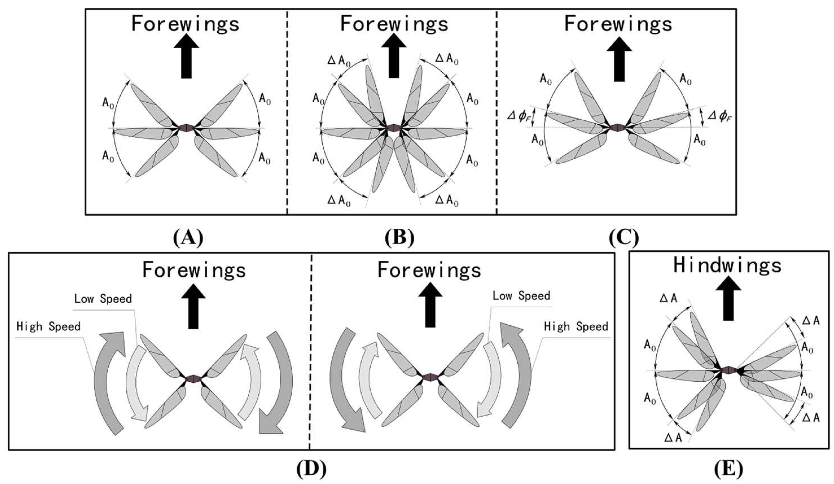
3. Flight Control of HiFly-Dragon

Control Torque Generation

By actuating the wings to flap and tracking cosine-like trajectories, the instantaneous aerodynamic force periodically varies during flapping, resulting in stroke cycle-averaged torques. The flight attitude of HiFly-Dragon can finally be controlled by the stroke cycle averaged torques, including the roll torque, the pitch torque, and the yaw torque. With the tandem wing configuration, the attitude control torques are separately generated by the forewings and the hindwings. Figure 15 visualizes the definition of the flapping trajectories. For the forewings, the flapping trajectories are designed as
F = A 0 + Δ A 0 cos 2 π f t 2 σ + ψ F L + Δ ϕ F ,                             0 t < σ f ( A 0 + Δ A 0 ) cos 2 π f ( t 2 π / f ) 2 1 σ + ψ F R + Δ ϕ F ,       σ f t < 1 f
where ϕ F is the flapping angle, F represents the right ( F = F R ) and left ( F = F L ) wing of the forewings, A 0 is the flapping amplitude, Δ A 0 is the symmetric flapping amplitude changes of the forewings, Δ ϕ F represents the f flapping amplitude offset of the forewings, ψ F L , ψ F R are the phase angles of the forewings, and σ is the flapping split cycle parameter (0 < σ   < 1). To achieve synchronous flapping of forewings, ψ F L is set π rad ahead of ψ F R ( ψ F L = ψ F R + π ). For the hindwings, the flapping trajectories are designed as
H L = A 0 + Δ A cos 2 π f t + ψ H L ϕ H R = A 0 Δ A cos 2 π f t + ψ H R
where Δ A is the asymmetric flapping amplitude changes of the left and right hindwings. The phase angles of the left and right hindwings are, respectively consistent with those of the forewings.
Similarly to the aerodynamic torque generation methods in [27,40], the flight attitude can be controlled with small deviations from the nominal flapping motion parameters in near-hovering conditions. As shown in Figure 14, the lift force F z is controlled by adjusting the symmetric flapping amplitude changes Δ A 0 of the forewings to achieve controllable vertical motion. The pitch torque T y is contributed by the flapping amplitude offset changes of the forewings Δ ϕ F . The roll torque T x is contributed by the asymmetric flapping amplitude changes of the hindwings ΔA. The yaw torque is acquired by the split cycle strategy, and when the flapping split cycle parameter σ slightly varies near 0.5, the yaw torque is controllably generated.

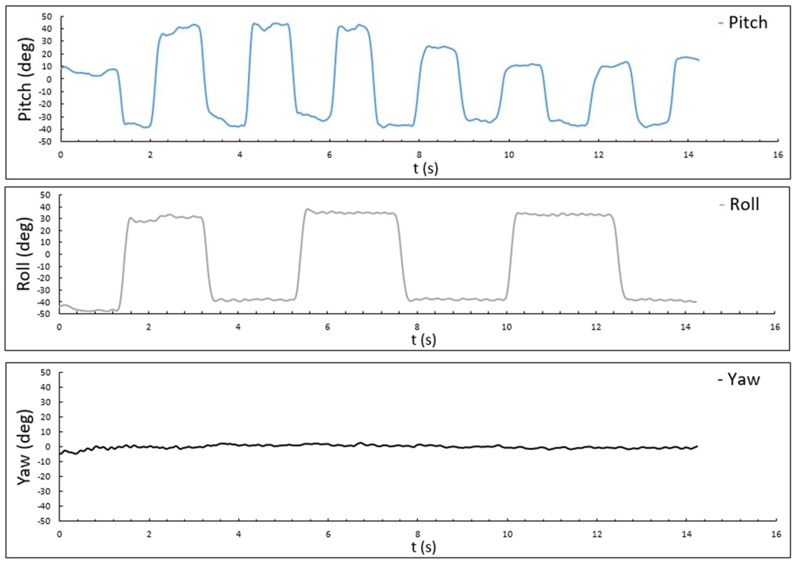
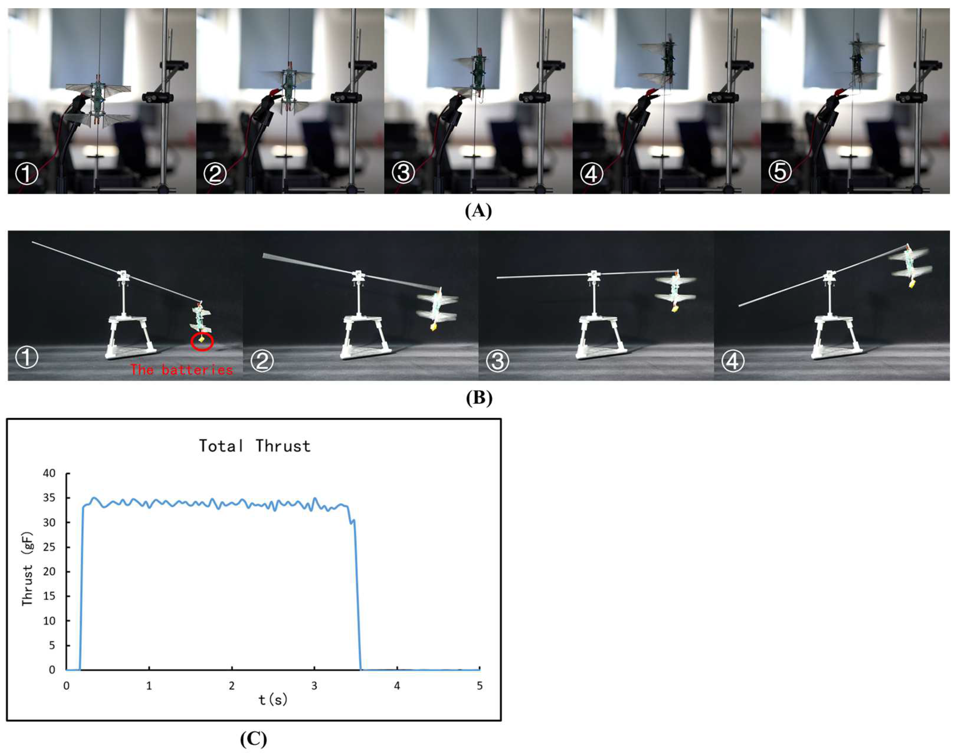
4. Tracked Flight Tests

Tracked flight experiments were designed and implemented to verify whether the proposed resonant, direct-driven system can generate sufficient thrust to take off with onboard power. As shown in Figure 16, a carbon guide rod with a diameter of 4 mm was set to constrain the prototype’s attitude, maintaining an always vertically downward thrust vector, which is consistent with the hovering flight mod. Then, the prototype was installed on the guide rod and powered by an external power supply, and the prototype (not including the batteries, weighing 25.417 g) succeeded in taking off with an amplitude of 150° at the natural frequency of 28 Hz. The batteries were verified to be able to discharge at a constant power of 11.1 V-2 A for more than 27 s using a comprehensive battery tester (JK5530B). During the tracked flight test, the wings were actuated to flap at the take-off amplitude of 168° at 28 Hz powered by onboard batteries, and the total lift of the robot was measured to be over 34 gf with the Nano-17, which is larger than the latest prototype’s 32.97 gf self-gravity. The total take-off power consumption was 1.33 A × 11.1 V = 14.763 W, including the power consumption of the flight control and motor control systems. A balance beam was also used to test the propulsion capability of the robot. The prototype, weighing 32.97 g, took off tethered by the balance beam with all subsystems integrated, as the forewings and hindwings reached an amplitude of 170° at a frequency of 28 Hz.

5. Conclusions

In this paper, we introduced a compact microrobot dragonfly with four tandem independently controllable wings that is directly driven by four modified, resonant, flapping mechanisms integrated on the Printed Circuit Boards (PCBs) of the avionics, called the HiFly-Dragon. The fatigue failure of the torsion springs under alternating load conditions was ameliorated by enhancing the spring linearity with an asymmetrically cascaded torsion spring resonant mechanism, which was verified to maintain a flapping amplitude of 180° at 28 Hz and generate a 10 gf lift for a single wing without attenuation. The indispensable hardware of subsystems for feedback flight control was developed and implemented on the onboard avionics, including attitude sensing, radio frequency wireless communication, four motor controllers, and onboard flight control. All of the parts of the prototype subsystems were integrated on the PCBs, and the robot demonstrated a substantial weight reduction, boasting a 180 mm wingspan and a total weight of 32.97 g (including three cells of LiPo batteries). The total lift of the robot was measured to be up to 34 gf with onboard power. And the robot lifted off powered by onboard batteries on the balance beam. This research provides a microrobot platform with compact structures for the development of bionic dragonfly aircraft, flapping flight control, and bionics research. Our current focus is on testing the attitude control torque responses, tuning the attitude controllers, and flight testing.

Author Contributions

Conceptualization, H.M. and P.G.; methodology, H.M., Y.T. and C.C.; data curation H.M. and P.G.; formal analysis H.M., Q.W., M.P. and H.Y.; visualization H.Y.; project administration H.M., Y.L. and C.C.; software P.G. and Y.T.; writing H.M., C.C. and P.G.; funding acquisition H.M., Y.L. and C.C. All authors have read and agreed to the published version of the manuscript.

Funding

This research was funded by the Strategic Priority Research Program of the Chinese Academy of Sciences, grant number XDA22020503, and was partially supported by the Youth Innovation Promotion Association of the Chinese Academy of Sciences, grant number 2013213.

Institutional Review Board Statement

Not applicable.

Data Availability Statement

The data generated and/or analyzed as well as the source code during the current study are not publicly available due to their use in an undergoing project but could be available from the corresponding author upon reasonable request.

Acknowledgments

The authors would like to gratefully thank Shan Li and Wulin Zhu from USTC Center for Micro—and Nanoscale Research and Fabrication for their help in processing the veins of the wings using the ultraviolet picosecond laser, Chaobo Li from the Institute of Microelectronics of the Chinese Academy of Sciences for his help in processing the micro gears, Shaomin Liu for his help in fabricating the wings, Fan Yuan, Taoran Zhao, and Xiaowei Fu for their help in debugging the programs, and Siqin Ge from the Institute of Zoology, Chinese Academy of Sciences for her help in biological observation experiments. They also appreciate the time and efforts provided by anonymous reviewers and the editors in reviewing this paper.

Conflicts of Interest

The authors declare no conflicts of interest.

References

  1. Hassanalian, M.; Abdelkefi, A. Towards Improved Hybrid Actuation Mechanisms for Flapping Wing Micro Air Vehicles: Analytical and Experimental Investigations. Drones 2019, 3, 73. [Google Scholar] [CrossRef]
  2. Cote, B.; Weston, S.; Jankauski, M. Modeling and Analysis of a Simple Flexible Wing—Thorax System in Flapping-Wing Insects. Biomimetics 2022, 7, 207. [Google Scholar] [CrossRef] [PubMed]
  3. Shyy, W.; Kang, C.; Chirarattananon, P.; Ravi, S.; Liu, H. Aerodynamics, Sensing and Control of Insect-Scale Flapping-Wing Flight. Proc. R. Soc. A 2016, 472, 20150712. [Google Scholar] [CrossRef] [PubMed]
  4. Chirarattananon, P.; Chen, Y.; Helbling, E.F.; Ma, K.Y.; Cheng, R.; Wood, R.J. Dynamics and Flight Control of a Flapping-Wing Robotic Insect in the Presence of Wind Gusts. Interface Focus 2017, 7, 20160080. [Google Scholar] [CrossRef] [PubMed]
  5. Karásek, M.; Muijres, F.T.; De Wagter, C.; Remes, B.D.W.; De Croon, G.C.H.E. A Tailless Aerial Robotic Flapper Reveals That Flies Use Torque Coupling in Rapid Banked Turns. Science 2018, 361, 1089–1094. [Google Scholar] [CrossRef] [PubMed]
  6. Keennon, M.; Klingebiel, K.; Won, H. Development of the Nano Hummingbird: A Tailless Flapping Wing Micro Air Vehicle. In Proceedings of the 50th AIAA Aerospace Sciences Meeting including the New Horizons Forum and Aerospace Exposition, Nashville, TN, USA, 9–12 January 2012; American Institute of Aeronautics and Astronautics: Nashville, TN, USA, 2012. [Google Scholar]
  7. Phan, H.V.; Aurecianus, S.; Kang, T.; Park, H.C. KUBeetle-S: An Insect-like, Tailless, Hover-Capable Robot That Can Fly with a Low-Torque Control Mechanism. Int. J. Micro Air Veh. 2019, 11, 175682931986137. [Google Scholar] [CrossRef]
  8. Gaissert, N.; Mugrauer, R.; Mugrauer, G.; Jebens, A.; Jebens, K.; Knubben, E.M. Inventing a Micro Aerial Vehicle Inspired by the Mechanics of Dragonfly Flight. In Proceedings of the Towards Autonomous Robotic Systems: 14th Annual Conference, TAROS 2013, Oxford, UK, 28–30 August 2013. [Google Scholar]
  9. Riyaz, M. Dragonflies: The Apex Predators of the Insect World. Acad. Lett. 2021, 2, 1365. [Google Scholar] [CrossRef]
  10. Bechly, G.; Brauckmann, C.; Zessin, W.; Groning, E. New Results Concerning the Morphology of the Most Ancient Dragonflies (Insecta: Odonatoptera) from the Namurian of Hagen-Vorhalle (Germany). J. Zool. Syst. 2001, 39, 209–226. [Google Scholar] [CrossRef]
  11. Silsby, J. Dragonflies of the World; CSIRO Publishing: Clayton, VIC, Canada, 2001; ISBN 978-0-643-10087-9. [Google Scholar]
  12. Chahl, J.; Chitsaz, N.; McIvor, B.; Ogunwa, T.; Kok, J.-M.; McIntyre, T.; Abdullah, E. Biomimetic Drones Inspired by Dragonflies Will Require a Systems Based Approach and Insights from Biology. Drones 2021, 5, 24. [Google Scholar] [CrossRef]
  13. Vargas, A.; Mittal, R.; Dong, H. A Computational Study of the Aerodynamic Performance of a Dragonfly Wing Section in Gliding Flight. Bioinspir. Biomim. 2008, 3, 026004. [Google Scholar] [CrossRef]
  14. Wakeling, J.M.; Ellington, C.P. Dragonfly Flight: I. Gliding Flight and Steady-State Aerodynamic Forces. J. Exp. Biol. 1997, 200, 543–556. [Google Scholar] [CrossRef]
  15. Wakeling, J.M.; Ellington, C.P. Dragonfly Flight: II. Velocities, Accelerations and Kinematics of Flapping Flight. J. Exp. Biol. 1997, 200, 557–582. [Google Scholar] [CrossRef] [PubMed]
  16. DiLeo, C.; Deng, X. Design and Experiments of a Dragonfly-Inspired Robot. J. Adv. Robot. 2009, 23, 1003–1021. [Google Scholar] [CrossRef]
  17. Ratti, J.; Vachtsevanos, G. A Biologically-Inspired Micro Aerial Vehicle: Sensing, Modeling and Control Strategies. J. Intell. Robot. Syst. 2010, 60, 153–178. [Google Scholar] [CrossRef]
  18. Zhang, Y.-L.; Li, J.-C.; Zhou, H.; Liu, Y.-Q.; Han, D.-D.; Sun, H.-B. Electro-Responsive Actuators Based on Graphene. Innovation 2021, 2, 100168. [Google Scholar] [CrossRef] [PubMed]
  19. Ozaki, T.; Ohta, N.; Jimbo, T.; Hamaguchi, K. A Wireless Radiofrequency-Powered Insect-Scale Flapping-Wing Aerial Vehicle. Nat. Electron. 2021, 4, 845–852. [Google Scholar] [CrossRef]
  20. Salami, E.; Ward, T.A.; Montazer, E.; Ghazali, N.N.N. A Review of Aerodynamic Studies on Dragonfly Flight. Proc. Inst. Mech. Eng. Part C J. Mech. Eng. Sci. 2019, 233, 6519–6537. [Google Scholar] [CrossRef]
  21. Sun, X.; Gong, X.; Huang, D. A Review on Studies of the Aerodynamics of Different Types of Maneuvers in Dragonflies. Arch. Appl. Mech. 2017, 87, 521–554. [Google Scholar] [CrossRef]
  22. Hamamoto, M.; Ohta, Y.; Hara, K.; Hisada, T. Free-Flight Analysis of Dragonfly Hovering by Fluid–Structure Interaction Analysis Based on an Arbitrary Lagrangian–Eulerian Method. Adv. Robot. 2013, 27, 657–666. [Google Scholar] [CrossRef]
  23. Ratti, J.; Jones, E.; Vachtsevanos, G. Fixed Frequency, Variable Amplitude (FiFVA) Actuation Systems for Micro Aerial Vehicles. In Proceedings of the 2011 IEEE International Conference on Robotics and Automation, Shanghai, China, 9–13 May 2011; IEEE: Shanghai, China, 2011; pp. 165–171. [Google Scholar]
  24. Azhar, M.; Campolo, D.; Lau, G.-K.; Hines, L.; Sitti, M. Flapping Wings via Direct-Driving by DC Motors. In Proceedings of the 2013 IEEE International Conference on Robotics and Automation, Karlsruhe, Germany, 6–10 May 2013; IEEE: Karlsruhe, Germany, 2013; pp. 1397–1402. [Google Scholar]
  25. Nabawy, M.R.A.; Marcinkeviciute, R. Scalability of Resonant Motor-Driven Flapping Wing Propulsion Systems. R. Soc. Open Sci. 2021, 8, 210452. [Google Scholar] [CrossRef]
  26. Zhang, J.; Deng, X. Resonance Principle for the Design of Flapping Wing Micro Air Vehicles. In Proceedings of the 2016 IEEE/RSJ International Conference on Intelligent Robots and Systems (IROS), Daejeon, Republic of Korea, 9–14 October 2016; IEEE: Daejeon, Republic of Korea, 2016; pp. 2412–2418. [Google Scholar]
  27. Jeong, S.; Kim, J.; Choi, S.; Park, J.; Kang, T. Platform Design and Preliminary Test Result of an Insect-like Flapping MAV with Direct Motor-Driven Resonant Wings Utilizing Extension Springs. Biomimetics 2022, 8, 6. [Google Scholar] [CrossRef] [PubMed]
  28. Roshanbin, A.; Abad, F.; Preumont, A. Kinematic and Aerodynamic Enhancement of a Robotic Hummingbird. AIAA J. 2019, 57, 4599–4607. [Google Scholar] [CrossRef]
  29. Tu, Z.; Fei, F.; Deng, X. Untethered Flight of an At-Scale Dual-Motor Hummingbird Robot with Bio-Inspired Decoupled Wings. IEEE Robot. Autom. Lett. 2020, 5, 4194–4201. [Google Scholar] [CrossRef]
  30. Lane, P.; Throneberry, G.; Fernandez, I.; Hassanalian, M.; Vasconcellos, R.; Abdelkefi, A. Towards Bio-Inspiration, Development, and Manufacturing of a Flapping-Wing Micro Air Vehicle. Drones 2020, 4, 39. [Google Scholar] [CrossRef]
  31. Roshanbin, A.; Altartouri, H.; Karásek, M.; Preumont, A. COLIBRI: A Hovering Flapping Twin-Wing Robot. Int. J. Micro Air Veh. 2017, 9, 270–282. [Google Scholar] [CrossRef]
  32. Nan, Y. An Experimental Study on Effect of Wing Geometry of Hummingbird-like Flapping Wing in the Hover. In Proceedings of the International Micro Air Vehicles Conference and Flight Competition 2015 (IMAV 2015), Aachen, Germany, 15–18 September 2015. [Google Scholar]
  33. Roll, J.A.; Cheng, B.; Deng, X. An Electromagnetic Actuator for High-Frequency Flapping-Wing Microair Vehicles. IEEE Trans. Robot. 2015, 31, 400–414. [Google Scholar] [CrossRef]
  34. Doman, D.B.; Oppenheimer, M.W.; Sigthorsson, D.O. Wingbeat Shape Modulation for Flapping-Wing Micro-Air-Vehicle Control During Hover. J. Guid. Control. Dyn. 2010, 33, 724–739. [Google Scholar] [CrossRef]
  35. Zhu, J.; Zhou, C. Aerodynamic Performance of a Two-Dimensional Flapping Wing in Asymmetric Stroke. Proc. Inst. Mech. Eng. Part G J. Aerosp. Eng. 2014, 228, 641–651. [Google Scholar] [CrossRef]
  36. Oppenheimer, M.; Doman, D.; Sigthorsson, D. Dynamics and Control of a Biomimetic Vehicle Using Biased Wingbeat Forcing Functions: Part I—Aerodynamic Model. In Proceedings of the 48th AIAA Aerospace Sciences Meeting Including the New Horizons Forum and Aerospace Exposition; American Institute of Aeronautics and Astronautics, Orlando, FL, USA, 4–7 January 2010. [Google Scholar]
  37. Oppenheimer, M.W.; Doman, D.B.; Sigthorsson, D.O. Dynamics and Control of a Biomimetic Vehicle Using Biased Wingbeat Forcing Functions. J. Guid. Control. Dyn. 2011, 34, 204–217. [Google Scholar] [CrossRef]
  38. Zhang, J.; Cheng, B.; Deng, X. Instantaneous Wing Kinematics Tracking and Force Control of a High-Frequency Flapping Wing Insect MAV. J. Micro-Bio Robot. 2016, 11, 67–84. [Google Scholar] [CrossRef]
  39. Rafiq, M.A.; Sarwer, M.G.; Datta, M.; Ghosh, B.C. Fast Speed Response Field-Orientation Control of Induction Motor Drive with Adaptive Neural Integrator. In Proceedings of the 2005 IEEE International Conference on Industrial Technology, Hong Kong, China, 14–17 December 2005; IEEE: Hong Kong, China, 2005; pp. 610–614. [Google Scholar]
  40. Zhang, J.; Tu, Z.; Fei, F.; Deng, X. Geometric Flight Control of a Hovering Robotic Hummingbird. In Proceedings of the 2017 IEEE International Conference on Robotics and Automation (ICRA), Singapore, 29 May–3 June 2017; IEEE: Singapore, 2017; pp. 5415–5421. [Google Scholar]
Figure 1. Rendering of the HiFly-Dragon flapping flying robot prototype.
Drones 08 00126 g001
Figure 2. Diagram of the flexible flapping wing. Design details (A) and photograph (B) of the prototyped wing. The flapping shaft is a 1.5 mm diameter carbon rod, the leading-edge bar is a 1.5 mm diameter carbon rod, the wing membrane is made of cuben fiber film, and the veins are made of carbon fiber plates.
Drones 08 00126 g002
Figure 3. Processing the veins of the wings with an ultraviolet picosecond laser (A). Processing the wing membrane with a CO2 laser engraver (B).
Drones 08 00126 g003
Figure 4. Experimental setup for thrust measurement using a Nano-17 F/T sensor (A). The lift of the wing was measured at a flapping frequency of 28 Hz and an amplitude near 190° (B).
Drones 08 00126 g004
Figure 5. The diagram of the direct-driven flapping wing actuation system with a resonant mechanism.
Drones 08 00126 g005
Figure 6. Photograph and 3D models of the resonant DC motor direct-driven flapping mechanism.
Drones 08 00126 g006
Figure 7. Photograph of the experimental setup for torsion spring elastic coefficient measurement (A). The thrust tests of the resonant driving system with a single torsion spring (B). The thrust tests of the resonant driving system with asymmetric cascaded torsion springs (C). Curves of the torsion spring torques with respect to the torsion angles (D).
Drones 08 00126 g007
Figure 8. Schematic of the latest onboard motor control board (A). The frame of the PCB board was designed in the shape of the airframes to mount the mechanical structures (B).
Drones 08 00126 g008
Figure 9. The diagram of the BLDC control method based on FOC.
Drones 08 00126 g009
Figure 10. Experimental setup illustration for wing kinematics validation with a high-speed camera (A). Composite image of the flapping motion displaying the wing every 0.0089 s of a stroke cycle (B). Flapping angle response of the driving system as the wing was driven to track a 28 Hz, 60 deg sinusoidal trajectory (C).
Drones 08 00126 g010
Figure 11. The two avionics PCBs were connected with a flexible printed circuit (FPC) cable for power supply and communication (A). Schematic of the flight control board (B).
Drones 08 00126 g011
Figure 12. Euler angle of robot attitude estimated by the ESKF method. The prototype was tilted by hand to verify the response of the sensor fusion algorithm, with the four wings flapping at a frequency of 28 Hz.
Drones 08 00126 g012
Figure 13. Block diagram of onboard flight attitude control.
Drones 08 00126 g013
Figure 14. Exploded view of the robot prototype assembly 3D model (A). Photograph of the latest HiFly-Dragon prototype, including the batteries (B). All the mechanical parts are mounted between two airframe PCBs and fastened with micronylon screws.
Drones 08 00126 g014
Figure 15. Illustration of the parameters of the flapping motion. The flapping amplitude A 0 (A), the symmetric flapping amplitude changes of the forewings Δ A 0 for lift control (B), the flapping amplitude offset of the forewings Δ ϕ F for pitch torque generation (C), the anti-symmetric stroke velocities of forward stroke and backward stroke in a flapping cycle for yaw torque generation (D), the asymmetric flapping amplitude changes of the hindwings Δ A for roll torque generation (E).
Drones 08 00126 g015
Figure 16. Flapping lift test along a carbon guide rod with an external power supply (A). Lift off, tethered by a balance beam, powered by onboard batteries with all sub-systems integrated (B). The total lift of the robot was verified to be over 34 gf (C).
Drones 08 00126 g016
Table 1. Weight breakdown of the prototype. There is no separate physical airframe since the PCBs of the avionics were used to mount all the parts.
ComponentWeight (g)PCT (%)
Power-Driven Board3.50210.62
Flight Control Board2.6938.17
Batteries7.55122.90
Nylon Screws0.1560.47
BLDC Motors10.13230.73
Ball Bearings0.5041.53
Wings0.140.42
Torsional Spring1.3123.98
Others6.9821.17
Total32.97100
Disclaimer/Publisher’s Note: The statements, opinions and data contained in all publications are solely those of the individual author(s) and contributor(s) and not of MDPI and/or the editor(s). MDPI and/or the editor(s) disclaim responsibility for any injury to people or property resulting from any ideas, methods, instructions or products referred to in the content.

