Article

A Novel Approach for the Detection of Geometric- and Weight-Related FSW Tool Wear Using Stripe Light Projection

by
Michael Hasieber
*,
Michael Grätzel
and
Jean Pierre Bergmann
Department of Manufacturing Technology, TU Ilmenau University, 98693 Ilmenau, Germany
*
Author to whom correspondence should be addressed.
J. Manuf. Mater. Process. 2020, 4(2), 60; https://0-doi-org.brum.beds.ac.uk/10.3390/jmmp4020060
Submission received: 12 May 2020 / Revised: 19 June 2020 / Accepted: 21 June 2020 / Published: 23 June 2020
(This article belongs to the Special Issue Friction Stir Welding and Related Technologies)

Abstract

:
Friction stir welding (FSW) has become an up-and-coming joining method with a wide range of industrial applications. Besides the unique weld seam properties, recent investigations have focused on the process-related tool wear of shoulder and probe, which can have detrimental economic and technological effects. This paper presents a systematic quantitative characterization of FSW tool wear using stripe light projection as a novel method to detect weight and form deviations of shoulder and probe. The investigations were carried out with a robotic welding setup in which AA-6060 T66 sheets, with a thickness of 8 mm, were joined by weld seams up to a total length of 80 m. During the experimental tests, geometrical deviations of the tool induced by wear were detected for varying weld seam lengths and different measuring points on the probe and shoulder. It was shown that wear depended on welding length which in turn caused significant deviations and weight losses on shoulder and probe. Furthermore, it was demonstrated that the wear on shoulder and probe can be considered separately. It was found that there is a progressive wear rate on the shoulder and a degressive wear rate on the probe depending on the weld seam length. To demonstrate the negative impact of tool wear on shoulder and probe after 80 m weld seam length, visual and metallographic inspections and tensile tests were carried out to detect resultant irregularities in the weld seam.

1. Introduction

Increasing demands in terms of component complexity, lightweight construction, and the use of new types of materials require development of appropriate welding processes. A promising alternative to conventional welding processes is the friction stir welding technology which was developed at The Welding Institute (TWI) in 1991. In particular, for aluminum applications, friction stir welding exhibits unique advantages compared to conventional fusion welding processes [1]. These include the absence of shielding gases and filler materials, no weld seam preparation as well as the prevention of pores and hot cracks resulting in excellent mechanical weld seam properties. Current applications can be found in the automotive industry [2], E-mobility [3], shipbuilding [4], and in the aerospace industry [5].
The functional element of this technology is a rotating tool consisting of a shoulder and probe. During the welding procedure the rotating tool plunges into the workpiece by the axial force Fz and generates frictional heat which leads to material plasticizing [6]. Thus, the plasticized workpiece material is extruded and displaced by the shoulder and probe from the front to the rear of the tool and forms the weld seam behind the tool below their liquidus temperatures [7]. Finally, the tool is retracted at the end of the joint surfaces.
However, the challenges of friction stir welding (FSW) result from comparative high process forces, reduced welding speeds as well as tool wear for increased welding paths. The main causes for tool wear on the shoulder and probe can be explained by the specific tool–workpiece interactions, which affect tribological loads and thermo-mechanical stresses. As a consequence of FSW tool wear, premature tool failure, process instabilities, and weld seam irregularities such as high surface roughness, incomplete penetration, and wormhole formations may occur. The analysis of areas on the FSW tool with significant wear is an important and relevant topic and thus essential for the further improvement of the procedure as well as for process efficiency. Against this background, a method for the systematic characterization of geometric and weight related wear on the entire FSW tool (probe and shoulder) is presented in this study.
In general, the wear mechanisms in a tribotechnical system can be classified in four categories: adhesion, abrasion, surface fatigue, and corrosive wear. Adhesion is the formation of interfacial adhesive bonds through high local surface pressures and their subsequent material shearing in the base material due to high relative speeds [8,9]. During abrasion, a harder body penetrates the softer surface of the base body and causes wear due to relative movement [8]. Surface fatigue occurs as a result of cyclic mechanical tensions in the surface. In this context cracks appear in the stressed surface layer which can lead to larger material breakouts [8,9]. Corrosive wear is the result of reaction products that are sheared by sliding movement [8].
In the case of FSW, Thompson et al. and Hoßfeld reported that the dominant wear mechanism in FSW of conventional aluminum alloys is adhesion. [10,11]. During the joining of aluminum MMCs (metal–matrix composite), both adhesion and abrasion were the main wear mechanisms as a result of the hard material particles embedded in the matrix material [1,12,13,14]. The penetrating abrasive, which is always harder than the opposing body, can affect micro-groove, micro-chipping, and micro-fracturing through plastic deformation in both two and three-body abrasive wear [8,15]. Eff et al. demonstrated the surface fatigue during the FSW of a pipeline steel X-70 with tools manufactured of tungsten–rhenium (W–Re). The rotation of the FSW tool and the interaction between the tool and the workpiece can cause cyclical mechanical tensions, resulting in cracks in the FSW tool [16]. The interaction of tool and workpiece material due to corrosive wear results are reported in Tarasov et al. and Park et al. [17,18].
In addition to the wear mechanisms during FSW, several investigations have focused mainly on FSW tool wear depending on tool material, joining material, and process parameters such as rotational speed and welding speed. Prado et al. investigated the tool wear in FSW of MMC AA- 6061 T6 + 20% Al2O3 and AA-6061 T6. With tools manufactured by O1 tool steel (tool steel 100MnCrW4, 1.2510), the wear was measured with an increase in rotational speed up to 2500 rpm. At speeds between 1500 and 2000 rpm, a reduction in the percentage of wear on the probe per cm of weld path was found, which was explained by changed material flow conditions. The percentage wear deviation was weight related and was quantified by image pixels (two-dimensional) that were correlated with the tool mass [19]. Shindo et al. and Fernandez et al. extend the study of Prado et al. to take the welding speed into account. At welding speeds ≥6 mm/s, a reduced tool wear can occur, which is attributed to a wear optimized probe shape (self- optimization), in which the material flow removes the surface of the probe through the embedded hard material particles and thus a stationary area without a significant increase in tool wear is obtained [20,21]. It should be noted that in addition to the changed material flow conditions, the energy input also correlates with the welding speed and the reduced wear could accordingly be explained by the reduced frictional power. Liu et al. reported on the quantification of radial wear at different locations of the probe. The tool wear was examined during FSW of AC4A−30% SiC with threaded tools manufactured from sintered tungsten carbide–cobalt (WC−Co), rotational speeds of 1500−2000 rpm and traverse speeds of 25−150 mm/min. The results show that the probe length was changed slightly in contrast to the radial wear of the probe. The maximum radial deviation of about 27% to the initial state was measured with an optical light microscope about one-third of the probe length, measured from the probe root [22]. The investigations of Thompson et al. depict the dependence of tool wear on the tool material. The aim was to characterize the wear of W-based tools (tungsten) during FSW of high strength steel (HSS). It could be shown that tungsten–hafnium carbide (W–HfC) has a higher strength and wear resistance at high temperatures than tungsten–rhenium (W–Re) and tungsten–lanthanum oxide (W–La2O3). The wear was characterized qualitatively by cross sections of the FSW tools, using light microscopy and quantitatively by measuring the probe with profilometry [10]. The study of Prater et al. evaluated the effectiveness of harder tool materials during the FSW of Al359 + 20% SiC and Al359 + 30% SiC. The tool materials considered were O1 tool steel, cemented carbide (WC–Co) of micrograin as well as submicrograin varieties and WC–Co coated with diamond. Through the weight related wear deviation measured with a scale it was found that a harder tool material can extend tool life [23]. However, harder tool materials are also more brittle and tools tend to fail prematurely under cyclical mechanical tensions and typical FSW forces [10]. Thus, a convenient tool material should have a sufficient fracture toughness at room and process temperature [13].
Sahlot et al. examined tool wear in FSW of copper–chromium–zirconium (CuCrZr) alloy with H13 tool steel (hot-working steel X40CrMoV5-1, 1.2344) and showed an increasing wear at the shoulder and probe for rotational speeds up to 1200 rpm. The tool wear was measured and quantified by comparing the geometric deviations of probe and shoulder from the initial state with the worn-out tool using light microscope images [24]. Wieckowski et al. 2019 investigated the tool wear for lap joints in dependence of the quality and the length of the weld seams (up to 200 m). The investigations were carried out with a plate thickness of 1 mm for the top sheet and 0.8 mm for the bottom sheet for FSW of AA-7075 T6 with tools manufactured from H13 tool steel and MP-159 alloy (Ni–Co). The highest wear in the experimental investigation was observed at the probe radius on the FSW tool made of MP-159 [25]. To increase the wear resistance of FSW tools, the tools can be coated, or hard materials can be implanted selectively into the metal matrix. Schüddekopf et al. found a significant reduction of the wear in FSW of AA-6082 T6 with tools manufactured by H13 tool steel and boron carbide (B4C) implants. Compared with a conventional FSW tool manufactured from H13 tool steel, the tool with the implants showed a reduction in wear at the probe diameter of about 30% and at the thread angles of about 70% [26].
In summary, a large number of investigations focused mainly on how FSW tool wear depends on tool material, joining material and process parameters. The analysis of wear on the FSW tool was carried out geometrically or weight related. During the geometrical analysis, the FSW tool was usually destroyed and the wear was examined by two-dimensional cross sections, so that no further examinations could be made [10,16,22,23,24]. The weight related analysis of wear enabled a non-destructive wear measurement on the FSW tool, but areas with significant tool wear could not be identified [12,19,20,21,23].
The aim of this paper is to present a systematic and quantitative characterization of stripe light projection as a novel nondestructive testing (NDT) method to detect weight and form deviations of shoulder and probe. This enables the FSW tool wear to be characterized in a three-dimensional, nondestructive way and allows the identification of contours and areas with significant wear. With this approach it is possible to determine weight related deviations due to wear separately for each area on the shoulder and probe without using a scale. To demonstrate the negative impact of tool wear on the shoulder and probe, the study also examined the resulting weld seam quality.

2. Materials and Methods

The welding investigations were carried out with self-manufactured welding tools, which consisted of hot-working steel (X40CrMoV5-1) with a subsequent hardening procedure. The probe and shoulder diameters were 9 and 23.4 mm, respectively. As shown in Figure 1, the tapered probe had a thread and three flanks which are displaced by 120° to each other. The probe length was adjusted to 7.6 mm which is 95% of the sheet thickness.
All welding tests were performed with a feed rate of 200 mm/min, a rotational speed of 3333 rpm a constant axial force of 7.29 kN and a working angle of 2°. To illustrate the tool wear similar to industrial applications, the widely used workpiece material AA-6060 T66 aluminum alloy with a thickness of 8 mm, a length of 1000 mm and a width of 50 mm was used for all welding tests. The chemical composition is shown in Table 1.
The wear on shoulder and probe was induced by welding experiments which were carried out on a force controlled robotized FSW setup from Grenzebach Maschinenbau GmbH with a KUKA KR 500 MT serial kinematic robot. Subsequent to the welding tests, the wear behavior of the tools was analyzed by geometrical changes and weight loss deviations. This was conducted with an optical measurement setup, using the stripe light projection of an optical scanner GOM ATOS Core 300. The optical scanner, shown in Figure 2, projected several light sections onto the workpiece. The contour of the workpiece influenced the shape of the projected light sections, which were detected by a sensor matrix. The wear on the FSW tool was determined three-dimensionally by the combination of several partial images into a digital model. In addition to geometric deviations caused by wear, the volume deficit and thus the weight loss could be determined. The measuring range of the optical 3D scanner was a maximum of 300 mm with a measurement accuracy of 0.02 mm.
The tool wear investigations started with a detailed reference measurement and thus the geometry of shoulder and probe as well as the tool weight were detected in the initial state. In the next steps, the wear characterization of the whole FSW tools were investigated after a welding length of 20, 40, 60, and 80 m whereby various measurement points were considered. This was carried out on two parallel clamping fixtures, where sheets of 1 m length were welded. The changeover and non-productive time of the robotized FSW system between the clamping fixtures was five seconds. For a statistical verification, the investigations of wear behavior were carried out on three tools. Figure 3 depicts the location of the measuring plane on the probe and shoulder.
The measuring plane with the respective measuring design at Figure 3 was located on the xz-plane on the FSW tool. The measurements were carried out at 15 characteristic points on probe and shoulder, as shown in Figure 4.
To prevent incorrect measurement and to ensure the comparability of the results, the tools were cleaned after the welding experiments in a solution of 25% NaOH. The weld seam surface was also influenced by the shoulder geometry. Therefore, changes in the geometry of the shoulder were detected by the shoulder edge sedge and shoulder surface sarea, cf. Figure 4 Detail A. Due to the fact that the geometry of the probe and the thread influences the displacement and the material flow around the probe further measurements regarding form deviations were carried out. In order to depict the wear in the weld root area as well as in the transition zone from the probe to the shoulder, geometric changes on the probe radii and the thread were measured in the area of the cone base and the truncated cone. In the area of the cone base the radius rcb, the minor radii r1,min and r2,min, the major radius r1,maj, and thread depths td1 and td2 were measured. For the truncated cone the radius rtc, the minor radii r3,min and r4,min, the major radius r2,maj, and thread depths td3 and td4 were measured.
In order to evaluate the effect of tool wear on weld seam quality, a destructive and non-destructive weld seam characterization was carried out in accordance with DIN EN ISO 25239-5. To detect irregularities on the surface and the root of the weld seam, a non-destructive weld seam characterization by visual inspection was carried out in accordance with DIN EN ISO 17637. The destructive characterization of bending and tensile tests was carried out in accordance with DIN EN ISO 5173 and DIN EN ISO 4136, respectively, to characterize the mechanical weld seam properties. The metallographic analysis was carried out to investigate the material flow or incomplete weld depths due to wear. Figure 5 shows the specimens and prescribed position according to DIN EN ISO 25239-4.
The investigations of the weld seam quality started with a detailed reference measurement of the tool in the initial state. To show the influence of tool wear on the weld seam quality the investigation was repeated after 80 m weld seam length. While, 50 mm on both sides of the weld were discarded. The whole experimental procedure was repeated three times. Temperature and hardness measurements were carried out on selected specimens. Type K thermocouples were used for temperature measurement. The hardness measurement in the cross section of the FSW tools were performed under the test conditions of HV 0.2 at a duration time of 15 s in accordance with EN ISO 6507.

3. Results and Discussion

3.1. Tool Wear Characterization

3.1.1. Qualitative Tool Wear Detection by Visual Inspection and Stripe Light Projection

Initially, the qualitative wear characterization was carried out to investigate the tool wear by photographic images and the stripe light projection in general. In order to identify the wear fundamentally on the FSW tool, the measuring plane of the qualitative characterization was orthogonal to the measuring plane of the quantitative characterization shown in Figure 4. The definition of measurement planes was designed to prevent false measurements and to ensure the comparability of the results. This was done using the reference surfaces on the tool as shown in Figure 1.
Figure 6 shows the results of the qualitative shoulder and probe characterization for various weld seam length (rows) and measurement methods (columns). Figure 6a depicts the visual inspection based on photographic images in the yz-plane. Even between 0–20 m, marginal form deviations could occur on the geometrical structures of the probe. This particularly involved the wear of the thread flanks which caused a smoothening of the edges between the major thread radius and thread depth. The stepwise increase of the weld seam length up to 80 m exhibited significant deviations on the major thread radius as well as on the thread depth. Furthermore, partial breakouts were found for the weld seam length between 40–80 m. Figure 6b depicts the visual inspection with the digital model of the FSW tool in the yz-plane which was determined by stripe light projection. As in the previous visual inspection, only marginal deviations occurred on the geometrical structures of the probe between 0–20 m. Even in the digital model, the breakouts are visible on the thread at a weld seam length of 40–80 m.
Figure 6c shows the results of the qualitative characterization in the full section view, detected with stripe light projection in the xz-plane, according to the measuring plane from the quantitative characterization. In comparison to Figure 6a,b, it can be shown that similar shape deviations on the probe, such as wear on the major thread radius, can also be detected in full section. However, the difference between visual inspection and stripe light projection in the full section view is the detection of qualitative tool wear on the shoulder. After a weld seam length of 40 m, marginal deviation on the outer shoulder diameter were found for the first time. A stepwise increase from 40 to 80 m brought about a further progress of the shoulder tool wear detected by larger grooves on the shoulder edges.
During the qualitative inspection, the wear at different positions of the probe and shoulder for varying weld seam lengths could be detected. Significant deviations were measured, both in the major thread radius and in the thread depth. With the full section view of the stripe light projection qualitative tool wear on the shoulder was identified. A statement about the amount of FSW tool wear for varying measuring points has not been considered so far. In the following section, the wear behavior is presented quantitatively in order to measure geometric and weight related wear.

3.1.2. Quantitative Inspection of the Wear Behavior–Geometrical Change

The quantitative tool wear characterization included geometrical-related deviations of the FSW tools due to wear at the measuring points shown in Figure 4 on the xz-plane. To depict the wear in the weld root area as well as in the transition zone from the probe to the shoulder, geometric deviations on the major thread radius were measured in the area of the cone base r1,maj and the truncated cone r2,maj. The geometrical deviation for the major and minor thread radii as function of the weld seam length is shown in Figure 7.
In general, a reduction of the major thread radii r1,maj. and r2,maj. was found for both measurement points in the weld length described. For r1,maj. and r2,maj a decrease from 4.3 to 3.7 mm and from 3.3 to 2.6 mm were detected. Compared to the initial state, a weld seam length of up to 80 m decreased r2,maj. and r1,maj. by 22% and 12%, respectively. The absolute length changes in Figure 7 show that the form deviations along the tapered probe surface were not constant depending on the weld seam length. A possible explanation is that the changed circumferential speeds depended on the tapered probe, which also leads to changed material flow conditions and thus to varying wear characteristics. Similar to the major radii, the geometrical deviation on the minor radiuses of the thread were investigated as function of the weld seam length. The results are depicted in Figure 8.
For the measuring points, r1,min and r2,min, approximately constant minor radii were shown over a weld seam length from 0 to 80 m. In the transition zone between probe and shoulder it was expected that wear should be increased due to the increased temperatures and relative speeds in this area. Varying material flow conditions as well as superposed stick-slip-effects could be a potential explanation which requires further investigations with regard to the effective wear mechanisms in the corresponding areas. At the minor radii r3,min and r4,min a diminishing geometrical wear behavior over the total weld seam length of 80 m was observed, which lead to a reduction to the initial state of r3,min. and r4,min. of 10% and 13%, respectively. This was followed by an examination of the wear of the thread depth, which depended on the geometrical deviation of the major and minor radii.
The results from Figure 9 showed a reduction of the thread depth with increasing weld seam length. Compared to the initial state, a maximum deviation in thread depth from 0.72 to 0.19 mm at the measuring point td2 was seen, which corresponded to a reduction of 74%. The significant reduction of the thread depth at the measuring points, td1 and td2, can be explained by the fact that the major thread radius r1,maj had a higher geometric deviation than the minor thread radii r1,min and r2,min. The reduced geometric deviation at td3 and td4 between 40 m to 60 m can be explained by a proportional wear of the major thread radius r2,maj and the minor thread radii r1,min and r2,min. A wear characteristic comparable to the major and minor thread radii was seen on the probe radii considered, which are shown in Figure 10.
The increasing weld seam length of up to 80 m exhibited no significant wear deviations on the probe radius rcb. In contrast, at the probe radius rtc, a linear reduction from 3.0 to 2.65 mm was seen. Compared to the initial state, a weld seam length of up to 80 m was associated with a decrease of 12%. Similar to the results shown in Figure 7, the absolute length deviations along the tapered probe surface were not constant. This can also be explained by varying circumferential speeds, which leads to changed material flow conditions as well as superposed stick-slip effects and thus to varying wear.
In comparison to the tool wear investigations on the probe, Figure 11 depicts the shoulder wear as a function of the weld seam length.
The deviations were measured in the z-direction at the shoulder edge and at the shoulder surface to evaluate length changes due to shoulder wear. In addition, irregularities on the weld seam surface caused by shoulder wear were identified. A progressive wear behavior was seen on both characteristics, at the shoulder edge and at the shoulder surface. Based on the initial tool, a relative deviation in the z-direction of 0.13 mm at the shoulder edge sedge was seen after a weld seam length of 80 m and between 0 and 40 m, only marginal relative deviation of 0.04 mm occurred on the shoulder edge. Compared to the initial tool, the relative deviation of the shoulder area sarea was 0.41 mm. The increase of the weld length from 60 to 80 m was associated with a progress of the relative shoulder tool wear from 0.14 mm. The influence of the wear characteristic described in relation to the weld seam quality is still unknown and needs further investigation. In the examination of the weight loss (Section 3.1.3), this characteristic will be discussed further.
For a representative analysis, as well as for the determination of areas with significant tool wear, a three-dimensional illustration of the tool wear was performed with the manufacturer’s software GOM Inspect. The results are shown in Figure 12.
The 3D measurement represents the triangulated surface network of the tool as well as the wear that occurred on shoulder and probe for various weld seam length of up to 80 m. The horizontal scale indicates the FSW tool wear, where blue symbolizes no wear and red symbolizes wear up to 0.8 mm. Between the transition zone of the shoulder and probe no significant wear was observed. As described above, it is assumed that in this area varying sticking and sliding conditions were present. Up to a weld seam length of 40 m, an almost linear deviation was seen on the thread flanks. At a weld seam length of 60 m, the red areas appear where the wear was no longer detected due to fragmentation breakouts, as shown in the qualitative inspection. The increase of the weld seam length showed that from 60 m the flank of the tapered probe was almost completely worn out at the area of the truncated cone. Figure 12 shows no wear in the center of the surface of the truncated cone and thus the probe length remained constant after a welding distance of 80 m. In connection with the wear on the shoulder, which was observed at a weld seam length of 40 m, increased welding depths can result. With a weld seam length of 60 m the shoulder surface wear was not only visible on the outer diameter area, but almost on the complete shoulder surface.

3.1.3. Quantitative Inspection of the Wear Behavior–Weight Loss

A further method to quantify the wear on shoulder and probe was the determination of the weight loss. The aim of the analysis was to measure the dependence of increasing tool material loss on the weld seam length, and separately for shoulder and probe. Thus a quantification of the significant wear areas was also carried out due to mass loss measurement. The application of the light-stripe measurement provided an easy and appropriate method to investigate the global weight loss for the whole tool as well as for local form elements such as thread flanks and the shoulder surface. The volume of the FSW tools was determined by the digital model and calculated from the wear volume and the density of the FSW tool material. To evaluate the weight deviation of the FSW tool using stripe light projection, the weight of the FSW tools was also determined with a precision scale. The characterization was carried out with a stepwise analysis of the tool wear for welding lengths between 0 and 80 m. The results of the cumulative weight loss on the tool in dependence of the weld seam length are shown in Figure 13 below.
The weight of the tools in their initial state was 290.252 g (SD = 0.031 g). The cumulative weight-related deviation in Figure 13 was based on an initial value of zero for the FSW tools in their initial state. Both methods show a linear weight related deviation for a weld seam length of 80 m. Between the precision scale and the stripe light projection, only minor measurement deviations were identified, which were in the range of the respective measurement tolerances. The stepwise increase of each 20 m weld seam length showed a weight related deviation of about 0.2 g. After a total weld seam length of 80 m, the weight related deviation was about 0.78 g. Compared to the initial state, an absolute weight reduction of 0.27% was determined. In relation to the whole tool including the main body and tool shank, the weight related deviation seems very small. A valid evaluation and a conclusion regarding the weight related deviation due to wear is therefore not possible. In order to obtain a valid statement, it is necessary to consider the weight related deviation due to wear on the probe and shoulder separately.
Figure 14 depicts the separation in shoulder and probe using the stripe light method. The shoulder was separated from the transition zone of the probe and from the main body at a distance of 2 mm. In the initial state, a separate weight of 14.549 g (SD = 0.053 g) was calculated. The digital model of the probe was separated in the same way as the shoulder. The initial weight of the probe was 2.661 g (SD = 0.017 g). Figure 14a represents the separate and total weight related deviation for shoulder and probe for a weld seam length between 0 and 80 m. The combination of shoulder and probe (black square dots) represents the global weight loss of the complete tool as function of the weld seam length. It was found that the weight loss was approximately constant in a range of 0.2 g per 20 m weld seam length. The wear of the probe (bright grey triangles) shows a mass loss of 0.15 g between 0 and 20 m. However, a further increase of 40, 60, and 80 m weld seam length show a reduced mass loss of 0.1, 0.08, and 0.05 g, respectively. In Figure 14b these values are shown cumulated over the weld seam length of 80 m, in which a degressive wear behavior of the average values occurs with a weight related deviation of 0.382 g. This corresponds to 14.4% of the initial state of the probe. The cumulative standard deviations, which increase with the weld seam length, are based on the method of Gaussian error propagation. The results shown in Figure 14b are in good accordance with the results of Prado et al. [19]. The degressive behavior can be explained by the wear of the sharp structural probe elements (threads and flanks) which brought about a rapid rounding of the sharp profile edges (compare Figure 6 and Figure 13) and therefore a self-optimization of the probe similar to the results of Prado et al. [19]. Further investigations are necessary to determine the length of the stationary area or to determine when tool failure may occur.
However, the separate investigation of the shoulder (dark grey dots) in Figure 14a showed a non-linear and progressive behavior with increased weld seam length. Between 0 and 20 m a weight related deviation of about 0.04 g was identified. With a further increase of 40, 60, and 80 m weld seam length an increased mass loss of 0.09, 0.12, and 0.13 g, respectively, was found. The progressive behavior for the average values over the weld seam length of 80 m is shown in Figure 14b. For the separate consideration of the shoulder, a weight related deviation of 0.39 g is shown. Compared to the initial state of the shoulder, a weld seam length of up to 80 m brought about a decrease of 2.7%. The increasing weight loss after every 20 m weld seam is explained by the continuous increase of the effective friction surface on the shoulder [27], as illustrated in Figure 15.
Figure 15 shows the shoulder surface in the initial state (Figure 15a) and after a weld seam length of 80 m (Figure 15b). As depicted in Figure 13, an oval-shaped wear was observed, which brought about an increase of the effective area on the shoulder. In order to determine the relative surface difference, it was necessary to separate the digital model between shoulder edge and transition zone to the probe. It was shown that a weld seam length of 80 m brought about a shoulder area increase from 509.3 to 514.5 mm2. This corresponds to an increase of the effective area of 5.2 mm2 and results in a higher heat input, which additionally favored the wear on the shoulder [9,27]. To confirm this assumption, temperature measurements at the shoulder edge was carried out. The results are shown in Figure 16.
The temperature was measured using type K thermocouples (width 0.2 mm) with a frequency of 10 Hz at the shoulder edge. During the welding phase between 20 and 90 s, an average temperature of about 559.8 and 585.6 °C was identified with the tool in the initial state and after a weld seam length of 80 m, respectively. The temperature difference of 25.8 K resulted from an increase in the effective friction surface, cf. Figure 15. Accordingly, the higher energy input continuously increased the wear in this area. In order to prevent and reduce wear, it is conceivable to use an adapted process control (e.g., low rotational speed and high welding speed [20,21]) or tools with coatings [28]. Another possible approach is to reduce the heat input by tools with reduced diameters [27]. On the other hand, reducing the tool diameter reduces the fatigue life of the tool, which can be improved by smoothening the sharp thread edges and flanks and is subject to further investigations. The temperature difference between 0 and 20 s depends on varying surface roughness, as shown in Figure 17.
The arithmetical mean deviation Ra of the tool profile in the initial state and after a weld seam length of 80 m is 1.8 and 3.0 μm, respectively. The periodic grooves on the tool in its initial state were caused by turning, here a maximum roughness depth Rt of 10.5 μm was measured. The maximum roughness depth of the tool determined after a weld seam length of 80 m was 19.8 μm. Compared to the initial state, the increased roughness resulted in a faster reaching of the stationary area and higher average temperatures. These high average temperatures influenced the microstructure and the hardness profile of the material after a weld seam length of up to 80 m. Figure 18 depicts the hardness mapping in the cross section of the FSW tools (0 and after 80 m) in the xz-plane, performed under the test conditions of HV 0.2 at a duration time of 15 s in accordance with EN ISO 6507.
Figure 18a shows the hardness profile of the FSW tool in the initial state. At the shoulder and probe a homogeneous hardness distribution of about 700 and 600 HV, respectively, was achieved. Figure 18b show the FSW tool after 80 m weld seam length. In comparison to the initial state, a hardness reduction was found on the shoulder and the probe surface. The hardness at the shoulder surface decreased from 700 to 550 HV, which corresponds to 21% compared to the initial state. The hardness of the probe was also reduced due to the increased weld seam length. A hardness of about 450 HV was found on the truncated cone of the probe, which is a reduction of about 25% in comparison to the initial state. In general, the hardness deviations can be explained by microstructural transformations as result of the comparative high temperatures during the welding process, cf. Figure 16. The repeated welding steps of up to 80 m can be considered as additional tempering processes, which can lead to a further growth of the chromium and vanadium carbides by dissolved carbon from the predominate martensite microstructure. In consequence, a structural transformation from martensite to ferrite brought about a reduction of the hardness on shoulder and probe [29]. The reduced hardness of the probe in the z-direction can be explained by an increased heat dissipation which affects a reduction of the local temperature in the shoulder/probe interface.
In summary, it was shown that the weight related deviation, brought about by FSW tool wear, was determined using stripe light projection. This enabled the FSW tool wear to be illustrated and described three-dimensionally as a function of the weld seam length for all geometric elements such as shoulder, thread or flanks. Further, it was possible to identify significant areas of tool wear and their non-destructive characterization without weighing. Using this approach, the FSW tool wear could be considered separately. Thus, a degressive behavior with increasing weld seam length and a weight related deviation due to wear of 14.4% could be determined at the probe. The degressive behavior resulted in a stationary area with slight wear. To determine the length of the stationary area or tool failure further investigations are necessary. The shoulder showed a progressive behavior due to the continuously increasing friction surface. After an 80 m weld seam length a deviation of 2.7% to the separated mass was identified. However, it should be noted that this value varies depended on the initial volume considered.

3.2. Influence of Tool Wear on the Weld Seam Quality

In order to determine the quality of the weld seams, visual inspections as well as bending and tensile tests were carried out for weld seams performed with the tool in the initial state and after 80 m. Figure 19 depicts the results from the visual inspection of the weld seam surfaces.
Figure 19 shows the welds manufactured with the tool in the initial state and after a weld seam length of 80 m. In accordance with DIN EN ISO 17637 it was shown that no significant weld seam irregularities can be found on the surface. Only the weld seam, performed with the tool after 80 m, exhibited a periodic weld seam surface. This was explained by the increased heat input as a result of the larger shoulder area (cf. Figure 15). In order to identify further irregularities, a root-side bending test was carried out in accordance with DIN EN ISO 5173. The result of the bending test for the weld seam produced with the initial and the tool after 80 m are shown in Figure 20.
It was demonstrated that the test specimen, welded with the tool in the initial state, showed no cracks on the weld seam root. However, the test specimen performed with the tool after a weld seam length of 80 m shows a significant root-side fracture. This was explained by an insufficient root penetration either through a path deviation or through non-penetration of the root due to the geometrical deviation of the probe caused by wear. In order to classify the insufficient penetration a metallographic characterization was carried out, illustrated in Figure 21.
The metallographic characterization of the weld seam, performed with the tool in the initial state, showed a pronounced stir zone with a complete material penetration by the probe. Only a nugget collapse on the advancing side was found which indicates an encapsulated material flow between the shoulder and the probe. This was be observed on the weld seam, manufactured with the tool after a welding length of 80 m. Compared to the weld seam performed with the tool in the initial state, a reduced nugget volume was seen for the weld seam with the tool after 80 m weld seam length, caused by the geometric deviation of the probe. Varying process forces and lateral path deviations as well as geometrical deviations of the probe may be an explanation for the lack of fusion, which requires further investigations with regard to the acting process forces due to the wear. Based on the visual and bending tests, as well as the metallographic examination, measurements of the strength properties of the welding samples shown in Figure 22.
The basic tensile strength of the tested material was determined to be 277 N/mm2 (SD = 6.23 N/mm2), with a traverse path of 5.18 mm (SD = 0.29 mm). These are comparative values, because due to the specimen geometry the rolling direction was orthogonal to the tensile direction. The minimum tensile strength of the heat treatment condition T66 according to DIN EN 755-2 was 215 N/mm2. Due to the heat input and the associated ageing of aluminum, the minimum tensile strength of heat treatment condition T5 according to DIN EN 755-2 was used as a reference. In Figure 22, a tensile strength of about 170 N/mm2 was observed on the weld specimen produced with the tool in its initial state. The traverse path of 4.92 mm corresponded approximately to the base material. On the specimens produced with the friction stir welding tool after 80 m weld seam length, a tensile strength of 104 N/mm2 with a traverse path of 1.51 mm was achieved. The insufficient penetration favored the crack initiation and resulted in a smaller bonding surface on the achievable tensile strength and traverse paths, as was already the case in the bending test and the metallographic investigation.

4. Conclusions

In this study, a systematic quantitative characterization of the FSW tool wear was investigated using stripe light projection as a novel method to detect weight and form deviations of shoulder and probe. The experimental investigations were carried out with tools manufactured by 1.2344 hot-working steel in which the workpieces AA-6060 T66, with a sheet thickness of 8 mm, were joined by weld seams up to a total length of 80 m. For the approach taken, the following conclusions could be drawn:
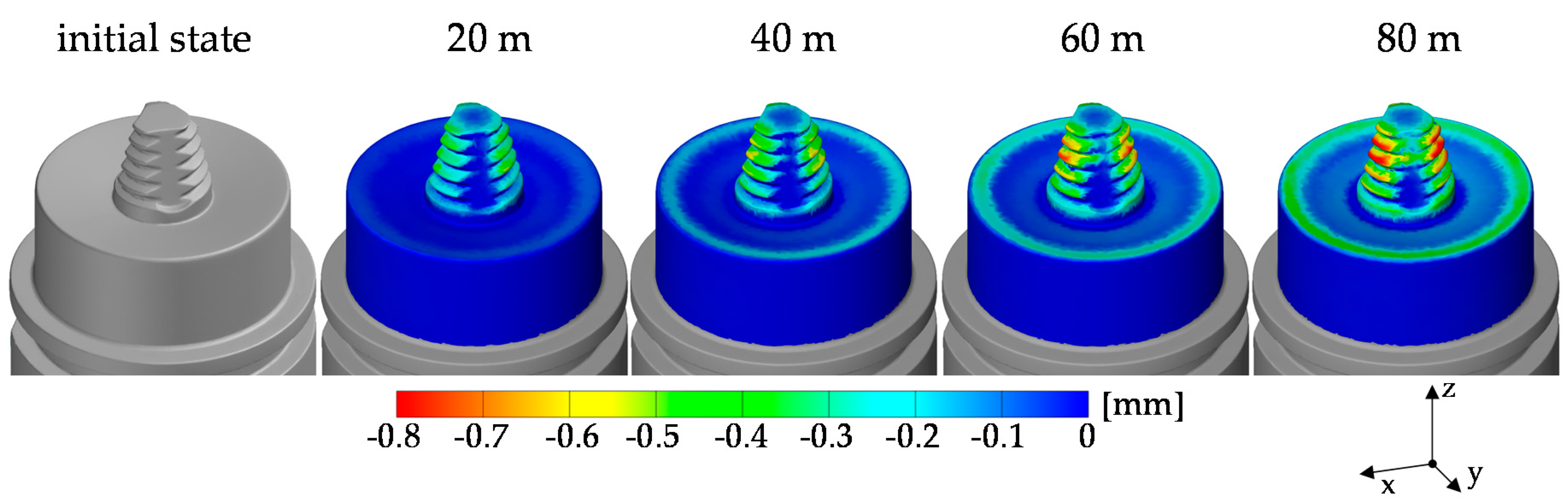
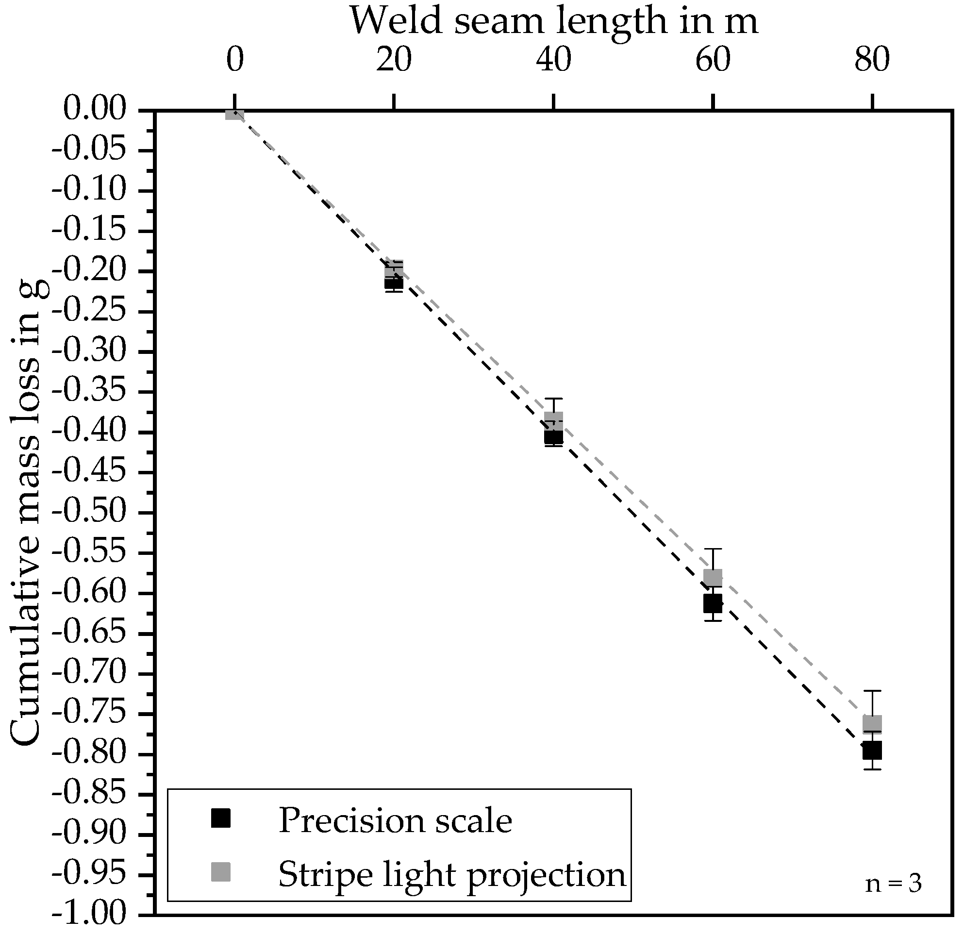
  • It was shown that the geometrical and weight related deviations induced, by FSW tool wear, could be determined using stripe light projection. With this approach it was possible to illustrate and describe the FSW tool wear three-dimensionally as a function of the weld seam length for geometric elements on the tool such as shoulder, thread, or flanks. Therefore, significant areas of tool wear could be analyzed three-dimensionally and non-destructively in order to determine geometric deviations.
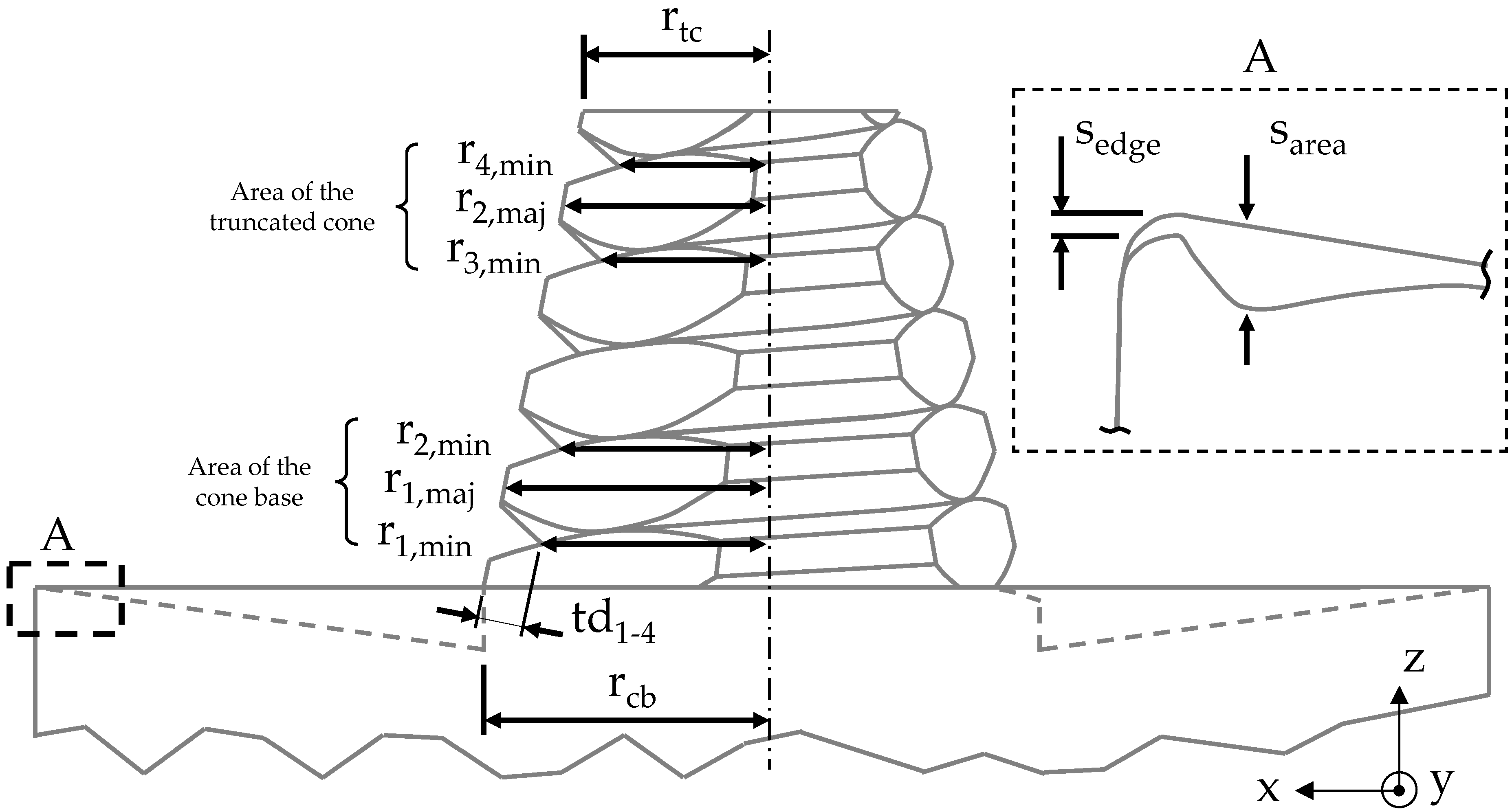
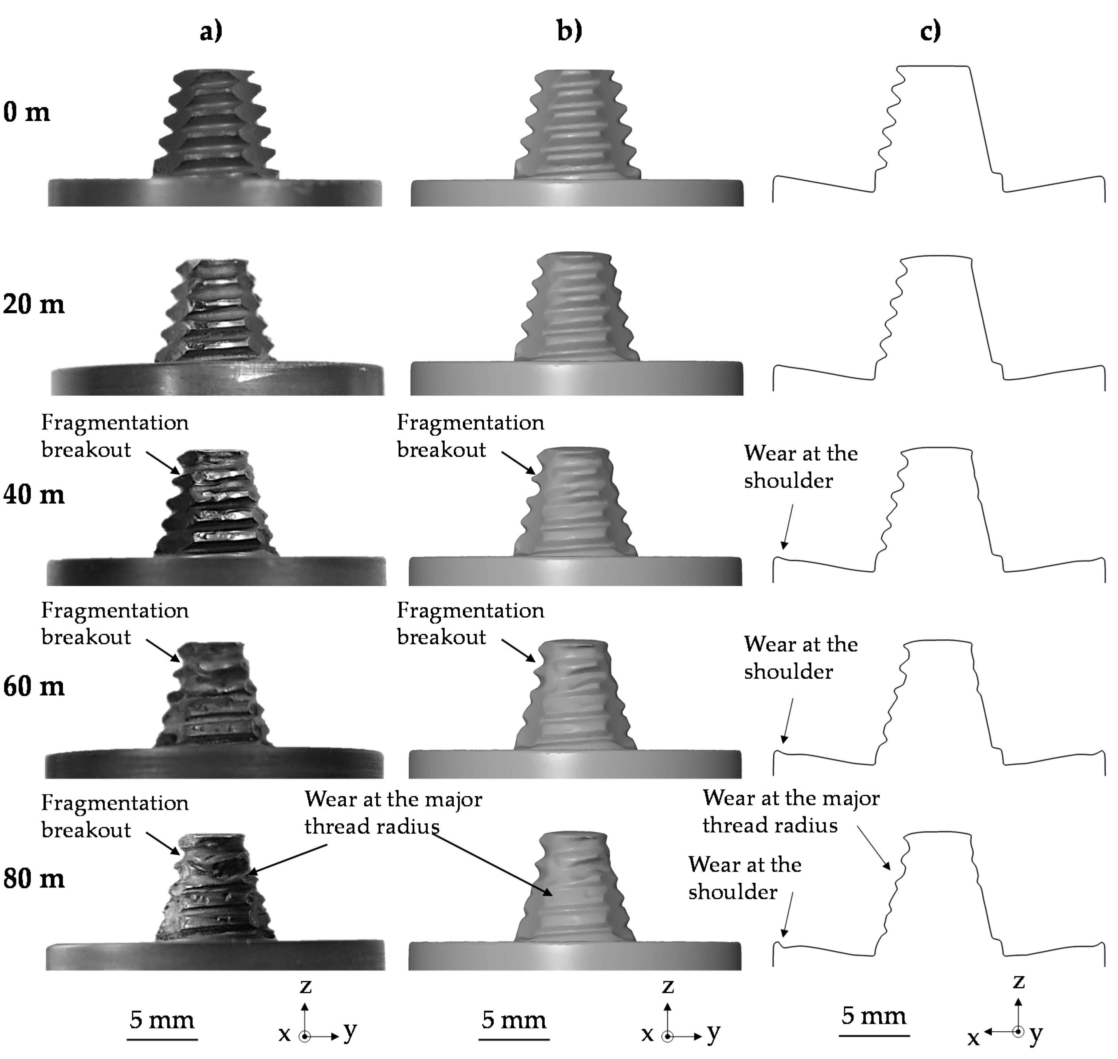
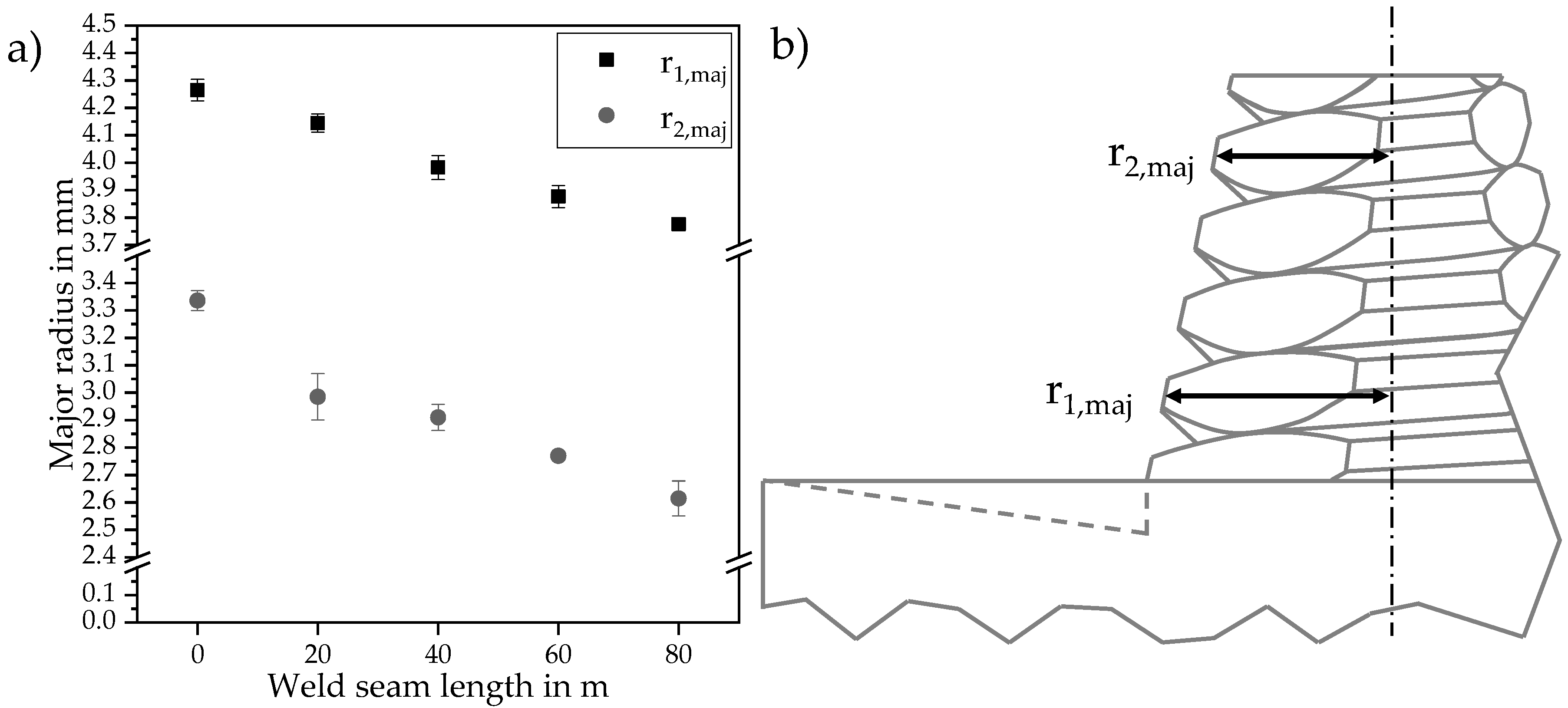
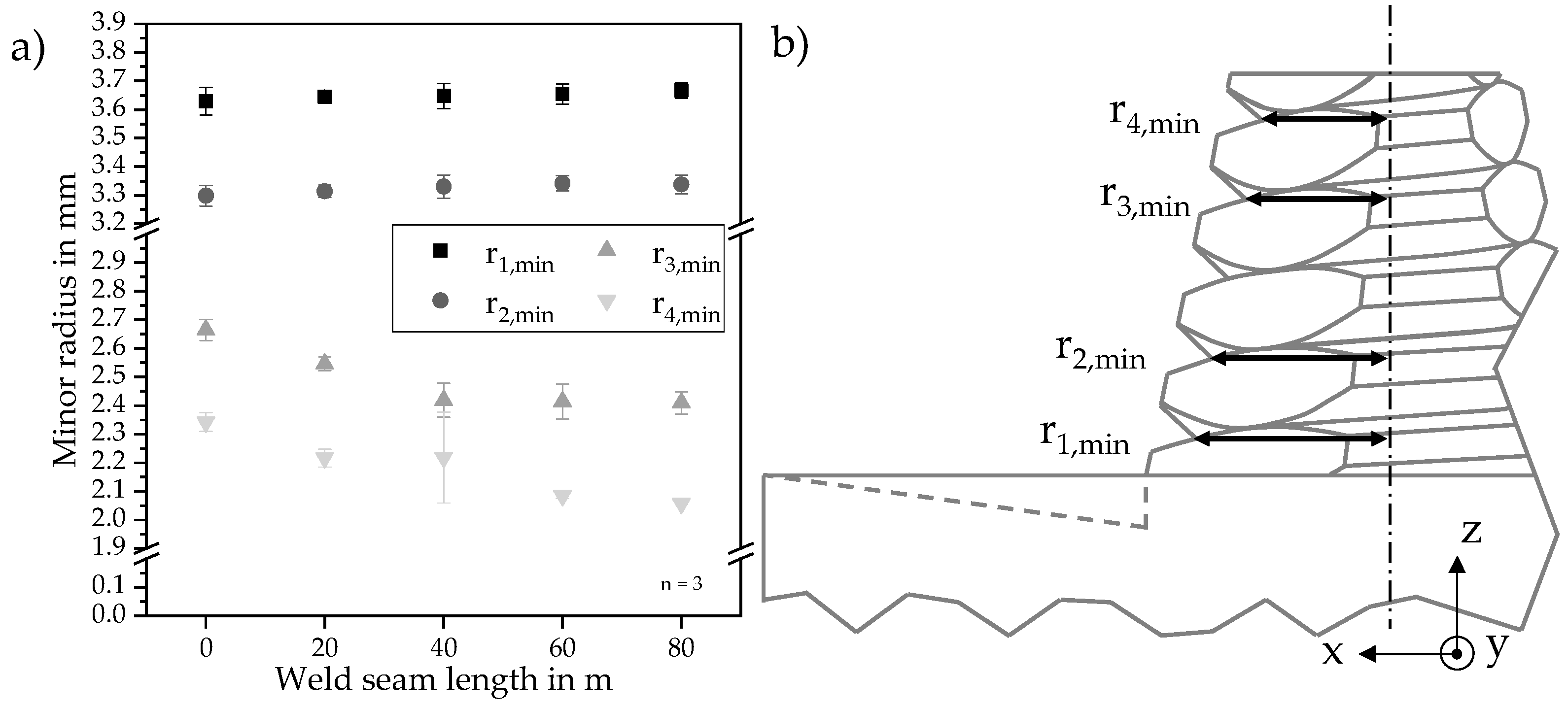
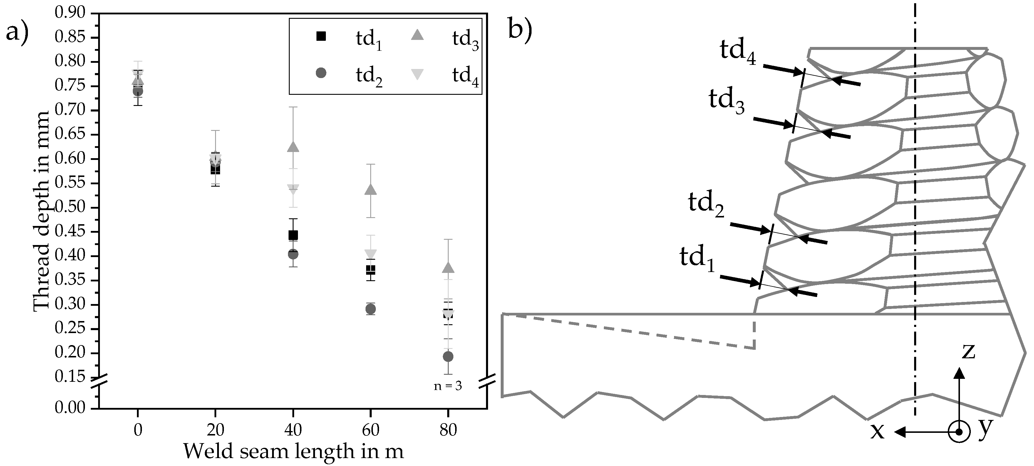
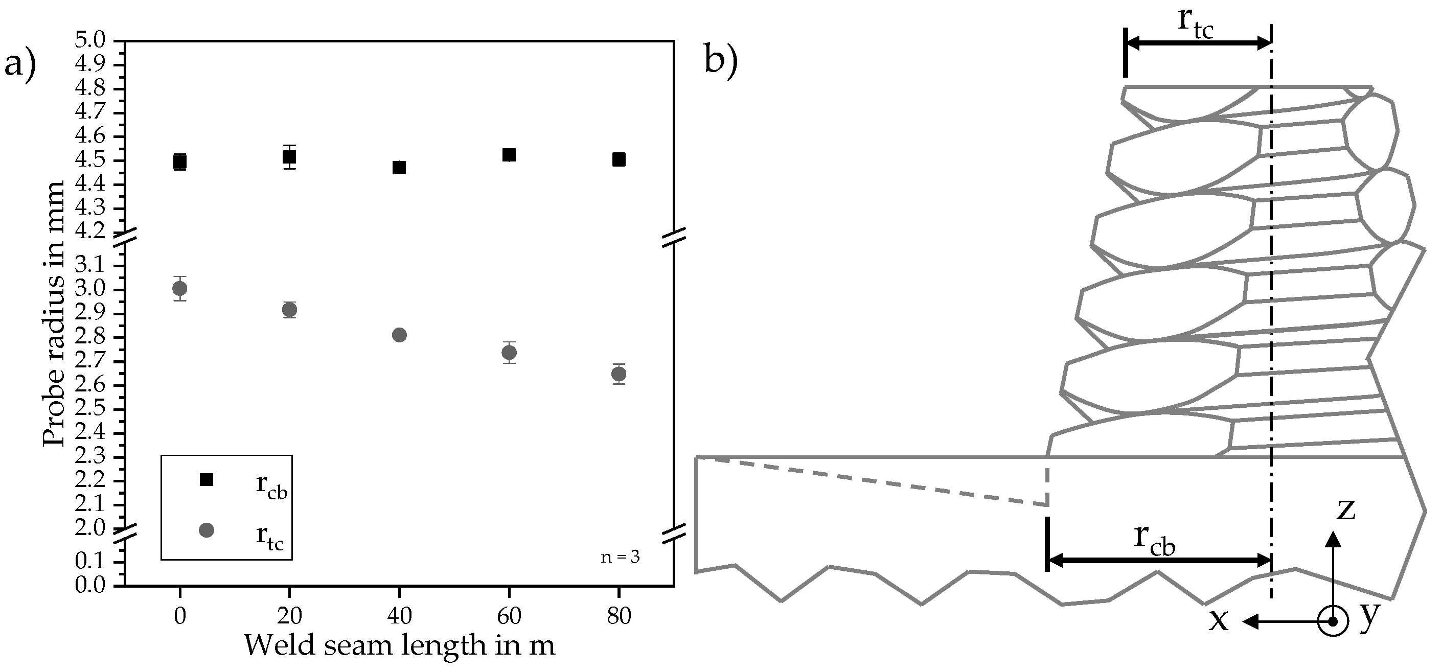
  • Within the geometrical characterization of FSW tools a varying amount of wear was identified along the tapered probe surface. Compared to the cone base of the probe, significant wear was measured in the area of the truncated cone. The geometric deviation due to wear showed a reduction of the thread depth of up to 74% compared to the initial state, which resulted from a higher wear at the major thread radius to the minor thread radius.
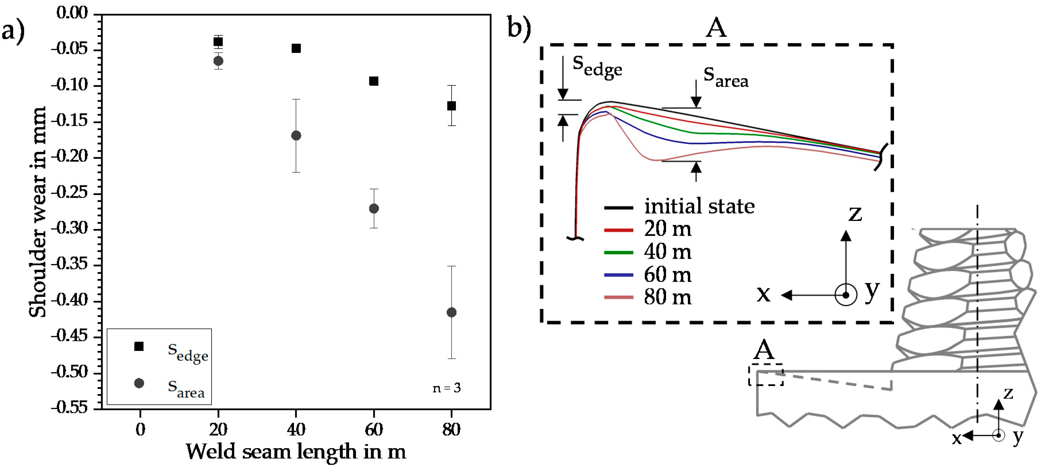
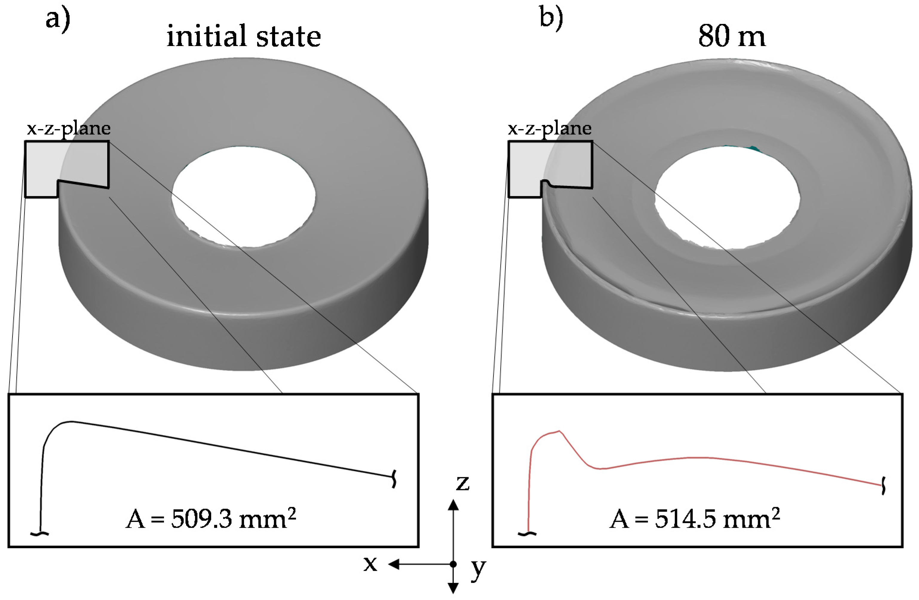
  • At the shoulder edge and the shoulder surface area a non-linear and progressive geometrical deviation was observed. The three-dimensional wear analysis showed that this behavior occurred after a weld seam length of 40 m for the first time and with further increase of 20 m weld seam length the shoulder surface wear is not only visible on the outer diameter area, but almost on the complete shoulder surface.
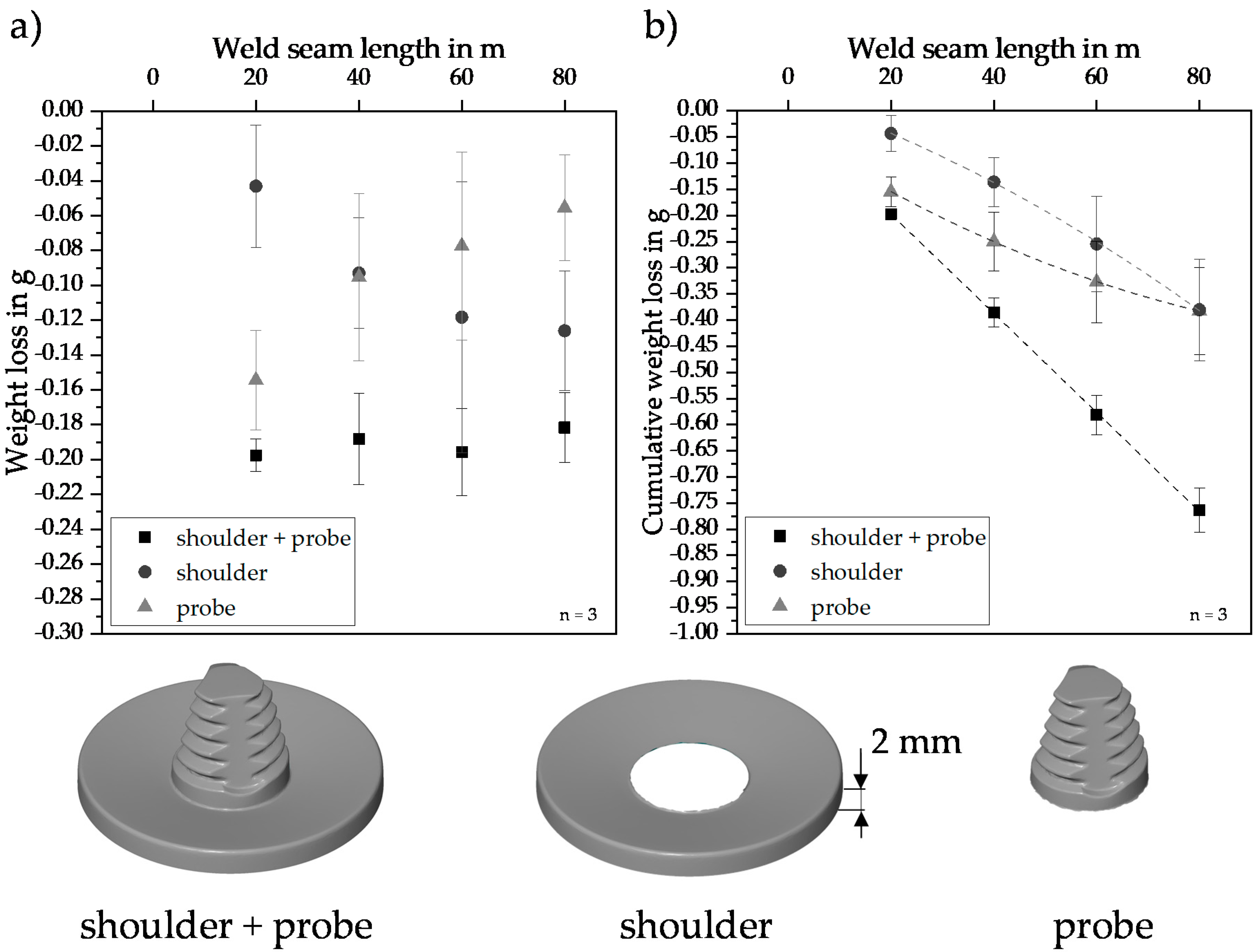
  • The weight loss due to wear was characterized separately without weighing the tool. This allowed a separate analysis of wear for the shoulder and probe. For the probe, a degressive wear behavior was determined at a total weld seam length of 80 m, resulting in a weight change of 14.4% to the initial state. The shoulder showed a progressive behavior due to the continuously increasing friction surface. Compared to the initial state a weight change of 2.7% was observed.
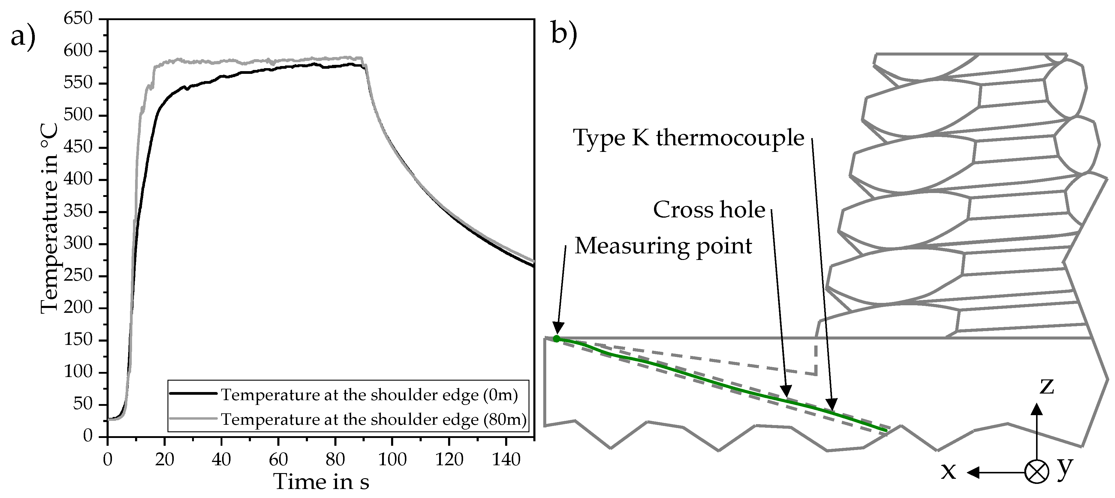
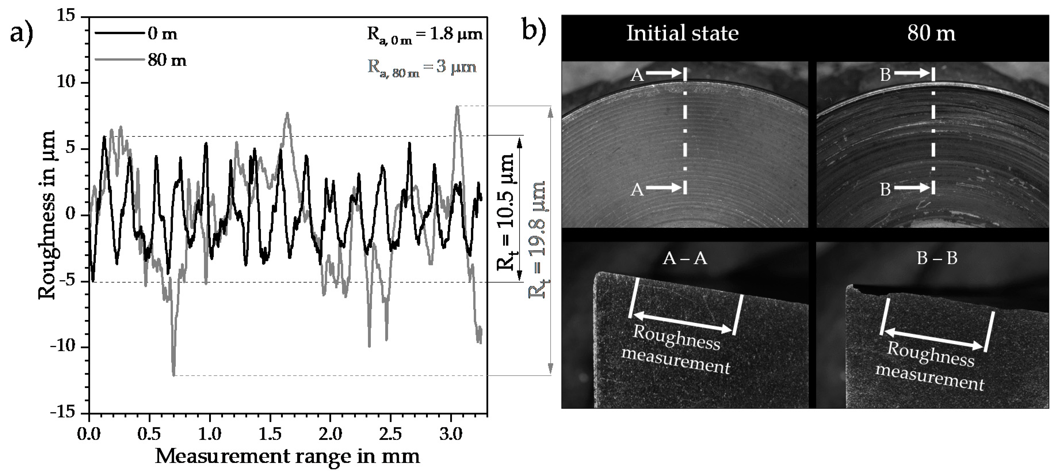
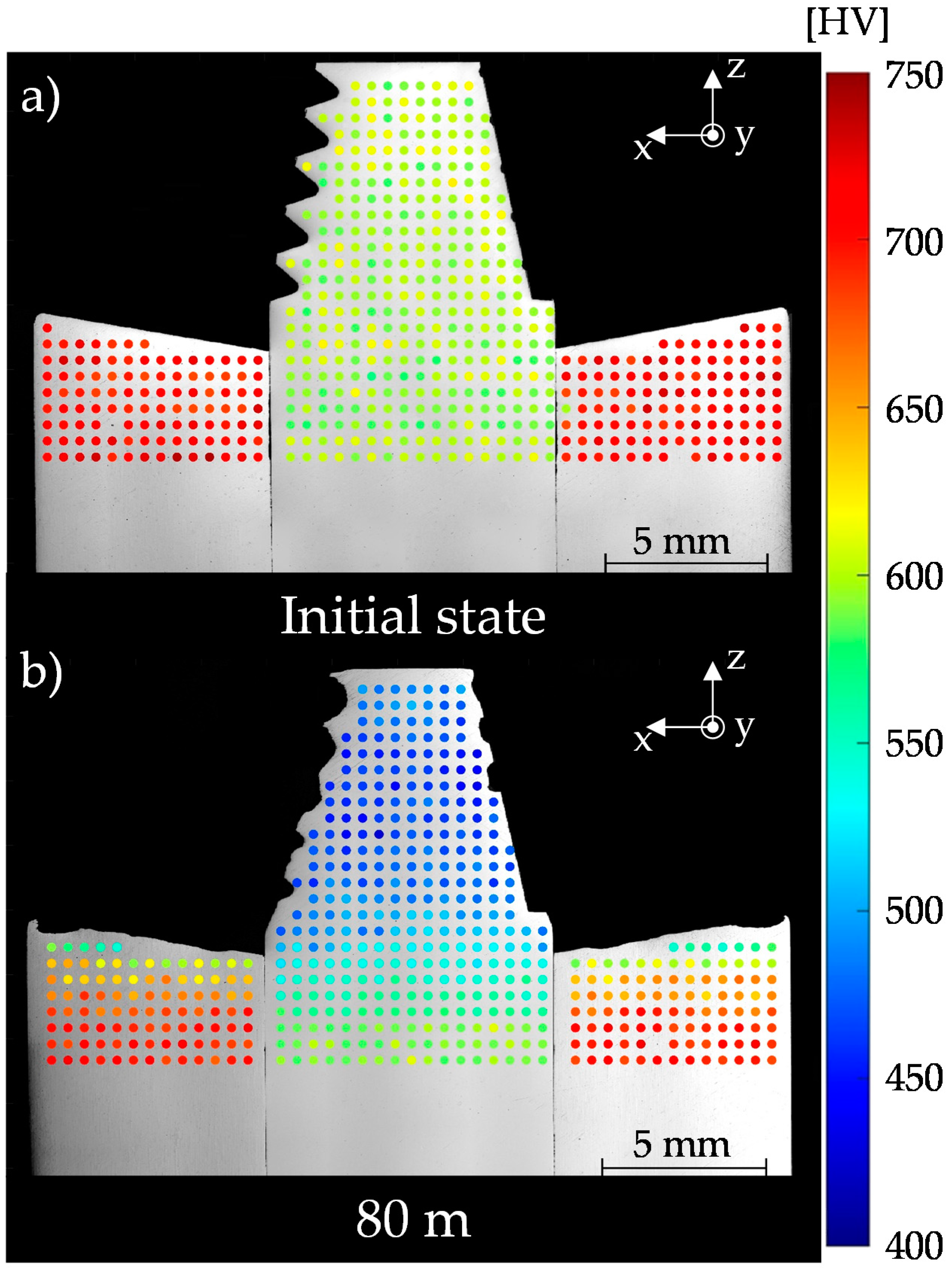
  • A weld seam length of up to 80 m exhibits an increased joining temperature due to a growth of the surface roughness. Furthermore, the joining temperature of up to 559.8 °C caused a hardness reduction of shoulder and probe which additionally favored the tool wear.
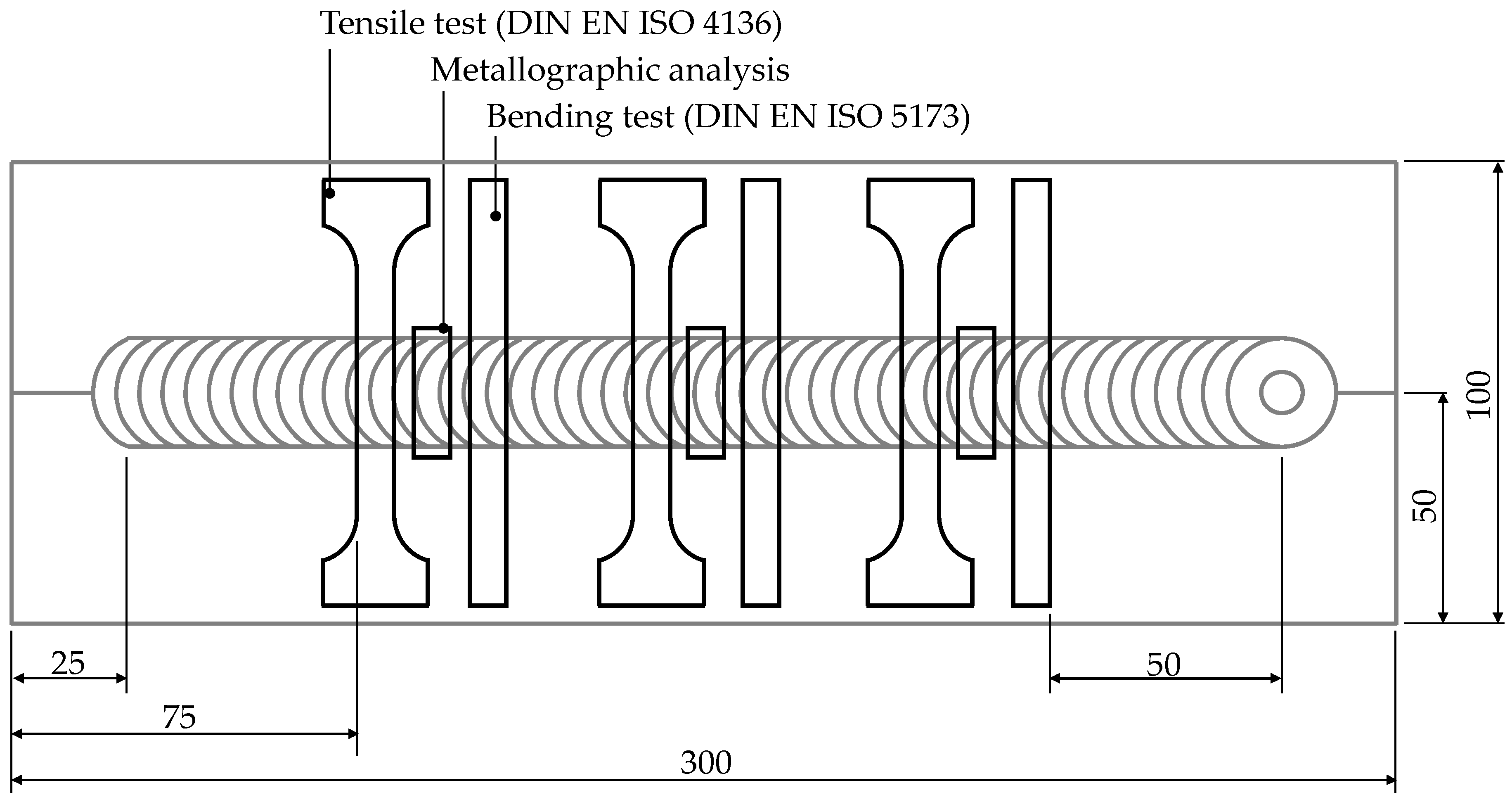
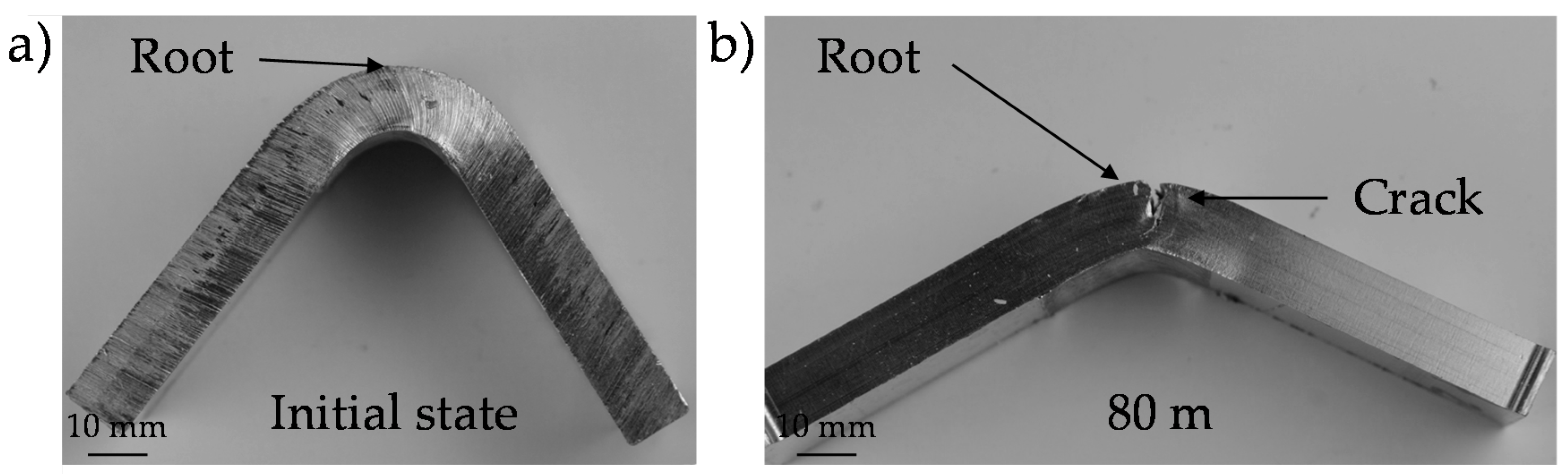
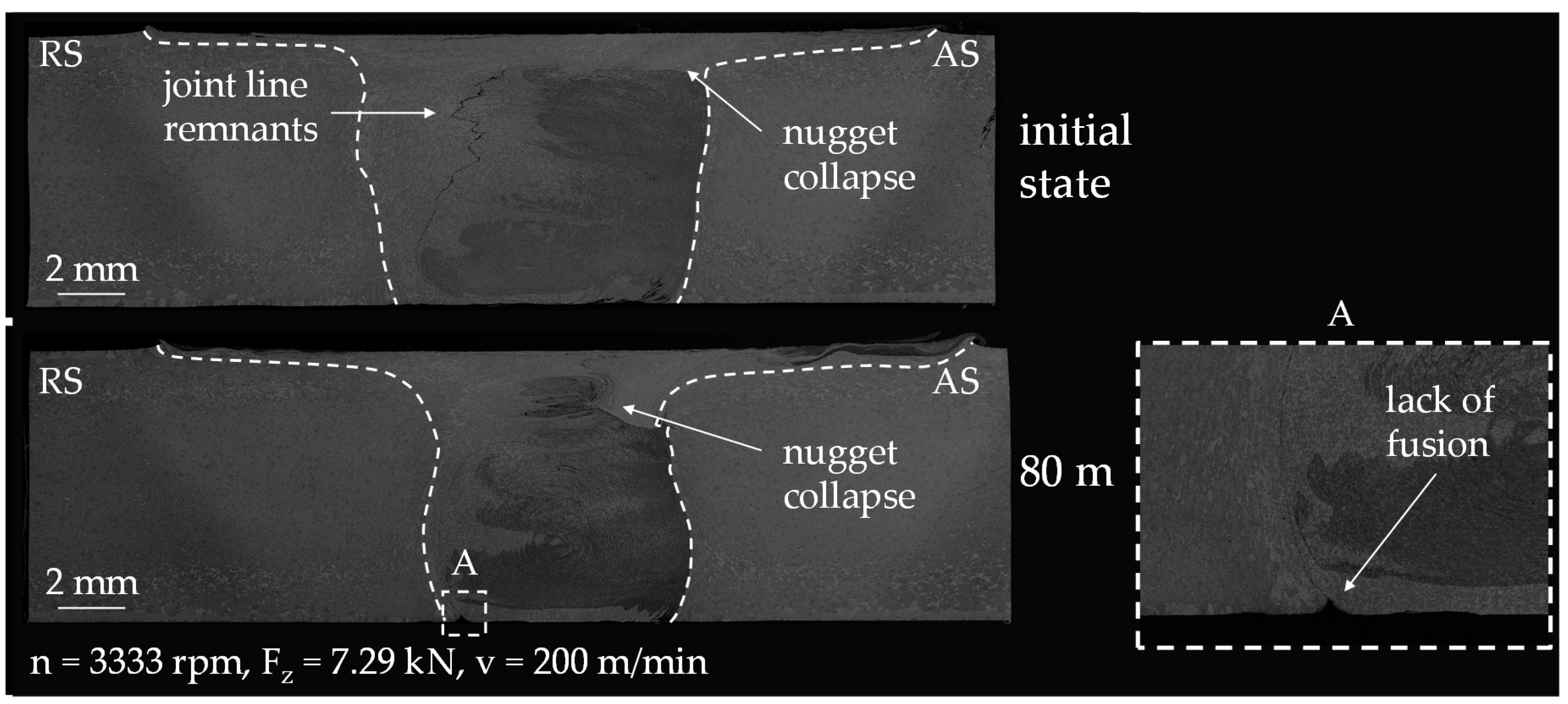
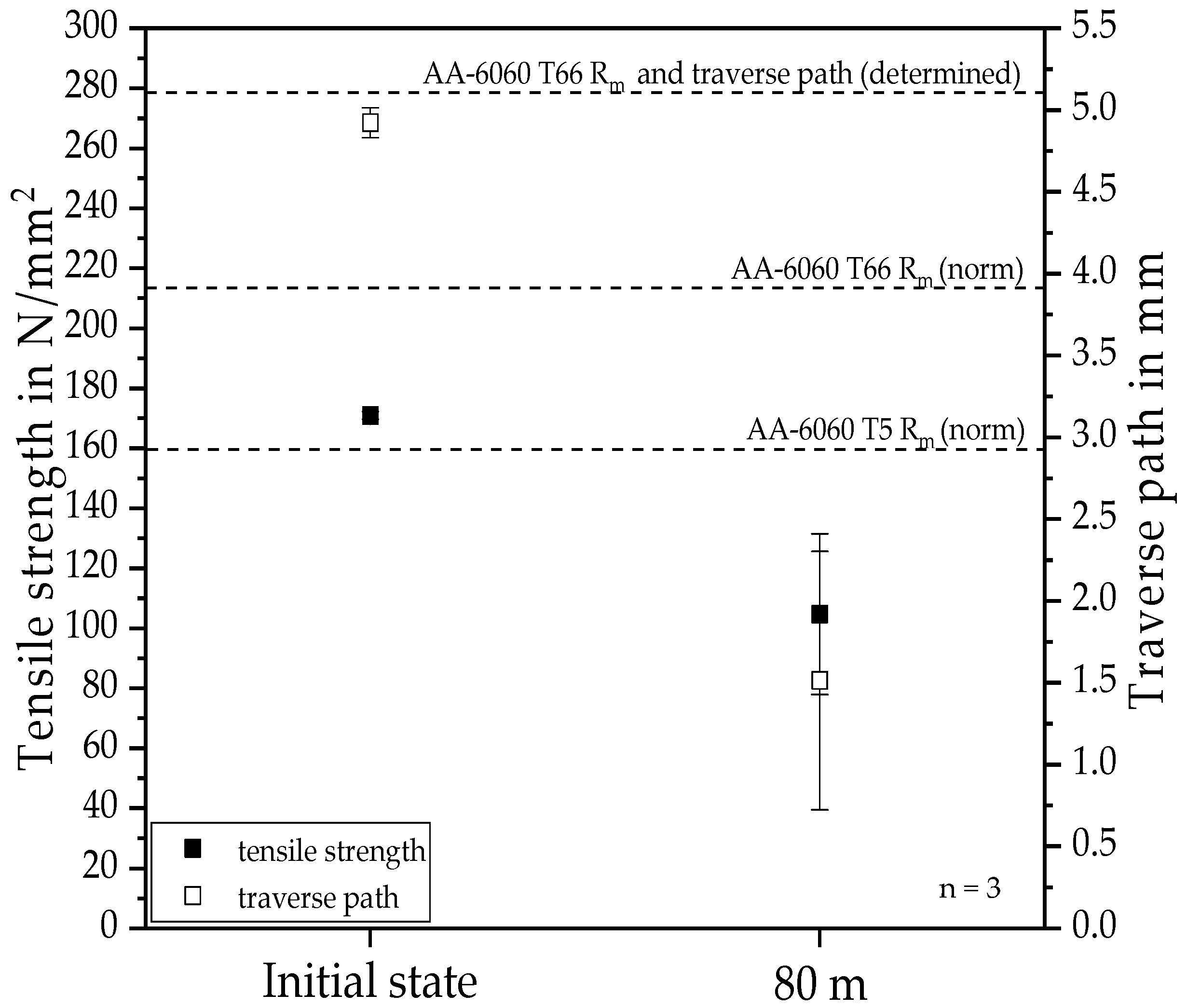
  • Surface properties and tensile strength are negatively affected by increased tool wear and thus adjustments of the process managements are necessary to prevent weld seam irregularities such as insufficient penetration.

Author Contributions

Methodology, M.H.; investigation, M.H.; writing—original draft preparation, M.H.; writing—review and editing, M.H., M.G. and J.P.B.; supervision, J.P.B. All authors have read and agreed to the published version of the manuscript.

Funding

This research received no external funding.

Acknowledgments

All the Authors would like to thank Marcus Glaser and Finn Steegers for the provided software to create the hardness maps used in this study.

Conflicts of Interest

The authors declare no conflict of interest.

References

  1. Ostermann, F. Anwendungstechnologie Aluminium; Springer Vieweg: Berlin/Heidelberg, Germany, 2007. [Google Scholar]
  2. Karakizis, P.N.; Pantelis, D.I.; Dragatogiannis, D.A.; Bougiouri, V.D.; Charitidis, C.A. Study of friction stir butt welding between thin plates of AA5754 and mild steel for automotive applications. Int. J. Adv. Manuf. Technol. 2019, 102, 3065–3076. [Google Scholar] [CrossRef]
  3. Richter, B. Robot-based Friction Stir Welding for E-mobility and General Applications. Biul. Inst. Spaw. Gliwicach 2017, 61, 103–110. [Google Scholar] [CrossRef] [Green Version]
  4. Goyal, A.; Garg, R.K. Parametric optimization of friction stir welding process for marine grade aluminum alloy. Int. J. Struct. Integr. 2019, 10, 162–175. [Google Scholar] [CrossRef]
  5. Reddy, S.N.J.; Sathiskumar, R.; Kumar, K.G.; Jerome, S.; Jebaraj, A.V.; Arivazhagan, N.; Manikandan, M. Friction based joining process for high strength aerospace Aluminum alloy. Mater. Res. Express 2019, 6, 0865a3. [Google Scholar] [CrossRef]
  6. Ruhstorfer, M. Rührreibschweißen von Rohren. Ph.D. Thesis, Technical University of Munich, Munich, Germany, 2012. (In German). [Google Scholar]
  7. Schmid, D. Rührreibschweißen von Aluminiumlegierungen mit Stählen für die Automobilindustrie. Ph.D. Thesis, Technical University of Munich, Munich, Germany, 2015. (In German). [Google Scholar]
  8. Zum Gahr, K.H. Tribologie: Reibung-Verschleiß Schmierung. Naturwissenschaften 1985, 72, 260–267. [Google Scholar] [CrossRef] [PubMed]
  9. Czichos, H.; Habig, K.H. Tribologie-Handbuch: Tribometrie, Tribomaterialien, Tribotechnik, 4th ed.; Springer Vieweg: Wiesbaden, Germany, 2010. [Google Scholar]
  10. Thompson, B.T. Tool Degradation Characterization in the Friction Stir Welding of Hard Metals, Graduate Program in Welding Engineering; The Ohio State University: Columbus, OH, USA, 2010. [Google Scholar]
  11. Hoßfeld, M. Experimentelle, Analytische und Numerische Untersuchungen des Rührreibschweißprozesses. Ph.D. Thesis, University of Stuttgart, Stuttgart, Germany, 2016. (In German). [Google Scholar]
  12. Prado, R.A.; Murr, L.E.; Soto, K.F.; McClure, J.C. Self-optimization in tool wear for friction-stir welding of Al 6061+ 20% Al2O3 MMC. Mater. Sci. Eng. 2003, 349, 156–165. [Google Scholar] [CrossRef]
  13. Weinberger, T.; Khosa, S.U.; Führer, B.; Enzinger, N. Analysis of tool wear and failure mechanism during friction stir welding of steel. In Proceedings of the 7th International Symposium Friction Stir Welding, Awaji, Japan, 20–22 May 2008. [Google Scholar]
  14. Kalashnikov, K.N.; Zhukov, L.L.; Kalashnikova, T.A. Influence of tribological inter-action conditions on the material transfer process during adhesive friction between Al-alloy and high-speed tool steel. In AIP Conference Proceedings; AIP Publishing LLC: Melville, NY, USA, 2019. [Google Scholar]
  15. Sommer, K.; Heinz, R.; Schöfer, J. Verschleiß Metallischer Werkstoffe; Vieweg und Teubner: Wiesbaden, Germany, 2010. (In German) [Google Scholar]
  16. Eff, M. The Effects of Tool Texture on Tool Wear in Friction Stir Welding of X-70 Steel. Ph.D. Thesis, The Ohio State University: Columbus, OH, USA, 2012. [Google Scholar]
  17. Park, S.H.C.; Sato, Y.S.; Kokawa, H.; Okamoto, K.; Hirano, S.; Inagaki, M. Boride formation induced by pcBN tool wear in friction-stir-welded stainless steels. Metall. Mater. Trans. A 2009, 40, 625–636. [Google Scholar] [CrossRef]
  18. Tarasov, S.Y.; Rubtsov, V.E.; Kolubaev, E.A. A proposed diffusion-controlled wear mechanism of alloy steel friction stir welding (FSW) tools used on an aluminum alloy. Wear 2014, 318, 130–134. [Google Scholar] [CrossRef]
  19. Prado, R.A. Friction Stir Welding: A Study of Tool Wear Variation in Aluminum Alloy 6061+ 20% Al2O3. Frict. Stir Weld. Process. 2001, 2001, 105–116. [Google Scholar]
  20. Shindo, D.J.; Rivera, A.R.; Murr, L.E. Shape optimization for tool wear in the friction-stir welding of cast AI359-20% SiC MMC. J. Mater. Sci. 2002, 37, 4999–5005. [Google Scholar] [CrossRef]
  21. Fernandez, G.J.; Murr, L.E. Characterization of tool wear and weld optimization in the friction-stir welding of cast aluminum 359+ 20% SiC metal-matrix composite. Mater. Charact. 2004, 52, 65–75. [Google Scholar] [CrossRef]
  22. Liu, H.J.; Feng, J.C.; Fujii, H.; Nogi, K. Wear characteristics of a WC–Co tool in friction stir welding of AC4A+ 30 vol% SiCp composite. Int. J. Mach. Tools Manuf. 2005, 45, 1635–1639. [Google Scholar] [CrossRef]
  23. Prater, T.J.; Strauss, A.M.; Cook, G.E.; Gibson, B.T.; Cox, C.D. A phenomenological model for tool wear in friction stir welding of metal matrix composites. Metall. Mater. Trans. A 2013, 44, 3757–3764. [Google Scholar] [CrossRef]
  24. Sahlot, P.; Jha, K.; Dey, G.K.; Arora, A. Wear-induced changes in FSW tool pin profile: Effect of process parameters. Metall. Mater. Trans. A 2018, 49, 2139–2150. [Google Scholar] [CrossRef]
  25. Więckowski, W.; Burek, R.; Lacki, P.; Łogin, W. Analysis of wear of tools made of 1.2344 steel and MP159 alloy in the process of friction stir welding (FSW) of 7075 T6 aluminum alloy sheet metal. Eksploatacja i Niezawodność 2019, 21, 54–59. [Google Scholar] [CrossRef]
  26. Schüddekopf, S.; Mienert, G.; Böhm, S. Effects on the Friction Stir Welding process by laser implanting ceramic particles into the boundary layer. In Proceedings of the 12th International Symposium on FSW (12IFSW), Chicoutimi, Canada, 26–28 June 2018. [Google Scholar]
  27. Schmidt, H.; Hattel, J.; Wert, J. An analytical model for the heat generation in friction stir welding. Model. Simul. Mater. Sci. Eng. 2003, 12, 143. [Google Scholar] [CrossRef]
  28. Adesina, A.Y.; Al-Badour, F.A.; Gasem, Z.M. Wear resistance performance of AlCrN and TiAlN coated H13 tools during friction stir welding of A2124/SiC composite. J. Manuf. Process. 2018, 33, 111–125. [Google Scholar] [CrossRef]
  29. Roberts, G.A.; Kennedy, R.; Krauss, G. Tool Steels; ASM international: Novelty, OH, USA, 1998. [Google Scholar]
Figure 1. Dimensions of the tool.
Jmmp 04 00060 g001
Figure 2. Measuring system with the optical scanner GOM ATOS Core 300.
Jmmp 04 00060 g002
Figure 3. Measuring plane on the friction stir welding (FSW) tool.
Jmmp 04 00060 g003
Figure 4. Measuring design with the definition of points measured on the tool.
Jmmp 04 00060 g004
Figure 5. Position of the specimens and their prescribed position.
Jmmp 04 00060 g005
Figure 6. Qualitative inspection of the FSW tools by photographic images (a), stripe light projection (b), and stripe light projection in the full section view (c).
Jmmp 04 00060 g006
Figure 7. Wear deviation of the major thread radius as a function of the weld seam length in (a) measured with stripe light projection and (b) at the measuring points.
Jmmp 04 00060 g007
Figure 8. Wear deviation of the minor thread radius as a function of the weld seam length in (a) measured with stripe light projection and (b) at the measuring points.
Jmmp 04 00060 g008
Figure 9. Wear behavior of the thread depth as a function of the weld seam length in (a) measured with the stripe light projection and (b) at the measuring points.
Jmmp 04 00060 g009
Figure 10. Wear behavior of the probe radii as a function of the weld seam length in (a) measured with the stripe light projection and (b) at the measuring points.
Jmmp 04 00060 g010
Figure 11. Wear behavior of the shoulder as a function of the weld seam length in (a) at the detailed view of the associated measuring points in (b).
Jmmp 04 00060 g011
Figure 12. 3D surface measurement of the tools as a function of the weld seam length.
Jmmp 04 00060 g012
Figure 13. Cumulative weight loss in dependence of the weld seam length.
Jmmp 04 00060 g013
Figure 14. Distribution of weight loss due wear. Weight loss after every 20 m of weld seam length in (a) and cumulative with respect to the initial state in (b).
Jmmp 04 00060 g014
Figure 15. Analysis of the effective shoulder area in the initial state (a) and after 80 m weld length in (b).
Jmmp 04 00060 g015
Figure 16. (a) Temperature measurements for 0 and 80 m weld seam length and (b) position of the shoulder integrated thermocouple.
Jmmp 04 00060 g016
Figure 17. Surface roughness in (a) at the respective measuring lines in (b).
Jmmp 04 00060 g017
Figure 18. Hardness mapping in the cross section of the tool in the initial state in (a) and after a weld seam length of 80 m in (b).
Jmmp 04 00060 g018
Figure 19. Visual inspection of the performed welds with the tool in the initial state (a) and with the tool after a weld seam length of 80 m in (b).
Jmmp 04 00060 g019
Figure 20. Root-side bending test with the tool in the initial state (a) and with the tool after a weld seam length of 80 m in (b).
Jmmp 04 00060 g020
Figure 21. Metallographic analysis.
Jmmp 04 00060 g021
Figure 22. Tensile strength and traverse path.
Jmmp 04 00060 g022
Table 1. Chemical composition of AA-6060.
ElementSiFeCuMnMgCrZnTiAl
Min. %0.30.1--0.35---Bal.
Max. %0.60.30.10.10.60.050.150.1

