An Experimental Investigation of Combined Symmetric-Asymmetric Composite Laminates


Department of Mechanical Engineering, Clemson University, Clemson, SC 29634, USA
*
Author to whom correspondence should be addressed.
†
Current address: Flour Daniel Engineering Innovation Building, 218 S Palmetto Blvd, Clemson, SC 29631, USA.
J. Compos. Sci. 2019, 3(3), 71; https://0-doi-org.brum.beds.ac.uk/10.3390/jcs3030071
Submission received: 11 April 2019
/
Revised: 10 June 2019
/
Accepted: 3 July 2019
/
Published: 10 July 2019
Abstract
:It has been found that certain asymmetric composite laminates exhibit bistability, where the composite laminate exhibits multiple stable static equilibrium states. If the bistable composite is actuated, it will snap to its secondary equilibrium state and then remain there without further actuation. This study investigates how the amount of symmetry in a combined symmetric asymmetric rectangular laminate under an imposed clamped edge boundary condition affects the bistability and the curvature of the laminate. Laminates with varying amounts of asymmetry were fabricated and then measured using a profilometer to capture the curvatures of the equilibrium shapes. The results showed that up to 20% symmetry can be introduced in the laminate without a substantial loss in snap through curvature, and that up to 83% symmetry can be introduced in the laminate before bistability is lost. Finite element simulations were conducted in Abaqus and showed good correlation with the experimental results.
1. Introduction
The first major research into the behavior of bistable composites was done in 1981 by Michael W. Hyer [1]. Hyer experimentally investigated the phenomenon of asymmetric composite laminates and how their cured shapes diverged from the predictions of classical lamination theory. The principal phenomena behind the bistability lies in the thermal expansion coefficients of the fibers. The thermal expansion coefficient in the fiber direction is less than the thermal expansion coefficient perpendicular to the fibers. When an asymmetric laminate is made, there then exists a mis-match in the thermal expansion coefficients about the mid plane of the laminate. An asymmetric laminate will exhibit different types of curvature post cure due to residual stresses induced by dissimilar thermal expansion coefficients.
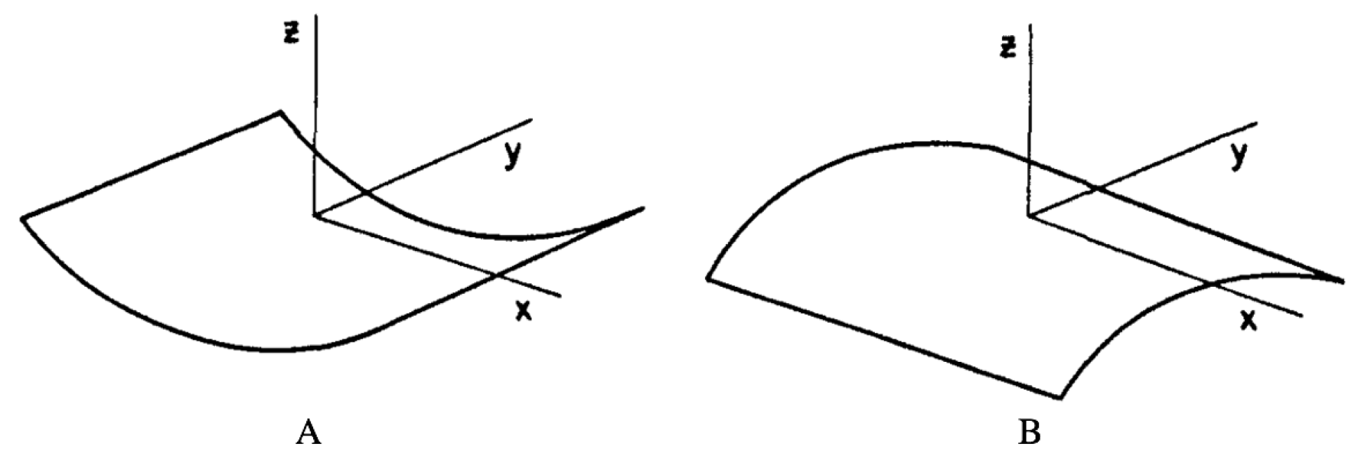
The cured shapes of the asymmetric laminates were seen as undesirable due to their inherent extension-bending coupling; Hyer sought to motivate further research on possible advantages and uses of these shapes. He showed that the principle curvature directions of the cylindrical bistable shapes are predictable and that thicker asymmetric laminates conformed to classical lamination theory. In particular, he observed that a 150 mm × 150 mm (5.91 in. × 5.91 in.) [02/902]T laminate exhibited snap-through behavior with two room temperature cylindrical shapes of opposite sign and perpendicular axes of curvature, as shown below in Figure 1.
Hyer went on to investigate the reasons why certain thin asymmetric laminates do not conform to classical lamination theory [2]. According to classical lamination theory, all asymmetric laminates are predicted to be saddle shape at room temperature [3]. Hyer investigated [02/902]T and [04/904]T square graphite-epoxy laminates and found that depending on the thickness of the laminate and the length of the side of the square the laminates were not saddle shaped but cylindrical with bistable behavior. Hyer attributed the cured shapes of the thin asymmetric laminates to geometric nonlinearities known as Flöppl–von Karman geometric nonlinearities, which are partial differential equations that describe the deflection of thin flat plates. Because of the geometric non linearities, Hyer developed an analytical solution using the Rayleigh–Ritz energy method as an extension of classical lamination theory which minimized the potential energy of the laminate, including the effects of thermal expansion. The solution allowed him to make bifurcation diagrams for both [02/902]T and [04/904]T square graphite-epoxy laminates and showed that, at a critical side length, the laminates became bistable. Before this critical length, he showed that the laminates are saddle shaped as would be predicted by classical lamination theory. He also postulated that the effects of moisture absorption, viscoelastic relaxation, and any mechanism that changes the internal stress state of the laminate are important for laminates near the critical length [2]. In addition, he postulated that asymmetric curing, asymmetric cooling, and asymmetric moisture absorption could result in the laminate favoring one of the bistable configurations and cause the snap through force to be greater going one direction compared to the force required to snap back to the other. Hyer continued his investigation by revising his previous theory. He computed numerical results for the in-plane residual strains of thin asymmetric laminates that cooled from curing into cylindrical shapes at room temperature [4].
Research was then done to investigate the temperature–curvature relationship for asymmetric cross-ply laminates. Composite laminates are typically cured at elevated temperatures in a mold under vacuum, either in an autoclave or simple curing oven. Typically, they are allowed to cool in the mold remaining under vacuum such that they do not deform while cooling. Hyer and Hamamoto reheated cured samples, allowing them to deform, and measured the curvature along a range of temperature and they developed a temperature–curvature relationship for asymmetric laminates [5].
After much research was done beginning with Hyer et al., and continuing with many other researchers, the room temperature shapes of asymmetric laminates can be well predicted based on ply orientation and thickness [6,7,8]. Jun et al. showed that residual thermally induced in-plane shear strains are not insignificant for medium width-to-thickness ratio laminates that are bistable [6]. They also investigated the effects of width-to-thickness, number of layers, and stacking sequences for asymmetric cross ply laminates. Ren et al. continued with the developed Rayleigh–Ritz energy method and showed that the cured shape of a cross-ply laminate depends on stacking sequence, radius, thickness, and size [7]. They developed a model to predict the cured shape based on these parameters and compared the results to FEA predictions as well as experimental results, and found good correlations. Thus, they developed a model to give guidance to the manufacture of asymmetric cross-ply laminates. With cross-ply laminates thus being well characterized, Jun et al. sought to characterize asymmetric laminates with arbitrary lay-up angles [8]. They present a formulation that predicts the curvatures and principle directions of curvature for asymmetrically laminated composites that are not cross-ply. They found that their formulation agreed well with classical lamination theory for the range of length-to-thickness ratios that they studied.
With the post-cure shape of asymmetric laminates as well as their response to thermal loading being well characterized, attention thus was turned towards improved modeling and application of bistable composites. Schlecht et al. built on Hyer’s previous work and used FEA to predict the snap through force as well as stresses and strains of asymmetric bistable laminates [9]. Betts et al. developed a novel method of mapping the surface profiles of asymmetric laminates [10]. They found that existing modeling techniques are quite good at predicting room temperature shapes but are also quite sensitive to imperfections. They emphasized the continued need for accurate modeling as the design of mechanisms using the behavior of bistable composites increases. Thus, Giddings et al. sought to include imperfections in the prediction of cured laminate shapes using ANSYS FEA software (version 18, ANSYS, Inc., Canonsburg, PA, USA) [11]. They included manufacturing imperfections such as high resin areas and ply-thickness variations in their model. They achieved this by analyzing composite laminates using optical microscopy and measuring cured shapes using a Peak Motus motion analysis system. They were able to accurately predict the two equilibrium states of an imperfect laminate to within 3–7% compared to errors of 7–73% of an idealized laminate by including the previously mentioned manufacturing imperfections, such as high resin areas and ply-thickness variations. Their model also included the prediction of bistable laminate deflection under thermal loading within a temperature range of 20–110 °C. The work of Giddings et al. on characterizing the shape of laminates over a given temperature range was developed from the work of Dano et al. who developed a model to predict the out of plane displacements of flat asymmetric composite laminates as they cool from the elevated curing temperature [12]. Tawfik et al. developed an FEA model using ABAQUS to predict the shapes of asymmetric cross-ply laminates under thermal curing stresses and to investigate the instability point of snap-through [13]. They investigated rectangular asymmetric cross-ply laminates and investigated how the aspect (length vs. width) ratio affects bistability.
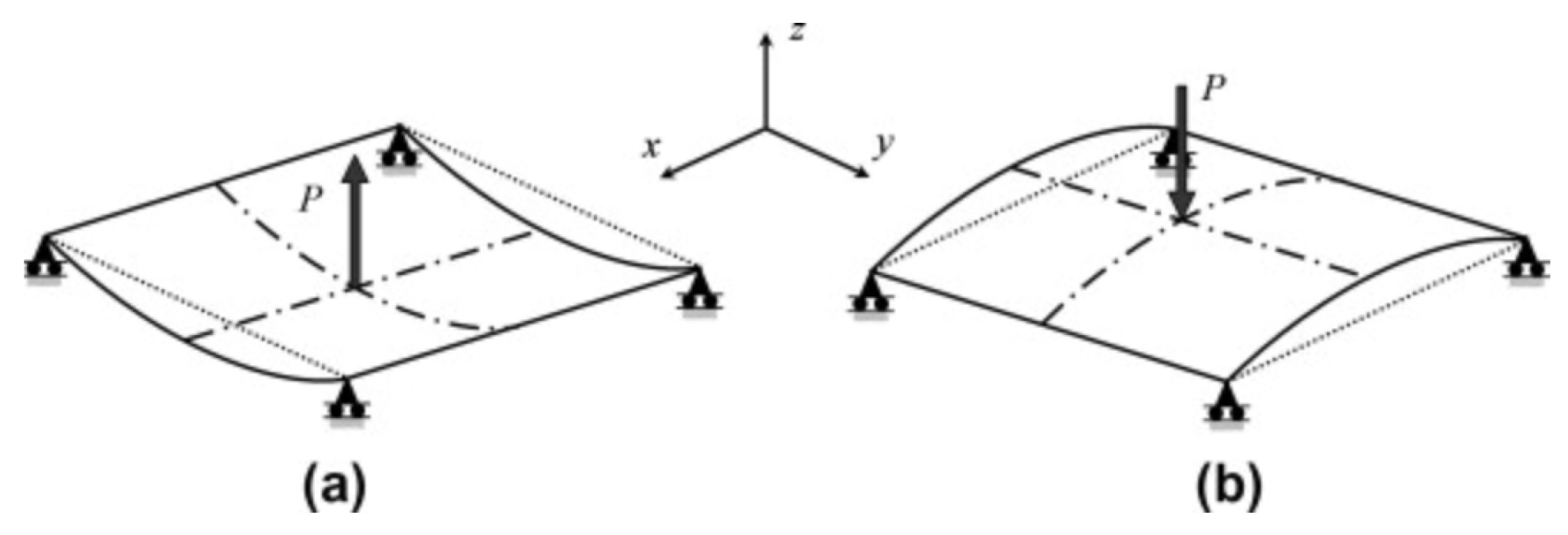
With regard to exterior boundary conditions on bistable laminates, various conditions have been used in research in characterizing bistable composite laminates thus far. The boundary conditions that have been typically applied in the research that has been conducted have included some variation of the conditions shown in Figure 2, where the four points of the corners are fixed in z and allowed to move in x and y such that they can “float”, and a force is applied at the center to snap the laminate through to the other position.
Tawfik et al. used an air table to experimentally recreate these boundary conditions [14]. Wang et al. used a three point bending test to measure the snap through forces of symmetric bistable composite laminates (VPPMCS) [15]. Dano et al. fixed square laminates in the center and then used two protruding supports applied moments to snap the laminates through from one position to the other [16]. While floating boundary conditions allow for simple characterization of the bistability of the laminates, they are not helpful in moving towards practical functional applications of bistable composites, whereby some amount of fixed boundary conditions are necessary. With regard to the boundary conditions between symmetric and asymmetric portions within a bistable laminate, some research has been done so far. Mattioni et al. studied the effects of varying the layup pattern but only considered a laminate that was half symmetric and half asymmetric. They studied a 180 mm × 360 mm 8 ply laminate where the left hand 180 mm × 180 mm section had a layup of [02,902]S and the right hand 180 mm × 180 mm section had a layup of [04,904]T. Mattioni et al. also did a parametric study to investigate the effects of boundary conditions. The parameters they studied were the thickness and stacking sequence of the symmetric part with the symmetric portion fixed at the short edge. The asymmetric portion was left unchanged. They compared the results to the original laminate both unrestrained and with the symmetric portion fixed. They found that fixing one edge eliminates the post cure curvature at that edge, but that, at the free edge, up to 60% of the curvature of the unrestrained laminate is retained. They also found that, for every configuration of the symmetric portion, the longitudinal or snap through curvature was 99% of the unrestrained panel. Thus, they found that snap through curvature of the asymmetric portion remained virtually unchanged, despite changes in the symmetric portion. They did not, however, change the overall size of either the symmetric or asymmetric portion.
The goal of this study is to gain more understanding on how introducing a symmetric region between a clamped edge boundary condition and an asymmetric region affects the bistability and curvature of a combined symmetric asymmetric laminate. The motivation behind introducing symmetry is that it creates a transition between the curved edge of a purely asymmetric laminate and the straight edge of a purely symmetric laminate, allowing for better implementation of the fixed edge boundary condition. The reason why creating a transition between curved and straight is critical is because a pure asymmetric laminate exhibiting bistability can lose bistability when one edge is fixed, depending on its overall geometry, and, if two opposing edges are fixed, no bistability will be exhibited as the edges cannot be deflected. Thus, having a transition zone allows for fixed external boundary conditions to be imposed on a bistable laminate while mitigating the effect of the boundary conditions on the snap through behavior. The ability to apply fixed external boundary conditions on bistable laminates that allow for the retaining of the bistability is critical for the implementation of bistable laminates in the realm of morphing and adaptive structures. Little research has been done to gain a better understanding on how external boundary conditions affect the bistability of bistable composite laminates. This study seeks to investigate how tailoring the laminate structure through the use of a symmetric region between a clamped edge boundary condition and an asymmetric region can perhaps reduce the negative effects of implementing a fixed edge boundary condition on a purely asymmetric bistable laminate.
2. Experimental Setup
2.1. Design of Experiment
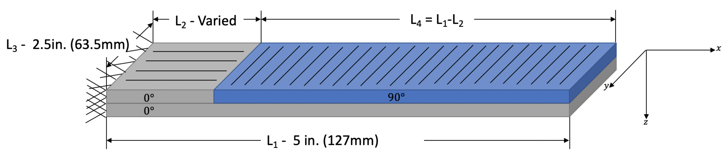
In order to study the effect of introducing symmetry on bistable laminates, a two ply rectangular laminate was used as the basis for the primary design of experiment in this study. The laminates studied were 2.5 in. × 5.0 in. (63.5 mm × 127 mm) two ply laminates that had a symmetric and asymmetric portion, as shown below in Figure 3. The laminate was clamped on one edge, and the dimension was varied between 0 inches (0 mm) (i.e., completely asymmetric) and 5.0 inches in 0.125 inch (3.175 mm) increments. This gives a total of 41 different lay-up geometries, of which five sets were made for a total of 205 laminates.
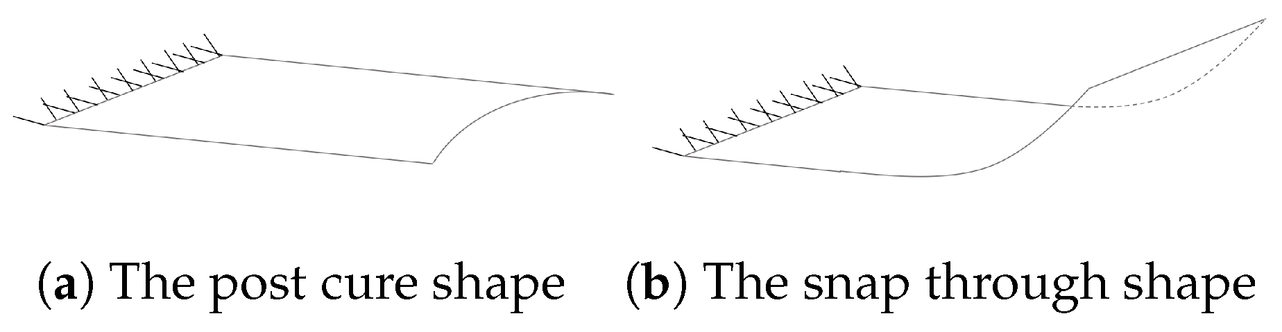
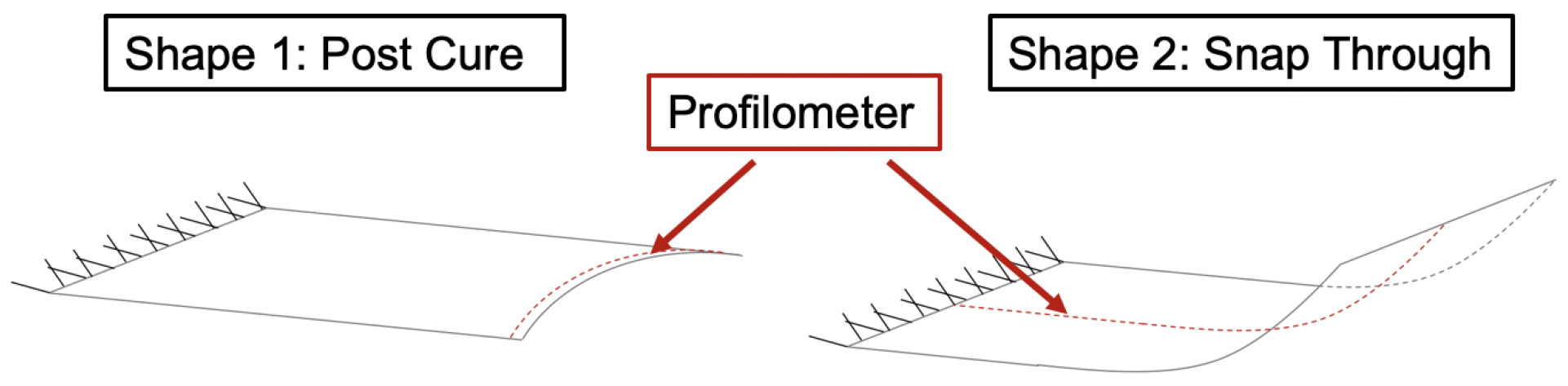
The goal was to understand the effect of introducing symmetry, by measuring the curvatures of the two stable positions with a profilometer, if the sample was indeed bistable. If the sample was bistable, then the curvatures of both the post cure and the snap through shapes were measured. The post cure and snap through shapes are shown in Figure 4. If the sample was not bistable, then only the post-cure shape existed and therefore was measured. All of the laminates were made via the vacuum bagging process with DA409U G35-150 pre-preg carbon fiber.
2.2. Profilometer Setup
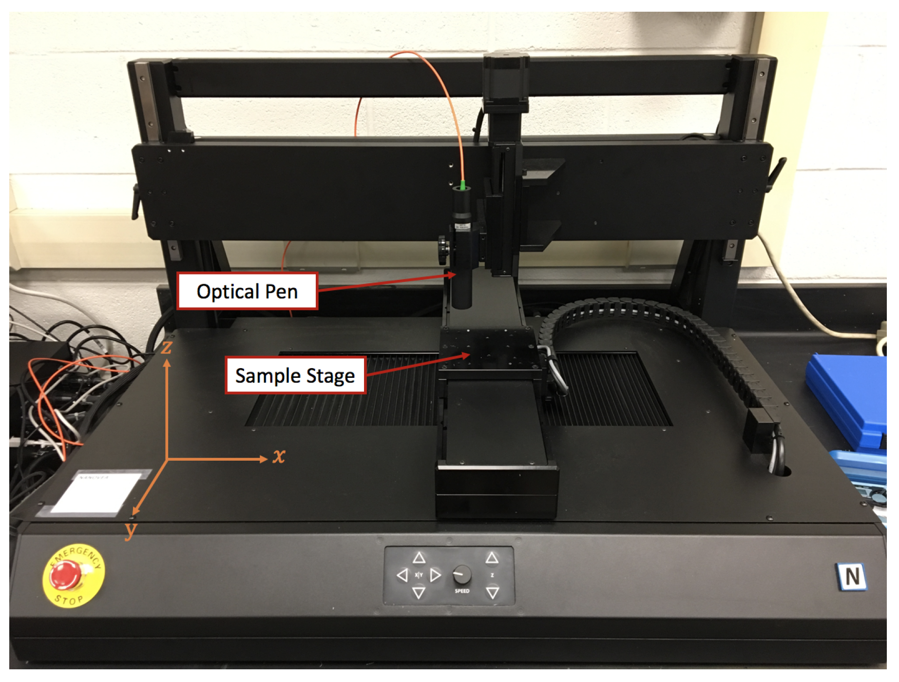
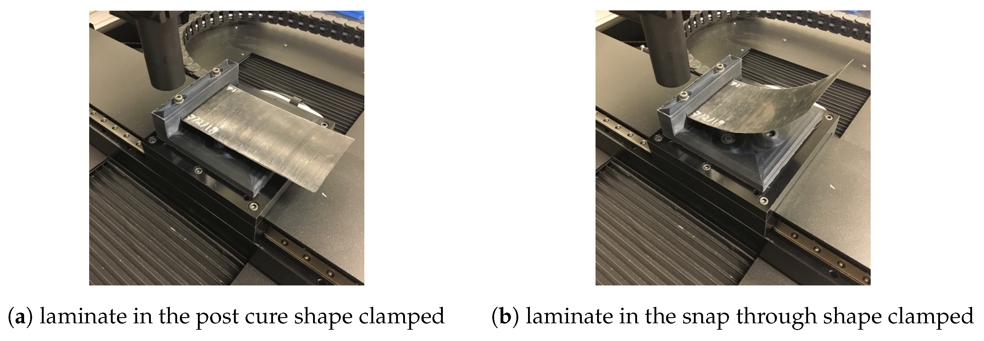
To measure the curvatures under a fixed boundary condition, a Nanovea ST500 Profilometer (Irvine, CA, USA) was used, shown in Figure 5. The Nanovea profilometer uses an optical pen to measure distance. The optical pen works via Chromatic Confocal optical technology (axial chromatism) to measure surface profiles with a possible resolution of a fifth of a micron. An FDM (Fused-Deposition-Modeling) 3D-printed fixture was made to clamp the symmetric edge of the laminates thereby imposing the fixed exterior boundary condition. This fixture was bolted onto the stage of the profilometer, which can move in the x–y directions. The 3D-printed fixture clamped down on 0.0625 in. (1.59 mm) of the short edge of the laminate. Profile scans were done for all 205 laminates (except for the five totally symmetric laminates of each set) to capture the snap through and post cure curvatures. The snap through curvatures were measured from the clamped edge to the opposing free edge of the laminate, and the post cure curvatures were measured across the width of the free edge of the laminate, approximately 1 mm from the actual edge, as shown in Figure 6. The laminates clamped in the fixture in the post cure and snap through shape are shown in Figure 7.
Defining the Curvatures
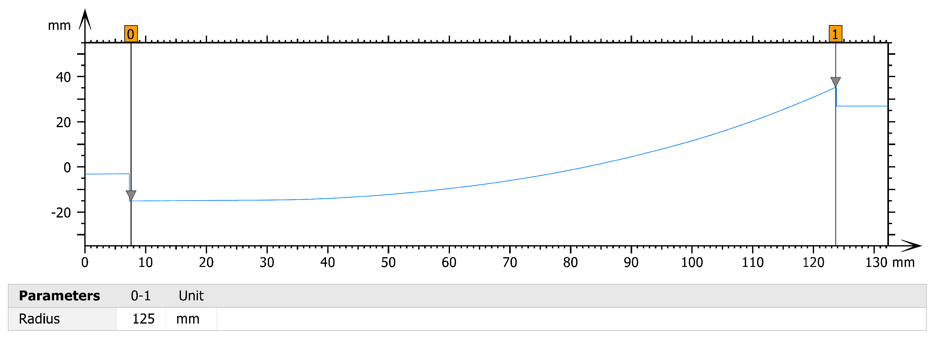
A purely asymmetric laminate has close to constant curvature in each equilibrium shape [2]. As symmetry is introduced in the laminates, the curvatures of the snap through shapes change and no longer have constant curvature, but rather the curvature varies throughout the laminate. The post processing software of the profilometer determines the radius of curvature of a profile by fitting a circle to the profile via the least squares method, where the points of the circle are aligned vertically with the points of the profile, and the curvatures are then calculated from the radii of curvature. The entire profile of the snap through shape was used to determine the snap through curvature. Thus, as symmetry is being introduced and the curvature becomes non-constant, a single curvature value is being assigned to a profile that does not have constant curvature. Therefore, the snap through curvatures reported here can be considered as representative curvatures of the snap through shape. The reason for reporting a representative curvature is due to how the asymmetric region affects the symmetric region. The curvature caused by the asymmetric region affects the symmetric region, and thus some curvature is induced in the symmetric region. The extent to which curvature is induced in the symmetric region is not constant, and thus determining the exact point where the straight portion of the laminate ends and where the curved section starts is not always straightforward. Thus, for simplicity in comparing the snap through shapes of the laminates to one another, the entire profile was used to generate a representative snap through curvature. Figure 8 shows the snap through profile of laminate sample #160 with a symmetric length of 1.0 in. (25.4 mm). In Figure 8, it is not necessarily clear where the laminate begins to be curved, thus the entire laminate is used to obtain a representative snap through curvature.
3. Results
A total of 400 laminate radii of curvature were measured with the Nanovea ST500 Profilometer, those being the snap through and post cure radii of curvature of the five sets laminates. To obtain the curvature, the definition of curvature was used, where the curvature k is defined as
where R is the radius of curvature [17]. Once the curvatures were calculated, plots were made to compare the curvatures to the amount of symmetry in the laminates.
3.1. Representative Snap through Curvatures
The representative snap through curvatures of the laminates were of primary interest, as their presence denotes the existence of bistability. Figure 9 and Figure 10 plot the snap through radius of curvature and curvature of the laminate versus the precent symmetry, where the precent symmetry is defined as:
where is the length of the symmetric portion of the laminate and varied from zero to five inches (0 to 127 mm), and is the overall length of the laminate, five inches (127 mm). The curvatures are plotted with error bars showing plus and minus one standard deviation. The variance in the curvatures which is shown via the standard deviation in Figure 9, Figure 10 and Figure 11 is discussed in detail in Section 3.3.
A second order polynomial is fit onto the data in Figure 10 with an value of 0.98, where is a statistical determination of the goodness of fit of the polynomial to the data, with an value of 1 being a perfect fit. The polynomial relationship is as follows:
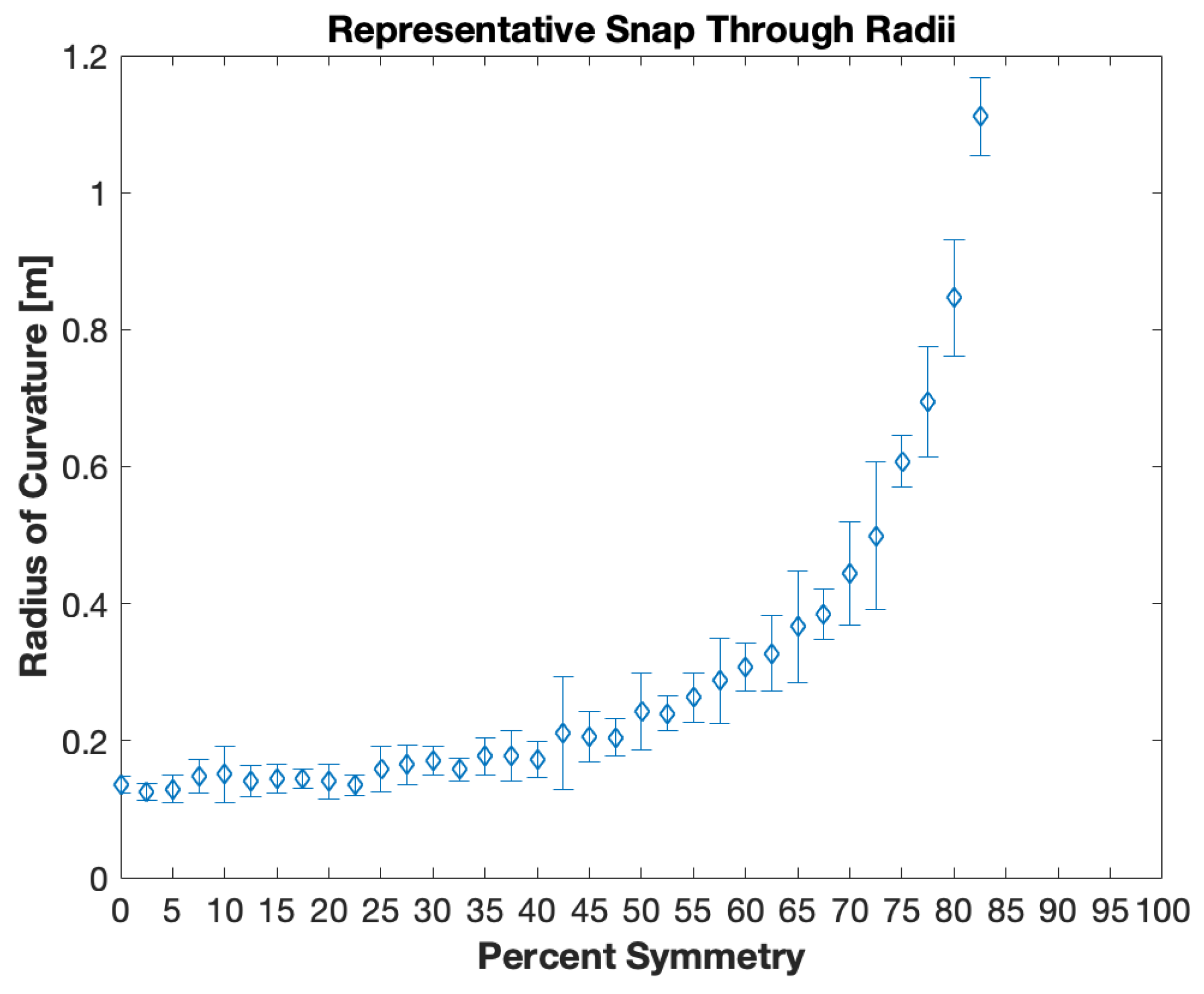
where P is the percent symmetry. The physical meaning behind the coefficients of the polynomial is unknown, and additional research is required to determine their meaning. It can be seen that, as the percent symmetry in the laminate increases, the representative snap through curvature decreases. It is likely that the values for these coefficients are dependent on the material properties and as well as the parameters which affect bistability, such as the laminate length, width, and thickness, as well as the lamina layup orientation. It should be noted that laminates with a symmetric portion beyond 104.775 mm (4.125 inches) were not bistable and thus not plotted on Figure 10. Thus, Figure 10 shows that bistability is exhibited for laminates that are up to 83% symmetric (up to a symmetric length of 4.125 inches (104.775 mm)), although with decreased curvature as stated. In addition, Figure 10 shows that up to around 20% symmetry can be introduced without an appreciable loss of curvature. It must be stated that Figure 10 can only be considered valid for the exact laminate geometry that was tested. In addition, not every sample of the five samples with 83% symmetry was bistable. This was likely due to slight variation in the dimensions of the symmetric/asymmetric portion, due to the manual manufacturing process. Further experiments would need to be carried out to see if such a relationship holds true if the overall geometry of the laminate is changed, or if the number of plies is changed.
3.2. Post Cure Curvatures
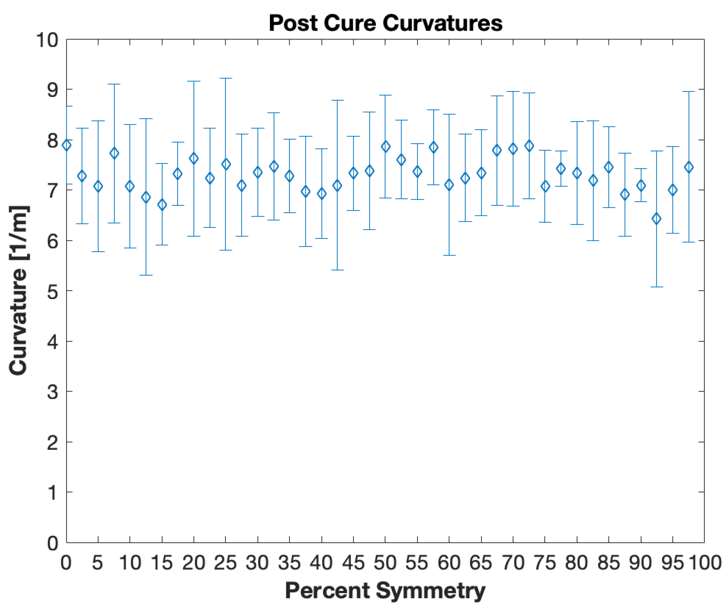
The post cure curvatures were also measured. Figure 11 plots the post cure curvature of the laminate versus the percent symmetry in the laminate. Again, these are the curvatures measured at the asymmetric end of the laminate.
As seen in Figure 11, the post cure curvature values stay approximately the same regardless of the percent symmetry, and their value is similar to the snap through curvatures of the laminates with 20% or less symmetry introduced. Except for the case, however, when there is no longer any asymmetry in the laminate, then the laminate ceases to be curved as all of the fibers are going in the same direction. This result that the post cure curvature at the asymmetric end remains approximately constant is likely due to the weakness in bending about the x-axis of the symmetric region such that the asymmetric portion is able to be curved about the x-axis without a strong reaction against taking that curvature from the symmetric region. In addition, the curvature is being measured 1 mm from the free edge of the laminate, as described in Figure 6 and, therefore, the curvature is being measured where the effect of the asymmetry is the strongest. If the symmetric portion layup scheme were changed from [0/0], this result would likely be different, such as with a symmetric layup scheme of [45/45] or [90/90].
3.3. Sources of Error and Variance
As can be seen from Figure 10, the laminates with larger curvature had high amounts of variance compared to the laminates with smaller curvatures. The post cure curvatures also showed a large amount of variance. There are multiple sources of this variation. Brampton et al. show that the curvature of an asymmetric composite laminate is sensitive to uncertainties in the Young’s Modulus, the thermal expansion coefficients, the ply thickness, and temperature changes from the elevated cure temperature [18]. Brampton et al. also show that the curvatures of an asymmetric composite laminate are highly sensitive to moisture ingress [18]. This sensitivity to moisture ingress was experienced during the course of this study. There is a marked decrease in the curvature over time as the samples absorb moisture. Due to this high sensitivity to moisture ingress, all experimental measurements were conducted within 24 hours of curing. Additionally, error is induced due to the manual manufacturing process. There naturally exists small variation in the dimensions of the laminates due to the fact that the pre-preg fibers were cut and layed-up manually.
3.4. Finite Element Analysis
In order to verify the experimental results, finite element analysis was done to obtain the post cure and snap-through shapes of the laminates. For all of the simulations done in this study, the finite element software ABAQUS CAE 6.14 was used. To obtain the curvatures, post processing was done using a Matlab script. The material properties used for the initial simulations are listed in Table 1.
The properties of AS4 pre-pre were chosen as they are close to the DA409U G35-150 pre-preg that was used to fabricate the laminates. For the convenience of inputting the dimensions in millimeters in Abaqus, the units for the material properties are given in Newtons per millimeter squared instead of Pascals. Abaqus itself does not ask for units so consistency is required on the users’ part to ensure accuracy. Thus, the material properties had to be adjusted to account for the usage of millimeters rather than meters.
The steps simulated were the cool down process, the release from the mold and imposition of the fixed edge boundary condition, and the snap-through. As it is during the cool down portion of the curing process that the residual stresses build up due to the dissimilar thermal expansion coefficients, only the cool down portion of the curing process needs to be simulated and not the entire curing process. Due to the dynamic nature of the snap through, Abaqus’ explicit solver was used for all simulations.
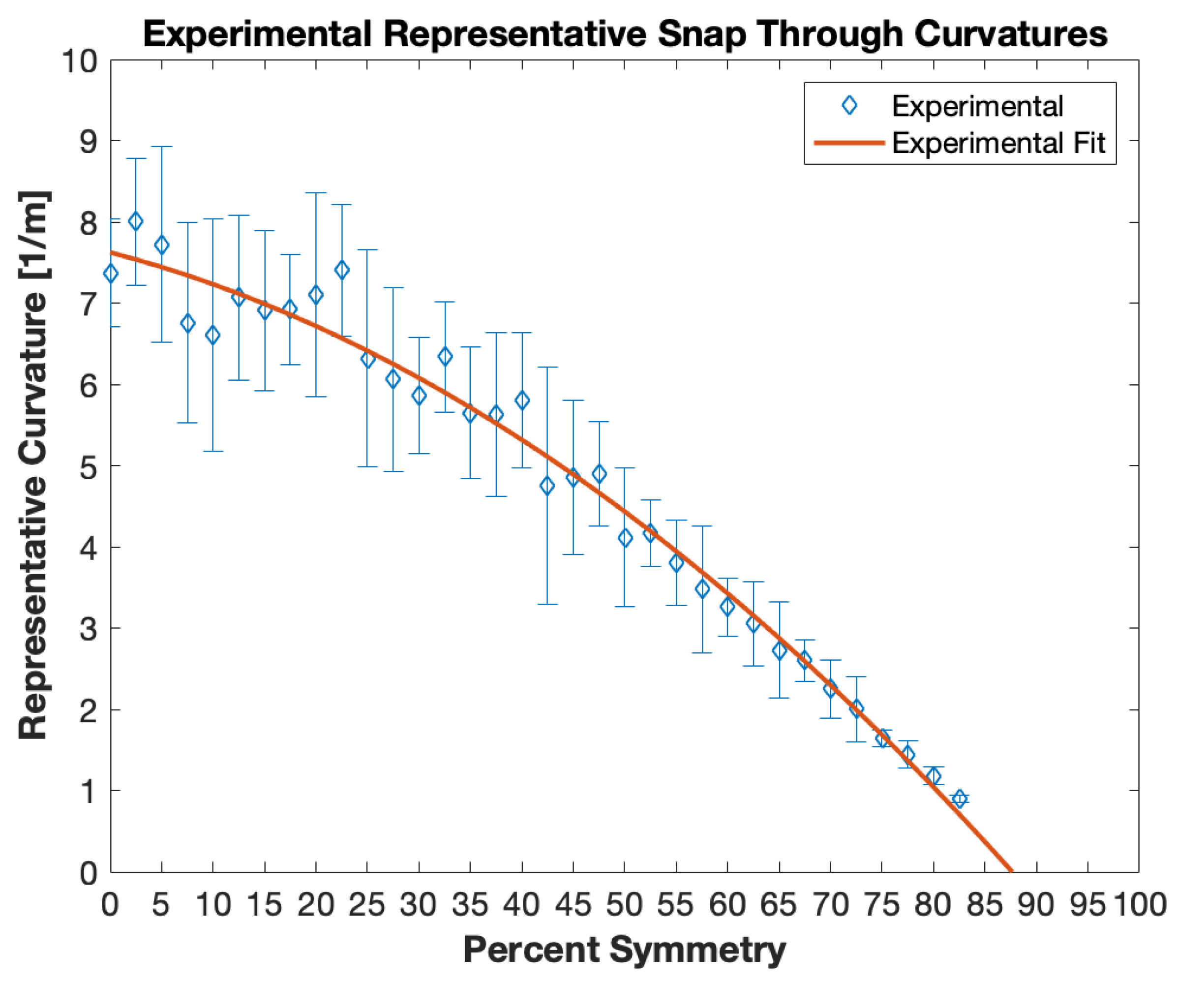
The Matlab script then extracted x–z coordinates of the centerline of each laminate of the post cure shape, fit a least-squared circle to the profile, and output the radius of curvature and the curvature. Thus, the snap through curvatures of the simulations could be directly compared to the experimental results. Figure 12 compares the initial simulation results with the experimental results.
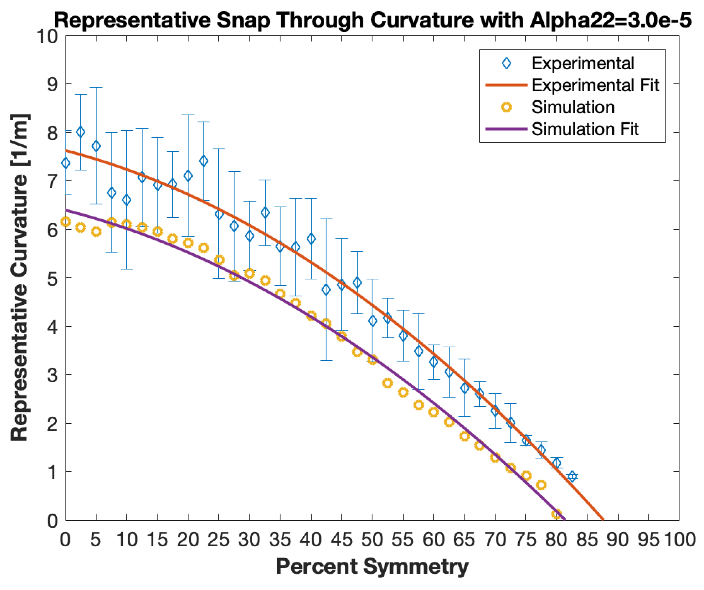
As shown in Figure 12, the simulated laminates exhibited bistability up to 80% symmetry (symmetric length = 4.0 in. (101.6 mm)) and no bistability thereafter, where as the experiments showed bistability up to 83% (symmetric length = 4.125 in. (104.775 mm)). Figure 12 shows that the initial simulation results have a similar trend to the experimental results, but the curvatures are offset down by around 15–20%. As stated previously, it has been shown by Brampton et al. that the curvatures and bistability of bistable laminates are highly sensitive to a variety of parameters [18]. One of these parameters is the thermal expansion coefficient perpendicular to the fibers, . As the true value of was not known for the pre-preg used to fabricate the laminates, a sensitivity study was done in Abaqus to investigate the affect of on the snap through curvatures, and to determine whether changes in would allow for better agreement between the simulations and experiments.
Preliminary Coefficient of Thermal Expansion Thermal Sensitivity Study
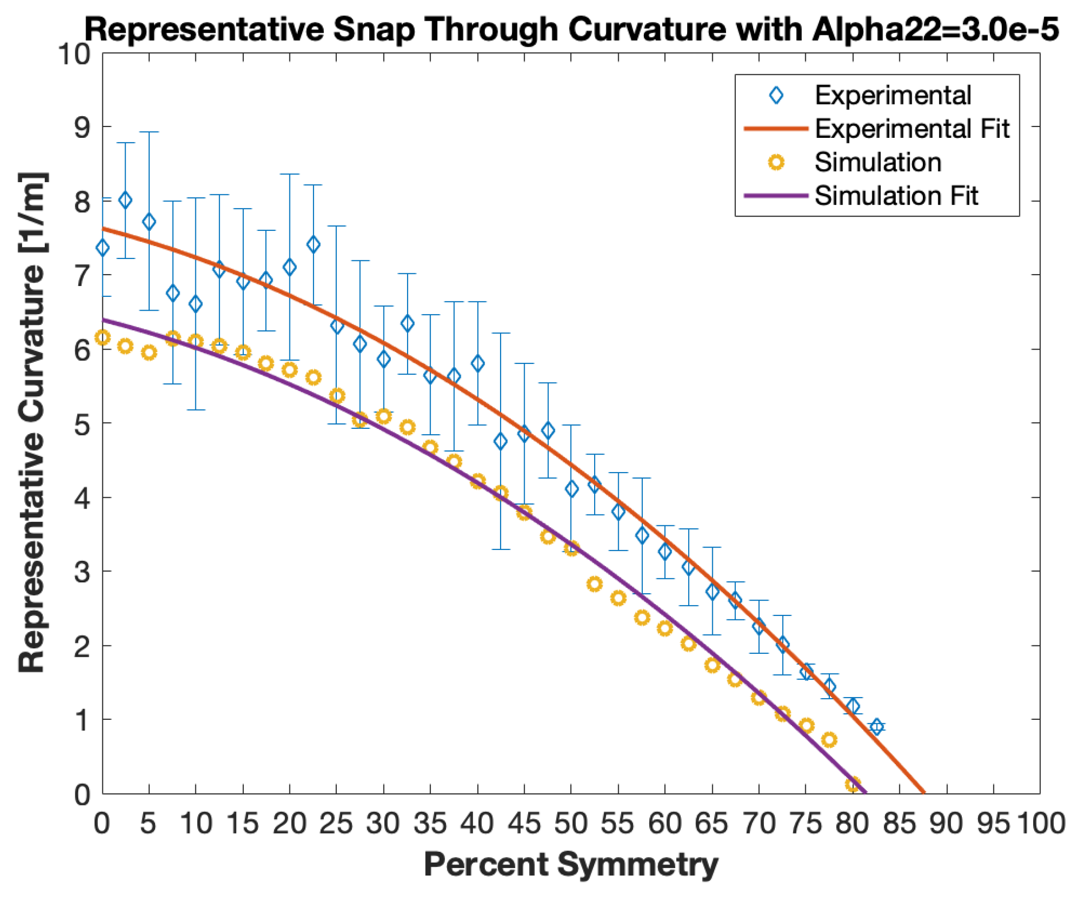
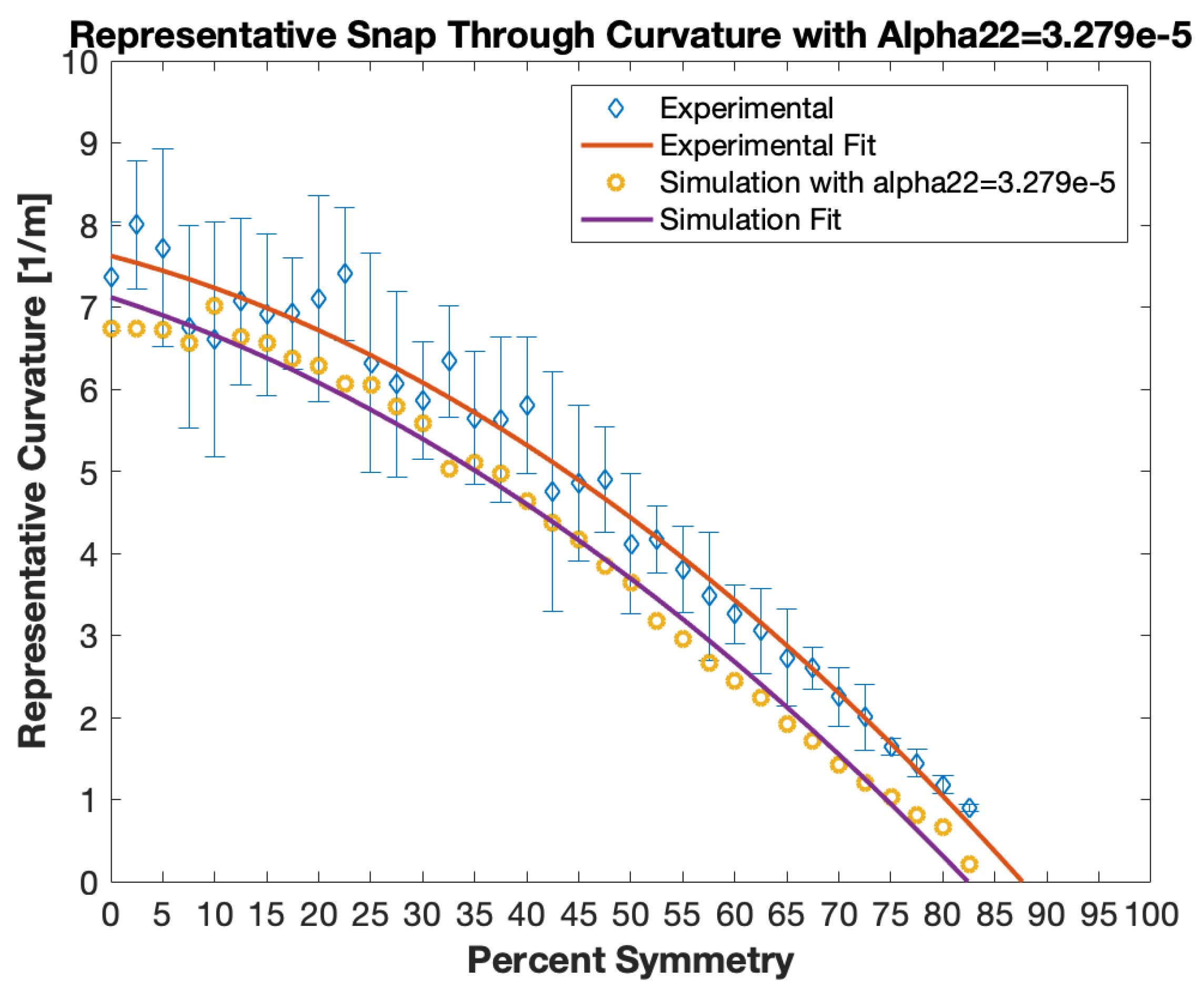
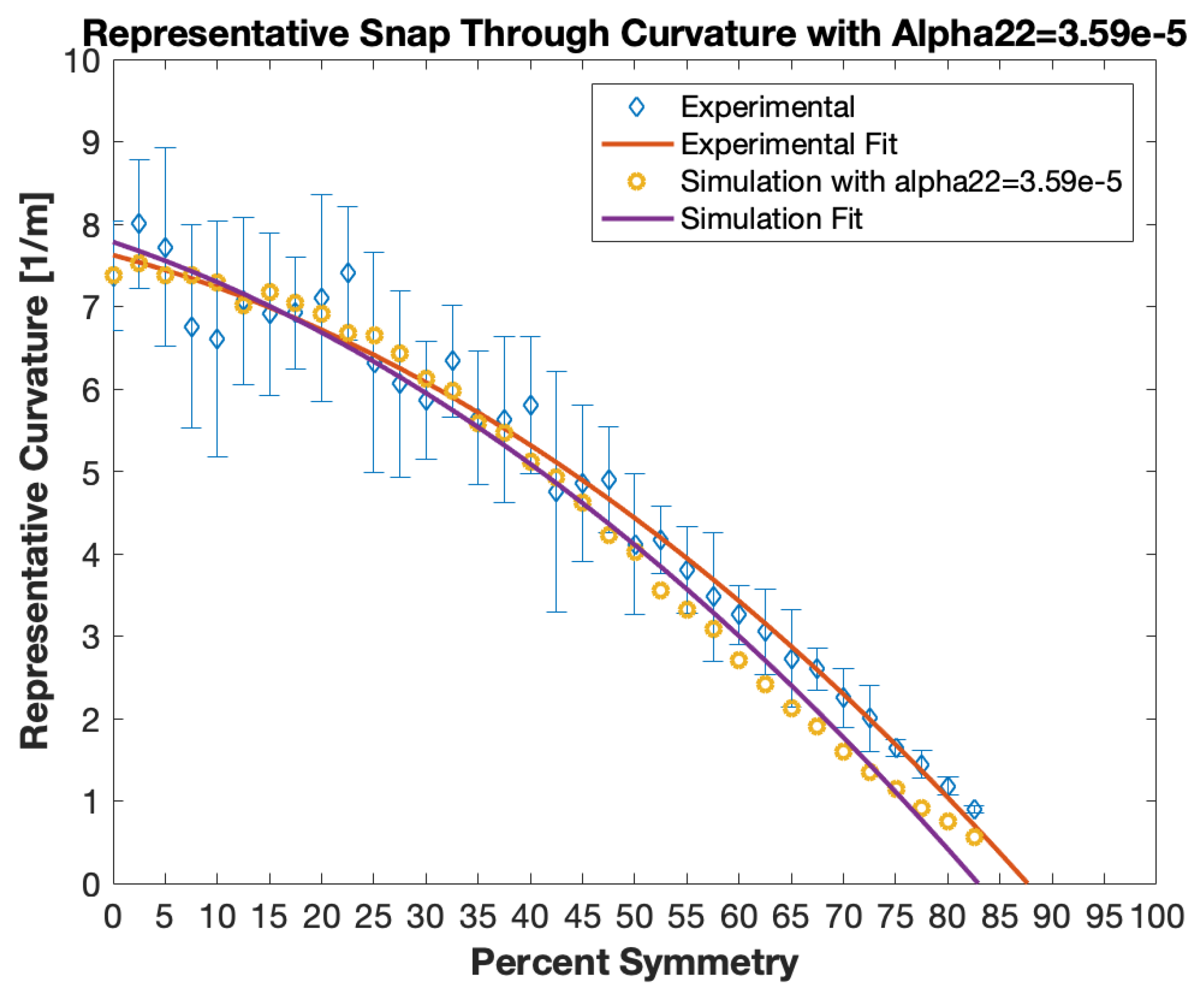
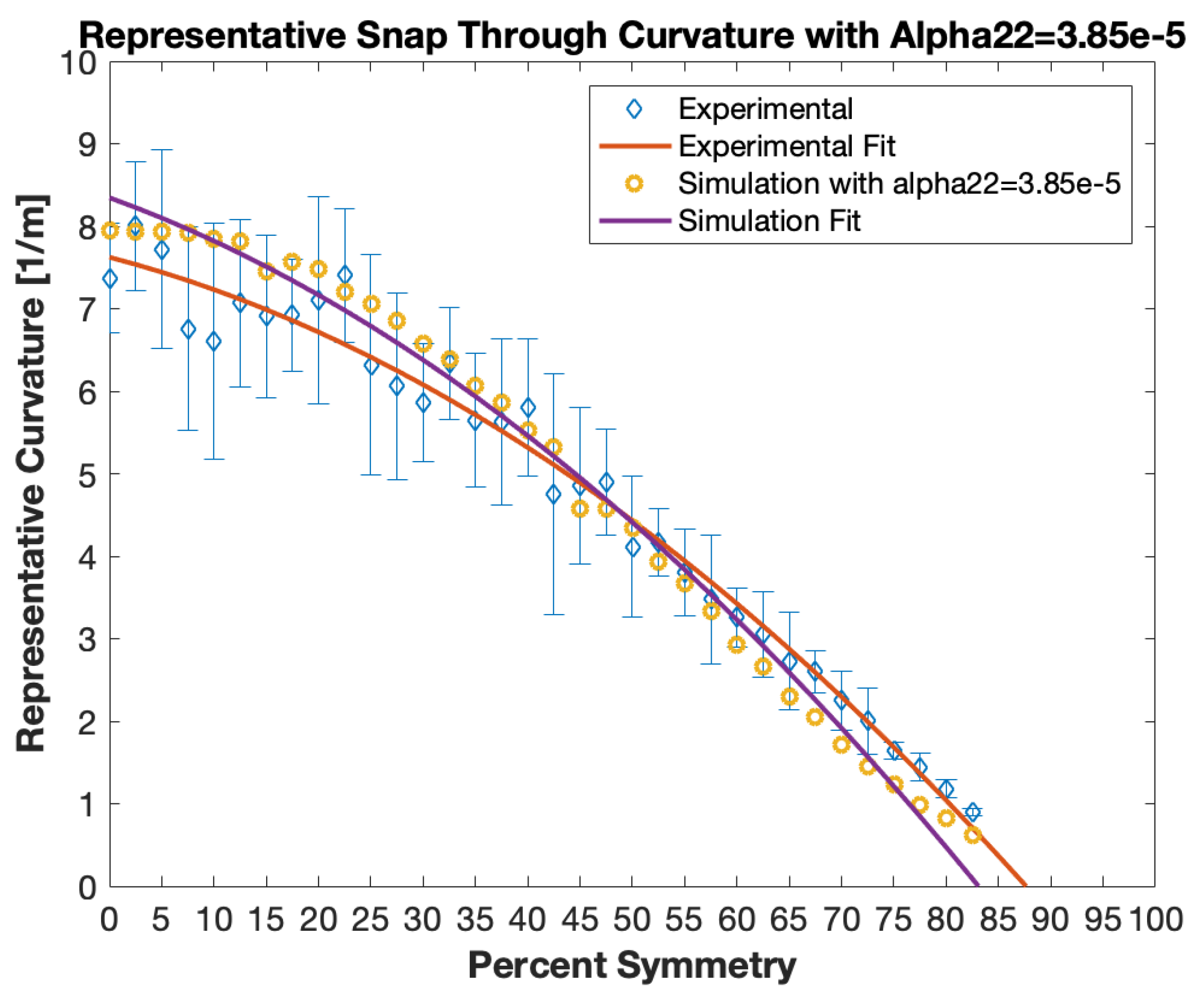
Several values were used for to study its affect. The values ranged between and . The values were chosen by calculating the average percent error between the simulation curvatures and the experimental curvatures, and then increasing by that percentage. The following plots, Figure 13, Figure 14, Figure 15 and Figure 16, show the results for each value.
Increasing up to resulted in the laminate configuration with a symmetric length = 4.125 in. (104.775 mm)) becoming bistable, as seen in Figure 15, which agrees with the experimental results. The sensitivity study showed that an value of resulted in the closest agreement with the experimental results.
4. Conclusions
The goal of this study was to gain more understanding on how introducing a symmetric region between a clamped edge boundary condition and an asymmetric region affect the bistability and curvature of a combined symmetric asymmetric laminate. The results showed that, as the amount of symmetry in the laminate increased, the representative snap through curvature decreased. It was discovered that laminates with up to 83% symmetry exhibited bistability. In addition, it was found that, in laminates with up to 20% symmetry, the representative snap through curvature decreased very little. This finding is significant because it shows that up to a 20% symmetric region can be implemented between a clamped edge boundary condition without appreciable loss of snap through curvature. The experimental results showed that, for the laminates with up to 20% symmetry, there was a high amount of statistical variation. The post cure curvatures remained relatively constant, regardless of the amount of symmetry. The post cure curvatures also showed a high amount of statistical variation. The variation in the curvatures of the laminate are most likely due to the affects of moisture ingress, human-error in the experimental setup, as well as the inherent variation between laminates due to the manual fabrication process.
Simulations were conducted in Abaqus 6.14 CAE to replicate the experiments. The initial simulation results showed good correlation with the experiments but with lower curvature values. Due to the known sensitivity of the curvatures to the thermal expansion coefficient in the direction perpendicular to the fibers, , a sensitivity study was done to see the effect of changing . This sensitivity study showed that changing does indeed affect the snap through curvatures, and it was found that an value of best matched the experimental results.
Certain phenomena were observed within the experimental portion as well as the simulation portion of this study that were not investigated. The physical meaning behind the coefficients of the polynomial equation fitted to the plot of snap through curvature versus symmetric length in Figure 10 was not investigated. Further research would need to be done to derive a physical meaning and understanding of these coefficients. It is likely that the values for these coefficients are dependent on the material properties and as well as the parameters that affect bistability, such as the laminate length, width, and thickness, as well as the lamina layup orientation.
Author Contributions
This research was conducted by G.K. and O.M. Conceptualization, O.M.; Methodology, O.M. and G.K.; Software, G.K.; Validation, G.K., and O.M.; Formal Analysis, G.K.; Investigation, G.K.; Resources, O.M.; Data Curation, G.K. and O.M.; Writing-Original Draft Preparation, G.K.
Funding
This research received no external funding.
Conflicts of Interest
The authors declare no conflict of interest.
References
- Hyer, M.W. Some Observations on the Cured Shape of Thin Unsymmetric Laminates. J. Compos. Mater. 1981, 15, 175–194. [Google Scholar] [CrossRef]
- Hyer, M.W. Calculation of the Room-Temperature Shapes of Unsymmetric Laminates. J. Compos. Mater. 1981, 15, 296–310. [Google Scholar] [CrossRef]
- Jones, R.M. Mechanics of Composite Materials, 2nd ed.; CRC Press: Boca Raton, FL, USA, 1998. [Google Scholar]
- Hyer, M.W. The Room-Temperature Shapes of Four-Layer Unsymmetric Cross-Ply Laminates. J. Compos. Mater. 1982, 16, 318–340. [Google Scholar] [CrossRef]
- Hamamoto, A.; Hyer, M.W. Non-Linear Temperature-Curvature Relationships for Unsymmetric Graphite-Epoxy Laminates. Int. J. Solids Struct. 1987, 23, 919–935. [Google Scholar]
- Jun, W.J.; Hong, C.S. Effect of residual shear strain on the cured shape of unsymmetric cross-ply thin laminates. Compos. Sci. Technol. 1990, 38, 55–67. [Google Scholar] [CrossRef]
- Ren, A.L.; Parvizi, Z.L. Cured shape of cross-ply composite thin shells. J. Compos. Mater. 2003, 37, 1801–1820. [Google Scholar] [CrossRef]
- Jun, W.J.; Hong, C.S. Cured shape of unsymmetric laminates with arbitrary lay-up angles. J. Reinf. Plast. Compos. 1992, 11, 1352–1366. [Google Scholar] [CrossRef]
- Schlecht, M.; Schulte, K.; Hyer, M.W. Advanced Calculation of the Room- Temperature Shapes of Thin Unsymmetric Composite Laminates. Compos. Struct. 1995, 32, 627–633. [Google Scholar] [CrossRef]
- Betts, D.N.; Salo, I.T.; Bowen, C.R.; Kim, H.A. Characterisation and Modelling of the Cured Shapes of Arbitrary Layup Bistable Composite Laminates. Compos. Struct. 2010, 92, 1694–1700. [Google Scholar] [CrossRef]
- Giddings, P.F.; Bowen, C.R.; Salo, A.I.T.; Kim, H.A.; Ive, A. Bistable Composite Laminates: Effects of Laminate Composition on Cured Shape and Response to Thermal Load. Compos. Struct. 2010, 92, 2220–2225. [Google Scholar] [CrossRef]
- Dano, M.L.; Hyer, M.W. Thermally Induced Deformation Behavior of Unsymmetric Laminates. Int. J. Solids Struct. 1998, 35, 2101–2120. [Google Scholar] [CrossRef]
- Tawfik, S.; Tan, X.; Ozbay, S.; Armanios, E. Anticlastic Stability Modeling for Cross-Ply Composites. J. Compos. Mater. 2007, 41, 1325–1338. [Google Scholar] [CrossRef]
- Tawfik, S.A.; Stefan Dancila, D.; Armanios, E. Planform effects upon the bistable response of cross-ply composite shells. Compos. A Appl. Sci. Manuf. 2011, 42, 825–833. [Google Scholar] [CrossRef]
- Wang, B.; Ge, C.; Fancey, K.S. Snap-through behaviour of a bistable structure based on viscoelastically generated prestress. Compos. B Eng. 2017, 114, 23–33. [Google Scholar] [CrossRef]
- Dano, M.L.; Hyer, M.W. Snap-Through of Unsymmetric Fiber-Reinforced Composite Laminates. Int. J. Solids Struct. 2002, 39, 175–198. [Google Scholar] [CrossRef]
- Kline, M. Calculus: An Intuitive and Physical Approach, 2nd ed.; John Wiley and Sons, Inc.: Hoboken, NJ, USA, 1977. [Google Scholar]
- Brampton, C.J.; Betts, D.N.; Bowen, C.R.; Kim, H.A. Sensitivity of bistable laminates to uncertainties in material properties, geometry and environmental conditions. Compos. Struct. 2013, 102, 276–286. [Google Scholar] [CrossRef] [Green Version]
Figure 1.
Cylindrical shape (A) and cylindrical shape of opposite sign and perpendicular axes of curvature (B) [2].
Figure 1.
Cylindrical shape (A) and cylindrical shape of opposite sign and perpendicular axes of curvature (B) [2].

Figure 2.
Pinned and/or roller boundary conditions used for characterizing snap through force [14].
Figure 2.
Pinned and/or roller boundary conditions used for characterizing snap through force [14].

Figure 3.
Schematic showing the lay-up structure of the rectangular laminate studied.

Figure 4.
The post cure and snap through shapes.

Figure 5.
The Nanovea ST500 profilometer that was used to measure the curvatures of the laminates.

Figure 6.
Schematic showing where the post cure curvature and snap through curvature were measured with the profilometer.
Figure 6.
Schematic showing where the post cure curvature and snap through curvature were measured with the profilometer.

Figure 7.
The post cure and snap through shapes.

Figure 8.
Sample #160 snap through profile taken with the Nanovea profilometer.

Figure 9.
The snap through representative radius of curvature versus the percent symmetry.

Figure 10.
The representative snap through curvature versus the percent symmetry.

Figure 11.
The post cure curvature versus the percent symmetry for all of the laminates studied. Error bars show ± one standard deviation.
Figure 11.
The post cure curvature versus the percent symmetry for all of the laminates studied. Error bars show ± one standard deviation.

Figure 12.
The snap through curvature versus the percent symmetry for all of the laminates simulated and studied that were bistable. Error bars on the experimental points show ± one standard deviation.
Figure 12.
The snap through curvature versus the percent symmetry for all of the laminates simulated and studied that were bistable. Error bars on the experimental points show ± one standard deviation.

Figure 13.
The snap through curvature versus the percent symmetry for all of the laminates simulated and studied that were bistable, using an value of . Error bars on the experimental points show ± one standard deviation.
Figure 13.
The snap through curvature versus the percent symmetry for all of the laminates simulated and studied that were bistable, using an value of . Error bars on the experimental points show ± one standard deviation.

Figure 14.
The snap through curvature versus the percent symmetry for all of the laminates simulated and studied that were bistable, using an value of . Error bars on the experimental points show ± one standard deviation.
Figure 14.
The snap through curvature versus the percent symmetry for all of the laminates simulated and studied that were bistable, using an value of . Error bars on the experimental points show ± one standard deviation.

Figure 15.
The snap through curvature versus the percent symmetry for all of the laminates simulated and studied that were bistable, using an value of Error bars on the experimental points show ± one standard deviation.
Figure 15.
The snap through curvature versus the percent symmetry for all of the laminates simulated and studied that were bistable, using an value of Error bars on the experimental points show ± one standard deviation.

Figure 16.
The snap through curvature versus the percent symmetry for all of the laminates simulated and studied that were bistable, using an value of . Error bars on the experimental points show ± one standard deviation.
Figure 16.
The snap through curvature versus the percent symmetry for all of the laminates simulated and studied that were bistable, using an value of . Error bars on the experimental points show ± one standard deviation.


Table 1.
Material properties of the unidirectional AS4 pre-preg carbon fiber. The units for the stiffnesses are N/mm.
Table 1.
Material properties of the unidirectional AS4 pre-preg carbon fiber. The units for the stiffnesses are N/mm.
| 135,000 | 9500 | 0.3 | 5000 | 7170 | 3970 |
© 2019 by the authors. Licensee MDPI, Basel, Switzerland. This article is an open access article distributed under the terms and conditions of the Creative Commons Attribution (CC BY) license (http://creativecommons.org/licenses/by/4.0/).
Share and Cite
MDPI and ACS Style
Kemmann, G.; Myers, O. An Experimental Investigation of Combined Symmetric-Asymmetric Composite Laminates. J. Compos. Sci. 2019, 3, 71. https://0-doi-org.brum.beds.ac.uk/10.3390/jcs3030071
AMA Style
Kemmann G, Myers O. An Experimental Investigation of Combined Symmetric-Asymmetric Composite Laminates. Journal of Composites Science. 2019; 3(3):71. https://0-doi-org.brum.beds.ac.uk/10.3390/jcs3030071
Chicago/Turabian StyleKemmann, Guy, and Oliver Myers. 2019. "An Experimental Investigation of Combined Symmetric-Asymmetric Composite Laminates" Journal of Composites Science 3, no. 3: 71. https://0-doi-org.brum.beds.ac.uk/10.3390/jcs3030071