Evaluation of Single-Lap and Block Shear Test Methods in Adhesively Bonded Composite Joints


Abstract
:1. Introduction
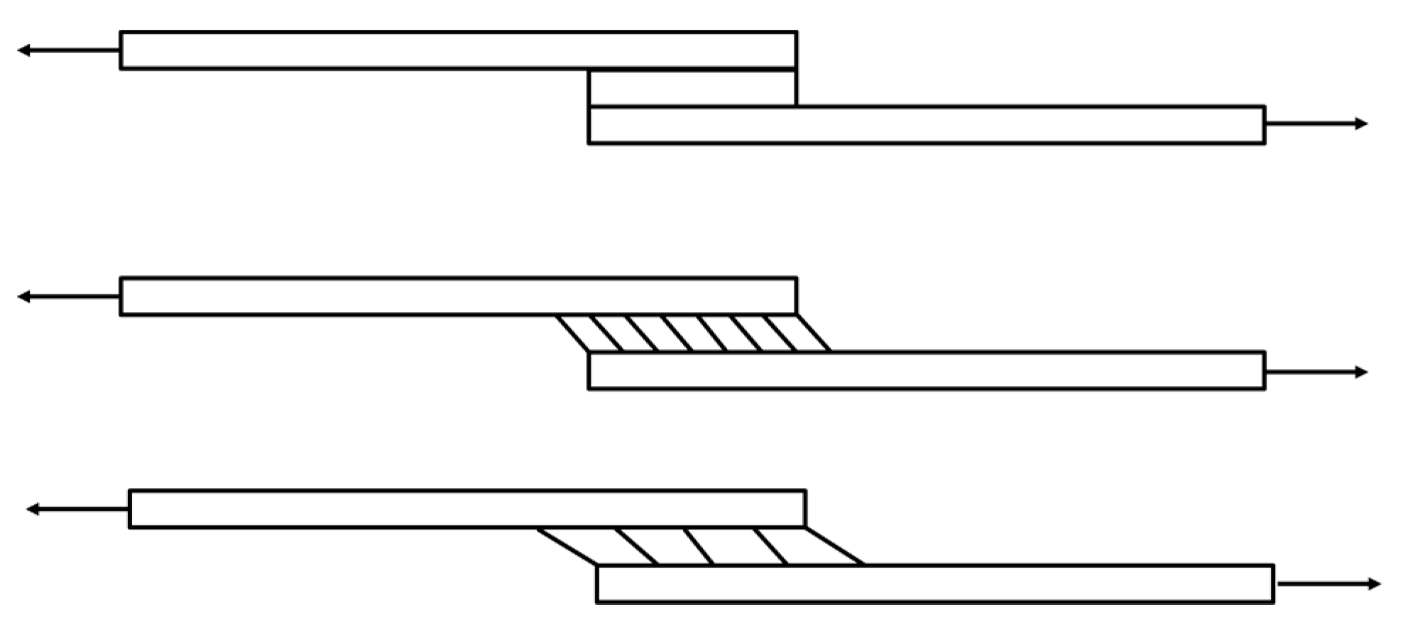
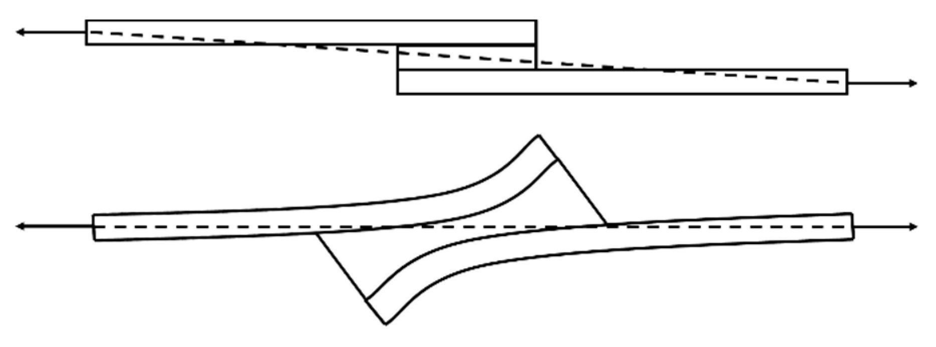
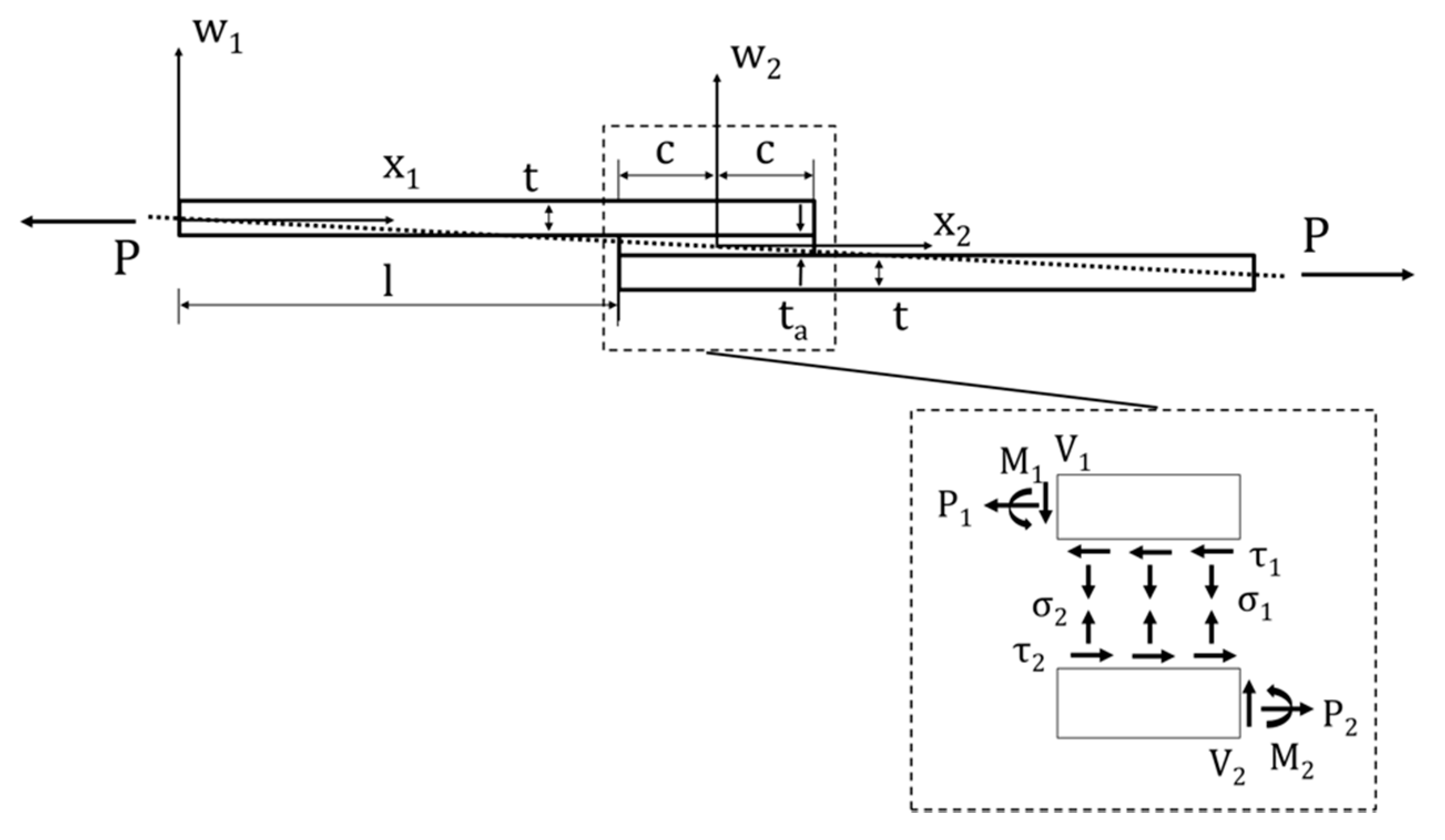
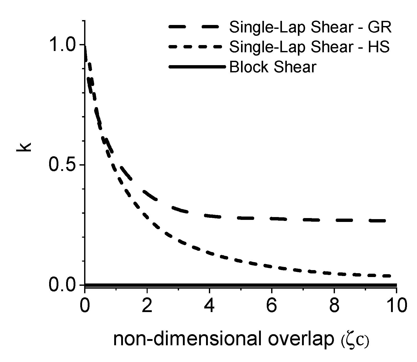
2. Analytical Models for Adhesively Bonded Joints
3. Finite Element Model
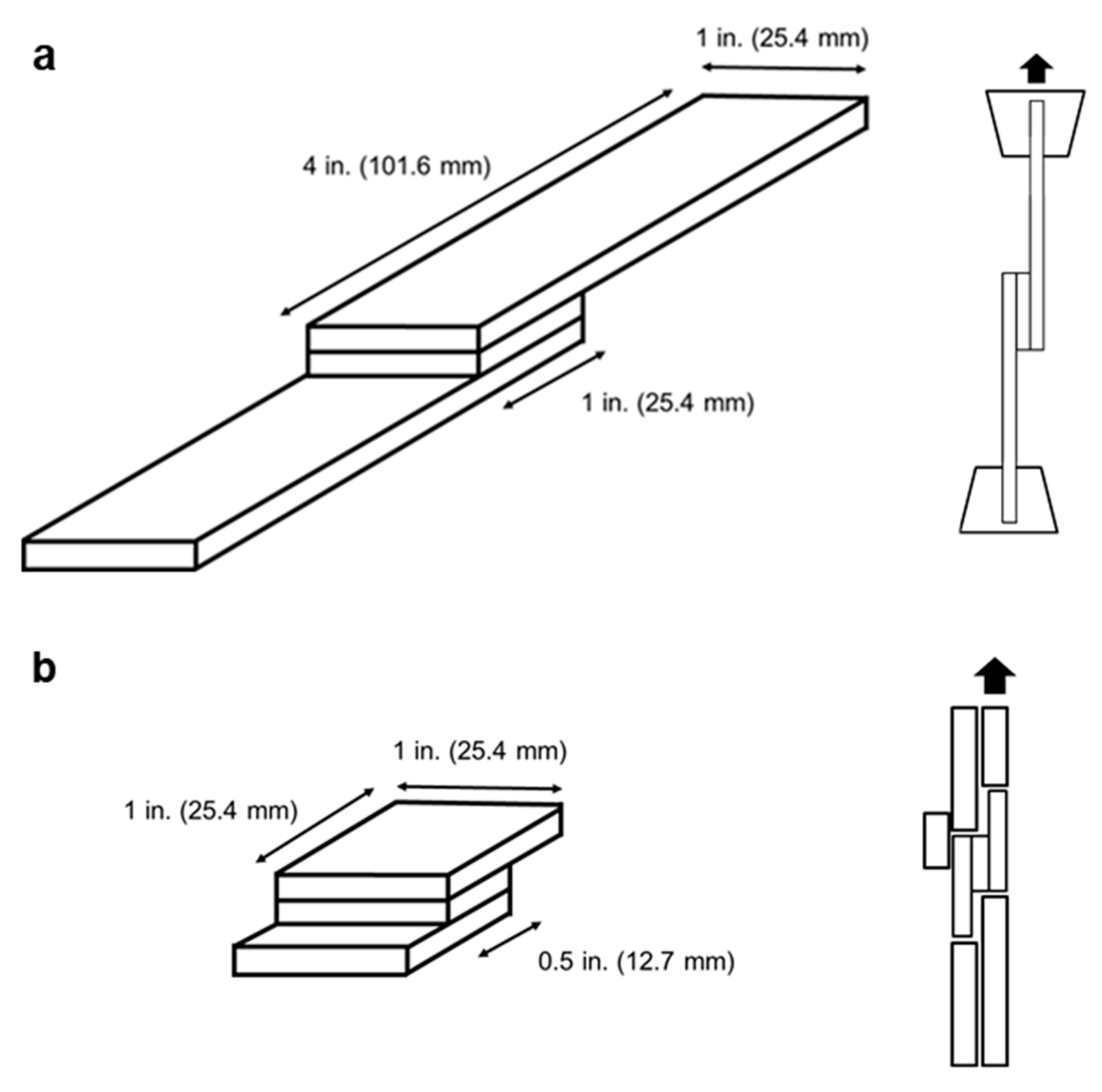
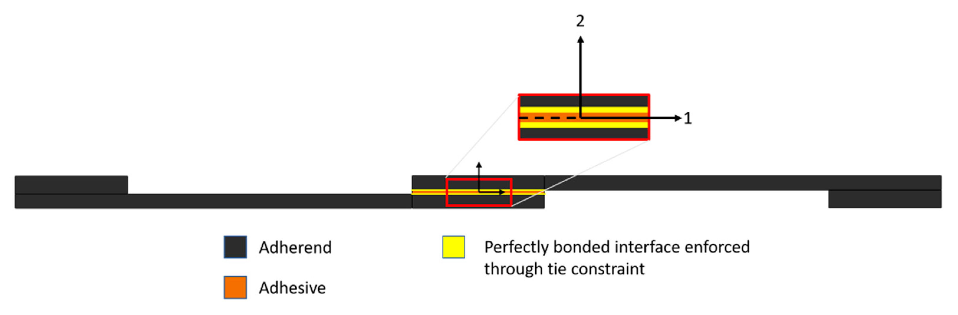
3.1. Single-Lap Shear
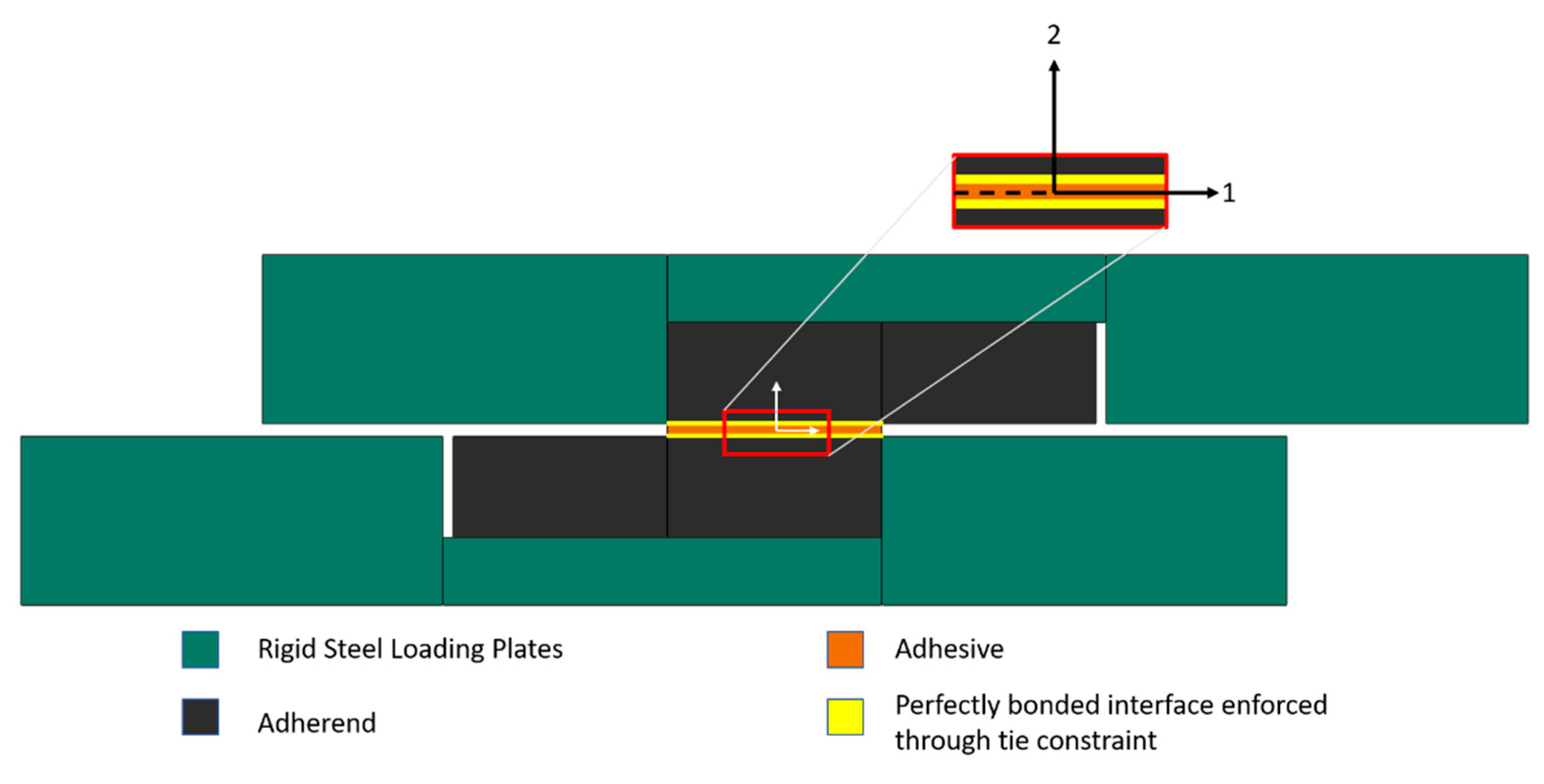
3.2. Block Shear
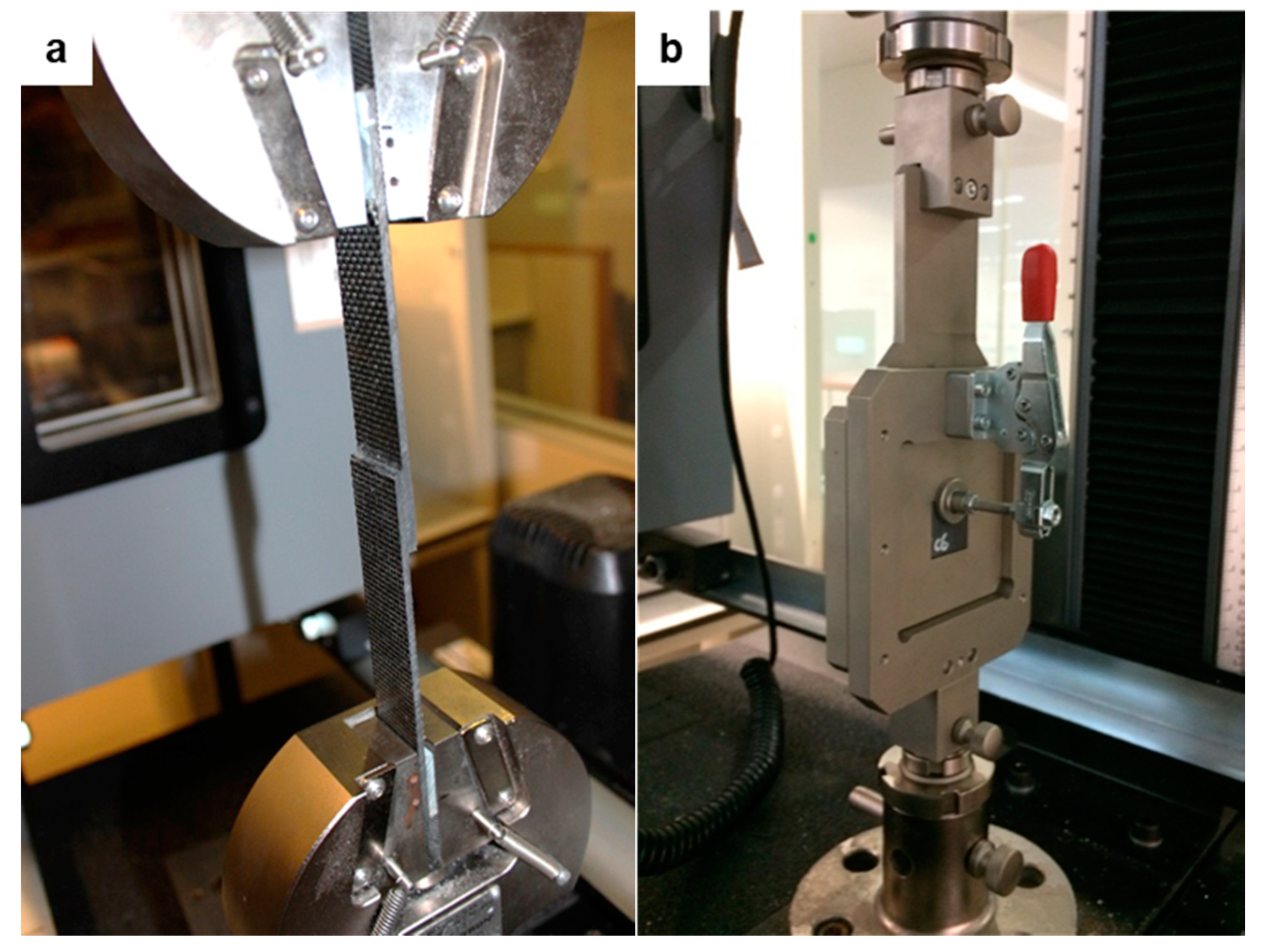
4. Experimental Methods
4.1. Materials
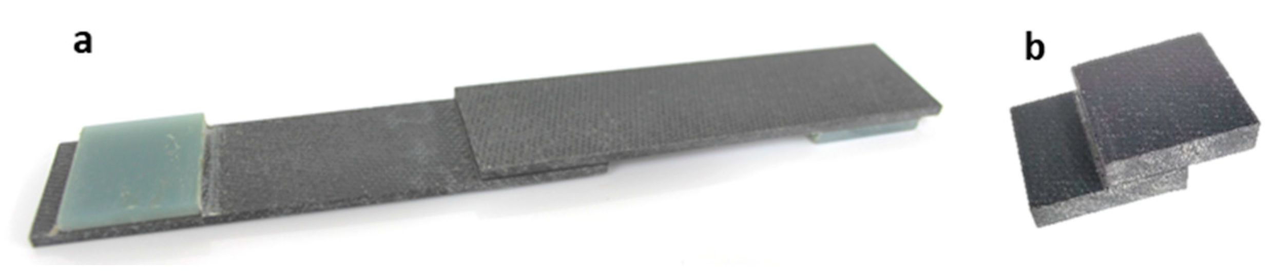
4.2. Manufacturing
5. Results
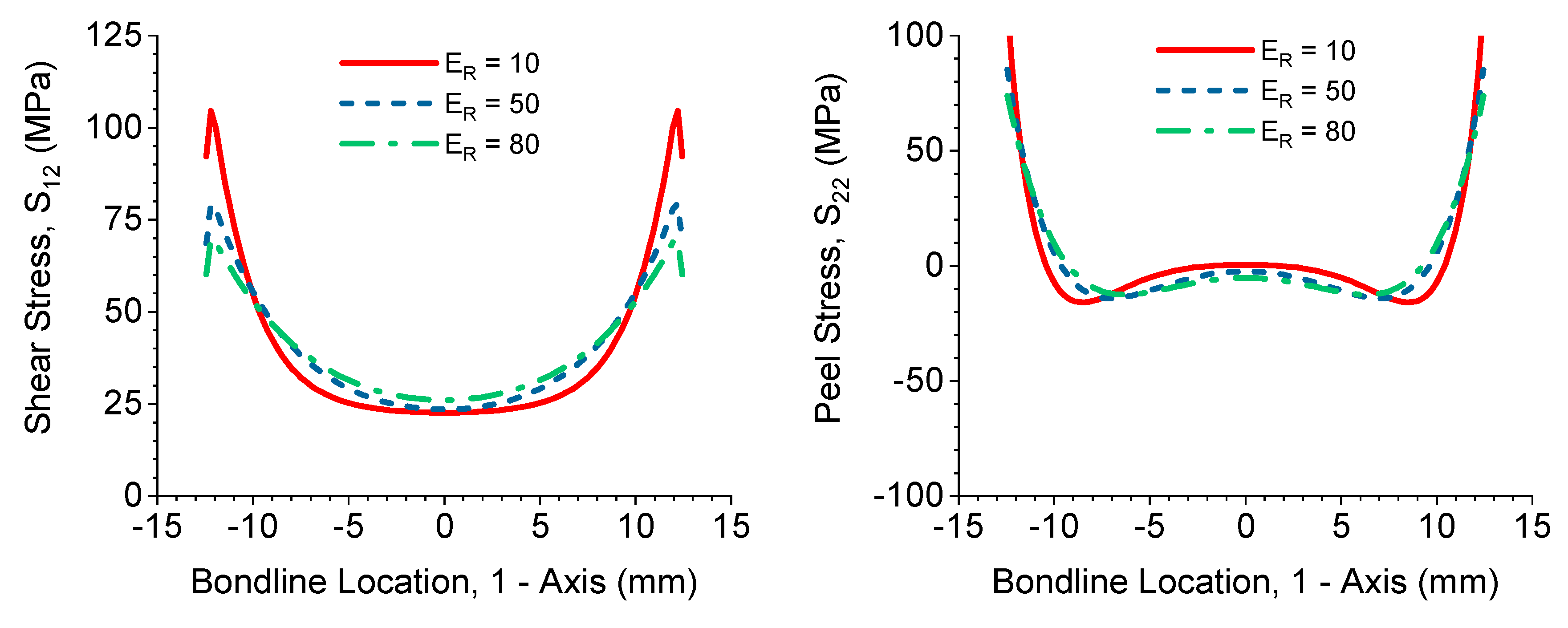
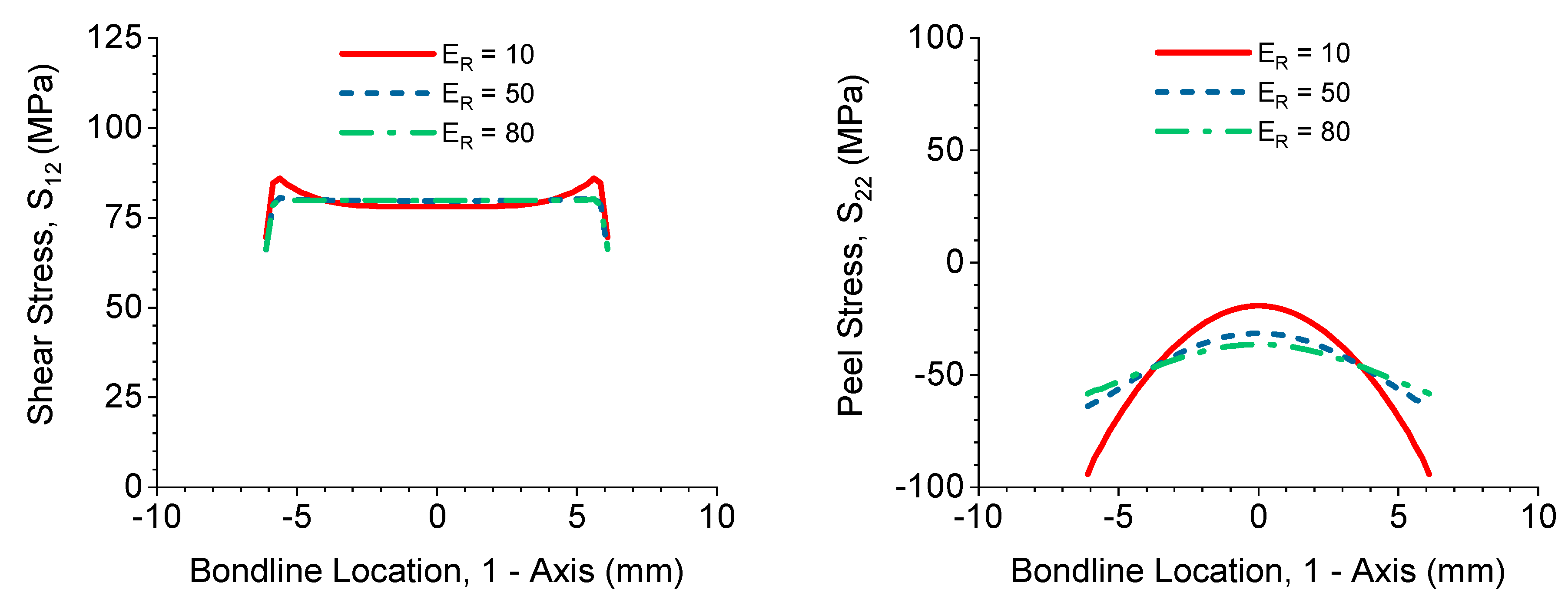
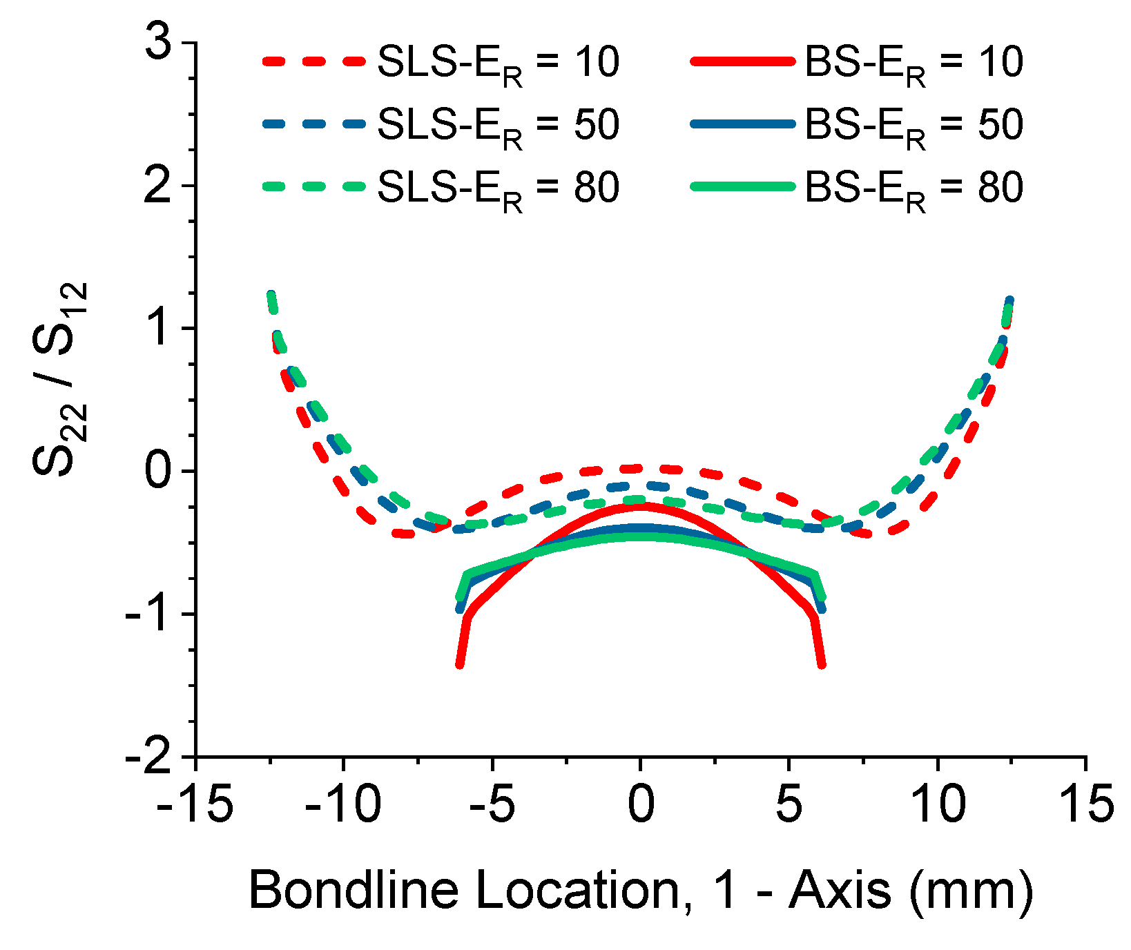
5.1. Stress Analysis
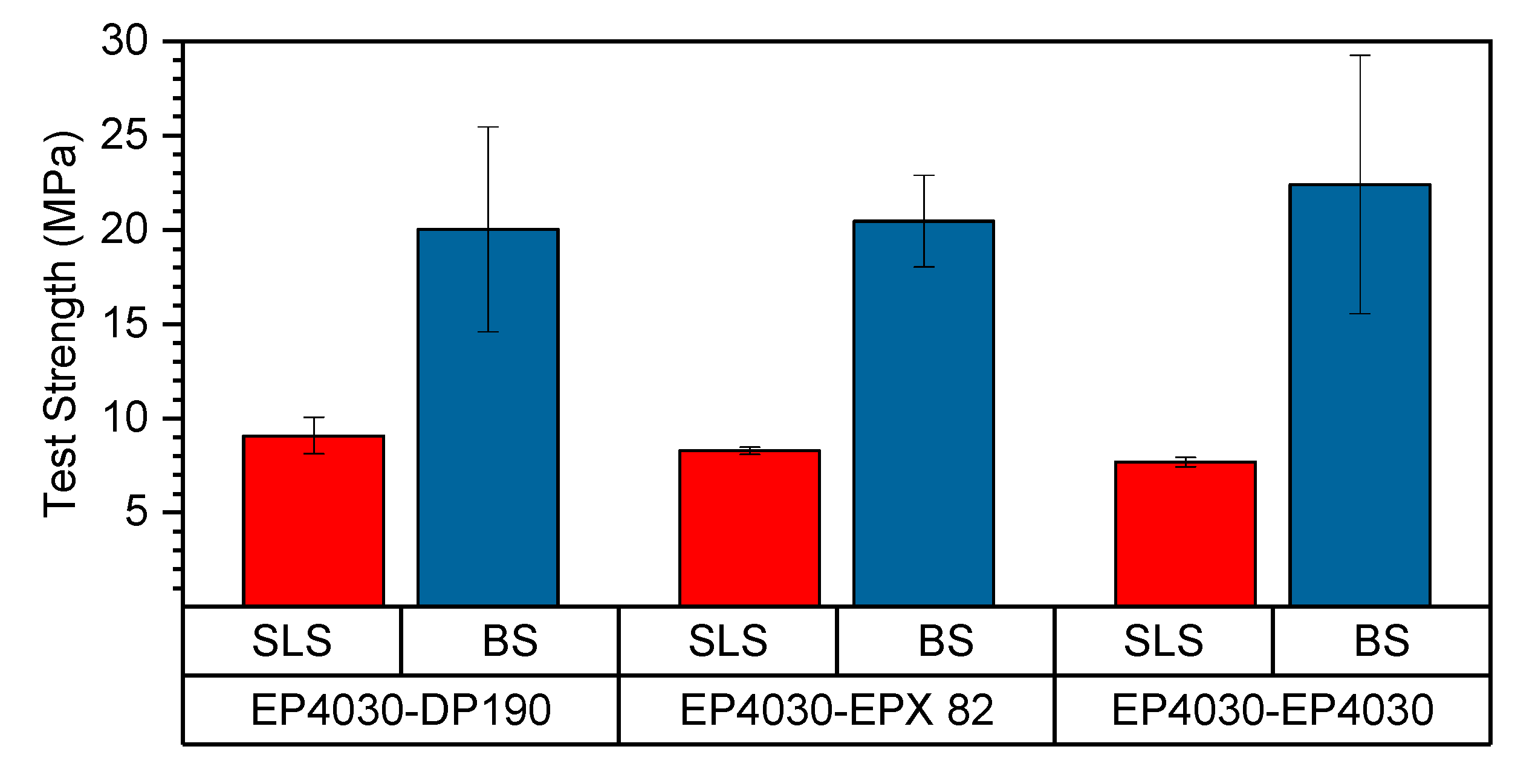
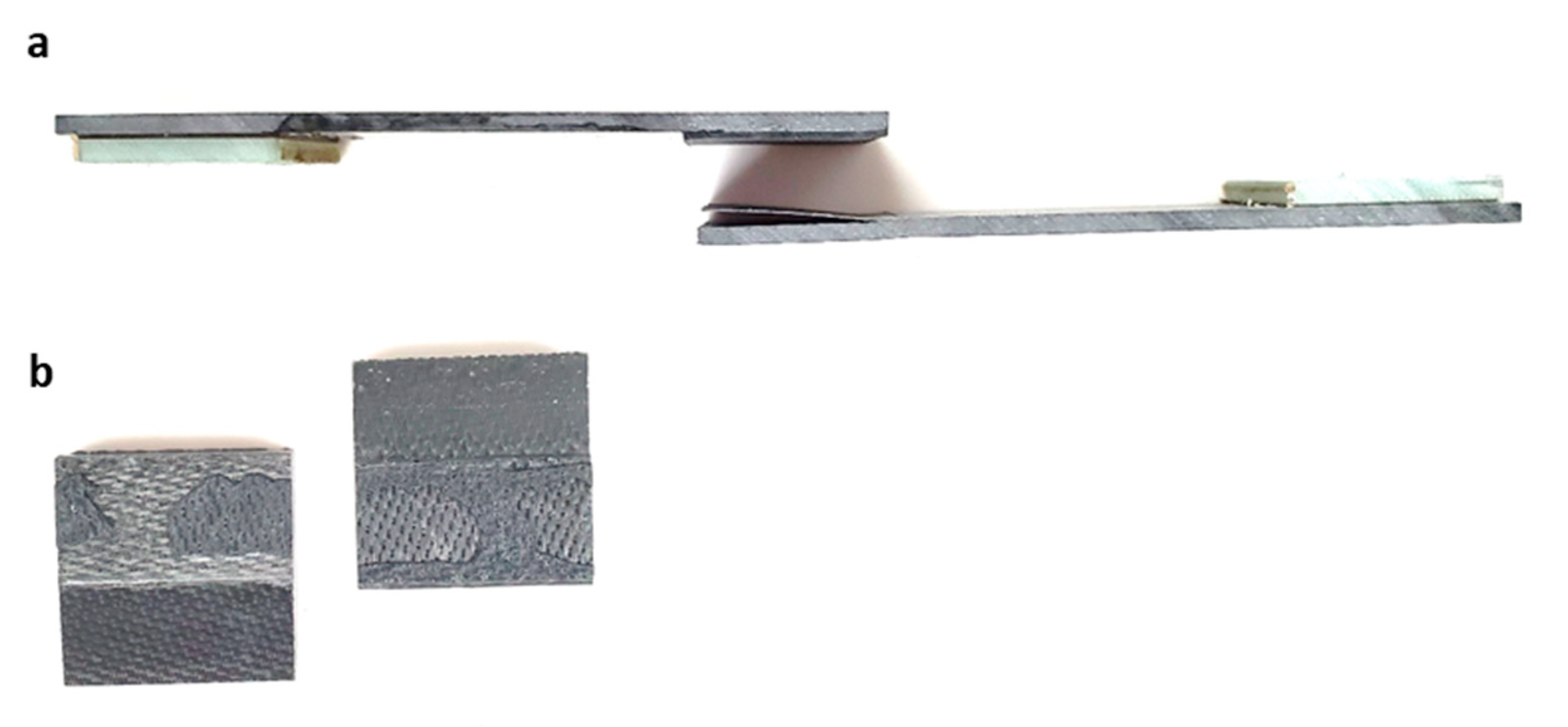
5.2. Shear Testing
6. Discussion
Author Contributions
Funding
Institutional Review Board Statement
Informed Consent Statement
Data Availability Statement
Conflicts of Interest
References
- Zhou, W.; Ai, S.; Chen, M.; Zhang, R.; He, R.; Pei, Y.; Fang, D. Preparation and thermodynamic analysis of the porous ZrO2/(ZrO2+Ni) functionally graded bolted joint. Compos. Part B Eng. 2015, 82, 13–22. [Google Scholar] [CrossRef]
- Zhou, W.; Zhang, R.; Ai, S.; He, R.; Pei, Y.; Fang, D. Load distribution in threads of porous metal-ceramic functionally graded composite joints subjected to thermomechanical loading. Compos. Struct. 2015, 134, 680–688. [Google Scholar] [CrossRef] [Green Version]
- Jones, R.M. Design of Composite Structures; Bull Ridge Publishing: Blacksburg, VA, USA, 2015. [Google Scholar]
- Herzberg, E.F.; Chan, T.K.; Guo, S.; Morris, A.K.; Stevenson, A.; Stroh, R.F. Estimated Impact of Corrosion on Cost and Availability of DoD Weapon Systems—FY18 Update; LMI: Tysons, VA, USA, 2018. [Google Scholar]
- Koch, G.; Varney, J.; Thompson, N.; Moghissi, O.; Gould, M.; Payer, J. International Measures of Prevention, Application, and Economics of Corrosion Technologies Study; NACE International: Houston, TX, USA, 2016. [Google Scholar]
- Pocius, A.V. Adhesion and Adhesives Technology: An Introduction, 3rd ed.; Carl Hanser: Munich, Germany, 2012. [Google Scholar]
- Da Silva, L.F.; Carbas, R.J.C.; Critchlow, G.W.; Figueiredo, M.A.V.; Brown, K. Effect of material, geometry, surface treatment and environment on the shear strength of single lap joints. Int. J. Adhes. Adhes. 2009, 29, 621–632. [Google Scholar]
- Cognard, J.Y.; Créac’Hcadec, R.; Maurice, J. Numerical analysis of the stress distribution in single-lap shear tests under elastic assumption—application to the optimisation of the mechanical behaviour. Int. J. Adhes. Adhes. 2011, 31, 715–724. [Google Scholar] [CrossRef]
- Adams, R.D.; Comyn, J.; Wake, W.C. Structural Adhesive Joints in Engineering, 2nd ed.; Chapman & Hall: London, UK, 1997. [Google Scholar]
- Matthews, F.L.; Kilty, P.F.; Godwin, E.W. A review of the strength of joints in fibre-reinforced plastics Part 2. Adhesively bonded joints. Composites 1982, 13, 29–37. [Google Scholar] [CrossRef]
- Adams, R.D. Strength predictions for lap joints, especially with composite adherends: A review. J. Adhes. 1989, 30, 219–242. [Google Scholar] [CrossRef]
- Banea, M.D.; da Silva, L.F.M. Adhesively bonded joints in composite materials: An overview. Proc. Inst. Mech. Eng. Part L J. Mater. Des. Appl. 2009, 223, 1–18. [Google Scholar] [CrossRef]
- ASTM International. ASTM D5856 Standard Test Method for Lap Shear Adhesion for Fiber Reinforced Plastic (FRP) Bonding; ASTM International: West Conshohocken, PA, USA, 2014. [Google Scholar]
- ASTM International. ASTM D4501 Standard Test Method for Shear Strength of Adhesive Bonds Between Rigid Substrates by the Block-Shear Method; ASTM International: West Conshohocken, PA, USA, 2014. [Google Scholar]
- Goland, M.; Reissner, E. The stresses in cemented joints. J. Appl. Mech. 1944, 11, A17–A27. [Google Scholar]
- Hart-Smith, L.J. Adhesive Bonded Single Lap Joints, Contractor Report 112236; NASA: Washington, DC, USA, 1973.
- Reddy, J.N. Theory and Analysis of Elastic Plates and Shells, 2nd ed.; CRC Press: Boca Raton, FL, USA, 2007. [Google Scholar]
- Oplinger, D.W. Effects of adherend deflections in single lap joints. Int. J. Solid Struct. 1994, 31, 2565–2587. [Google Scholar] [CrossRef]
- Li, G.; Lee-Sullivan, P. Re-visiting the beam models for adhesively bonded single-lap joints part 1: Comparison of bending moment predictions. Can. Aeronaut. Space J. 2006, 52, 149. [Google Scholar] [CrossRef]
- Mitsubishi Chemical Carbon Fiber and Composites. 4030 Data Sheet; Mitsubishi Chemical Carbon Fiber and Composites: Irvine, CA, USA, 2017. [Google Scholar]
- Mitsubishi Chemical Carbon Fiber and Composites. 301 Data Sheet; Mitsubishi Chemical Carbon Fiber and Composites: Irvine, CA, USA, 2016. [Google Scholar]
- 3M Industrial Adhesives and Tapes Division. 3M Scotch-Weld Epoxy Adhesives DP190 Data Sheet; 3M Industrial Adhesives and Tapes Division: St. Paul, MN, USA, 2010. [Google Scholar]
- EPX 82 Technical Data Sheet; 107172 rev. A.; Carbon: Redwood, CA, USA, 2018.
- Austermann, J.; Redmann, A.; Dahmen, V.; Quintanilla, A.; Mecham, S.J.; Osswald, T.A. Fiber-reinforced composite sandwich structures by co-curing with additive manufactured epoxy lattices. J. Comput. Sci. 2019, 3, 53. [Google Scholar] [CrossRef] [Green Version]
- Dahmen, V.; Redmann, A.; Austermann, J.; Quintanilla, A.; Mecham, S.J.; Osswald, T.A. Fabrication of hybrid composite T-joints by co-curing with 3D printed dual cure epoxy. Compos. Part B Eng. 2020, 183, 107728. [Google Scholar] [CrossRef]


| Material Properties | Value | Unit |
|---|---|---|
| NB4030-D [20] | ||
| Tensile Modulus | 32.8 | GPa |
| Tensile Strength | 2370 | MPa |
| Elongation at break | - | % |
| Glass Transition Temperature | 130 | °C |
| Fiber Volume Content | 60 | % |
| DP190 [22] | ||
| Tensile Modulus | - | GPa |
| Tensile Strength | 24.13 | MPa |
| Elongation at Break | 30 | % |
| Glass Transition Temperature | 20 | °C |
| EPX 82 [23] | ||
| Tensile Modulus | 2.8 | GPa |
| Tensile Strength | 82 | MPa |
| Elongation at break | 5.9 | % |
| Glass Transition Temperature | 150–155 | °C |
Publisher’s Note: MDPI stays neutral with regard to jurisdictional claims in published maps and institutional affiliations. |
© 2021 by the authors. Licensee MDPI, Basel, Switzerland. This article is an open access article distributed under the terms and conditions of the Creative Commons Attribution (CC BY) license (http://creativecommons.org/licenses/by/4.0/).
Share and Cite
Redmann, A.; Damodaran, V.; Tischer, F.; Prabhakar, P.; Osswald, T.A. Evaluation of Single-Lap and Block Shear Test Methods in Adhesively Bonded Composite Joints. J. Compos. Sci. 2021, 5, 27. https://0-doi-org.brum.beds.ac.uk/10.3390/jcs5010027
Redmann A, Damodaran V, Tischer F, Prabhakar P, Osswald TA. Evaluation of Single-Lap and Block Shear Test Methods in Adhesively Bonded Composite Joints. Journal of Composites Science. 2021; 5(1):27. https://0-doi-org.brum.beds.ac.uk/10.3390/jcs5010027
Chicago/Turabian StyleRedmann, Alec, Vinay Damodaran, Felix Tischer, Pavana Prabhakar, and Tim A. Osswald. 2021. "Evaluation of Single-Lap and Block Shear Test Methods in Adhesively Bonded Composite Joints" Journal of Composites Science 5, no. 1: 27. https://0-doi-org.brum.beds.ac.uk/10.3390/jcs5010027