Article

Investigating the Effect of Interface Morphology in Adhesively Bonded Composite Wavy-Lap Joints

1
Department of Mechanical and Aerospace Engineering, University of Strathclyde, 75 Montrose Street, Glasgow G1 1XJ, UK
2
Department of Engineering Design and Mathematics, University of the West of England (UWE), Bristol BS16 1QY, UK
3
Department of Mechanical Engineering, University of Tabriz, Tabriz 5166614766, Iran
4
Randon Center of Technology—Estrada Arziro Galafassi, s/no, Farroupilha 95180-000, Brazil
5
PPGE3M, Federal University of Rio Grande do Sul, Osvaldo Aranha 99, Porto Alegre 90035-190, Brazil
6
School of Engineering, University of Glasgow, Glasgow G12 8QQ, UK
*
Author to whom correspondence should be addressed.
Submission received: 31 December 2020 / Revised: 14 January 2021 / Accepted: 14 January 2021 / Published: 17 January 2021
(This article belongs to the Special Issue Feature Papers in Journal of Composites Science in 2021)

Abstract

:
Joints and interfaces are one of the key aspects of the design and production of composite structures. This paper investigates the effect of adhesive–adherend interface morphology on the mechanical behavior of wavy-lap joints with the aim to improve the mechanical performance. Intentional deviation from a flat joint plane was introduced in different bond angles (0°, 60°, 90° and 120°) and the joints were subjected to a quasi-static tensile load. Comparisons were made regarding the mechanical behavior of the conventional flat joint and the wavy joints. The visible failure modes that occurred within each of the joint configurations was also highlighted and explained. Load vs. displacement graphs were produced and compared, as well as the failure modes discussed both visually and qualitatively. It was observed that distinct interface morphologies result in variation in the load–displacement curve and damage types. The wavy-lap joints experience a considerably higher displacement due to the additional bending in the joint area, and the initial damage starts occurring at a higher displacement. However, the load level had its maximum value for the single-lap joints. Our findings provide insight for the development of different interface morphology angle variation to optimize the joints behavior, which is widely observed in some biological systems to improve their performance.

1. Introduction

A composite material is engineered by combining two or more constituent materials which have significantly different physical properties, in order to produce a resulting material which displays noticeably enhanced features. Composite materials have played a key role in developing the various industries and sectors due to the superior mechanical properties they withhold, as well as their significant weight saving ability compared to metallic structures. The use of composites as an alternative to existing metallic structures within these industries has occurred due to their ability to possess high energy absorption rates, while maintaining their structural role [1]. They also possess relatively high stiffness and tensile strengths as well as excellent corrosion resistance properties when compared to conventional materials such as metals [2].
Joints and interfaces are one of the key aspects of the design and production of composite structures [3]. Composite structures are assembled through a network of connections. These connections usually consist of bolts/rivets. However, as a result, the load-bearing fibers are damaged, and high local stresses are introduced into these weakened regions [4]. Adhesive bonding is an alternative joining process in which an adhesive is placed between adherend surfaces and then left to solidify−producing the adhesive bond [5]. Kim et al. [6] argued that the method of mechanical fastening may cause problems in stress concentration and would also unnecessarily increase the weight of the structures. They also concluded that adhesively bonded joints are more efficient than mechanical fastening as the load transfer between composite parts is more uniformly performed through a larger area. This was reinforced by Khan et al. [7] who also argued that mechanically fastened joints heavily increase the weight of structures and represent a non-uniform distribution of load compared to adhesively bonded joints. Silva et al. [8] provided further advantages of adhesive bonding, stating that they offer reduction of stress concentrations, good response to fatigue stresses and that their increased ability to bond dissimilar materials as well as reinforcing the earlier arguments that they produce lightweight structures. They also however provided some limitations that occur due to adhesive bonding. These include the difficulty of disassembly (due to the fixed bond), high cure times and limited temperature and humidity conditions.
Budhe et al. [9] reported that bonding methods, surface preparation, adhesive thickness, overlap length, stacking sequence, ply angle, fillet, etc. affect the performance of adhesively bonded joints depending on many parameters. These conclusions were reinforced by Silva et al. [8], who also reported that several factors such as the type of adhesive used, the material of the adherends and the joint configuration affect the bond quality. In addition, dimensional factors such as the overlap length and the thickness of both the adhesive and the adherends were also stated to play a role in the behavior of the joints.
Adhesive properties can be a limiting factor in bonded joints [10,11,12]; thus, efforts have been made to develop better adhesives [5,13,14]. Surface treatment was also used to modify the bond quality by improving the micro-topography of the adherend surfaces [15,16]. Changing the joint geometry (e.g., adherend scarfing or tapering, adhesive fillets or foam spacers) was also used for improving bond properties [17,18,19]. For instance, bonded wavy-lap joints show a higher strength than a flat-lap joint [20,21,22].
A major drawback of single-lap joints is the presence of the offset within the two sheets, which produces a misalignment that is coupled with a bending moment in the joint [23,24]. This bending moment intensifies the local peel and shear stresses at both ends of the lapped region. This in turn reduces the efficiency of the load transfer to an undesirable figure.
The original wavy-lap joint design was presented by Zeng and Sun [20], who concluded that the strength of their joint was significantly higher than that of a conventional single-lap joint. They also suggested that an even higher strength could be obtained after further design optimization. Avila and Bueno [21] modified the previously investigated wavy-lap joint, which was then tested under similar conditions. They also stated that their improvements led to a 41% increase in the maximum load carried by the wavy lap-joint, as opposed to a standard single-lap joint. These conclusions were reinforced in further studies carried out by Ayatollahi et al. [25], who tested aluminum adherends with wavy interfaces under quasi-static and fatigue loading conditions. Their experimental results showed that the non-flat joints were noticeably stronger than the conventional flat joints. This provides a feasible basis for the study in this paper, which explores the performance of modified wavy-lap joints by employing varied bond angles for the adhesive bonded composite joints. Here, we introduce extreme morphological changes near the edges of bonded lap joints. This paper presents the fabricating and testing of these wavy-lap joints with different interface morphologies, along with the associated failure modes and load–displacement behavior.

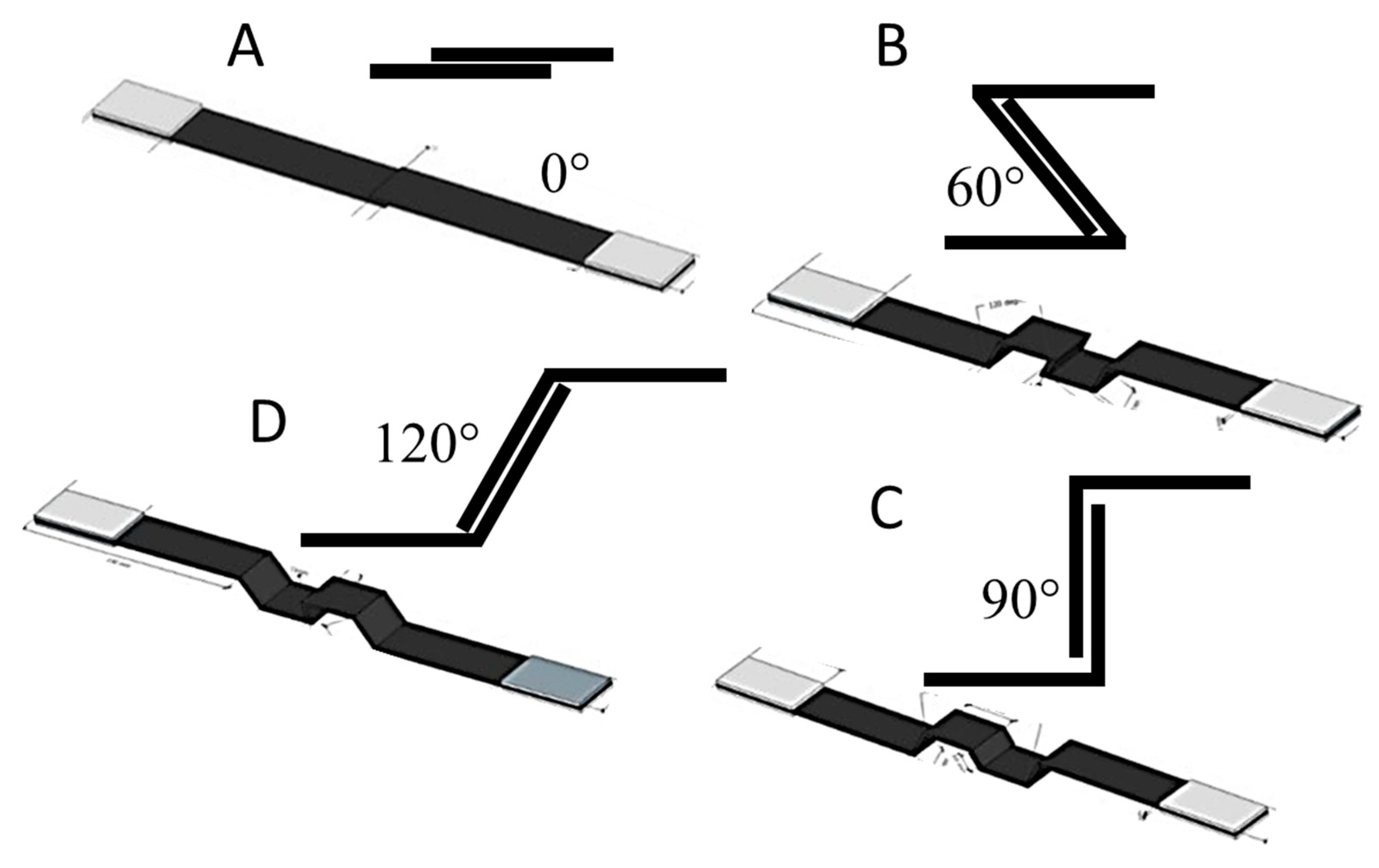
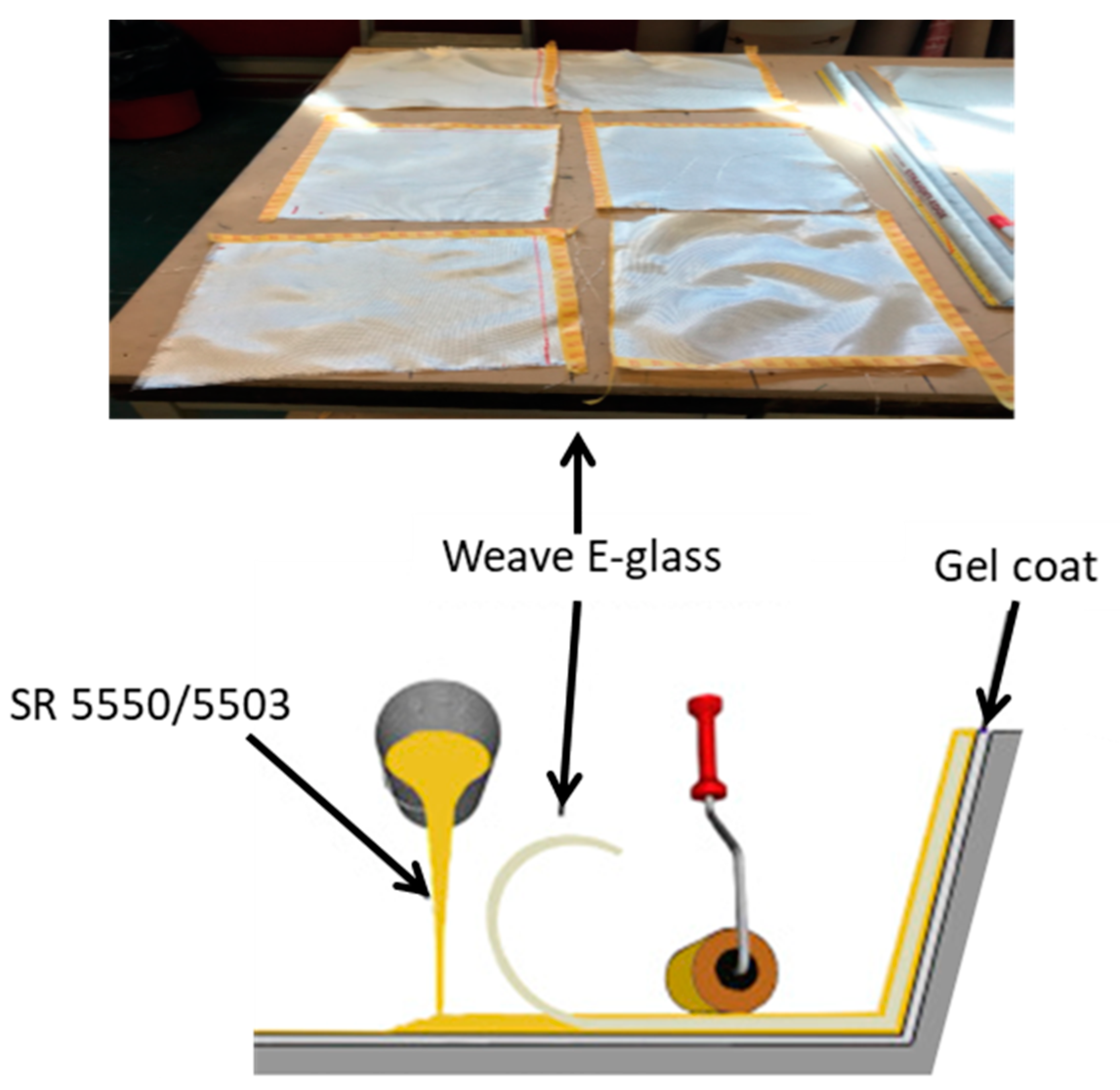
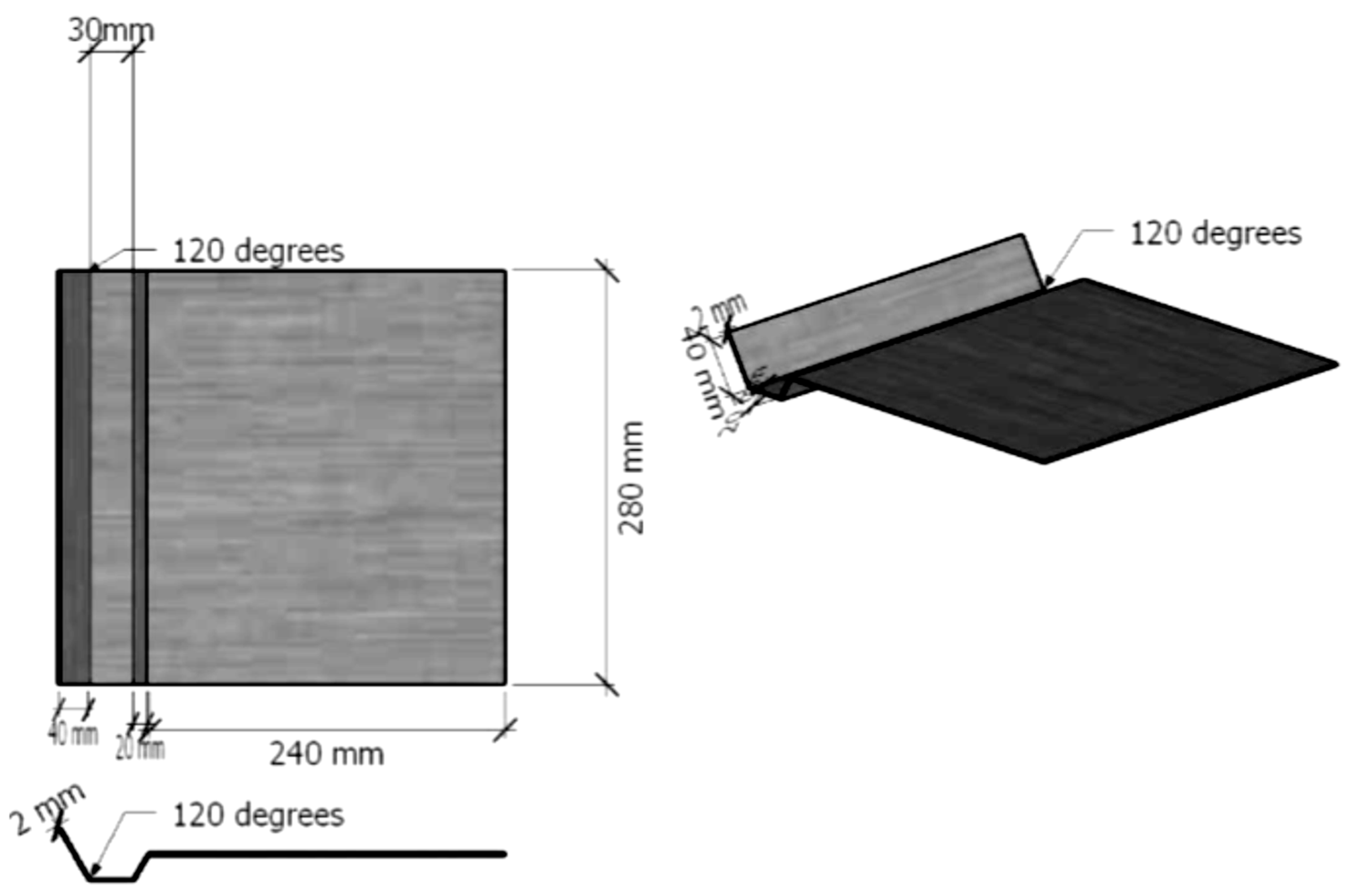
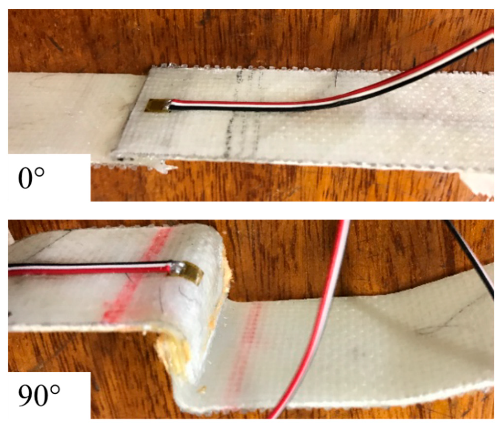
2. Materials and Manufacturing

To gain a full understanding of the influence of the wavy-lap joint configurations, four different joint geometries were explored. They were conventional single-lap joints and wavy-lap joints with three different interlocking angles 60°, 90° and 120°, as shown in Figure 1.
Composite plates (375 × 280 mm2) made of 6 layers of 290 gsm woven glass cloth (0°/90°) with consolidated thickness of 1.98 mm (0.33 mm for each layer) available from Easy Composites were stacked together as a symmetrical and balanced layup, [0/90, ±45, 0/90]s, using a wet hand layup system (see Figure 2). Sicomin SR 5550 paired with the hardener Sicomin 5503 was used as the matrix. The resin was applied to the fibrous layers in a stippling motion to ensure an even distribution of resin has been applied throughout. Focus was placed on the kink produced by an aluminum mold, to shape the samples in the specified configurations (see Figure 3 for an example) and ensuring that they get the flat surface and the bond angles. The layers were applied in a well-ventilated area to ensure that no dust or other loose particles could attach to the FRP. The vacuum was then applied for a total of 2 h, before the through bag connector was removed. A standard composite vacuum pump was used and was available within the workshops provided. The vacuum bag was left to set for 14 h, to ensure all the resin had dried and mixed with the fibers.
Once each sheet was fabricated, the end tabs and the sheets were adhered together using Araldite® Standard 2-part adhesive. Once a thin layer (approximately 0.05–0.1 mm thick) of the adhesive was applied to the bond area, the joints were clamped for 24 h to ensure that they held together and so that the adhesive could stick to both adherends sufficiently. The overlap lengths of the adhesively bonded joints were kept constant at 10 mm for all joints. The composite plates were then cut down into strips using an electric band saw. Extra precaution was taken at this stage to avoid cutting-induced damage on the edges of the samples. Figure 4 and Figure 5 show the test samples with two attached stain gauges to measure the strain level on the joint area and the far field strain.

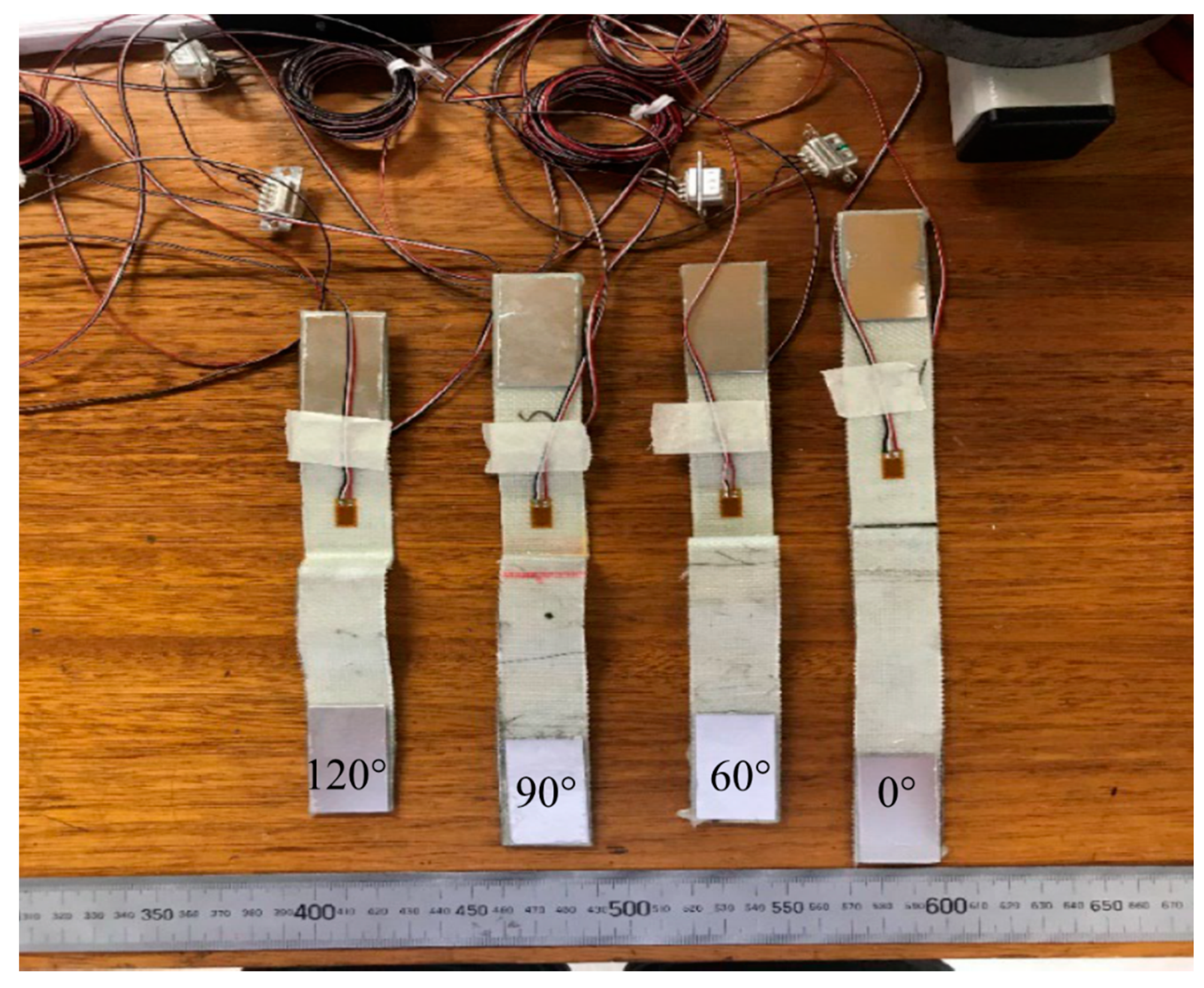
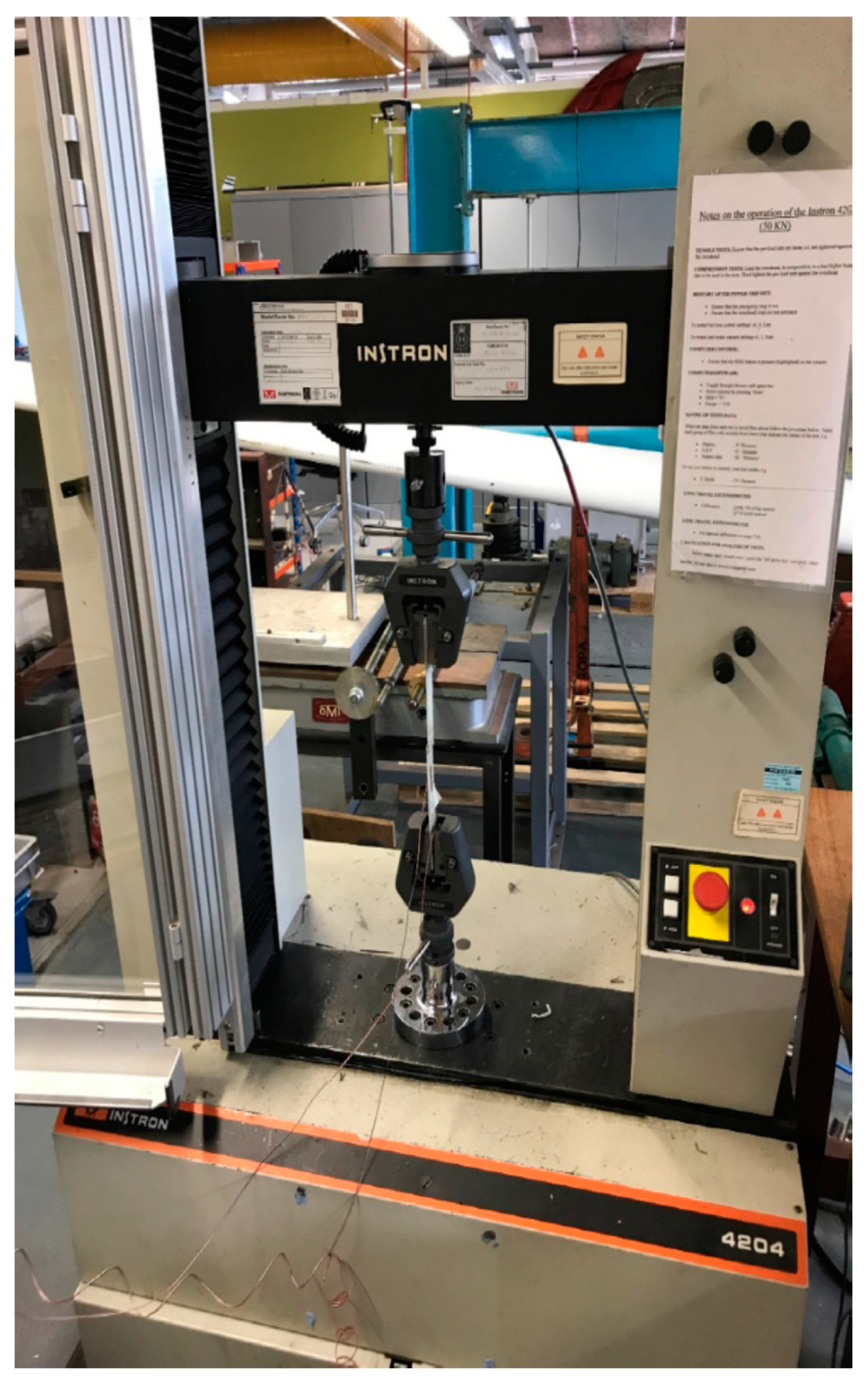
3. Mechanical Testing

Instron 4204 tensile test machine with a 10KN load cell was used for the experiments. The strain readings were measured using the Strain Smart 9000 Data Acquisition Software, which was attached to the test specimen via connecting soldered plugs. The tensile machine uses wedge grips which are specific for tensile testing because, as the load increases, the grip gets tighter. The 2 mm/min displacement rate was chosen to conduct a quasi-static loading condition. The width and thickness of the test specimen was recorded in the Instron machine before the run was initiated. While the run was being performed, the machine was recording the displacement values, as well as the load applied, tensile stresses and the strain readings (for the gauged samples). Figure 6 shows the Instron testing machine, with the test sample clamped in place performing a tensile loading test.

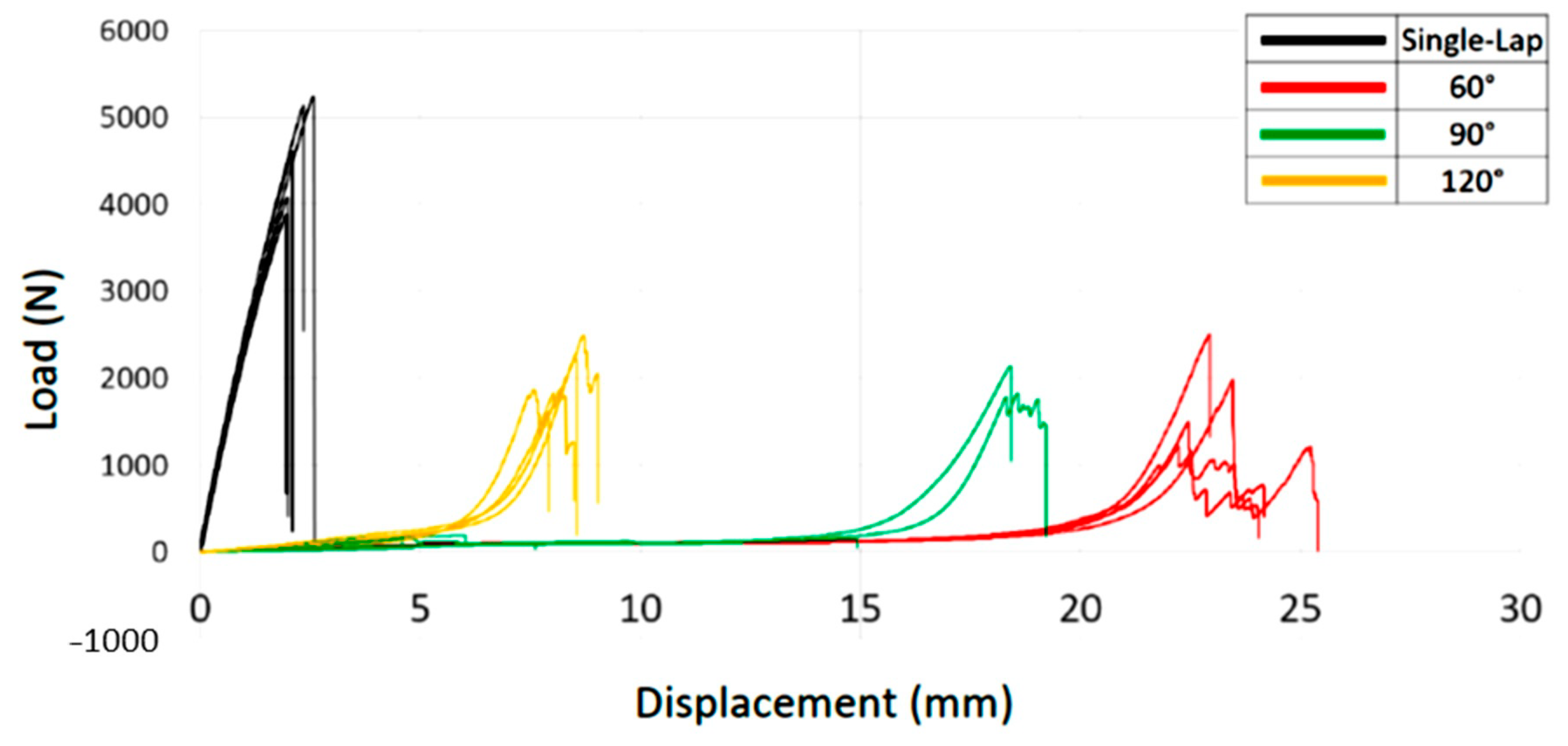
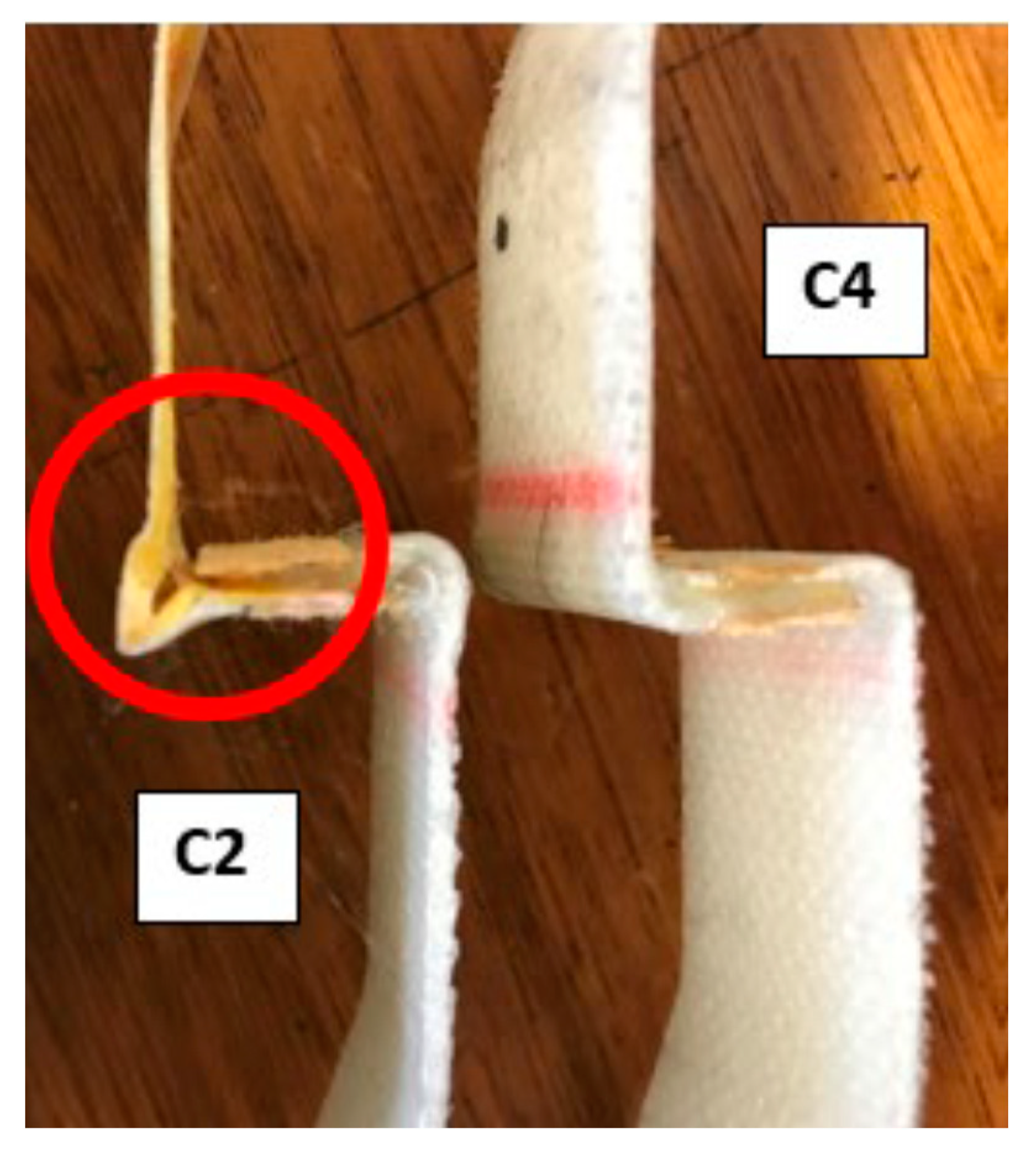
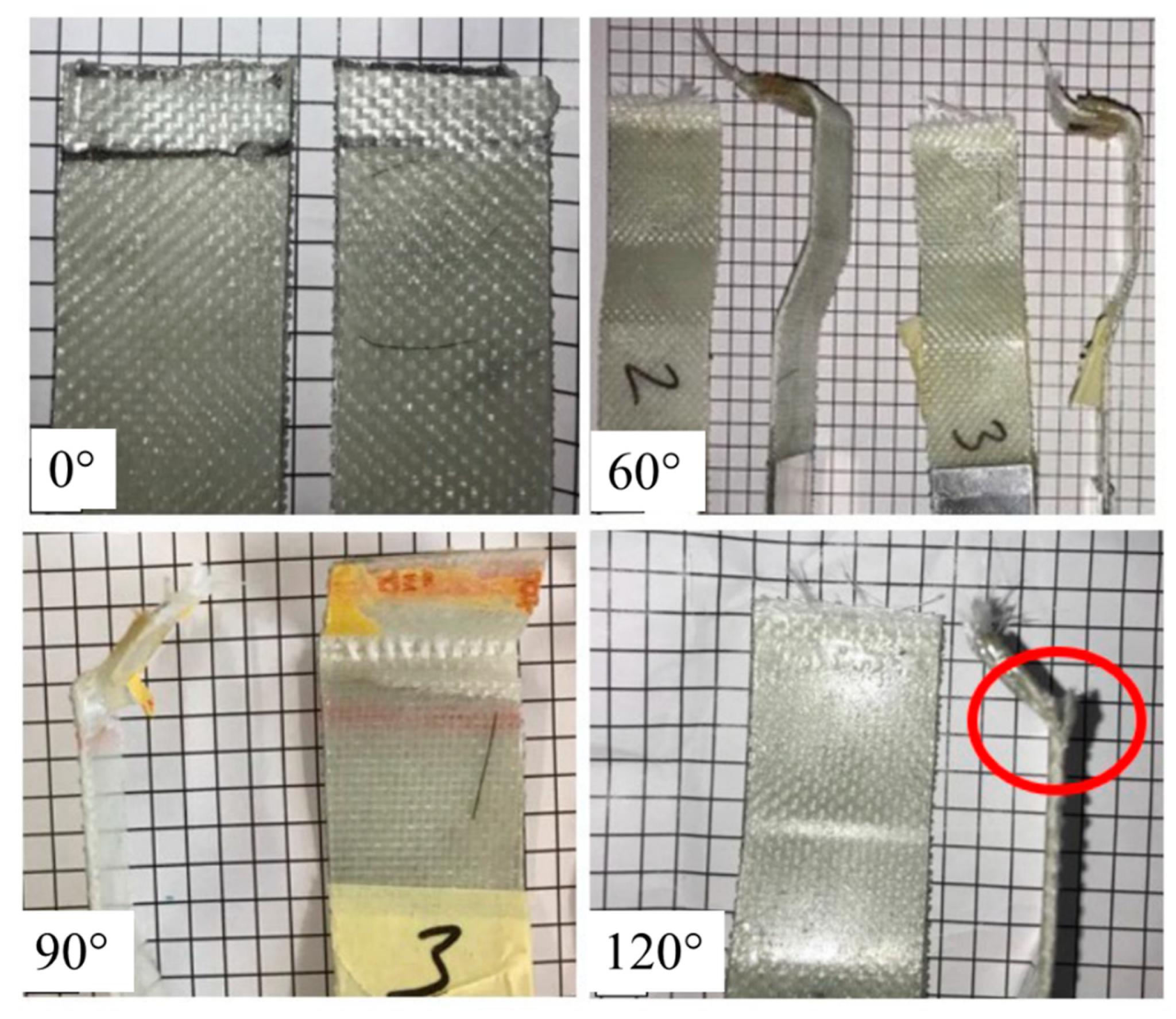
4. Results and Discussion

Figure 7 shows the load versus displacement curve for the four types of investigated samples. A good repeatability can be observed for the single-lap, 60° and 120° configurations. This however cannot be said for the 90° samples. The single-lap joints show a significantly larger peak load in comparison to the joints with the modified geometries. The highest load recorded was 5190.5 N, experienced by the single-lap joints. The next highest peak loads were recorded within the joints with both 60° and 120° bond angles, at 2475.3 and 2430.9 N, respectively. The lowest accepted peak load was recorded at 1150.5 N, which occurred within the 60° bonded joints. The wavy-lap joints experience a considerably higher displacement due to the additional bending in the joint area. The single-lap joints show the lowest displacement values, ranging from 1.9 to 2.6 mm. The highest displacement values were recorded within the joints with 60° bond angles, ranging from 22.8 to 25.4 mm. The 90° angled joints showed irregular behavior patterns. The smallest recorded displacement for these joints was 4.6 mm in comparison to the largest recording of 19.2 mm. The specimens with 120° bond angles produced the second lowest displacement values, ranging from 7.9 to 9.1 mm. Four out of six test samples with the 90° joint configuration in Figure 8 failed noticeably earlier than the remaining two samples, at a load of around 100–150 N. This is a significantly unexpected result. The reason for this occurring is due to a failure in the adhesive, which was caused by a manufacturing defect: the tape running through the joint caused weak adhesion. An example of such defect is shown in Figure 7, comparing defective and healthy joints. The two remaining joints with no defects showed a total load capacity of around 1700 N.
Table 1 provides a summary of max far filed stress and max strain on the joints. The single lap joints showed the highest max stress value of 119 MPa. The lowest stress was recorded for 120° joints, which was 53 MPa. The single lap joints had a max strain on the joint value of 1899 με; however the other three joint configurations all had negative values of −3099, −4193 and −4397 με for the 60°, 90° and 120° samples, respectively. The negative values indicate that the joints were under compression when being tested. The positive strain recording for the single-lap joint suggests that it behaved as expected.
The development of the ASTM D5573 standard [26] states that there are seven standardized modes of failure that can be observed within adhesively bonded fiber-reinforced plastic joints. The seven types of failure that are described are outlined in Table 2. To gain a better understanding of the behaviors of the joints when being tested, the failure mechanisms that occurred within each joint configuration were explored and described. Figure 9 shows images of the failed joints. The single-lap joints showed uniform failure within the adhesive, leading to the conclusion of cohesive failure. Identical conclusions were made by Adin [27], who found that, for single-lap joints, cohesive failure occurred starting from the edges. There were also signs of the presence of light fiber tear failure. The failure was brittle (catastrophic). There was no bending that took place, because the joints were straight with a small overlap region. Similar conclusions were made by Li et al. [28], who showed that small overlap lengths cause failure within the adhesive. This would explain the low displacement values observed in Figure 7.
In the 60° joints, failure modes were almost uniform for all samples. There was excessive stock-break failure present, as well as fiber-tear failure. The stock-break failure matched with the high displacement rates recorded earlier, showing that there was significant bending that occurred during the tensile test. The test specimens with 90° bond angle failed almost identically due to a mixture of thin-layer cohesive failure and fiber tear failure. Ductile failure was present due to the bending that occurred during the test. As explained above, the specimens with the 90° bond angles showed excessive adhesive failure due to poor manufacture quality. This observation is concurrent with the low load vs. displacement values obtained in Figure 7. The two specimens that performed correctly, however, showed similar failure types as those of 60° and 120° joints, as shown in Figure 9. The failure modes that occurred within the joints with 120° were concurrent with the specimens with the 60° joints. Fiber-tear failure was present along with stock-break failure. The highlighted region in Figure 9 and higher displacements of the wavy joints in Figure 7 show the significant bending displacement that was present before the bond failure.

5. Conclusions

This study experimentally investigated the effects of extreme adhesive–adherend interface morphologies (0°, 60°, 90°, and 120° bond angles) on the mechanical behavior of wavy-lap joints. From the experimental results, the single-lap joints that were flat experienced the highest stiffness and load values, while the 60°, 90° and 120° bond angles reduced the maximum load and increased the maximum displacement compared to the single-lap joint. The higher displacement experienced by the modified joints is believed to be due to elastic bending displacement before the damage initiation. The interface morphology modifications changed the type of failure compared with the single-lap joint as well. This can be attributed to different stress distribution near the bond for the investigated samples that resulted in a complicated failure for the modified joints. The results show significant dependance of the joints mechanical and failure behavior on the applied modifications, suggesting new avenues for tailoring the performance of the joints based on the design requirements to meet specific requirements such as higher displacement, higher load or a gradual failure.

Author Contributions

Conceptualization, M.F. and S.A.; methodology, S.A.; investigation, S.A. and M.F.; resources, M.F.; writing—original draft preparation, R.A., S.F., J.B., M.F. and F.V.d.C.; writing—review and editing, J.B., M.F., F.V.d.C. and S.F.; supervision, M.F.; project administration, S.A.; and funding acquisition, M.F. All authors have read and agreed to the published version of the manuscript.

Funding

This work was funded under the UK Engineering and Physical Sciences Research Council (EPSRC) Programme Grant EP/V009451/1 on Next generation of high-performance impact resistant composites with visibility of damage. The data necessary to support the conclusions are included in the paper.

Conflicts of Interest

The authors declare no conflict of interest.

References

  1. Meredith, J.; Bilson, E.; Powe, R.; Collings, E.; Kirwan, K. A performance versus cost analysis of prepreg carbon fibre epoxy energy absorption structures. Compos. Struct. 2015, 124, 206–213. [Google Scholar] [CrossRef] [Green Version]
  2. Kumar, S.; Sridhar, I.; Sivashanker, S.; Osiyemi, S.; Bag, A. Tensile failure of adhesively bonded CFRP composite scarf joints. Mater. Sci. Eng. B 2006, 132, 113–120. [Google Scholar] [CrossRef]
  3. Burns, L.; Mouritz, A.; Pook, D.; Feih, S. Bio-inspired design of aerospace composite joints for improved damage tolerance. Compos. Struct. 2012, 94, 995–1004. [Google Scholar] [CrossRef]
  4. Pramanik, A.; Basak, A.; Dong, Y.; Sarker, P.; Uddin, M.; Littlefair, G.; Dixit, A.; Chattopadhyaya, S. Joining of carbon fibre reinforced polymer (CFRP) composites and aluminium alloys—A review. Compos. Part A: Appl. Sci. Manuf. 2017, 101, 1–29. [Google Scholar] [CrossRef] [Green Version]
  5. Banea, M.D.; Da Silva, L.F.M. Adhesively bonded joints in composite materials: An overview. Proc. Inst. Mech. Eng. Part L J. Mater. Des. Appl. 2009, 223, 1–18. [Google Scholar] [CrossRef]
  6. Kim, K.-S.; Yoo, J.-S.; Yi, Y.-M.; Kim, C.-G. Failure mode and strength of uni-directional composite single lap bonded joints with different bonding methods. Compos. Struct. 2006, 72, 477–485. [Google Scholar] [CrossRef]
  7. Khan, M.; Aglietti, G.; Crocombe, A.; Viquerat, A.; Hamar, C. Development of design allowables for the design of composite bonded double-lap joints in aerospace applications. Int. J. Adhes. Adhes. 2018, 82, 221–232. [Google Scholar] [CrossRef] [Green Version]
  8. Silva, D.F.O.; Campilho, R.; Silva, F.J.G.; Carvalho, U.T.F. Application a direct/cohesive zone method for the evaluation of scarf adhesive joints. Appl. Adhes. Sci. 2018, 6, 13. [Google Scholar] [CrossRef] [Green Version]
  9. Budhe, S.; Banea, M.; De Barros, S.; Da Silva, L. An updated review of adhesively bonded joints in composite materials. Int. J. Adhes. Adhes. 2017, 72, 30–42. [Google Scholar] [CrossRef]
  10. Davis, M.; Bond, D. Principles and practices of adhesive bonded structural joints and repairs. Int. J. Adhes. Adhes. 1999, 19, 91–105. [Google Scholar] [CrossRef]
  11. Kinloch, A.J. Interfacial Fracture Mechanical Aspects of Adhesive Bonded Joints—A Review. J. Adhes. 1979, 10, 193–219. [Google Scholar] [CrossRef]
  12. Sheppard, A.; Kelly, D.; Tong, L. A damage zone model for the failure analysis of adhesively bonded joints. Int. J. Adhes. Adhes. 1998, 18, 385–400. [Google Scholar] [CrossRef]
  13. Ebnesajjad, S.; Landrock, A.H. Adhesives Technology Handbook; Elsevier BV: London, UK, 2015. [Google Scholar]
  14. Katsiropoulos, C.; Chamos, A.N.; Tserpes, K.I.; Pantelakis, S. Fracture toughness and shear behavior of composite bonded joints based on a novel aerospace adhesive. Compos. Part B Eng. 2012, 43, 240–248. [Google Scholar] [CrossRef]
  15. Kim, W.-S.; Yun, I.-H.; Lee, J.-J.; Jung, H.-T. Evaluation of mechanical interlock effect on adhesion strength of polymer–metal interfaces using micro-patterned surface topography. Int. J. Adhes. Adhes. 2010, 30, 408–417. [Google Scholar] [CrossRef]
  16. Molitor, P.; Barron, V.; Young, T. Surface treatment of titanium for adhesive bonding to polymer composites: A review. Int. J. Adhes. Adhes. 2001, 21, 129–136. [Google Scholar] [CrossRef]
  17. Renton, W.J.; Vinson, J.R. The Efficient Design of Adhesive Bonded Joints. J. Adhes. 1975, 7, 175–193. [Google Scholar] [CrossRef]
  18. Da Silva, L.; Adams, R. Adhesive joints at high and low temperatures using similar and dissimilar adherends and dual adhesives. Int. J. Adhes. Adhes. 2007, 27, 216–226. [Google Scholar] [CrossRef]
  19. Akrami, R.; Fotouhi, S.; Fotouhi, M.; Bodaghi, M.; Clamp, J.; Bolouri, A. High-performance bio-inspired composite T-joints. Compos. Sci. Technol. 2019, 184, 107840. [Google Scholar] [CrossRef]
  20. Zeng, Q.-G.; Sun, C.T. Novel Design of a Bonded Lap Joint. AIAA J. 2001, 39, 1991–1996. [Google Scholar] [CrossRef]
  21. Ávila, A.F.; Bueno, P.D.O. Stress analysis on a wavy-lap bonded joint for composites. Int. J. Adhes. Adhes. 2004, 24, 407–414. [Google Scholar] [CrossRef]
  22. Ashrafi, M.; Ajdari, A.; Rahbar, N.; Papadopoulos, J.; Nayeb-Hashemi, H.; Vaziri, A. Adhesively bonded single lap joints with non-flat interfaces. Int. J. Adhes. Adhes. 2012, 32, 46–52. [Google Scholar] [CrossRef]
  23. Her, S.-C. Stress analysis of adhesively-bonded lap joints. Compos. Struct. 1999, 47, 673–678. [Google Scholar] [CrossRef]
  24. Boss, J.; Ganesh, V.; Lim, C. Modulus grading versus geometrical grading of composite adherends in single-lap bonded joints. Compos. Struct. 2003, 62, 113–121. [Google Scholar] [CrossRef]
  25. Ayatollahi, M.; Samari, M.; Razavi, S.M.J.; Da Silva, L.F.M. Fatigue performance of adhesively bonded single lap joints with non-flat sinusoid interfaces. Fatigue Fract. Eng. Mater. Struct. 2017, 40, 1355–1363. [Google Scholar] [CrossRef]
  26. ASTM International. D5573-99 Standard Practice for Classifying Failure Mode in Fiber-Reinforced-Plastic (FRP); ASTM International: West Conshohocken, PA, USA, 2019. [Google Scholar]
  27. Adin, H. The effect of angle on the strain of scarf lap joints subjected to tensile loads. Appl. Math. Model. 2012, 36, 2858–2867. [Google Scholar] [CrossRef] [Green Version]
  28. Li, J.; Yan, Y.; Zhang, T.; Liang, Z. Experimental study of adhesively bonded CFRP joints subjected to tensile loads. Int. J. Adhes. Adhes. 2015, 57, 95–104. [Google Scholar] [CrossRef]
Figure 1. Schematic drawings of each of the different joint configurations: (A) single-lap joint; (B) 60° joint configuration; (C) 90° joint configuration; and (D) 120° joint configuration.
Jcs 05 00032 g001
Figure 2. Schematic of the fabrication process and image of the weave E-glass fiber textiles used for the fabrication of the composite panel.
Jcs 05 00032 g002
Figure 3. Schematic of an aluminum mold, with 2 mm thickness, for the 120° joint configuration.
Jcs 05 00032 g003
Figure 4. Test specimens with far-field strain gauges attached.
Jcs 05 00032 g004
Figure 5. Images from the test samples showing the location of the strain gauge used to record the max strain values for the 0° and 90° joints.
Jcs 05 00032 g005
Figure 6. Instron testing machine carrying out testing.
Jcs 05 00032 g006
Figure 7. Load vs. displacement graph for the investigated test samples.
Jcs 05 00032 g007
Figure 8. Comparison of a defective 90° joint (left) with a healthy 90° joint (right) showing no sign of defects.
Jcs 05 00032 g008
Figure 9. Images of the failures that occurred within each test specimen: single-lap joint 0°; 60° bond angle; 90° bond angle; and 120° bond angle.
Jcs 05 00032 g009
Table 1. A summary of the recorded parameters for the different joint geometries.
Sample ConfigurationMax Far Filed Stress (MPa)Max Strain on the Joint (με)
Single-lap1191899
60°63−3099
90°56−4193
120°53−4397
Table 2. Summary of the failure modes that occur within adhesively bonded joints [26].
Failure (Interfacial Failure) Separation Occurs at the Adhesive-Adherend Interface
Cohesive failure Separation occurs within the adhesive
Thin-layer cohesive failure (interphase failure) Similar to cohesive failure, however this time it occurs close to the adhesive–adherend interface. It is observed as a small amount of adhesive on one of the adherend surfaces, while a thick layer of adhesive remains on the other.
Fiber-tear failure Occurs directly within the fiber reinforced plastic matrix and can be observed by the appearance of reinforcing fibers on both ruptured surfaces.
Light-fiber-tear failure Occurs within the fiber-reinforced plastic adherend, close to the surface and appears as a thin layer of the FRP resin matrix which is visible on the adhesive. There are also very few or no glass fibers transferred from the adherend to the adhesive.
Stock-break failure Occurs when separation appears within the adherend yet outside the bonded region.
Mixed failure Occurs when there a mixture of the modes mentioned above present.
Publisher’s Note: MDPI stays neutral with regard to jurisdictional claims in published maps and institutional affiliations.

