Article

Numerical Buckling Analysis of Hybrid Honeycomb Cores for Advanced Helmholtz Resonator Liners

Institute of Lightweight Engineering and Polymer Technology (ILK), Technische Universität Dresden, Holbeinstraße 3, 01307 Dresden, Germany
*
Author to whom correspondence should be addressed.
J. Compos. Sci. 2021, 5(5), 116; https://0-doi-org.brum.beds.ac.uk/10.3390/jcs5050116
Submission received: 7 April 2021 / Revised: 14 April 2021 / Accepted: 20 April 2021 / Published: 23 April 2021

Abstract

:
In order to realize novel acoustic liners, honeycomb core structures specially adapted to these applications are required. For this purpose, various design concepts were developed to create a hybrid cell core by combining flexible wall areas based on thermoplastic elastomer films and rigid honeycomb areas made of fiber-reinforced thermoplastics. Within the scope of the presented study, a numerical approach was introduced to analyze the global compressive failure of the hybrid composite core structure, considering local buckling and composite failure according to Puck and Cuntze. Therefore, different geometrical configurations of fiber-reinforced tapes were compared with respect to their deformation as well as their resulting failure behavior by means of a finite element analysis. The resulting compression strength obtained by a linear buckling analysis agrees largely with calculated strengths of the more elaborate application of the failure criteria according to Puck and Cuntze, which were implemented in the framework of a nonlinear buckling analysis. The findings of this study serve as a starting point for the realization of the manufacturing concept, for the design of experimental tests of hybrid composite honeycomb core structures, and for further numerical investigations considering manufacturing as well as material specific aspects.

1. Introduction

The Honeycomb core structures are used for a variety of different applications, focusing lightweight sandwich structures with specific high flexural properties and a high bending stiffness. In the sense of a function-integrative lightweight design, as described by Modler et al. [1], these structural properties can be combined with functional properties such as acoustic damping. A very well-known example is the acoustic liner, which is used to reduce engine-introduced noise in various engineering applications, such as in automobiles and aircrafts [2,3,4,5]. The separated cavities of honeycomb cores are particularly suitable for these applications in acoustic liners [6] and are established in the aerospace industry. Due to the acoustical characteristics of the conventional Helmholtz resonator (HR) liners, high transmission losses are only obtained for a narrow frequency band [2]. A concept for the improvement of broadband noise absorption for acoustical liners was carried out by Barnobi [7], Follet et al. [8], and recently by Dannemann et al. [9] and Knobloch et al. [10]. These preliminary investigations showed an improvement in the damping performance of the acoustic liners due to their hybrid structure, where flexible walls of thin film are integrated into a rigid core geometry [11].
Even though acoustic liners mainly focusing acoustical applications, they have to withstand mechanical loads, such as during maintenance work or in case of impact loads. The combination of isotropic films as flexible wall sections and fiber-reinforced thermoplastic tapes serving as a support structure allows optimization of both the acoustic and structural properties of the core. Due to the intended application of the acoustic liners as function-integrative lightweight structure with combined acoustical and structural properties, the Helmholtz resonance frequency as well as the deformation and failure behavior depend on the cell geometry, the material of the cell walls and its configuration. Therefore, a numerical approach for preliminary investigations on design, manufacturing, and mechanical testing of honeycomb core structures made of composite materials is required.
In the last decades, numerous publications were carried out considering especially an improvement of the core designs. Some of these studies analyzed the mechanical response of honeycomb structures and similar thin-walled structures under various loads (such as [12,13,14,15,16,17]). With regard to the simulation of complex microstructures, Vondřejc and Geus [18] compared the FEA and numerical methods based on the fast Fourier transform with respect to their numerical efficiency and showed potentials and limitations of the designated methods. A numerical formulation was introduced by Liu and Jeffers [19] which is based on isogeometric analysis enabling the simulation of functionally graded materials and geometrically nonlinear effects. The response to compression of honeycomb structures by considering the cell size and cell materials was investigated by Wu et al. [20]. They investigated that cores with a smaller cell size and height had a better structural performance under quasi-static and impact-loading conditions. The prediction of the macroscopic deformation behavior using detailed mechanic models on meso-scale was analyzed by Seemann and Krause [21] as well as Hähnel et al. [22]. The deformation behavior of honeycomb cores under various loads was investigated for Kevlar staple fibers with random orientation which was impregnated with phenol resin using a linear-elastic material behavior [22] and for different phenolic resin-impregnated aramid papers using a stochastic approach for the modelling imperfections of the material behavior [23]. In addition, recent work on the mechanical behavior of composite truss core structures under various loads is relevant to the present work because of the similarities to the support structure of the targeted hybrid honeycomb core [24,25,26]. Compared to these previous studies, a numerical approach for the investigation of the failure behavior for honeycomb core structure with partial fiber-reinforcement is introduced for the first time.
The aim of the presented work is to analyze the failure behavior of hybrid honeycomb core structures partially made of composite materials under compression load. Different design concepts of prismatic hybrid core structures are demonstrated and the compression behavior of a preferred variant is analyzed. The numerical model, the implementation of boundary conditions, as well as geometrical imperfection are described. In order to assess the effect of the geometrical design of the hybrid honeycomb core on its failure behavior, various configurations of the composite support structure are analyzed, and different failure criteria as well as the resulting fiber failure modes of the composite core structure are discussed.

2. Materials and Methods

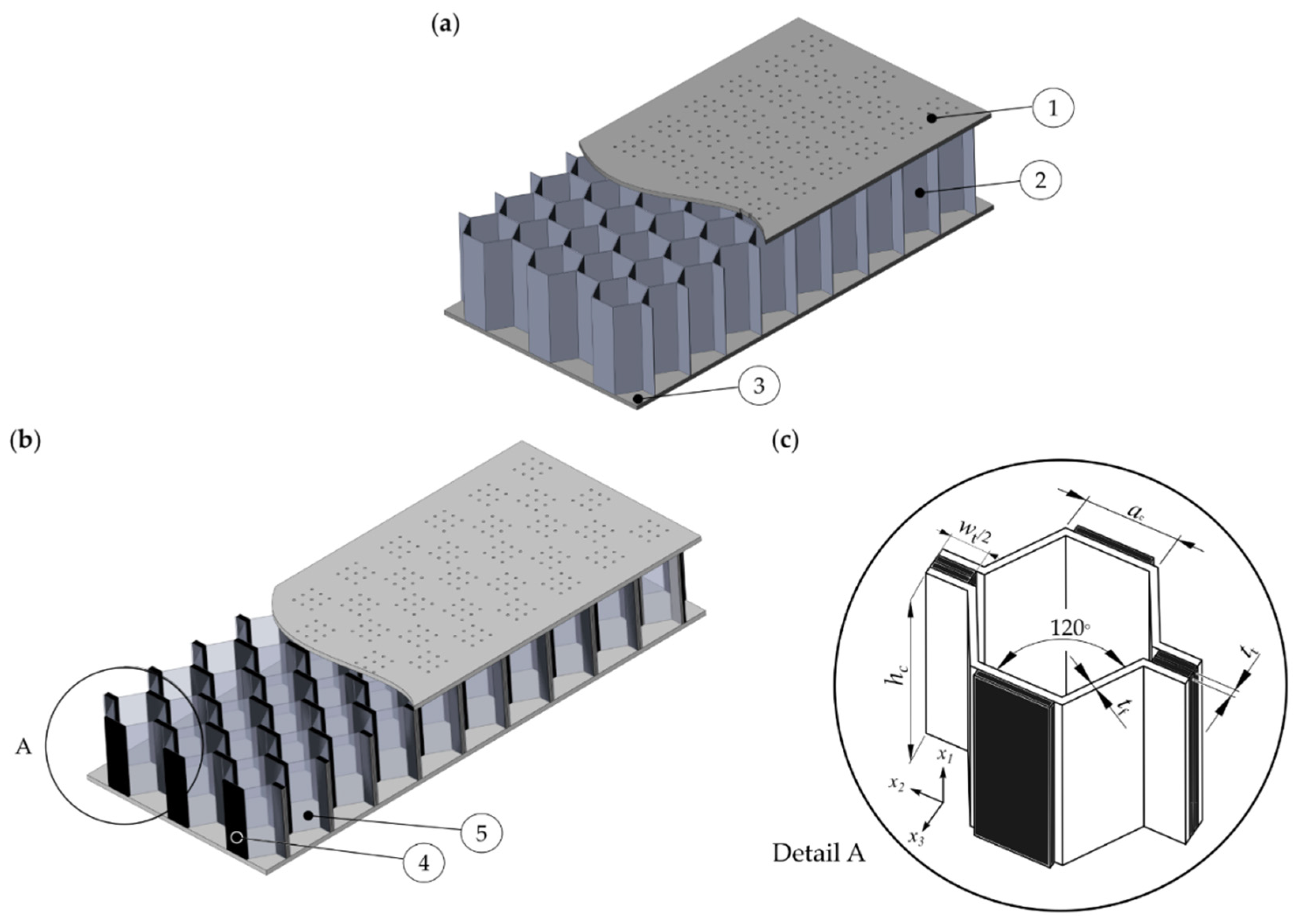
2.1. Structural Design

The basic cell shapes of honeycomb cores are the hexagon, the square, and the flex-core [27]. Thereby, hexagonal cells are by far the most common adhesively bonded honeycomb core structures while most resistance welded and brazed cores have square cells and obtain very narrow cell sizes. With regard to the manufacturing, different designs of square and hexagonal honeycombs made of flexible films and stiff fiber-reinforced materials can be realized (Table 1). For square honeycomb, wall straps with cross-slots could be assembled (Table 1, Config. 1) [9,28]. Changing the design of the connection areas leads to further configurations (Table 1, Config. 2, Config. 3). These square cores require a high manual effort during the assembly process. For the integration of thermoplastic materials, the expansion or corrugation method [27] as well as the manufacturing of folded thermoplastic honeycomb cores [29,30] seem to be more applicable. With regard to advanced acoustic liners, configurations 4 and 5 have the great advantage of enabling a continuous manufacturing process, allowing complex cell shapes and obtaining large flexible wall areas.
In the current study, configuration 4 was chosen because it offers high potential for processing thermoplastic film-based materials, enables a continuous manufacturing process, and achieves the largest flexible wall area (Table 1, Config. 4).
The structural concept of configuration 4 was used to realize advanced hybrid acoustic liner with partially fiber-reinforced support structures (Figure 1b). The flexible wall areas were made of thermoplastic polyurethane (TPU) and the stiff wall areas were made of a carbon fiber-reinforced polyamide 6 tape. For the manufacturing, the concept of folding thermoplastic honeycomb cores structures introduced by Kucher et al. [30] is targeted. In this context, the manufacturing and design concept of a composite lattice truss structure presented by Li et al. [31] indicates an alternative method for realizing the support structure of configuration 4.
In order to investigate the effects of the geometry of the fiber composite structures on the structural mechanical behavior of the core, the width w t , and thickness t t of the tape were varied, while the film thickness t f and the height of the core h c were kept constant. The chosen base material was a unidirectional carbon fiber-reinforced plastic (CFRP) tape with a thickness of 0.13 mm. To create different thicknesses of the reinforcing structure, the tape was stacked on top of each other resulting in total thickness of 0.26 mm, 0.52 mm, and 0.78 mm. The width of the tapes varied up to a proportion of 100%, 75%, or 50% of the side length of a c = 12 mm, respectively. This resulted in nine different geometric configurations, ranging from a thickness of 0.26 mm and a width of 6 mm (T0.26W6) for the thinnest/narrowest configuration to a thickness of 0.78 mm and a width of 12 mm (T0.78W12) for the thickest/widest tape configuration (Table 2).
In order to refer to the stress state of the CFRP tape, the introduced global coordinate system (see Figure 1b) with axes 1, 2, and 3 is aligned according to the orthotropic coordinate system of a representative volume element of a unidirectional laminate, where the 1-direction corresponds to the ‖-direction (fiber direction) and the 2- respectively 3-direction corresponds to the ⊥-direction (transverse to fiber direction) [32].

2.2. Material and Failure Behavior of Polymer and Composite Structures

The core structure consists of two components (TPU film, CFRP tape). The films influenced the acoustic liners damping performance as described in the studies [9,10,33] and were made of TPU. Since the film plays a subordinate role with regard to the stability of the structure due to their significantly lower Young’s modulus (compare Table 3), an isotropic, linear elastic material behavior was assigned to reduce the necessary computational resources for solving the model.
To increase the stability and thus the critical buckling load of the core, CFRP tapes are integrated in each cell as a support structure (see Figure 1). The tapes consist of polyamide 6 reinforced by unidirectional aligned carbon fibers. This material has a transversal isotropic material behavior.
For the estimation of the failure behavior of the composite core structure, the Puck criterion [36] and the Cuntze criterion [37] were applied. For each criterion, the relevant failure mode was determined using the engineering stress and the relevant strengths [32,38].

2.3. Modelling and Numerical Implementation of Honeycomb Core Buckling

A finite element analysis (FEA) of the composite core structure under quasi-static compression was carried out using the simulation environment (Ansys Workbench 2021 R.2., Ansys, Canonsburg, PA, USA). A linear static-structural-mechanical analysis, a linear buckling analysis, and a nonlinear static-structural-mechanical analysis considering large deformations were performed in order to obtain the deformation behavior of the core.
Preliminary investigations regarding the geometry, element selection, and boundary conditions determined the setup of the core modeling. The simulation with solid elements revealed that the normal stresses in the direction of lateral compression ( x 1 -direction) are significantly higher compared to the normal stresses perpendicular to them ( x 2 -, and x 3 -direction). Since the cell walls and tapes are very thin, only very low shear stresses are generated in the tapes and honeycombs. Consequently, the use of shell elements instead of solid elements was advisable, since the stresses in the thickness direction were low. Thus, the simulation was performed using the thin shell element SHELL181 with four nodes (QUAD4) and linear basis functions. The element size of 0.5 mm was determined in a convergence study representing a reasonable compromise between computational effort and numerical accuracy. Depending on the tape width, the model consisted of 6480 to 7200 elements.

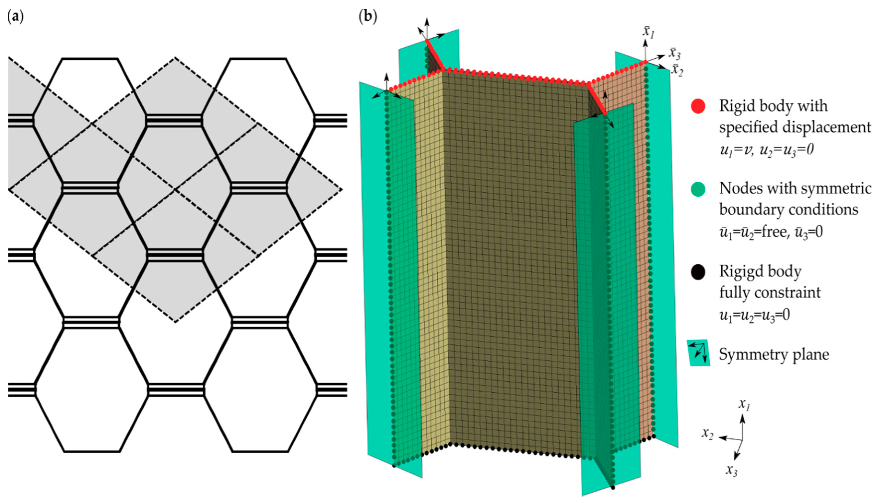
2.3.1. Geometry and Boundary Conditions

A periodic unit cell of the core was defined (Figure 2). The displacements u i were oriented in the direction of the global coordinates x i , and the displacements u ¯ i were oriented in the directions of the local coordinates x ¯ i . The unit cell contains two tapes aligned parallel to the double honeycomb walls and four adjacent bisected single honeycomb walls. The compression of the shell model was modeled in accordance to the ASTM-C365 [39] by applying a constant displacement in the x 1 -direction at the upper edges of the core. A total displacement of 0.02 mm was applied in the linear static analysis and a displacement of 0.5 mm was considered in the nonlinear deformation analysis, which corresponds to approximately 1.67% of the core height.
The displacement in all other directions (global x 2 - and x 3 -directions) was fixed. A fixation in all directions was realized at the lower edges of the core. Depending on the desired manufacturing process, the tapes are either welded or glued to the honeycombs. Therefore, the connection between the adjacent shells of the model was set as a compound. In order to represent the periodicity of the structure, boundary conditions can be introduced at the section planes of the honeycomb edges (in the shell geometry in the form of section edges). For the further numerical analyses, symmetry constraints perpendicular to the section planes of the free-standing cell walls were applied by fixing the displacement in the x 3 ¯ -direction and setting the displacement in each transverse direction as free. This approach has proven to be useful in previous investigations with respect to the realistic representation of the structural failure [17,40,41].

2.3.2. Implementation of Geometrical Imperfection

The structure is predisposed to stability failure in the form of buckling due to the geometry of the walls. In the Ansys FEA software, eigenvalue buckling analysis was used to determine the buckling strength of the core structure. When the critical buckling load was reached, the structure started to deform according to the first buckling mode. This led to a drop in the reaction force and ultimately to a stability failure of the structure. This analysis is also known as linear buckling analysis. However, since imperfections such as nonlinear material behavior, manufacturing tolerances or, in the case of fiber composites, fiber waviness, resin concentration or thickness variations occur in reality, the theoretical buckling strengths are rarely achieved in practice. With the help of a linear buckling analysis, the realistic buckling behavior cannot be described because the force application point shifts during deformation which is not taken into account in the linear analysis. Therefore, for large displacements that occur during buckling of thin structures, it is necessary to perform a geometric nonlinear analysis. A static structural analysis was first performed where the geometry and initial conditions of a unit load case are defined. In the following coupled linear eigenvalue buckling analysis, the deformations related to the first buckling shape are calculated, which occurs at the critical buckling load of the structure for the defined load case. Finally, a nonlinear analysis was carried out to determine the failure of the composite support structure. Therefore, the calculated deformations of the first buckling mode are considered as initial imperfection, a scaling factor f s is applied; a scaling factor of f s = 1 represents the deformation magnitudes at the critical buckling load of the first mode. To show the effect of f s on the stability behavior of the structure, the nonlinear analysis was performed for different scaling factors between 0.05 and 2 for the first buckling mode (Figure 3). Therefore, a tape thickness of t t = 0.26 mm and a width of w t = 12 mm and the option of free boundaries were chosen. Additionally, the stress-strain curve of a geometric linear analysis without imperfection ( f s = 0) was determined.
It can be observed that the stress increase was initially lower with a larger f s , since the buckling and thus the instability of the structure was already further progressed. Thus, less force had to be applied to compress the structure. The two curves correspond to the lowest factor f s = 0.1 and 0.05 ran up to the linear-elastic buckling point close to the geometric-linear solution. An initially analogous behavior also occurs in the study of Jang et al. [40], where the buckling behavior of over expanded metallic honeycomb cores is investigated. Despite the lower degree of geometric imperfection, the two curves with the lowest f s reached comparatively lower stress maxima. For the present study, the scaling factor was set to f s = 0.1 according to the similarity to the force-displacement curve from the study by Jang et al. [40].

2.3.3. Determination of the Fiber Reinforced Plastic Failure Behavior

In order to evaluate and assess the failure behavior of the CFRP tapes, the failure criteria according to Puck and Cuntze were integrated into the Ansys postprocessor in the form of an APDL script as described by Lucas [42] and adapted to the current model. The failure criteria according to Puck and Cuntze allow the differentiation of Fiber failure (FF) and inter-fiber failure (IFF), the characterization of the failure mode and a realistic assessment of the stress state. In order to identify the highest stress state occurring in the structure, both the top and the bottom surface of the shell are considered and the one with the higher stress level was evaluated. In addition, the failure criteria according to Puck allow the predetermination of the fracture angle. The failure criterion according to Cuntze also offers the possibility to calculate a failure of the structure due to inter-fiber shear failure (IFF2).
The APDL script acquires the material properties of the tapes, the occurring global shear and normal stresses, as well as the global strains from the input and output values of the FEA. In case of the Puck failure criteria, the script transforms the global stresses into the stresses in the active plane on an element-by-element basis. The relevant failure criteria for each element are then calculated using the inclination parameters of CFRP [36] and the stresses and failure resistances in the active plane. For the Cuntze criterion, the invariants of the occurring stresses are calculated first. Then, using the curve fitting parameters for CFRP [37], the effective efforts for the relevant failure modes are calculated.

3. Results and Discussion

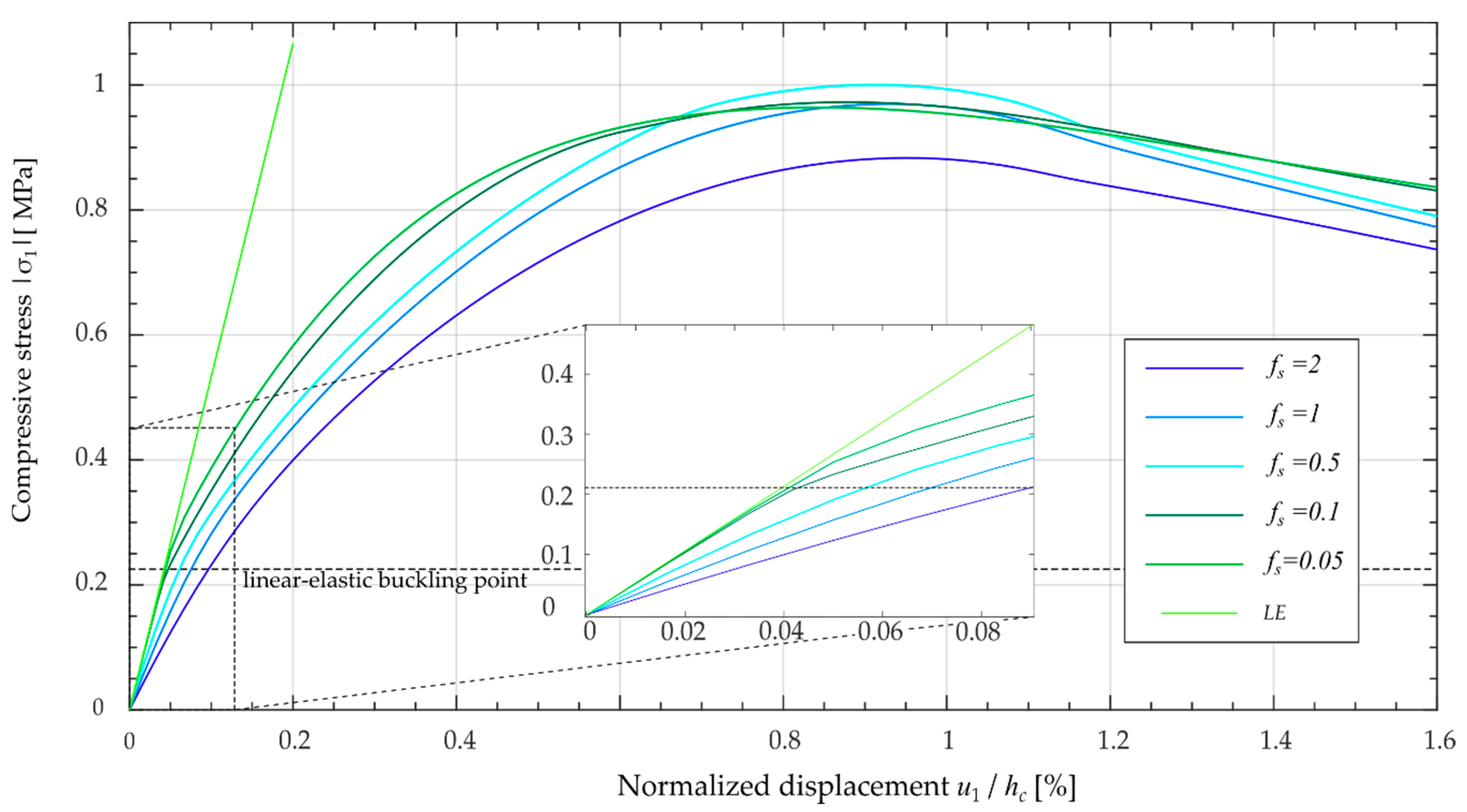
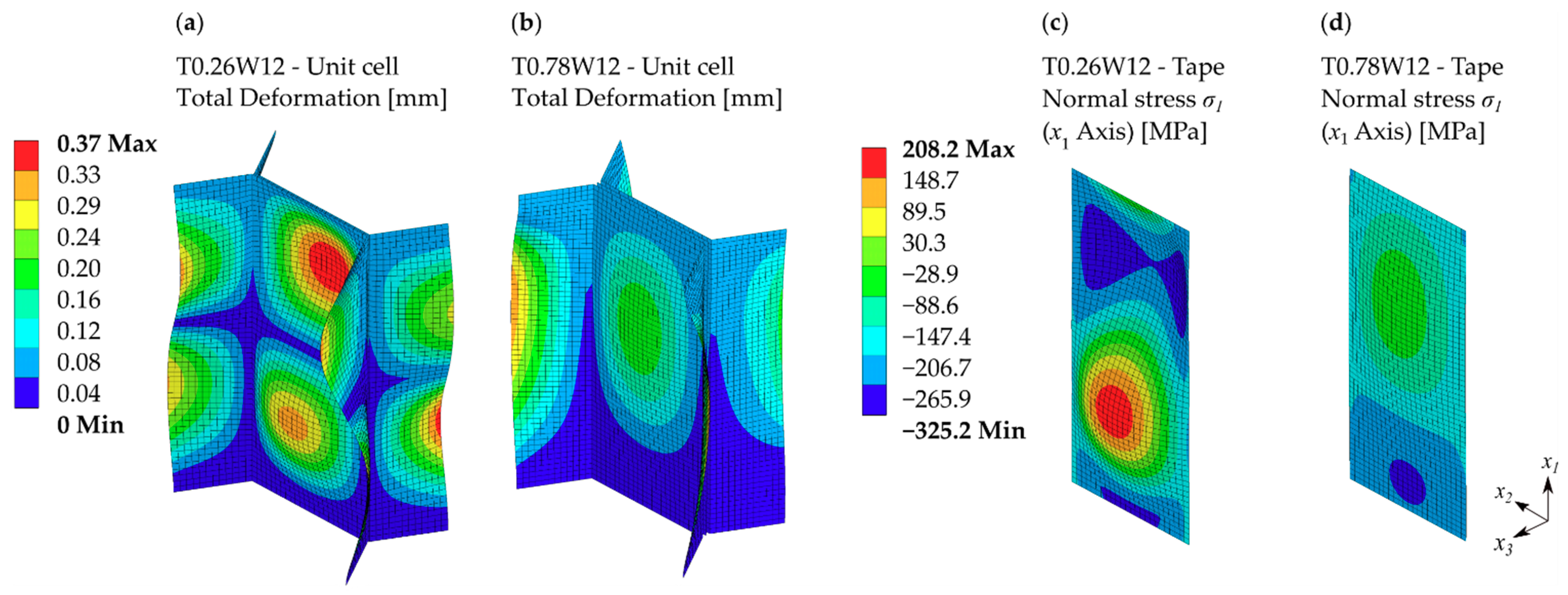
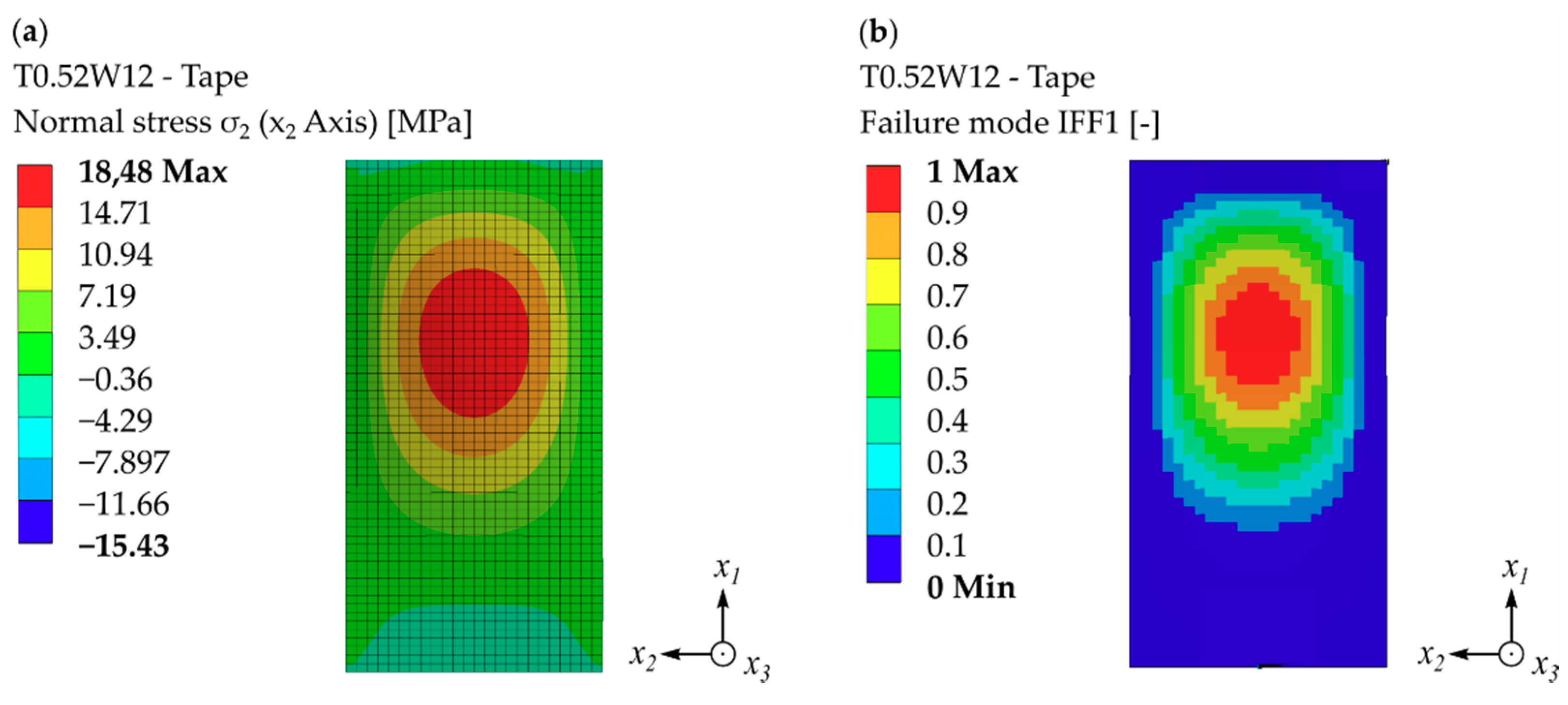
3.1. Resulting Deformation Behavior and Composite Failure

In order to assess the effect of geometrical variations of the tape structure, the nine configurations (see Table 2) were analyzed. The stress-compression responses of the unit cell for the different tape configurations were determined considering large deflections and geometric imperfections (see Figure 4). In the process, the structure is compressed, causing both the rigid CFRP tape and the flexible TPU walls to buckle.
The failure of the structure, represented by black markers, occurs at a displacement range of 0.13% to 0.22% of the core height. This corresponds to a deformation in x 1 -direction of 0.39 mm and 0.66 mm, respectively. Compressive strengths of the core of 0.36 MPa to 4.6 MPa are achieved. The red marks represent the point where the deviation from the initial linear increase of the stress/compression ratio reaches the threshold of 5%. At this point, the limit of linear elastic increase of the deformation is approximately reached.
In contrast to the initial course, where the critical buckling stresses reach much higher values (see Figure 3), the modeled configurations fail at an earlier stage. Consequently, the failure of the structure is a material failure occurring at the micro and meso levels, rather than a stability failure of the entire structure. However, the formation of instabilities in the form of buckling shapes have a significant impact on the failure behavior of the core geometry.
The numerical analysis shows, that for a tape thickness of 0.26 mm, all configurations already exhibit the second buckling shape at the point of failure (Figure 5). In contrast, the thicker configurations exhibit a deformation behavior similar to configuration T0.78W12 (see Figure 5b), corresponding to their first buckling shape.
The differences in the deformation behavior and buckling shapes of the configurations result in an altered stress state. In Figure 5c,d, the fiber-parallel stresses in the x 1 -direction of the tape configurations T0.26W12 and T0.78W12 at the point of failure are displayed. The occurring buckling shapes lead to the induction of tensile and compressive stresses in the x 2 - and x 1 -directions, which reach their maximum in the buckling center. In addition, the buckling induces the shear stresses τ 23 ,   τ 31 , and τ 21 . Since these stresses are very low, they have only a small effect on the failure of the structure.
According to the applied Puck and Cuntze Criteria, the different tape configurations either fail by fiber compression failure or by inter-fiber tension failure (see Table 4).

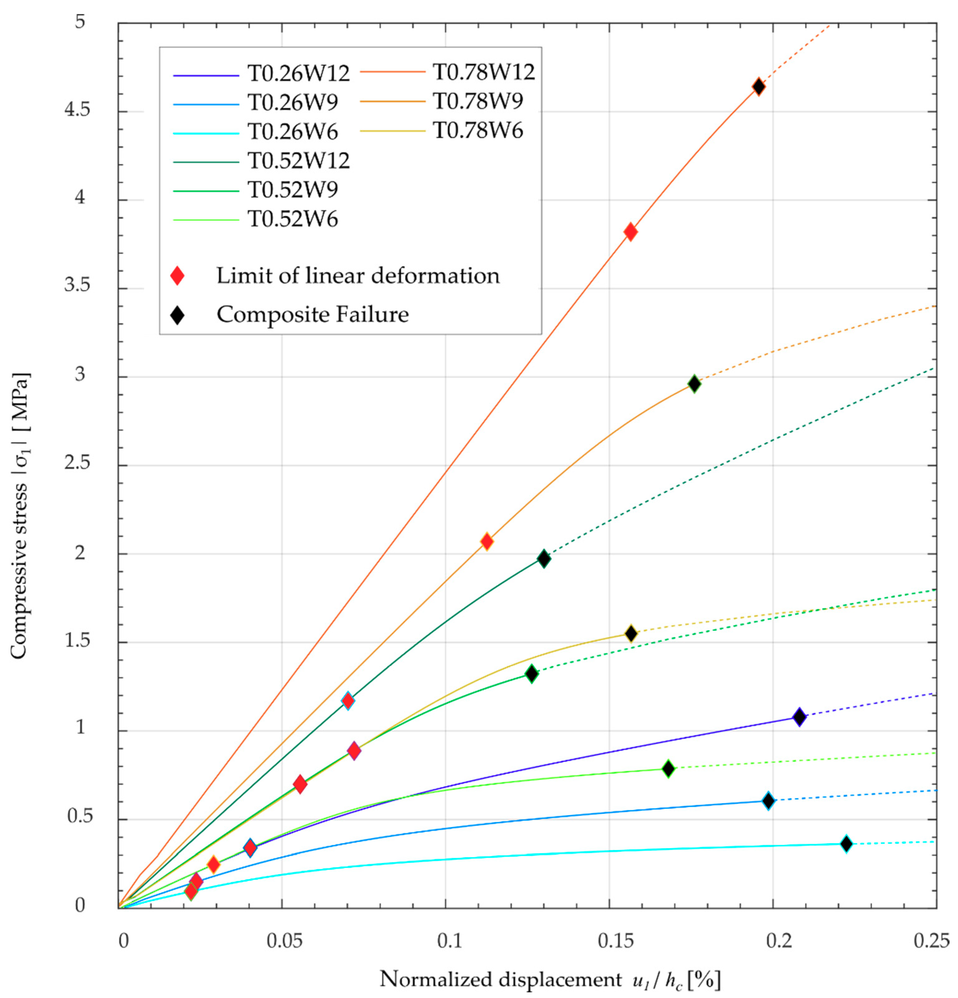
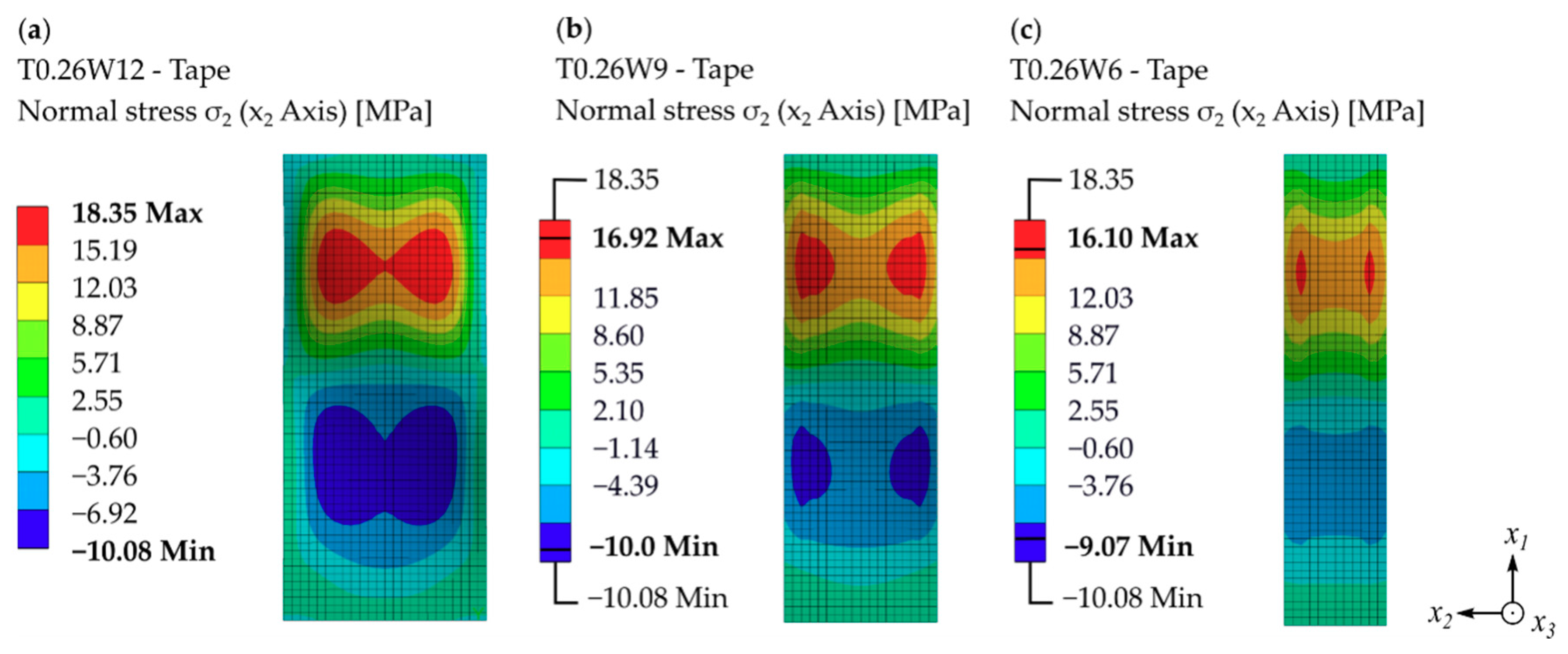
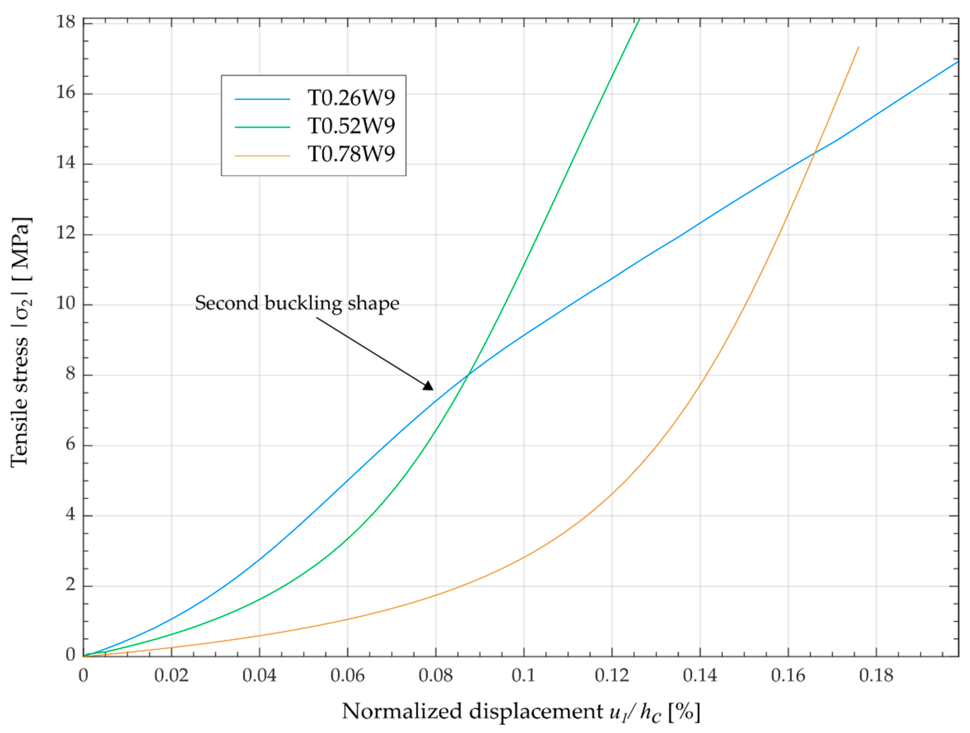
3.2. Influence of Tape Configuration on Failure Behavior

Fiber compressive failure occurs when the compressive stress in the fiber direction exceeds the fiber-parallel compressive strength of R ( ) = 324 MPa. In case of the configurations, the maximum compressive stress is reached without exception on the surfaces of the inner sides of the buckling centers. The reason for the matrix failure is due to the buckle induced tensile stresses at the surfaces of the buckling centers (see Figure 6a). The applied Cuntze criterion for inter-fiber tensile failure indicates the occurrence of failure at the buckling center, which is due to the low tensile strength transverse to the fiber direction R ( + ) = 18.4 MPa of the tapes (Figure 6b).
The tape configurations that have a lower width to height ratio usually fail in the form of fiber compression failure instead of inter-fiber tensile failure due to the generation of lower σ 2 normal stresses across the width. To display this effect, the σ 2 -normal stresses for the three configurations T0.26W12, T0.26W9, and T0.26W6 at the point of failure were compared (Figure 7).
When looking at the failure modes (see Table 4), it is noticeable that the configuration with the thickness of 0.52 mm fails for all three widths due to inter-fiber tensile failure. In contrast, the thicker and thinner configurations fail only in the widest configuration due to inter-fiber tensile failure caused by different buckling shapes. To illustrate the correlation, Figure 8 shows the variation of the stresses σ 2 versus the applied normalized displacement in the x 1 -direction, for three configurations of the same tape width. It is clear that as the tape width decreases, the increase in stress becomes more progressive.
However, in configuration T0.26W9, the formation of the second buckling shape leads to a flattened linear increase in stress. Thus, the T0.52W9 configuration fails at deformation of 0.13% and utilizes only a compression strength of 75% in the fiber direction, while the T0.26W9 configuration does not fail at a lower deformation but achieves a deformation of 0.2% exploiting the full strength in the fiber direction. Therefore, without the occurrence of the second buckling shape, the thin tape configurations would already fail at a lower stress due to inter-fiber tensile failure.

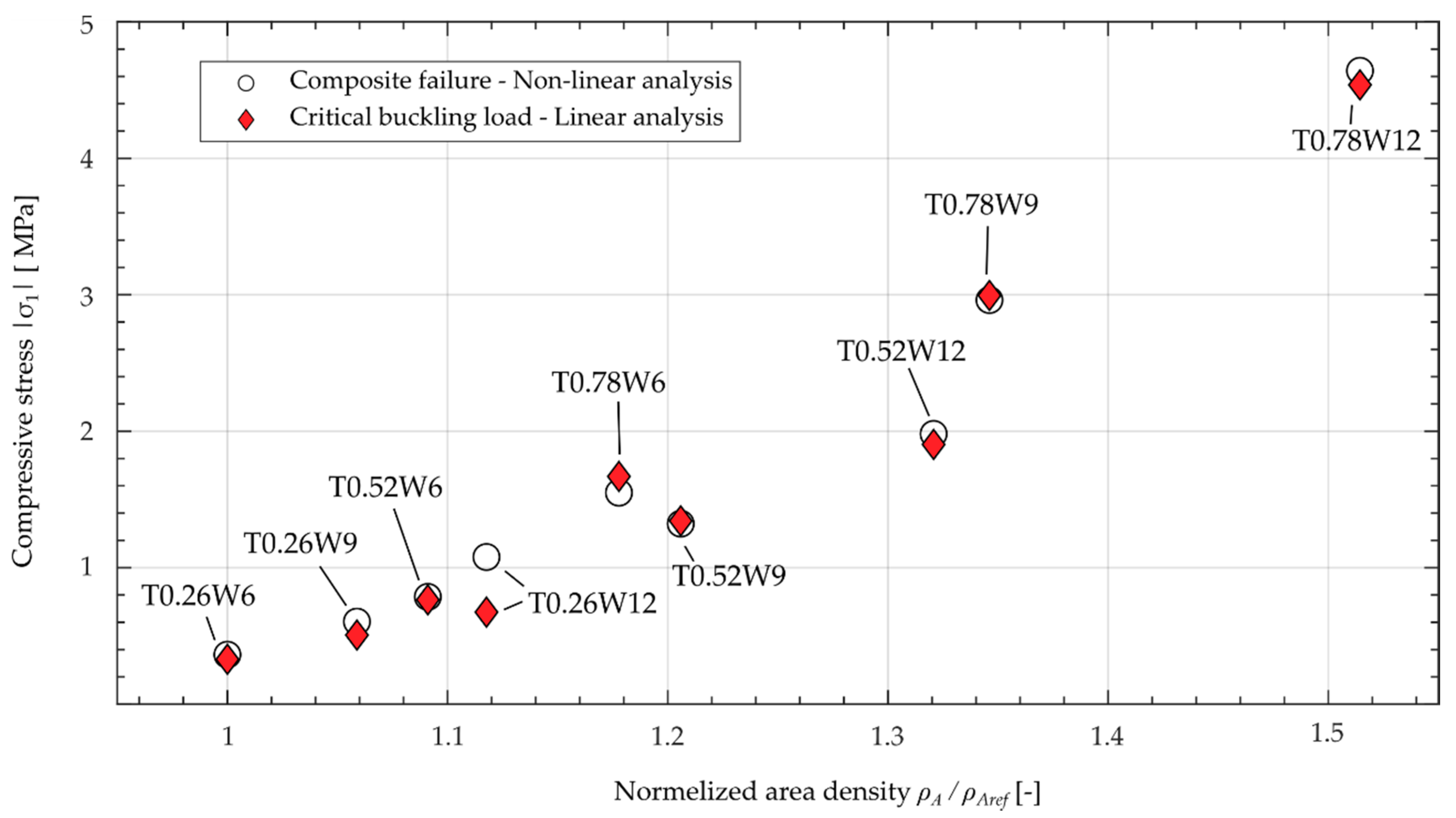
3.3. Resulting Properties of the Composite Core Structure

Depending on the chosen tape thickness and the tape width the maximum compressive strengths and area densities of the composite honeycomb core structure resulted (Figure 9). It can be observed that the thickest and widest configuration shows a 900% increase in the compressive strength of the structure with a 153% increase in weight compared to the thinnest and narrowest configuration. In most cases, the increase in compressive strength relative to the weight increase was nearly linear and two exceptions were the configurations T0.52W9 and T0.52W12. In contrast to the other tape configurations, these two configurations fail comparatively early due to inter-fiber failure. The advantages of the CFRP in the form of high fiber-parallel strengths are consequently not exploited by the configurations.
In general, configurations where the fiber strengths are not utilized to a high degree and premature matrix fracture occurs should not be considered. The development of the buckling shapes is not critical, as long as this does not lead to an excessive increase in stresses transverse to the fiber direction. The buckling shapes (here the second buckling shape) can even have a positive, stiffening effect that prevents inter-fiber fracture.
To prevent an excessive increase in stresses transverse to the fiber, various measures can be taken, including increasing the tape thickness as well as the adjustment of the fiber layout and matrix material. The resulting effects of these structural adjustments on the acoustic performance of the liner must be considered and investigated.

4. Conclusions

A finite element analysis of the deformation behavior of hybrid honeycomb core structure under axial compression in the core thickness direction primarily showed a fiber compression failure according to the Puck and Cuntze criteria. The resulting strengths were similar to the results of the linear buckling analysis of the core and depend on the chosen cross-sectional dimensions of the fiber-reinforced structure. The mechanical response to compression of the core structures showed a failure behavior attributed to material failure at the micro and meso levels rather than stability failure of the entire structure. The variation of the tape width and thickness affected the failure behavior and resulting compression strength of the support structure. In this context, some of these tape configurations lead to the unfavorable occurrence of inter-fiber failure without exploiting the mechanical properties in the fiber direction. An optimized tape configuration offers the potential for the consideration of function integrative acoustic liners in future design processes.

Author Contributions

Conceptualization, N.M., M.D., M.K. and M.N.; investigation, M.N., N.B., M.K. and T.W.; writing—original draft preparation, M.N. and N.B.; writing—review and editing, M.K., M.D., T.W., N.B. and M.N.; visualization, M.N., N.B. and M.K.; supervision, N.M., M.D.; project administration, M.D., M.N.; funding acquisition, N.M. and M.D. All authors have read and agreed to the published version of the manuscript.

Funding

This study was financially supported by the German Research Foundation (DFG) within the framework of Hybsch “Bauweisenentwicklung und Technologiesynthese zur Fertigung zellularer Kunststoffhybridstrukturen für den Einsatz in Schalldämpfern”, project under grant agreement no. MO2231/2-1.

Institutional Review Board Statement

Not applicable.

Informed Consent Statement

Not applicable.

Data Availability Statement

The data presented in the current study are available on request from the corresponding author.

Acknowledgments

We thank our colleagues of the Institute of Fluid Mechanics and Engineering Acoustics of the Technische Universität Berlin, and the German Aerospace Center (DLR), Institute of Propulsion Technology, Department of Turbulence Research in Berlin for the valuable discussions regarding the application and requirements of the honeycomb core structure for the realization of novel acoustic liners.

Conflicts of Interest

The authors declare no conflict of interest.

References

  1. Modler, N.; Winkler, A.; Filippatos, A.; Weck, D.; Dannemann, M. Function-integrative Lightweight Engineering-Design Methods and Applications. Chem. Ing. Tech. 2020, 92, 949–959. [Google Scholar] [CrossRef]
  2. Ruijgrok, G.J.J. Elements of Aviation Acoustics; Delft University Press: Delft, The Netherlands, 1993; ISBN 9062758991. [Google Scholar]
  3. Smith, M.J.T. Aircraft Noise; Cambridge University Press: Cambridge, UK, 1989; ISBN 9780521331869. [Google Scholar]
  4. Azimi, M.; Ommi, F.; Alashti, N.J. Using Acoustic Liner for Fan Noise Reduction in Modern Turbofan Engines. Int. J. Aeronaut. Space Sci. 2014, 15, 97–101. [Google Scholar] [CrossRef]
  5. Zhao, D.; Li, X.Y. A review of acoustic dampers applied to combustion chambers in aerospace industry. Prog. Aerosp. Sci. 2015, 74, 114–130. [Google Scholar] [CrossRef]
  6. Rayleigh, L. The Theory of the Helmholtz Resonator. Proc. R. Soc. Lond. Ser. A Contain. Pap. Math. Phys. Character 1916, 92, 265–275. [Google Scholar]
  7. Barnobi, C.L. Improvement in Acoustic Liner Attenuation in Turbofan Engines by Means of Plasma Synthetic Jet Actuator. Master’s Thesis, Virginia Polytechnic Institute and State University, Blacksburg, VA, USA, 2010. [Google Scholar]
  8. Follet, J.; Betts, J.; Kelly, J. Improvements to Acoustic Liner Broadband Absorption Using Bias Flow. In Proceedings of the 39th Aerospace Sciences Meeting and Exhibit, Reno, NV, USA, 8–11 January 2001. [Google Scholar]
  9. Dannemann, M.; Kucher, M.; Kunze, E.; Modler, N.; Knobloch, K.; Enghardt, L.; Sarradj, E.; Höschler, K. Experimental Study of Advanced Helmholtz Resonator Liners with Increased Acoustic Performance by Utilising Material Damping Effects. Appl. Sci. 2018, 8, 1923. [Google Scholar] [CrossRef] [Green Version]
  10. Knobloch, K.; Enghardt, L.; Bake, F. (Eds.) Investigation of Flexible Walls for Acoustic Liners. In Proceedings of the 25th AIAA/CEAS Aeroacoustics Conference, Delft, The Netherlands, 20–23 May 2019. [Google Scholar]
  11. Fan, H.K.; Lam, G.C.; Leung, R.C.K. Spatio-temporal aeroacoustic-structural responses of cavity-backed elastic panel liner exposed to grazing duct flow. J. Fluids Struct. 2021, 102, 103228. [Google Scholar] [CrossRef]
  12. Różyło, P.; Wysmulski, P.; Falkowicz, K. Fem and Experimental Analysis of Thin-Walled Composite Elements under Compression. Int. J. Appl. Mech. Eng. 2017, 22, 393–402. [Google Scholar] [CrossRef] [Green Version]
  13. Falkowicz, K.; Mazurek, P.; Różyło, P.; Wysmulski, P.; Smagowski, W. Experimental and Numerical Analysis of the Compression of a Thin-Walled Composite Plate. Adv. Sci. Technol. Res. J. 2016, 10, 177–184. [Google Scholar] [CrossRef] [Green Version]
  14. McFarland, R.K., Jr. Hexagonal Cell Structures under Post-Buckling Axial Load. AIAA J. 1963, 1, 1380–1385. [Google Scholar] [CrossRef]
  15. Wierzbicki, T. Crushing analysis of metal honeycombs. Int. J. Impact Eng. 1983, 1, 157–174. [Google Scholar] [CrossRef]
  16. Sun, Z.; Shi, S.; Guo, X.; Hu, X.; Chen, H. On compressive properties of composite sandwich structures with grid reinforced honeycomb core. Compos. Part B Eng. 2016, 94, 245–252. [Google Scholar] [CrossRef]
  17. Aktay, L.; Johnson, A.F.; Kröplin, B.-H. Numerical modelling of honeycomb core crush behaviour. Eng. Fract. Mech. 2008, 75, 2616–2630. [Google Scholar] [CrossRef]
  18. Vondřejc, J.; de Geus, T.W.J. Energy-based comparison between the Fourier-Galerkin method and the finite element method. J. Comput. Appl. Math. 2020, 374, 112585. [Google Scholar] [CrossRef] [Green Version]
  19. Liu, N.; Jeffers, A.E. Isogeometric analysis of laminated composite and functionally graded sandwich plates based on a layerwise displacement theory. Compos. Struct. 2017, 176, 143–153. [Google Scholar] [CrossRef]
  20. Wu, E.; Jiang, W.-S. Axial crush of metallic honeycombs. Int. J. Impact Eng. 1997, 19, 439–456. [Google Scholar] [CrossRef]
  21. Seemann, R.; Krause, D. Numerical modelling of Nomex honeycomb sandwich cores at meso-scale level. Compos. Struct. 2017, 159, 702–718. [Google Scholar] [CrossRef]
  22. Hähnel, F.; Wolf, K.; Hauffe, A.; Alekseev, K.A.; Il’dus, M.Z. Wedge-shaped folded sandwich cores for aircraft applications: From design and manufacturing process to experimental structure validation. CEAS Aeronaut. J. 2011, 2, 203–212. [Google Scholar] [CrossRef]
  23. Asprone, D.; Auricchio, F.; Menna, C.; Morganti, S.; Prota, A.; Reali, A. Statistical finite element analysis of the buckling behavior of honeycomb structures. Compos. Struct. 2013, 105, 240–255. [Google Scholar] [CrossRef]
  24. Yuan, W.; Song, H.; Lu, L.; Huang, C. Effect of local damages on the buckling behaviour of pyramidal truss core sandwich panels. Compos. Struct. 2016, 149, 271–278. [Google Scholar] [CrossRef]
  25. Wang, B.; Hu, J.; Li, Y.; Yao, Y.; Wang, S.; Ma, L. Mechanical properties and failure behavior of the sandwich structures with carbon fiber-reinforced X-type lattice truss core. Compos. Struct. 2018, 185, 619–633. [Google Scholar] [CrossRef]
  26. Djama, K.; Michel, L.; Ferrier, E.; Gabor, A. Numerical modelling of a truss core sandwich panel: Influence of the connectors’ geometry and mechanical parameters on the mechanical response. Compos. Struct. 2020, 245, 112335. [Google Scholar] [CrossRef]
  27. Bitzer, T. Honeycomb Technology: Materials, Design, Manufacturing, Applications and Testing; Springer: Dordrecht, The Netherlands, 1997; ISBN 978-94-010-6474-3. [Google Scholar]
  28. Yu, G.-C.; Feng, L.-J.; Wu, L.-Z. Thermal and mechanical properties of a multifunctional composite square honeycomb sandwich structure. Mater. Des. 2016, 102, 238–246. [Google Scholar] [CrossRef]
  29. John, M.; Petersilge, M.; Geyer, A.; Schlimper, R.; Pflug, J. (Eds.) Modeling and Assessment of Folded Thermoplastic Honeycomb Core Sandwich Structures Using a Representative Volume Element. In Proceedings of the 12th International Conference on Sandwich Structures ICSS-12, Lausanne, Switzerland, 19–22 August 2018; EPFL-CCLab Composite Construction Laboratory: Lausanne, Switzerland, 2018. [Google Scholar]
  30. Kucher, M.; Dannemann, M.; Adam, F.; Modler, N.; Zichner, M. Verfahren und Vorrichtung zur Kontinuierlichen Herstellung Gefalteter Zellstrukturen, Sowie Gefaltete Zellstruktur; Technische Universitaet Dresden: Dresden, Germany, 2019. [Google Scholar]
  31. Li, W.; Sun, F.; Wang, P.; Fan, H.; Fang, D. A novel carbon fiber reinforced lattice truss sandwich cylinder: Fabrication and experiments. Compos. Part A Appl. Sci. Manuf. 2016, 81, 313–322. [Google Scholar] [CrossRef]
  32. Puck, A. Festigkeitsanalyse von Faser-Matrix-Laminaten: Modelle für die Praxis; Hanser: München, Germany, 1996; ISBN 3446181946. [Google Scholar]
  33. Bake, F.; Knobloch, K. Novel liner concepts. CEAS Aeronaut. J. 2019, 10, 123–136. [Google Scholar] [CrossRef] [Green Version]
  34. Schürmann, H. Konstruieren Mit Faser-Kunststoff-Verbunden, 2nd ed.; Springer: Berlin/Heidelberg, Germany, 2007; ISBN 9783540721901. [Google Scholar]
  35. Huschle, T. DFG SPP 1712. Available online: http://www.wbk.kit.edu/wbkintern/Forschung/Projekte/SPP-1712/index.php (accessed on 28 January 2021).
  36. Puck, A.; Kopp, J.; Knops, M. Guidelines for the determination of the parameters in Puck’s action plane strength criterion. Compos. Sci. Technol. 2002, 62, 371–378. [Google Scholar] [CrossRef]
  37. Cuntze, R.G.; Freund, A. The predictive capability of failure mode concept-based strength criteria for multidirectional laminates. Compos. Sci. Technol. 2004, 64, 343–377. [Google Scholar] [CrossRef]
  38. Hinton, M.J.; Kaddour, A.S.; Soden, P.D. (Eds.) Failure Criteria in Fibre Reinforced Polymer Composites: The World-Wide Failure Exercise; Elsevier: Amersterdam, The Netherlands; London, UK, 2004; ISBN 008044475X. [Google Scholar]
  39. D30 Committee. Standard Test Method for Flatwise Compressive Properties of Sandwich Cores; ASTM International: West Conshohocken, PA, USA, 2016. [Google Scholar]
  40. Jang, W.Y.; Kyriakides, S. On the buckling and crushing of expanded honeycomb. Int. J. Mech. Sci. 2015, 91, 81–90. [Google Scholar] [CrossRef]
  41. Liu, L.; Meng, P.; Wang, H.; Guan, Z. The flatwise compressive properties of Nomex honeycomb core with debonding imperfections in the double cell wall. Compos. Part B Eng. 2015, 76, 122–132. [Google Scholar] [CrossRef]
  42. Lucas, P. Zur Auslegung von Faserverbund-Bandagen für Elektromotoren, 1st ed.; Technische Universität Dresden, Institut für Leichtbau und Kunststofftechnik: Dresden, Germany, 2020; ISBN 9783867806299. [Google Scholar]
Figure 1. (a) Conventional Helmholtz resonator liner with perforated upper layer (1), cell core (2), and bottom layer (3), (b) new concept of a hybrid acoustic liner with fiber-reinforced tape (4) and flexible cell wall (5) and (c) detail of the hybrid cell core structure.
Jcs 05 00116 g001
Figure 2. (a) Selection of unit cell for buckling analysis, (b) unit cell with applied loads and boundary conditions.
Jcs 05 00116 g002
Figure 3. Effect of geometric imperfection on stress/strain behavior of the structure using different scaling factors f s for the first buckling mode.
Jcs 05 00116 g003
Figure 4. Stress-strain curves of the tape configurations with theoretical structural response.
Jcs 05 00116 g004
Figure 5. Total deformation of the unit cell of the configurations (a) T0.26W12 and (b) T0.78W12 and the stress state ( x 1 -direction) of the tape at the point of failure of the configurations (c) T0.26W12 and (d) T0.78W12 at a deformation-scaling factor of 6.0.
Jcs 05 00116 g005
Figure 6. (a) Plot of the distribution of σ 2 stresses of the tape configuration T0.56W12 and (b) the inter-fiber tensile failure mode (IFF1) for all elements of the tape at the point of failure.
Jcs 05 00116 g006
Figure 7. Comparison of the normal stress σ 2 distribution of the three tape widths (a) 12 mm, (b) 9 mm and (c) 6 mm with a tape thickness of 0.26 mm at the point of failure.
Jcs 05 00116 g007
Figure 8. Stresses transverse to fiber direction vs. normalized displacement in x 1 -direction of the unit cell.
Jcs 05 00116 g008
Figure 9. Comparison of calculated composite failure of the nonlinear analysis and the critical buckling load of the linear analysis over the normalized area density.
Jcs 05 00116 g009
Table 1. Design variants of new acoustic liners.
SquareSquareSquareHexagonalHexagonal
Cell structure Jcs 05 00116 i001 Jcs 05 00116 i001 Jcs 05 00116 i001 Jcs 05 00116 i002 Jcs 05 00116 i002
Sketch of core Jcs 05 00116 i003 Jcs 05 00116 i004 Jcs 05 00116 i005 Jcs 05 00116 i006 Jcs 05 00116 i007
Table 2. Analyzed tape configurations and the corresponding geometric dimensions.
Tape   Width   w t   [ mm ]
1296
Tape   thickness   t t [mm]0.78 Jcs 05 00116 i008 Jcs 05 00116 i009 Jcs 05 00116 i010
0.52 Jcs 05 00116 i011 Jcs 05 00116 i012 Jcs 05 00116 i013
0.26 Jcs 05 00116 i014 Jcs 05 00116 i015 Jcs 05 00116 i016
Table 3. Material properties of investigated components [34] (p. 202), [35].
Property 1SymbolUnitQuantity
Thermoplastic Polyurethane
Young’s modulus E MPa1647
Poisson ratio υ -0.4078
Density ρ g/cm³1.178
Tensile Strength R MPa48.84
Carbon fiber reinforced polyamide 6
Youngs modulus in E MPa103,400
Youngs modulus E MPa3600
Poisson ratio / υ -0.29
Poisson ratio / υ -0.37
Shear modulus / G MPa1810
Shear modulus matrix G MPa1193
Tensile strength R ( + ) MPa1637
Tensile strength ⊥ R ( + ) MPa18.4
Compression strength R ( ) MPa324
Compression strength R ( ) MPa91
Shear strength / R MPa36.6
Shear strength ⊥/⊥ R / MPa19.5
Density ρ g/cm³1.450
1 In fiber direction (‖) and perpendicular to the fiber direction (⊥).
Table 4. Mode effort of the relevant failure criteria according to Puck and Cuntze as well as the corresponding structural stress and structural strain in the x 1 -direction for the different tape configurations at the point of failure.
Tape thickness [mm]0.780.520.26
Tape width [mm]129612961296
Puck
Fiber compression failure [-]0.991.001.000.730.750.980.951.001.00
Inter-fiber tensile failure [-]1.000.940.501.001.001.001.000.960.95
Inter-fiber compression failure [-]0.260.220.140.250.210.190.380.300.24
Cuntze
Inter-fiber tensile failure- IFF1 [-]1.000.940.501.001.001.001.000.960.95
Inter-fiber shear failure- IFF2 [-]0.020.010.020.020.010.040.070.080.18
Inter-fiber compression failure- IFF3 [-]0.190.170.090.170.160.070.110.110.11
σ 1 [N/mm2]4.642.961.551.981.320.791.070.60.36
ϵ 1 [%]0.190.180.160.130.130.170.210.200.22
Publisher’s Note: MDPI stays neutral with regard to jurisdictional claims in published maps and institutional affiliations.

