Article

The Effect of Pre-Bond Contamination by Thermal Degradation and De-Icing Fluid on the Tensile Strength of Scarf Composite Bonded Joints

by
Konstantinos Tserpes
* and
Elli Moutsompegka
Laboratory of Technology & Strength of Materials, Department of Mechanical Engineering & Aeronautics, University of Patras, 26500 Patras, Greece
*
Author to whom correspondence should be addressed.
J. Compos. Sci. 2021, 5(7), 168; https://0-doi-org.brum.beds.ac.uk/10.3390/jcs5070168
Submission received: 27 May 2021 / Revised: 22 June 2021 / Accepted: 24 June 2021 / Published: 28 June 2021
(This article belongs to the Special Issue Feature Papers in Journal of Composites Science in 2021)

Abstract

:
The synergistic effect of pre-bond contamination by thermal degradation and de-icing fluid on the tensile behavior of scarf composite bonded joints has been investigated experimentally. The contamination types considered are related to the repair process of composite aircraft structures. Three contamination scenarios have been considered: namely, thermal degradation (TD) and a combination of thermal degradation with two different levels of de-icing fluid (TD+DI1 and TD+DI2). DI2 is more severe than DI1. Contamination has been applied to one of the adherents while the other one has been intentionally left intact. Tension tests have been conducted on single-lap shear specimens. The experimental results were compared with the reference samples (REF) showing an increase in tensile strength for the TD specimens and a decrease in tensile strength for the TD+DI1 and TD+DI2 specimens. After the tension tests, the failure surfaces were evaluated to get a better insight of the failure mechanisms of the bondline and to assess the effect of contamination. The TD specimens presented an increased cohesive failure which is consistent with the increase of the failure load, while the combined contamination caused the failure of the composite adherents which again is consistent with the decrease of tensile strength of the scarf specimens.

1. Introduction

With the increasing use of composite materials in the aeronautics industry [1], the need for the repair of damaged structural parts using composite adhesive joints has innately emerged, as it excels in not requiring a complete replacement of the damaged part with a new one or even any change of the initial shape of the component.
Regarding the existing certification requirements for civil aircrafts, the EASA’s document AMC20-29 skins [2], which sets forth requirements for damage tolerance and fatigue evaluation or primary composite airframe structure, states that safety-critical structures must be demonstrated, by experiments and analysis, to exceed the design ultimate load. Additionally, it states that “repeatable and reliable non-destructive inspection techniques must be established that ensure the strength of each joint”.
However, despite the numerous advantages of the adhesive joining method over the conventional joining techniques, such as more uniform stress distribution and better fatigue behavior [3,4], the main factors that hinder the regulatory compliance of bonded joints, and thus the wider application of adhesive joints, is the sensitivity of the bondline integrity to the environmental factors and the lack of existing NDT techniques that can detect kissing bonds [5,6].
The environmental conditions—which may affect not only the mechanical properties of the structural part itself but also the bonding in a repair situation—are numerous. The effect of the operating environments in terms of temperature has been thoroughly investigated as carbon fiber reinforced (CFRP) aircraft parts may be exposed to high temperatures during service [6,7]. For example, fuselage parts struck by lightning or external source of heat placed near the aircraft part, e.g., wing parts that are close to the engine. The exposure to high temperatures has been reported to cause local overheating and damage to the matrix as well as to undermine the bond performance of repair joints [6,7,8,9].
Additionally, runway de-icing fluid is one of the most commonly encountered substances that composite structures may be exposed to, as it can be swirled up from the runway and onto the outer parts of the aircraft. During the patch repair of composite components, residues or transfer of de-icing fluid onto adherent surfaces may occur as a result of inadequate cleaning. After drying, the potassium formate (KF), which is present in the de-icing fluid, forms a thin layer onto the CFRP component, thus affecting the bonding quality [10,11]. In contrast with other environmental factors, limited research has been published on the effect of runway de-icing fluid, while a growing body of field reports from airline operators indicate that KF may cause accelerated structural degradation on composite aircraft brakes, reducing brake life and introducing the possibility of brake failure [9]. Moutsompegka et al. [10] reported a detrimental effect of the de-icing fluid on both the mode I and mode II fracture toughness of adhesive composite bonded joints.
The objective of the present work it to determine the effect of following a combined contamination scenario with thermal degradation and subsequent runway de-icing fluid on the tensile strength of scarfed composite joints.

2. Fabrication and Pre-Bond Contamination
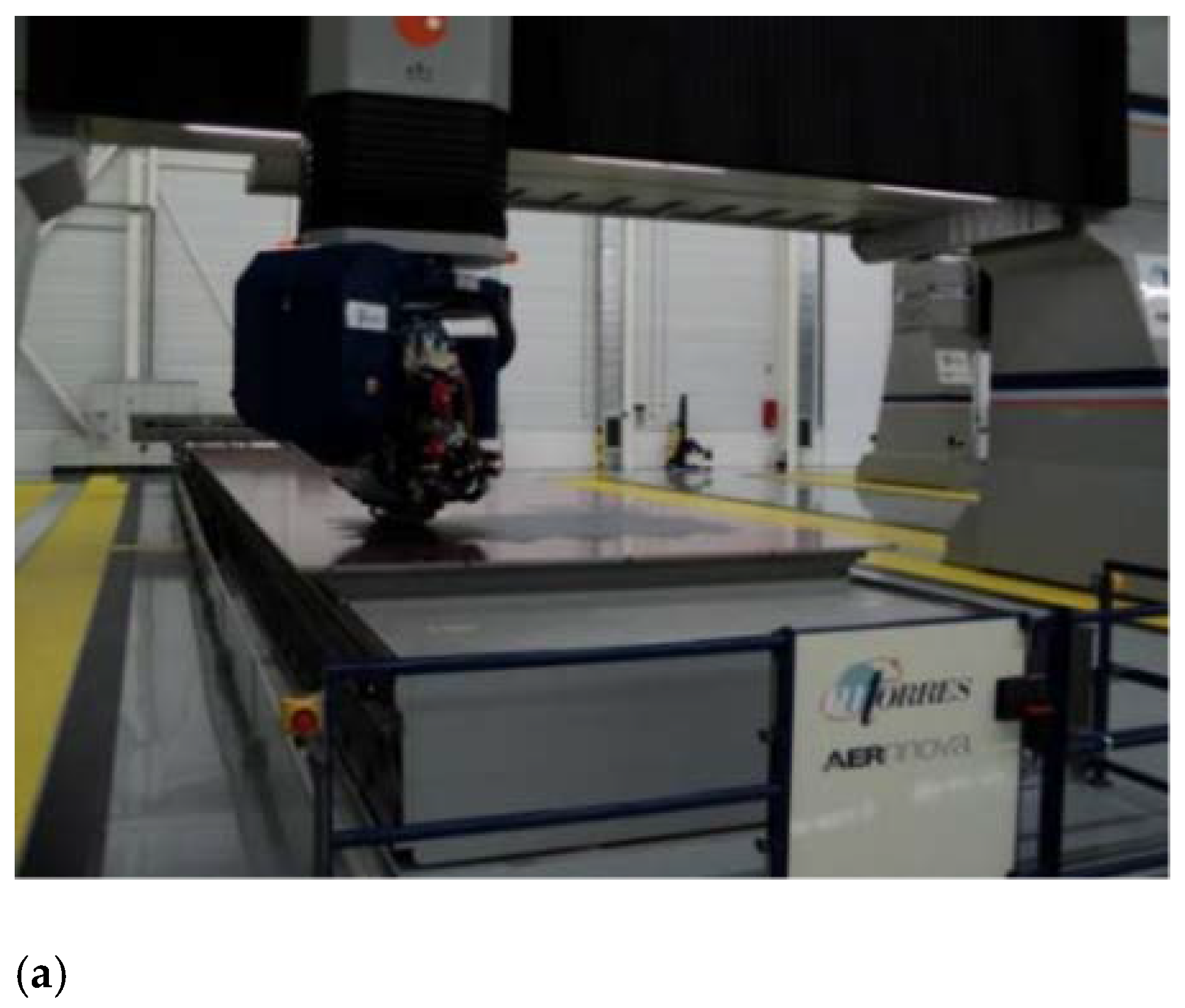
2.1. Materials

The experimental investigation used HexPly M21E/IMA unidirectional epoxy/carbon prepreg for composite scarf joint adherents, which was developed for Airbus aircraft applications. The sample plates were produced by Aernnova Composites using the liquid water-based silicone-containing release agent Frekote®® C-600 in order to obtain smooth surfaces. Regarding the structural layout, CFRP monolithic structures with a layout sequence of [02, ±45]s were manufactured according to the Airbus AIPS 03-02-019 standard for CFRP (“Manufacture of monolithic parts with thermoset prepreg materials”). The CFRP laminates for the coupons were manufactured using the automated tape laying (ATL) technique (Figure 1a). The diagram showing the applied vacuum bag is given in Figure 1b.

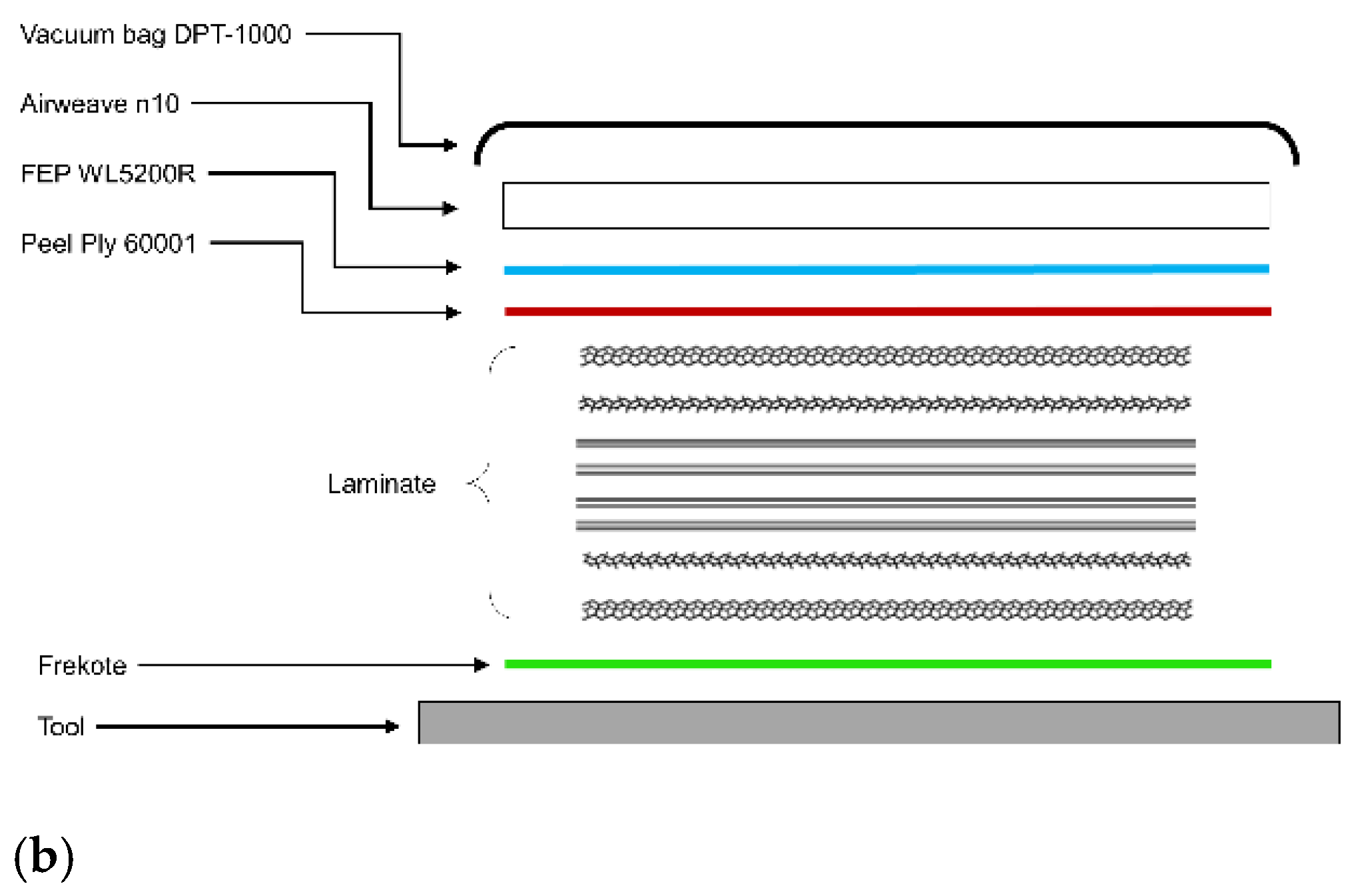
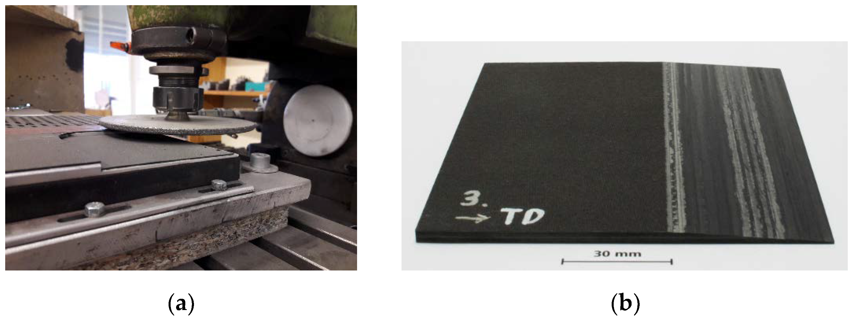
2.2. Adherents’ Preparation

A thorough cleaning process was followed to remove any manufacturing induced contaminations before the bonding procedure. The CFRP plates were cleaned with isopropanol-soaked tissues, grinding and cleaning with MEK until a clean surface was achieved. To ensure that, after each cleaning step the adherents were examined by performing spectroscopic surface characterization (XPS) measurements. This process is described in detail in [12].
When damage is detected, the aircraft part is locally scarfed to remove the damaged outer layers, which are then substituted with a patch that is bonded over the scarfed area in order to restore the load-carrying capacity. The scarfed samples used in this work were rectangular and consisted of two CFRP plates scarfed by milling with a ratio of 1:17 (Figure 2a) and were then manually grinded and cleaned with methyl ethyl ketone (MEK) to remove any handling contamination from thermoplastic residues resulting from the milling process. Lastly, the samples were cut to the final size using dry diamond cutting (Figure 2b).

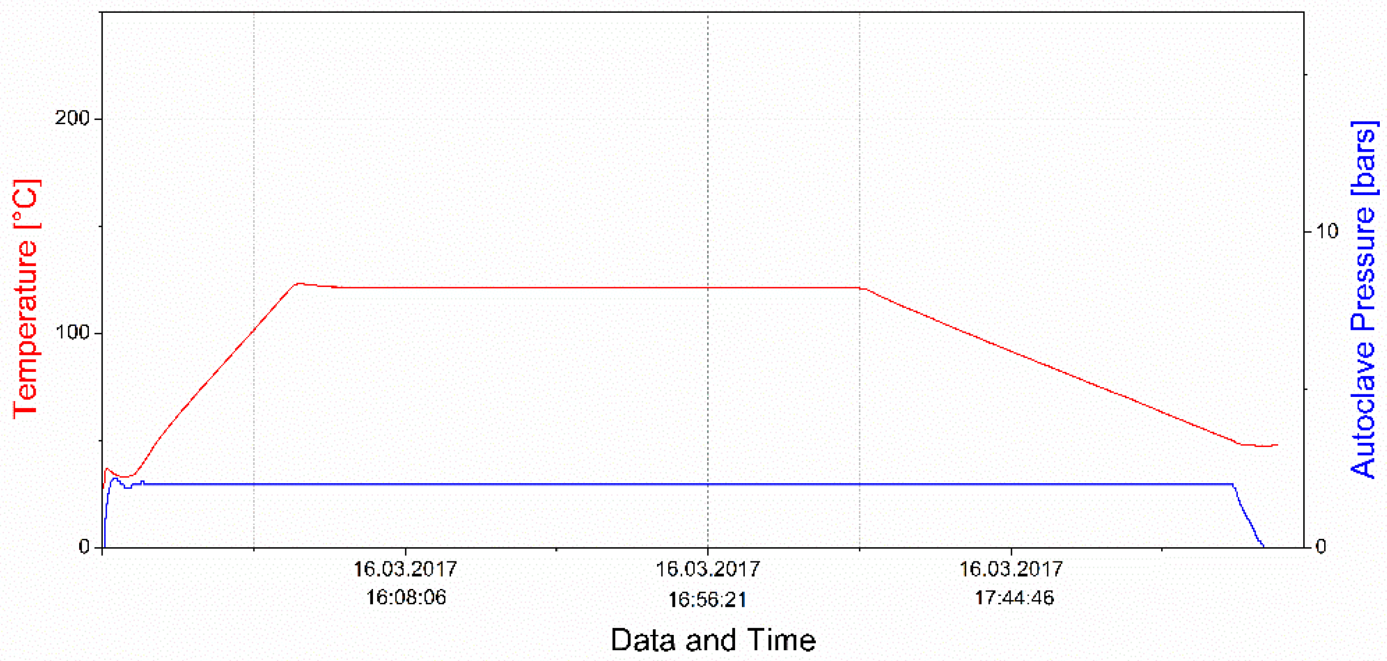
2.3. Pre-Bond Contamination and Bonding

In all the contamination cases, one of the adherends was contaminated while the other was intentionally left in the respective reference state, a setup intended to replicate the real-life application of repair patches. The de-icer (DI) used was SAFEWAY®® KF from CLARIANT, which contains potassium formate (KF) as the freezing point depressant. It was diluted with demineralized water to obtain solutions with the following concentrations in 2 vol% (DI1) and 7 vol% (DI2) and it was applied to the surfaces by dip-coating in the respective aqueous solution. Finally, drying was performed in an oven for 2 h at 40 °C in air. Subsequently, acclimatization at room temperature was allowed for at least 24 h.
All thermal impact (TD) treatments were carried out in an oven with air circulation. The samples were placed inside the oven and then underwent the heating phase at different temperatures. The following two different temperatures were used to realize two different levels of thermal impact: 220 °C for TD1 and 260 °C for TD2. Once the indicated temperature was reached, the samples remained inside the oven for 2 h. Prior to both the surface inspection and the subsequent steps of the bonding process, all samples were grinded down to the fibers (using Si-free sandpaper, grit size 120).
All the samples were bonded in the autoclave using the adhesive FM®® 300-2 (0.25 mm), which is specially designed for bonded repair. The respective curing cycle is shown in Figure 3.

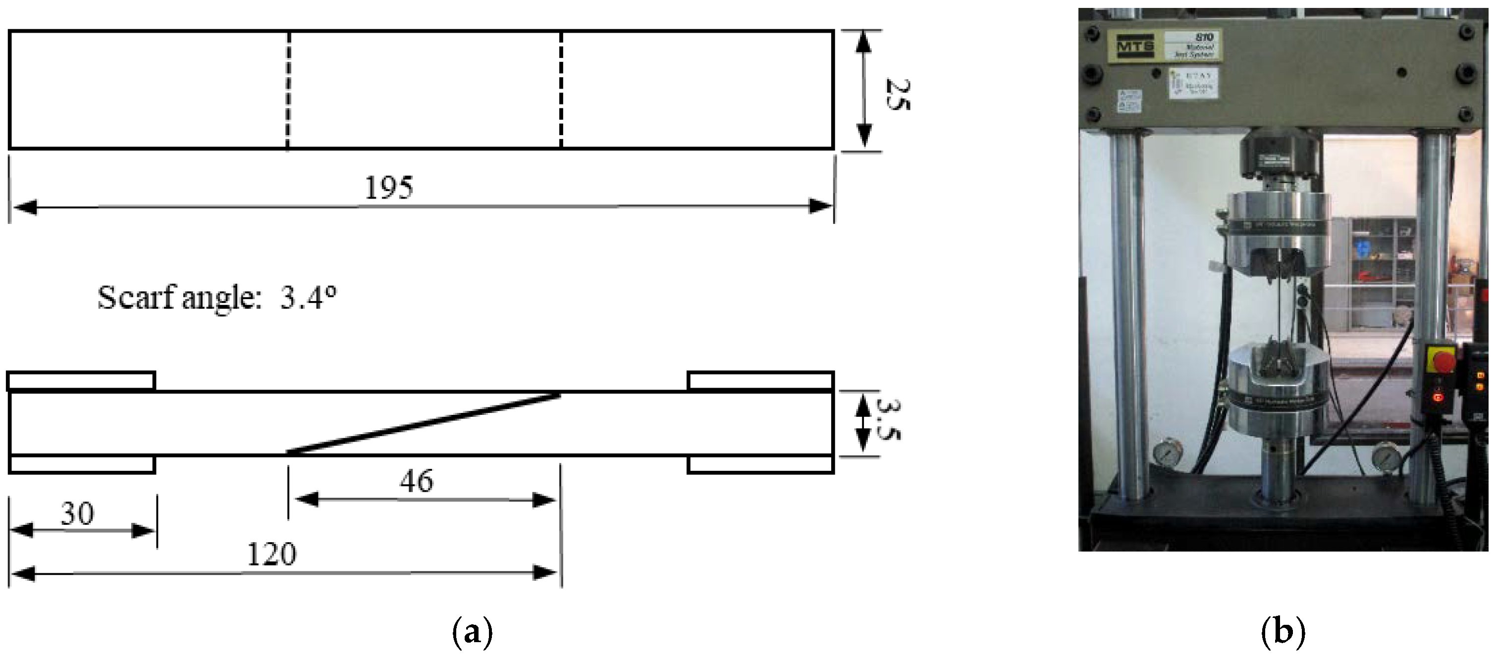
3. Experimental Procedure
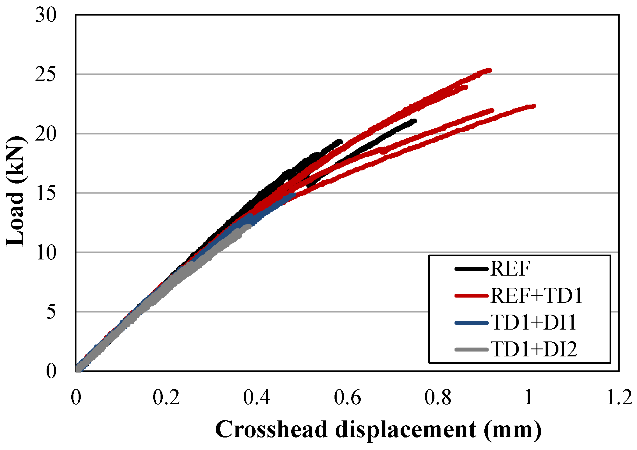
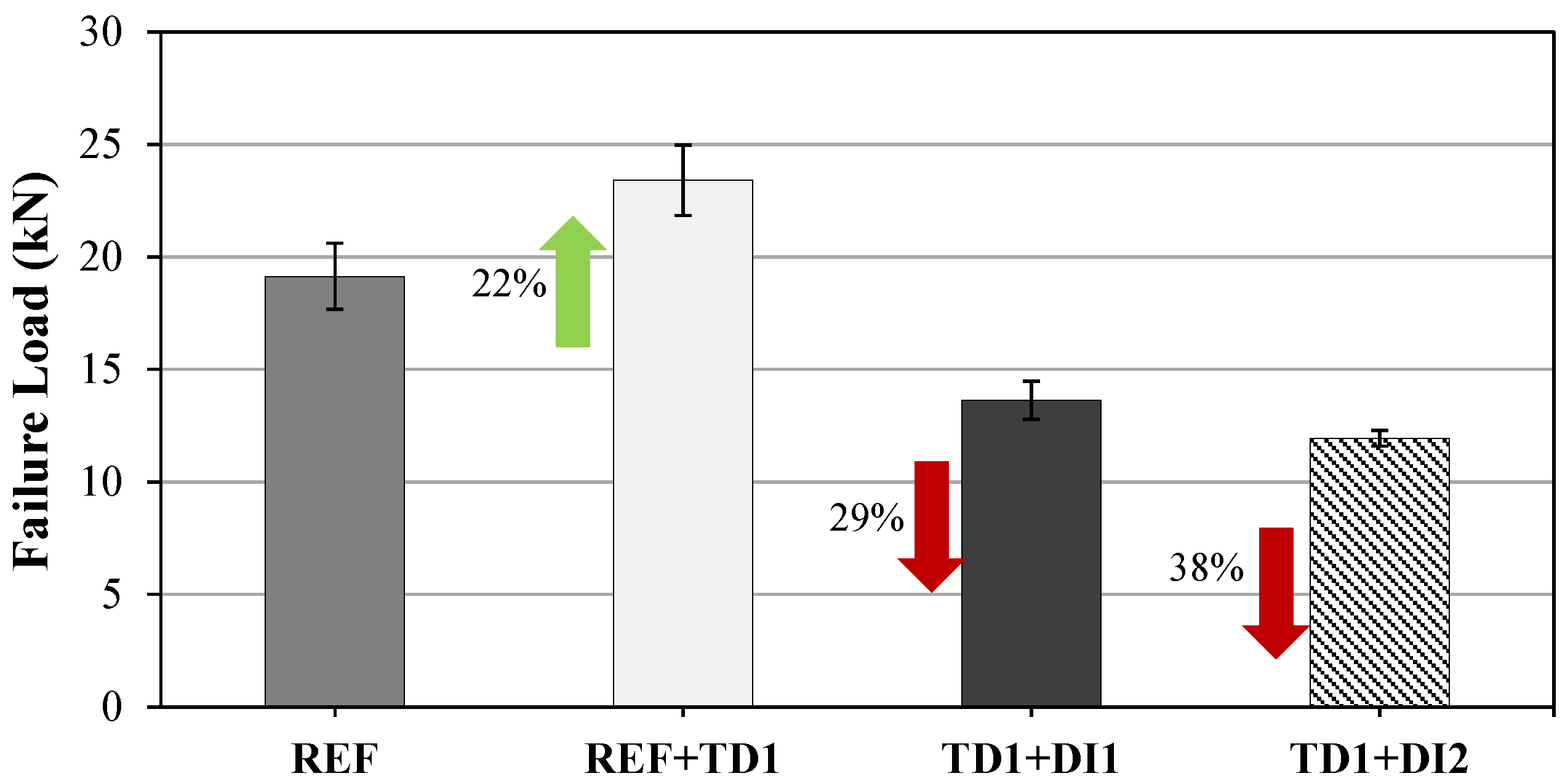
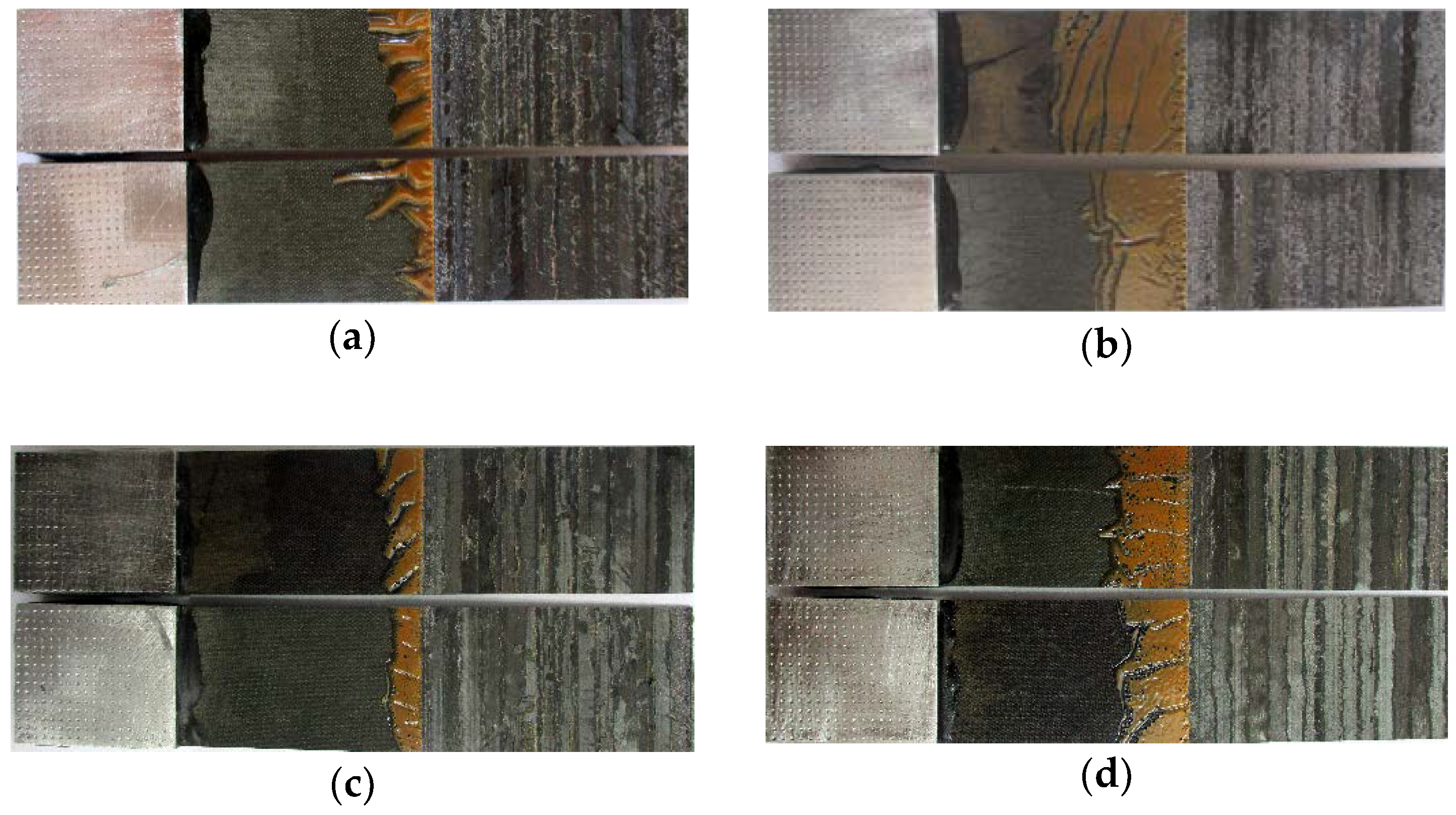
The geometry and dimensions of the samples is presented in Figure 4a. The scarfed samples were loaded under ambient conditions (25 °C/48% RH) by tensile stress using an MTS universal testing machine with a load capacity of 100 kN under a constant crosshead speed of 0.5 mm/min (Figure 4b) until a final separation of the two scarfed adherends occurred. Aluminum end tabs (30 × 25 × 2 mm) were bonded to the ends of the specimens using a two-part adhesive (PM Mega Cryl) in order to achieve a successful and smooth introduction of the load into the specimen. Moreover, the end tabs prevented gripping damage to the adherends or premature failure as a result of a significant discontinuity. The load and crosshead displacement were recorded using a computerized data logging system. A total of four tests were performed for each contamination scenario and the failure load was the mechanical feature used for comparing the tested specimens.

4. Results

During tensile testing, it was observed that prior to the final failure (i.e., the separation of the two adherends), all specimens presented an initial failure revealed by a first load drop in the region of the load displacement curves (Figure 5), which corresponds to plastic deformation. This failure was localized at the edges of the scarfed area and is attributed to stress concentrations at this point as well as to edge effects. Having overcome this marginal fracture, the initial failure propagated along the scarfed area and led to the final separation of the two adherends.
Despite this research investigating the effect of the combination of TD and DI contaminations on scarfed adhesive joints, the effect of the distinct TD1 is also presented here as it showed interesting results. Specifically, for the specimens prepared following one of the contamination scenarios, all samples of the REF+TD1 scenario presented a higher failure load, by 22%, than the reference samples (Figure 6). Although the exposure of flat CFRP adherends to an elevated temperature following the R-TD-1 scenario decreased the fracture toughness tested in mode-I and mode-II loading [12] such a decrease was not prominently observed in the tensile testing of the joints prepared from scarfed CFRP adherends. Even though heat usually damages the CFRP structure or causes chemical changes in the matrix, there have been reports that high temperatures can cause oxidation of the resin which may improve adhesion due to the formation of carbonyl groups at the surface [13,14].
When implementing scenarios comprising the successive application of two contamination cases, the obtained results revealed that the contamination combining thermal impact and deposits of dried de-icing fluid had a negative effect on the mechanical performance of the scarfed repair joints, reducing the tensile failure load as compared to specimens prepared following the reference scenario. Specifically, for samples from the TD1+DI1 scenario, the reduction of the failure load was 29%, while for the TD1+DI2 scenario the reduction reached 38% (Figure 6).
After the tensile tests, a detailed inspection of the fracture surfaces was conducted, using visual inspection according to the ASTM D5573 standard specifications [15] to aid a deeper understanding of the tensile test results. Figure 7 depicts the representative fracture surfaces of each contamination scenario studied, showing the main failure modes observed in the tensile specimens.
The percentages of the different failure modes are compared for the different sample sets in Figure 8. For the reference samples, a mixed-mode failure was observed, with the dominant failure being the fiber-tear failure, at 63% of the surface area, while adhesive failure was observed for 37% of the surface area. In contrast, the tested samples prepared following the REF+TD1 case presented a higher amount of cohesive failure (30%), while FT failure and the adhesive failure modes showed a reduction (43% and 27%) as compared to the reference samples. This change of the fracture pattern coincides with the increase in the failure load observed for the specimens prepared from scarfed adherends that had been exposed to elevated temperatures following the REF+TD1 scenario. This can be explained by the fact that cohesive failure requires a greater amount of energy for a crack to develop and propagate compared to adhesive failure or fiber-tear failure, thus presenting an increase in the failure load.
Inspecting the fracture patterns obtained for the TD1+DI1 samples, the fiber-tear remained the dominant failure. The observed increase of the area percentage (77%), as compared to samples prepared following the REF scenario, indicates that the combined successive contamination with TD1 and DI1 had a deleterious impact mainly on the behavior of CFRP adherends under tensile loading. Finally, after testing the TD1+DI2 set, the fiber-tear failure showed a slight reduction compared to the findings for TD1+DI1. Specifically, 71% of the surface area with a fiber-tear failure was observed, while adhesive failure increased to 29%. These findings indicate that the TD1+DI2 combined contamination affects mainly the bondline performance (the interphase between the adherends and adhesive).

5. Conclusions

Tensile tests were conducted on scarf joints containing thermal degradation and contamination with de-icing fluid to characterize the effects of pre-bond contamination on the lap-shear strength of scarf composite bonded joints. The results of the tensile mechanical testing revealed the effect of the thermal impact and de-icing fluid contamination scenario in the tensile performance of the scarfed samples. The single contamination of one of the adherends with TD1 proved to be beneficial since the sample presented a higher failure load than the reference samples. This was attributed to the enhancement of the matrix properties as a result of the oxidation and the formation of carbonyl groups at the surface as shown by the increased cohesive failure mode. However, the negative effect of the combination of the contaminations was demonstrated as the failure load of the scarf joints was significantly reduced by up to 38% and the bondline performance degraded as a result of the increased fiber-tear failure.
It is worth mentioning that the effects presented in this research refer to the specific loading geometry and bond preparation process, including cleaning process. The selection of suitable surface treatment, adhesive and bonding procedure is crucial for the bondline performance achieved in the end product.

Author Contributions

Conceptualization, K.T. and E.M.; methodology, K.T. and E.M.; investigation, K.T. and E.M.; resources, K.T.; data curation, E.M.; writing—original draft preparation, E.M.; writing—review and editing, K.T.; supervision, K.T.; funding acquisition, K.T. All authors have read and agreed to the published version of the manuscript.

Funding

This research was funded by European Union’s Horizon 2020 Programme, grant number no 636494 (Project COMBONDT: Quality Assurance Concepts for Adhesive Bonding of Aircraft Composite Structures by Extended NDT).

Institutional Review Board Statement

Not applicable.

Informed Consent Statement

Not applicable.

Conflicts of Interest

The authors declare no conflict of interest.

References

  1. Pantelakis, S.P.; Tserpes, K.I. (Eds.) Revolutionizing Aircraft Materials and Processes; Springer: Cham, Switzerland, 2020. [Google Scholar] [CrossRef]
  2. European Union Aviation Safety Agency (EASA). Bonded Repair Size Limits in Accordance with CS 2x.603 and AMC 20–29, Notification of A Proposal to Issue A Certification Memorandum; EASA Proposed CM–S–005 Issue: 01; European Union Aviation Safety Agency: Cologne, Germany, 2014.
  3. Pantelakis, S.P.; Tserpes, K.I. Adhesive bonding of composite aircraft structures: Challenges and recent developments. Sci. Chin. Phys. Mech. 2014, 57, 2–11. [Google Scholar] [CrossRef]
  4. Pantelakis, S.P.; Tserpes, K.I. (Eds.) Adhesive Bonding of Aircraft Structures. In Revolutionizing Aircraft Materials and Processes; Springer: Cham, Switzerland, 2020. [Google Scholar] [CrossRef]
  5. Da Silva, L.F.M.; Öchsner, A.; Adams, R.D. (Eds.) Introduction to adhesive bonding technology. In Handbook of Adhesion Technology; Springer: Berlin/Heidelberg, Germany, 2011; Volume 2, pp. 2–3. [Google Scholar]
  6. Cavalcanti, W.L.; Brune, K.; Noeske, M.; Tserpes, K.; Ostachowicz, W.; Schlag, M. (Eds.) Adhesive Bonding of Aircraft Composite Structures, Non Destructive Testing and Quality Assurance Concepts; Springer International Publishing: Berlin, Germany, 2021. [Google Scholar]
  7. Tserpes, K.I.; Markatos, D.N.; Brune, K.; Hoffmann, M.; Rau, E.; Pantelakis, S.P. A detailed experimental study of the effects of pre-bond contamination with a hydraulic fluid, thermal degradation, and poor curing on fracture toughness of composite-bonded joints. J. Adhes. Sci. Technol. 2014, 28, 1865–1880. [Google Scholar] [CrossRef]
  8. Ebnesajjad, S.; Landrock, A.H. Adhesives Technology Handbook; William Andrew Inc.: New York, NY, USA, 2008. [Google Scholar]
  9. Markatos, D.N.; Tserpes, K.I.; Rau, E.; Markus, S.; Ehrhart, B.; Pantelakis, S.P. The effects of manufacturing-induced and in-service related bonding quality reduction on the mode-I fracture toughness of composite bonded joints for aeronautical use. Compos. B Eng. 2013, 45, 556–564. [Google Scholar] [CrossRef]
  10. Moutsompegka, E.; Tserpes, K.I.; Polydoropoulou, P.; Tornow, C.; Schlag, M.; Brune, K.; Mayer, B.; Pantelakis, S. Experimental study of the effect of pre-bond contamination with deicing fluid and ageing on the fracture toughness of composite bonded joints. Fatigue Fract. Eng. Mater. Struct. 2017, 40, 1581–1591. [Google Scholar] [CrossRef] [Green Version]
  11. Shi, X. Airport Cooperative Research Program Synthesis 6, Impact of Airport Pavement Deicing Products on Aircraft and Airfield Infrastructure; Transportation Research Board: Washington, DC, USA, 2008. [Google Scholar]
  12. Tserpes, K.I.; Moutsompegka, E.; Schlag, M.; Brune, K.; Reguero Simon, A.; Ecault, R. Characterization of pre-bond contamination and ageing effects for CFRP bonded joints using reference laboratory methods, mechanical tests, and numerical simulation. In Adhesive Bonding of Aircraft Composite Structures: Non-Destructive Testing and Quality Assurance Concept; Cavalcanti, W.L., Brune, K., Noeske, M., Tserpes, K., Ostachowicz, W., Schlag, M., Eds.; Springer International Publishing: Berlin, Germany, 2021. [Google Scholar]
  13. Choi, D.M.; Park, C.K.; Cho, K.; Park, C.E. Adhesion improvement of epoxy resin/polyethylene joints by plasma treatment of polyethylene. Polymer 1997, 38, 6243–6249. [Google Scholar] [CrossRef]
  14. Ochoa-Putman, C.; Vaidya, U.K. Mechanisms of interfacial adhesion in metal–polymer composites—Effect of chemical treatment. Compos. Part A Appl. 2011, 42, 906–915. [Google Scholar] [CrossRef]
  15. ASTM International. ASTM D5573-99 Standard Practice for Classifying Failure Modes in Fiber-Reinforced-Plastic (FRP) Joints; ASTM International: West Conshohocken, PA, USA, 2008; Available online: www.astm.org (accessed on 30 November 2017).
Figure 1. (a) Photograph showing the automated tape laying process of the laminated panels; (b) diagram of the vacuum bag.
Jcs 05 00168 g001aJcs 05 00168 g001b
Figure 2. (a) Milling device; (b) overview of scarfed sample after milling.
Jcs 05 00168 g002
Figure 3. Autoclave thermal and pressure cycle for bonding repair samples with the adhesive FM®® 300-2.
Jcs 05 00168 g003
Figure 4. (a) Geometry and dimensions of the scarfed sample; (b) photograph showing a scarfed specimen under tensile loading.
Jcs 05 00168 g004
Figure 5. Load-displacement curves for reference and contaminated scarfed adhesive joints.
Jcs 05 00168 g005
Figure 6. Tensile failure load presented for each contamination scenario.
Jcs 05 00168 g006
Figure 7. Representative fracture surfaces of the scarf joints after loading in tension (a) REF; (b) REF+TD1; (c) TD1+DI; (d) TD1+DI2.
Jcs 05 00168 g007
Figure 8. Average percentages of the failure modes presented in the tensile tested scarfed joints, sorted according to the contamination scenario.
Jcs 05 00168 g008
Publisher’s Note: MDPI stays neutral with regard to jurisdictional claims in published maps and institutional affiliations.

